1
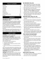
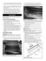
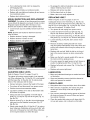
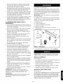
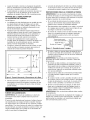
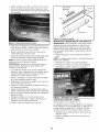
Operator's Manual
CRI:IFTSM I:1N°
i
PROFESSIONAL
i
13"
THICKNESS
PLANER
Model No.
351.217480
CAUTION:
Read and follow
all Safety Rules and Operating
Instructions before First Use
of this Product. Keep this
manual with tool.
Sears Brands Management
www.sears.com/craftsman
30783.00 Draft (10/07/09)
Corp., Hoffman
Estates, IL 60179 U.S.A.
BE PREPARED
Warranty
....................................
SafetyRules...............................
Unpacking..................................
Assembly.................................
Installation
.................................
Operation.................................
Maintenance
...............................
Troubleshooting
.............................
PartsIllustration
andList ...................
EspaSol
.................................
2
2-3
3
3-4
4-5
5-8
8-9
10
12-15
16-26
•
Wear proper apparel. Do not wear loose clothing,
gloves, neckties, rings, bracelets or other jewelry
which may get caught in moving parts of machine.
•
Wear protective hair covering to contain long hair.
•
Wear safety shoes with non-slip soles.
•
Wear safety glasses complying with United States
ANSI Z87.1. Everyday glasses have only impact
resistant lenses. They are NOT safety glasses.
•
Wear face mask or dust mask if operation is dusty.
•
Be alert and think clearly. Never operate power tools
when tired, intoxicated or when taking medications
that cause drowsiness.
PREPARE
ONE-YEAR FULL WARRANTY ON CRAFTSMAN
PROFESSIONAL TOOL
If this Craftsman tool fails due to a defect in material or
workmanship within one year from the date of purchase,
call 1-800-4-MY-HOME® TO ARRANGE FOR FREE
REPAIR (or replacement if repair proves impossible).
This warranty does not include expendable parts, such
as lamps, batteries, bits or blades.
If this tool is ever used for commercial or rental purposes,
this warranty will apply for only 90 days from the date of
purchase.
WORK
•
Keep work area clean. Cluttered work areas invite
accidents.
•
Do not use power tools in dangerous environments.
•
Do not use power tools in damp or wet locations. Do
not expose power tools to rain.
•
Work area should be properly lighted.
•
Proper electrical receptacle should be available for
tool. Three prong plug should be plugged directly
into properly grounded, three-prong receptacle.
•
Extension cords should have a grounding prong and
the three wires of the extension cord should be of
•
Keep visitors at a safe distance from work area.
•
Keep children out of workplace. Make workshop childproof. Use padlocks, master switches or remove switch
keys to prevent any unintentional use of power tools.
TOOL SHOULD
WARNING:
For your own safety, read all of the rules
and precautions before operating tool.
PROPOSITION
65 WARNING:
Some dust created
by power sanding, sawing, grinding, drilling and other
construction activities contains chemicals known to the
state of California to cause cancer, birth defects or
other reproductive harm.
.
Crystalline silica from bricks and cement and other
masonry products.
.
Arsenic and chromium from chemically-treated
ber.
lum-
Your risk from these exposures vary, depending on how
often you do this type of work. To reduce your exposure
to these chemicals: work in a well ventilated area and
work with approved safety equipment. Always wear
OSHA/NIOSH approved, properly fitting face mask or
respirator when using such tools.
Always unplug tool prior to inspection.
•
Consult manual for specific maintaining and adjusting procedures.
•
Keep tool lubricated and clean for safest operation.
•
Remove adjusting tools. Form habit of checking to
see that adjusting tools are removed before switching machine on.
•
Keep all parts in working order. Check to determine
that the guard or other parts will operate properly
and perform their intended function.
•
Check for damaged parts. Check for alignment of
moving parts, binding, breakage, mounting and any
other condition that may affect a tool's operation.
•
A guard or other part that is damaged should be
properly repaired or replaced. Do not perform
makeshift repairs. (Use parts list provided to order
replacement parts.)
KNOW HOW TO USE TOOL
CAUTION: Always follow proper operating procedures
as defined in this manual even if you are familiar with
use of this or similar tools. Remember that being careless for even a fraction of a second can result in severe
personal injury.
© Sears, Roebuck and Co,
BE MAINTAINED
°
Some examples of these chemicals are:
Lead from lead-based paints.
AREA FOR JOB
the correct gauge.
This warranty gives you specific legal rights and you may
also have other rights which vary from state to state.
Sears, Roebuck and Co., Hoffman Estates, IL 60179
.
FOR JOB
2
°
Use right tool for job. Do not force tool or attachment
to do a job for which it was not designed.
.
Disconnect tool when changing blades.
•
Avoid accidental start-up. Make sure that the switch
is in the OFF position before plugging in.
•
Do not force tool. It will work most efficiently at the
rate for which it was designed.
•
Keep hands away from moving parts and cutting
surfaces.
•
Never leave tool running unattended. Turn the power
off and do not leave tool until it comes to a complete
stop.
•
Do not overreach. Keep proper footing and balance.
•
Never stand on tool. Serious injury could occur if tool is
tipped or if blade is unintentionally contacted.
•
Know your tool. Learn the tool's operation, application and specific limitations.
•
Use recommended accessories (refer to page 13).
Use of improper accessories may cause risk of
injury to persons.
•
•
B
A
C
Figure 1 - Unpacking
WARNING:
Do not attempt assembly if parts are
missing. Use this manual to order replacement parts.
Handle workpiece correctly. Protect hands from possible injury.
INSTALL
Refer to Figure 12.
Turn machine off if it jams. Blade jams when it digs
too deeply into workpiece. (Motor force keeps it
stuck in the work.)
•
Always keep drive, cutterhead and blade guards in
place and in proper operating condition.
•
Feed work into blade or cutter against direction of
rotation.
•
Handle with knob (Key No. 27) should be installed to
top-right of the planer.
• Insert handle with knob onto elevation screw top
(Key Nos. 25 and 28).
CAUTION: Think safety! Safety is a combination of
operator common sense and alertness at all times
when tool is being used.
•
Secure handle with bolt using T-handle wrench (Key
No. 13) provided.
•
Insert plug into handle to cover bolt.
ATTACH DUST CHUTE
Refer to Figure 13.
WARNING:
Do not attempt to operate tool until it is
completely assembled according to the instructions.
Planer is best used along with a dust collector. Dust
chute is included. The dust chute (Key No. 34) is mounted to the rollercase (Key No. 31) using two thumb
screws (Key No. 63). The dust chute can be mounted to
direct chips to either side of planer.
Refer to Figure 1 below.
Check for shipping damage. If damage has occurred, a
claim must be filed with carrier. Check for completeness. Immediately report missing parts or damaged
parts. Call 1-800-266-9079 to obtain replacement parts.
•
After mounting, connect wet/dry vacuum hose to
dust chute. Be sure to turn the vacuum on before
operating the planer.
•
If you are using a 4" diameter hose dust collection
system, attach the exhaust adapter assembly (Key
No. 35) to the dust chute.
IMPORTANT: Remove protective paper from the table
before operating unit.
MOUNT
The planer comes assembled as one unit. Additional
parts which need to be fastened to planer should be
located and accounted for before assembling.
A Dust Chute
B
C
D
Thumb Screw (2)
Exhaust Adapter Assembly
Handle with Knob
E
Magnet Blade Removal (in toolbox)
F
4mm T-Handle Hex Wrnch (in toolbox)
HANDLE
PLANER TO WORK
SURFACE
Refer to Figure 2.
3
•
Planer is designed to be portable so it can be moved
to job site, but should be mounted to a stable, level
bench or table in a place with ample lighting and
correct power supply.
•
Make sure there is plenty of room for moving the
workpiece through the entire cut. There must be
enough room that neither the operators or the
bystanders will have to stand in line with the wood
while using the tool.
•
Base of planer has four mounting holes.Mount planer to workbench or tool stand using bolts, flat washers and hex nuts (not supplied).
.
Figure 2 shows the base dimensions, mounting
holes and required space to allow for table assembly
in horizontal position.
°
Do not remove or alter grounding prong in any manner.
In the event of a malfunction or breakdown, grounding
provides a path of least resistance for electrical shock.
WARNING:
Do not permit fingers to touch the terminals of plug when installing or removing from outlet.
.
Plug must be plugged into matching outlet that is
properly installed and grounded in accordance with
all local codes and ordinances. Do not modify plug
provided. If it will not fit in outlet, have proper outlet
installed by a qualified electrician.
. Inspect tool cords periodically, and if damaged, have
repaired by an authorized service facility.
o Green (or green and yellow) conductor in cord is the
grounding wire. If repair or replacement of the electric cord or plug is necessary, do not connect the
green (or green and yellow) wire to a live terminal.
3/8" Dia. J
231/2"
--4
.
26"
Figure 2 - Base Dimensions and Required Space
Securely mount planer to work table by bolting it
through the holes. Make sure the planer does not
rock and the work table is level.
POWER
WARNING: Any receptacle replacement should be
performed by a qualified electrician.
A temporary 3-prong to 2-prong grounding adapter (see
Figure 4 is available for connecting plugs to a two pole
outlet if it is properly grounded.
SOURCE
Grounding Lug _
Adapter
WARNING: Do not connect planer to the power
source until all assembly steps have been completed.
3-Prong
The motor is designed for operation on the voltage and
frequency specified. Normal loads will be handled safely
on voltages not more than 10% above or below specified voltage. Running the unit on voltages which are not
within range may cause overheating and motor burnout. Heavy loads require that voltage at motor terminals
be no less than the voltage specified.
.
*
.
.
INSTRUCTIONS
°
Check with a qualified electrician if you do not
understand grounding instructions or if you are in
doubt as to whether the tool is properly grounded.
This tool is equipped with an approved cord and a
3-prong grounding type plug (see Figure 3) for your
protection against shock hazards.
_=L_
Many cover plate screws, water pipes and outlet
boxes are not properly grounded. To ensure proper
ground, grounding means must be tested by a qualified electrician.
EXTENSION
.
Grounding plug should be plugged directly into
a properly installed and grounded 3-prong
grounding-type receptacle, as shown (see Figure 3).
Grounding Prong,_
Do not use a 3-prong to 2-prong grounding adapter
unless permitted by local and national codes and
ordinances. (A 3-prong to 2-prong grounding adapter
is not permitted in Canada.)
Where a 3-prong to 2-prong grounding adapter is
permitted, the rigid green tab or terminal on the side
of the adapter must be securely connected to a
permanent electrical ground such as a properly
grounded water pipe, a properly grounded outlet box
or a properly grounded wire system.
WARNING: Improper connection of equipment
grounding conductor can result in the risk of electrical
shock. Equipment should be grounded while in use to
protect operator from electrical shock.
.
Make Sure This
Is Connected
To A Known
Ground
2-Prong Receptacle
Figure 4 - 2-Prong Receptacle with Adapter
Power supply to the motor is controlled by a switch
with key. Removing the key from switch will lock the
unit and prevent unauthorized use.
GROUNDING
A 2-prong wall receptacle must be replaced with a
properly grounded 3-prong receptacle installed in
accordance with National Electric Code and local
codes and ordinances.
.
CORDS
The use of any extension cord will cause some drop
in voltage and loss of power.
Wires of the extension cord must be of sufficient size
to carry the current and maintain adequate voltage.
o Use the table to determine the minimum wire size
(A.W.G.) extension cord.
.
!1
3-Prong Plug ,-__
._J[
J
Properly Grounded Outlet\ _,_
Figure 3 - 3-Prong Receptacle
4
Use only 3-wire extension cords having 3-prong
grounding type plugs and 3-pole receptacles which
accept the tool plug.
.
Base Size ..........................
If the extension cord is worn, cut or damaged in any
way, replace it immediately.
Extension Cord Length
Wire Size ..............................
Workpiece Width (max.) ......................
Workpiece Thickness (max.) ...................
Maximum Depth of Cut .......................
Cuts Per Minute .........................
Feed Rate .............................
A.W.G.
Up to 25 ft ..................................
25 to 50 ft ..................................
14
12
Overall Dimensions
NOTE: Using extension cords over 50 ft. long is not
recommended.
OPERATION
The 120 Volt AC universal motor has the following
specifications:
Single
Cutterhead RPM .........................
10,000
WARNING:
CAUTION:
cautions:
CONNECTIONS
Make sure unit is turned off and discon-
nected from power source before inspecting any wiring.
The motor is assembled with an approved three conductor cord to be used on 120 volts as indicated. The
power supply to the motor is controlled by a double
pole locking switch.
The power lines are connected directly to the switch.
The green ground line must remain securely fastened
to the frame to properly protect against electrical shock.
A manual reset overload protector is installed in line
with the power supply to the motor. If the planer is overloaded, the protector will break the circuit.
DESCRIPTION
Craftsman 13" planer finishes rough-cut lumber to size
and planes soft and hardwoods up to 6" thick and 13"
wide. Wood feeds into three-blade cutterhead by rubber
infeed/outfeed rollers. Sturdy base construction, granite
table and four-post design permits smooth feeding and
virtually snipeless planing. Planer comes with enclosed,
universal ball bearing, 15 Amp motor with overload protection. Motor has ON/OFF switch with removable key to
prevent accidental start-up. Unit features depth-of-cut
gauge for convenient set-up, workpiece thickness
pre-set gauge with 8 settings for consistent set-up, easy
hands-free replacement of blades for safety and minimized downtime, top mounted rollers for workpiece
return and built-in carrying handles for portability. Planer
takes cuts up to 3/j, per pass at 26 feet per minute. Inch
height scale has graduations in 1/16"increments, and
metric height scale has graduations in lmm increments.
25W' W x 34W' D x 24¼" H
94 Ibs
101 Ibs
RULES
13" x 93/4"
14" x 12"
5
Always observe the following safety pre-
•
Know general power tool safety. Make sure all precautions are understood (see pages 2, 3, 5 and 6).
•
Whenever adjusting or replacing any parts on planer,
turn switch OFF and remove plug from power source.
•
Make sure all guards are properly attached and
securely fastened.
•
Make sure all moving parts are free from interference.
•
Always wear eye protection or face shield.
•
Make sure blades are aligned and properly attached
to cutterhead.
•
Do not plug in planer unless switch is in off position.
After turning switch on, allow planer to come to full
speed before operating.
•
Keep hands clear of all moving parts.
•
Do not force cut. Slowing or stalling will overheat
motor. Allow automatic feed to function properly.
•
Use quality lumber. Blades last longer and cuts are
smoother with good quality wood.
•
Do not plane material shorter than 15", narrower
than 8/4"_wider than 13" or thinner than 1/2".
•
Never make planing cut deeper than %_".
•
For workpieces longer than 24"_ use material
support stands. See Recommended Accessories,
page 13.
Do not back the work toward the infeed side.
•
SPECIFICATIONS
Table Size ............................
Extension Table Size ....................
1/8"
30,000
26 FPM
WARNING:
Operation of any power tool can result in
foreign objects being thrown into eyes which can result
in severe eye damage. Always wear safety goggles
complying with United States ANSI Z87.1 (shown on
package) before commencing power tool operation.
15
60
Phase ..................................
SAFETY
13"
6"
WARNING: For your own safety, read all of the
instructions and precautions before operating tool.
120
Amperes ...................................
Hertz .....................................
ELECTRICAL
......
Weight .................................
Shipping Weight .........................
MOTOR
Voltage ...................................
23_ x 13W'
•
Take precautions against kickback. Do not permit anyone to stand or cross in line of cutterhead's rotation.
Kickback or thrown debris will travel in this direction.
•
Turn switch off and disconnect power whenever
planer is not in use.
•
Replace knives as they become damaged or dull.
•
Keep planer maintained. Follow maintenance
instructions (see pages 8 -9).
OPERATING
CONTROLS
CAUTION: Be sure to turn the planer off prior to resetting the circuit breaker to avoid unintentional start-up of
the planer.
ON/OFF SWITCH
Refer to Figure 5.
DEPTH
The ON/OFF switch is located on the front of the planer
motor. To turn the planer ON, move the switch to the up
position. To turn the planer OFF, move the switch to the
down position.
OF CUT
Refer to Figure 12.
Thickness planing refers to the sizing of lumber to a
desired thickness while creating a level surface parallel
to the opposite side of the board. Board thickness which
the planer will produce is indicated by the scale (Key
No. 30).
Depth-of-cut is adjusted by raising or lowering the
rollercase using handle (Key No. 27).
. Each full rotation of the handle moves the rollercase
1/16
.
Quality of thickness planing depends on the operator's judgement about the depth of cut.
.
Depth of cut depends on the width, hardness, dampness, grain direction and grain structure of the wood.
Maximum thickness of wood which can be removed
.
Figure 5 - ON/OFF Switch and Circuit Reset
SWITCH LOCK
Refer to Figure 6.
The planer can be locked from unauthorized use by
locking the switch. To lock the switch:
•
•
.
Turn the switch to OFF position and disconnect planer from power source.
in one pass is '/8" for planing operations on workpieces up to 6" wide. Workpiece must be positioned
away from the center tab on the rollercase to cut W'.
Maximum thickness of wood which can be removed
in one pass is '/,6" for planing operations on workpiece from 6" up to 13" wide.
CAUTION: A %2"depth-of-cut on hard, softwood 6-13"
wide can be made. However, continuous operation at
this set-up can cause premature motor failure.
Pull the key out. The switch cannot be turned on with
the key removed.
NOTE: Should the key be removed from the switch at
the ON position, the switch can be turned off but cannot
be turned on.
•
tt
.
For optimum planing performance, the depth of cut
should be less than 1/18".
.
Board should be planed with shallow cuts until the
work has a level side. Once a level surface has been
created, flip the lumber and create parallel sides.
.
Plane alternate sides until the desired thickness is
obtained. When half of total depth of cut is taken from
each side, the board will have a uniform moisture content and additional drying will not cause it to warp.
.
Depth of cut should be shallower when work is wider.
.
When planing hardwood, take light cuts or plane the
wood in thin widths.
.
Make a test cut with a test piece and verify the thickness produced.
.
Check accuracy of test cut prior to working on finished product.
To replace key, slide key into the slot on switch until
it snaps.
DEPTH-OF-CUT
ure 6
Switch
GAUGE
Refer to Figure 13.
Lock
A spring loaded depth-of-cut gauge (Key No. 23) is
attached to front of rollercase. The pointer on depth-ofcut gauge accurately displays the depth-of-cut per pass
when workpiece is positioned below the gauge.
Cranking the handle moves the rollercase down and the
pointer shows depth-of-cut up to 3/82"
CIRCUIT BREAKER
Refer to Figure 5.
The planer is equipped with a motor protection
device-circuit breaker. The breaker will automatically
shut the planer off when excessive current is consumed.
If the breaker is tripped, turn the planer off and reset
the circuit by pressing the button.
6
Recommended
Maximum Depth-Of-Cut:
Hard/Softwood up to 6" wide: ..................
Hard/Softwood 6-1 3" wide: ......................
1/8"
%2"
•
Twisted or severely warped boards can jam planer.
Rip lumber in half to reduce magnitude of warp.
•
Work should be fed into planer in same direction as
the grain of the wood. Sometimes grain will change
directions in middle of board. In such cases, if possible, cut board in middle before planing so grain
direction is correct.
CAUTION: A 8/82"depth-of -cut on hard, softwood
6-1 3" wide can be made. However, continuous operation at this set-up can cause premature motor failure.
WORKPIECE THICKNESS
PRE-SET GAUGE
CAUTION: Do not plane board which is less than 15"
long; force of cut could split board and cause kickback.
Refer to Figure 7.
An eight position workpiece thickness pre-set control
knob is mounted on right side of planer. This knob allows
operator to preset the desired finished workpiece thickness. Eight settings are provided: W', W', 1/2",8/4",1 ", 1W',
1 W'and 18/4".
FEEDING
WORK
The planer is supplied with planing blades mounted in the
cutterhead and infeed and outfeed rollers adjusted to the
correct height. Planer feed is automatic; it will vary slightly
depending on type of wood.
• Feed rate refers to rate at which lumber travels
through planer.
Example: Plane a 2" thick workpiece up to 11/4".
•
Raise or lower rollercase until it is just above the
workpiece.
•
Position the workpiece on the planer table below the
rollercase.
•
Align work perpendicular to rollercase so that work
feeds through planer straight.
•
Rotate knob until 11/4"is indicated.
•
•
The planer is now set to stop the rollercase when
the workpiece thickness reaches 11/4".
Raise/lower rollercase to produce the depth of cut
desired.
•
Stand on side to which the handle is attached.
•
Boards longer than 24" should have additional support from free standing material stands.
•
Position the workpiece with the face to be planed on
top.
•
Turn the planer on.
•
Rest board end on table and direct board into planer.
•
Gently slide workpiece into the infeed side of the
planer until the infeed roller begins to advance the
workpiece.
•
Let go of the workpiece and allow automatic feed to
advance the workpiece.
•
Do not push/pull on workpiece. Move to the rear and
receive planed lumber by grasping it in same manner as it was fed.
NOTE: To reset for a different depth stop, raise the
rollercase by about 2 rotations. Turn knob to desired
set-up.
CAUTION: To avoid risk of injury due to kickbacks, do
not stand directly in line with front or rear of planer.
Figure 7 - Workpiece
Thickness
•
Do not grasp any portion of board which has not
gone past out-feed roller.
•
Repeat this operation on all boards which need to be
same thickness.
Planer has return rollers on top so assistant can
pass work back to operator.
Pre-set Guage
AVOID DAMAGE TO BLADES
•
Thickness planer is a precision woodworking
machine and should be used on quality lumber only.
•
•
Do not plane dirty boards; dirt and small stones are
abrasive and will wear out blade.
NOTE: Assistant must follow same precautions as
operator.
•
Remove nails and staples. Use planer to cut wood only.
•
•
Avoid knots. Heavily cross-grained wood makes
knots hard. Knots can come loose and jam blade.
Avoiding
CAUTION: Any article that encounters planer blades
may be forcibly ejected from planer creating risk of injury.
PREPARE
Thickness planer works best when lumber has at
least one flat surface.
•
Use surface planer or jointer to create a flat surface.
7
Snipe
•
Snipe refers to a depression at either end of board
caused by an uneven force on cutterhead when work
is entering or leaving planer.
•
Snipe will occur when boards are not supported
properly or when only one feed roller is in contact
with work at beginning or end of cut.
WORK
•
Surface that the planer will produce will be smoother
if shallower depth of cut is used.
•
To avoid snipe, gently push the board up while feeding the work until the outfeed roller starts advancing
it
•
Move to the rear and receive planed board by gently
pushing it up when the infeed roller looses contact
with the board
•
When planing more than one board of the same
thickness, butt boards together to avoid snipe
•
Snipe is more apparent when deeper cuts are taken
•
Feed work in direction of grain Work fed against
grain will have chipped, splintered edges
•
Loosen and remove three screws and belt guard
•
Press cutterhead latch down and carefully rotate belt
towards you until cutterhead locks in position
Planer will operate best if kept in good condition and
properly adjusted
CHECK
FOR WORN
BLADES
Figure 9 - Remove Gib Bolts
•
Condition of blades will affect precision of cut
Observe quality of cut which planer produces to
check condition of blades
•
•
Dull blades will tear, rather than sever wood fibers
and produce fuzzy appearance
Loosen, but do not remove, eight screws located on
gib Loosen screws just enough so that gib is loose,
allowing blade to be removed
•
•
Raised grain will occur when dull blades pound on
wood that has varying density Raised edge will also
be produced where blades have been nicked
Insert the magnetic blade removal tool under the
center of the gib
•
Lift the tool up until blade is free of pins and then
remove blade
•
Blades on this planer are reversible Blades should
always be reversed or replaced as matched set
Keeping a spare set of blades on hand is recommended
NOTE: Magnet can be easily disengaged from gib by
tilting it to left or right
CAUTION: Blade edges are extremely sharp Keep fingers away from blades at all times
•
WARNING:
Always turn planer OFF and disconnect
from power source before starting any maintenance
work
Blade is located in position by two pins Carefullly lift
old blades from cutterhead using magnets Do not
make contact with the blade using fingers Use
magnet only
•
Reverse or replace blade and carefully position it on
the two pins using magnet
•
•
Replace gib and align the holes on the gib with
holes on the blade using magnet
•
Secure gib to cutterhead using eight bolts earlier
•
Depress latch to release cutterhead Release latch
when cutterhead can be turned by hand
CHANGING
BLADES
Refer to Figures 8-10 page 8
Loosen and remove thumb screws from dust chute
and hood on the rear side of planer Remove chute
and hood
Spring
Magnet Tool
Blade
-'x
Gib
Pin
Cutterhead
Figure 8 - Remove Dust Chute and Hood
Figure 10 - Remove Blade
8
.
Turn cutterhead by hand until it is stopped by
self-engaging latch.
.
Re-engage the right and elevation screw gear and
replace retaining ring to secure.
.
Remove gib and blade as mentioned earlier.
°
Release and remove vise plier.
.
Replace with new blade and replace gib and secure
it as mentioned earlier.
o Set the planer back on its base.
.
Replace dust chute and hood.
BRUSH
INSPECTION
o Make a test cut to verify adjustment.
REPLACING
AND REPLACEMENT
Refer to Figures 12 and 13, pages 12 and 14.
WARNING: Turn planer off and disconnect from power
source. Brush life depends on amount of load on motor.
Regularly inspect brushes after 100 hours of use.
Brushes are located on either side of planer motor.
°
Inadequate tension in the V-belt (Fig. 13, Key No. 53)
will cause the belt to slip from the motor pulley (Fig. 13,
Key No. 55) or drive pulley (Fig. 13, Key No. 52). Loose
belt must be replaced. To replace V-belt:
Loosen brush cap and carefully remove brush from
motor.
NOTE: Brushes are located on both front and rear
sides of planer.
°
Replace brushes if spring is damaged.
°
Replace brushes if carbon is worn.
.
Replace brushes and tighten brush caps.
TABLE LEVEL
The planer will produce uneven depth of cut (tapered
cut) if the rollercase (Fig. 13, Key No. 31 ) is not parallel
with the base (Fig. 12, Key No. 34). To restore parallelism of the rollercase with the base:
Turn planer off and disconnect from power source.
Fold the front and rear extension tables.
.
Lay planer carefully on it's side so that bottom side
of the base is exposed.
°
Clamp vise plier (not supplied) on the left side of
shaft (Fig. 12, Key No. 52) next to the gear (Fig. 12,
Key No. 56).
°
Remove screw (Fig. 12, Key No. 59) and disengage
right gear from the elevation screw gear (Fig. 12,
Key No. 56).
°
Slowly rotate handle (Fig. 12, Key No. 27) to raise or
lower rollercase. Rollercase will move by 0.006" with
every turn of the gear by one tooth. Move rollercase
tot he required distance to offset the taper.
°
Loosen and remove screws on right cap (Fig. 12,
Key No. 28). Remove panel (Fig. 12, Key No. 29).
.
Loosen and remove screws (Fig. 13, Key No. 28) on
belt guard (Fig. 13, Key No. 27). Remove belt guard.
.
Remove old belt by walking the belt from motor
and drive pulleys alternatively. Push motor down and
pull the belt outward while turning the pulleys at the
same time.
.
Replace with new belt. Walk the belt on to the pulleys in the reverse manner as when removing the
belt.
.
Make sure the belt is evenly seated all the way on
the motor and drive pulley grooves.
.
Pry motor upward to apply tension to belt. Secure in
position by tightening bolt (Fig. 13, Key No. 39).
.
Replace belt guard and screws (Fig. 13, Key Nos. 27
and 28).
.
Replace and secure right panel.
.
Motor and cutterhead bearings are sealed and need
no lubrication.
.
Gears and elevation screws should be cleaned of
debris and greased as needed.
CLEAN
Using a test piece, measure the height of the taper.
.
.
Turn planer off and unplug from power source.
LUBRICATION
Refer to Figures 12 and 13, pages 12 and 14.
.
°
o Loosen bolt (Fig.13, Key No. 39) to loosen motor
assembly.
Figure 11 - Replace Brushes
ADJUSTING
V-BELT
9
PLANER
•
Keep planer clean of any wood chips, dust, dirt or debris.
•
After 10 hours of operation, the chains and gears
should have wood chips, dust and old grease
removed.
•
Use common automotive bearing grease to lubricate
all chains and gears. Be sure all chains and gears
have plenty of grease.
•
Clean the granite table using a soft, damp cloth. Do
not use any waxes, oils or solvents on the table.
SYMPTOM
POSSIBLE
Snipe
(gouging at ends of board)
1.Dull blades
1.Reverse or replace blades per instructions.
See "Maintenance"
2. Inadequate support of long boards
3.Uneven force on cutterhead
2.Support long boards. See "Avoiding Snipe"
3.Gently push board when board is in contact
with only one feed roller. See "Avoiding Snipe"
4.Adjust rollercase
See "Adjusting Table Level"
5.Butt end to end each piece of stock as
boards pass through planer
4.Rollercase
CAUSE(S)
not level with base
5.Lumber not butted properly
CORRECTIVE
ACTION
Fuzzy grain
Planing wood with a high moisture
content
Remove high moisture content from wood by
drying.
Torn grain
1.Too heavy a cut
2. Blades cutting against grain
3.Dull blades
1.Review "Depth of Cut"
2. Review "Feeding Work"
3. Replace blades per instructions
See "Maintenance"
Rough raised grain
1.Dull blades
1.Replace blades per instructions
See "Maintenance"
2.Too heavy a cut
3.Moisture content too high
2.Review "Depth of Cut"
3.Dry the wood or use dried wood
Uneven depth of cut
(side to side)
Rollercase not level with planer
base
Rollercase not level
See "Adjusting Table Level"
Rollercase elevation adjusts
with difficulty
1.Gears dirty
1.Clean and lubricate gears
2.Clean and lubricate elevation screws
2. Elevation screws dirty
3.Gears, elevation screws worn
4.Friction between rollercase and
covers
5.Rollercase
base
Board feeds inside, but stops
moving past the outfeed roller
1.0utfeed
not parallel with planer
roller cannot rotate due
3. Replace gears, elevation screws
4.Clean and lubricate
5.Adjust rollercase.
See "Adjusting Table Level"
to clogging of chips
2.Too much pressure on the
cutterhead from long workpiece
1.Clear the clogging from dust collection
system. See "Clean Planer"
2.Use support stands to support workpiece
longer than 24"
Board thickness does not
match depth of cut scale
Indicator not set correctly
Adjust indicator and tighten securely
Chain jumping
1.Sprockets worn
2.Chain worn
1.Replace sprockets
2.Replace chain
Planer will not operate
1.No power to planer
1.Check power source by qualified electrician.
2. Motor overload protection tripped
2.Turn planer off. Reset motor overload
protection. See "Overload Reset"
3.Check switch and wiring by qualified
electrician
3.Defective or loose switch or wiring
Belt slipping
Loose belt
Replace belt, see "Replacing V-Belt"
10
NOTES
11
Model 351.217480
Figure 12 -
Replacement
Parts Illustration
for Base
11
6
/
12
|
_/24
16
/
18
20
_.j21
44
43
45
46.
22
47_
12
22
KEY
NO.
PART NO.
DESCRIPTION
KEY
NO.
PART NO.
DESCRIPTION
1
30852.00
Short Tube
2
30853.00
2
33
STD863510
5-0.8 x 10mm Pan Head Screw*
4
Upper Bearing Seat
4
34
N/A
Base
1
3
30854.00
4
30855.00
Bushing
Washer
3
35
24641.00
8mm Steel Ball
1
4
36
30878.00
Spring
5
1
30856.00
Roller Assembly
2
37
30879.00
Depth Stop Base
1
6
30857.00
2
38
30880.00
7
07541.00
Long Tube
4-0.7 x 8mm Socket
16
39
30859.00
Depth Stop Step
Shoulder Bolt
1
1
4O
30881.00
Plate
3
QTY.
Pan Head Screw
8
STD315501
9
30877.00
6000zz Ball Bearing*
5-0.8 x 16mm Socket
QTY.
1
41
05110.00
6-1.0 x 20mm Set screw
3
4
42
30862.00
Nut
3
43
STD840610
6-1.0mm Hex Nut*
4
Pan Head Screw
lO
01781.00
5mm Flat Washer (N)
4
44
STD833025
6-1.0 x 25mm Hex Head Bolt*
4
11
30858.00
1
45
30882.00
12
30860.00
Left Top Cap
Blade Removal Tool
1
46
STD863510
Spring Plate
5-0.8 x 10mm Pan Head Screw*
4
8
13
30861.00
4mm Hex T-wrench
1
47
30883.00
Chain
1
14
30863.00
Left Side Panel Assembly
1
48
30884.00
Idler Gear
2
15
30864.00
2
49
30885.00
Idler Gear Shaft
2
16
30865.00
Elevation Screw Assembly
Left Rail Guide
1
50
05713.00
5-0.8 x 25mm Socket
2
17
30866.00
Granite Table
1
18
STD870510
5-0.8 x 10mm Socket Head Bolt*
4
51
30886.00
19
30748.00
6-1.0 x 35mm Socket
3
52
30887.00
Spacer
Shaft
2
2
53
STD870512
5-0.8 x 12mm Socket Head Bolt*
8
2o
STD852006
6mm Lock Washer*
3
54
30888.00
Support
4
21
30867.00
1
55
30889.00
22
30868.00
Right Rail Guide
Extension Table
2
56
30890.00
Spacer
Bevel Gear
6
8
23
01210.00
5-0.8 x 5mm Set Screw
1
57
30891.00
Bushing
8
24
30869.00
Spacer
1
58
30892.00
25
30870.00
Elevation Screw Assembly (RF)
1
59
07537.00
Spacer
4-0.7 x 10mm Socket Head Bolt
8
8
26
30871.00
Elevation Screw Assembly (RR)
1
6O
30893.00
Spacer
4
27
30872.00
Crank Handle Assembly
1
61
STD315501
6000zz Ball Bearing*
4
28
30873.00
Right Top Cap
1
62
30894.00
29
30874.00
63
06471.00
4
8
30
24764.00
Right Side Panel
Scale
1
Bearing Retainer
5-0.8 x 12mm Socket
31
30876.00
Screw
32
64
30895.00
Sprocket
2
32
N/A
Support
4
65
30896.00
Spacer
2
Pan Head Screw
Pan Head Screw
1
Pan Head Screw
*
Standard hardware item available locally
N/A Not available as replacement part
A
Not Shown
Recommended
13
Accessories
A
Horizontal Roller Stand
9-21417
A
Three-Roller
9-22268
Stand
Model 351.217480
Figure 13 -
Replacement
Parts Illustration
for Rollercase
4
63
32
€
29
30
13
49
9
8
9
56
_57
50
i 2 53
/
60
i¢
61
55
58
54
14
KEY
NO.
PART NO.
DESCRIPTION
KEY
NO.
PART NO.
DESCRIPTION
1
30798.00
2
30799.00
Motor Assembly (Inc. Key Nos. 2-6)
Brush Holder
1
2
34
30818.00
Dust Chute
1
3
30800.00
Brush (Set of 2)
35
30819.00
36
30822.00
Exhaust Adapter Assembly
Cutterhead Lock
1
1
4
30801.00
Brush Cap
2
37
30823.00
1
Switch w/Key
Circuit Breaker
1
1
38
STD870516
Spacer
5-0.8 x 16mm Socket Head Bolt*
5
30802.00
6
30803.00
39
02229.00
8-1.25 x 20mm Socket
7
00533.00
1
8
30804.00
3AM1-15 Retaining Ring
Chain
3
2
4O
STD851008
8mm Flat Washer*
1
9
30805.00
Sprocket
4
41
30824.00
Depth Stop Assembly
1
10
30806.00
Spacer
5-0.8 x 35mm Socket Head Bolt*
1
4
42
30825.00
6
43
30826.00
Spring
Gib
1
1
44
09789.00
6-1.0 x 16mm Socket
QTY.
QTY.
1
1
Pan Head Screw
11
STD870535
12
30807.00
13
30808.00
Gearbox Assembly
Cover
14
30809.00
Pinion
1
45
30827.00
Pin
6
15
01516.00
5-0.8 x 8mm Set Screw
1
46
30828.00
Blade (set of 3)
1
16
01474.00
5mm Serrated Washer
2
47
07322.00
1
17
STD852005
5mm Lock Washer*
3
48
30830.00
5 x 5 x 12mm Key
Cutterhead
18
STD863508
5-0.8 x 8mm Pan Head Screw*
2
49
STD315235
6203ZZ Ball Bearing*
2
19
30810.00
1
1
50
30831.00
Bearing Retainer
5-0.8 x 10mm Socket Head Bolt*
1
1
3
24
Pan Head Screw
1
2O
16133.00
Cord Clamp
5-0.8 x 10mm Washer Head Screw
51
STD870510
21
30811.00
Screw
3
52
30832.00
22
30812.00
Chip Deflector
1
53
30833.00
Cutterhead Pulley
Drive Belt
23
30813.00
24799.00
16mm Hex Nut (LH)
1
STD863216
1
2
54
24
Depth of Cut Gauge Assembly
3-0.5 x 16mm Pan Head Screw*
55
30834.00
Motor Pulley
1
25
30814.00
1
8
30835.00
LH Spring
2
04869.00
Depth Indicator
5-0.8 x 6mm Set Screw
56
26
57
30836.00
4
27
30815.00
Belt Guard
1
58
30837.00
Bearing Block
Infeed Roller
28
30712.00
4-0.7 x 10mm Washer Head Screw
3
59
30838.00
Outfeed Roller
1
29
30820.00
Plunger
1
6O
30839.00
RH Spring
2
30
30821.00
1
1
61
30840.00
4
62
30841.00
Retaining Plate
Screw
2
63
30842.00
Thumbscrew
2
1
A
30783.00
Operator's Manual
1
31
N/A
Spring
Rollercase
32
30816.00
Knob
33
30817.00
Dust Hood Assembly
*
Standard hardware item available locally
N/A Not available as replacement part
2,
Not Shown
15
3
1
1
8
•
Aprenda las normas de seguridad generales para el uso
de herramientas mecanicas. Aseg_rese de comprender
todas las precauciones (vea las paginas 20, 21,24 y 25).
•
Cuando ajuste o reemplace cualquier pieza de la cepilladora, Ileve el interruptor a la posici6n OFF (apagado)
y retire el enchufe de la fuente de alimentaci6n.
•
Aseg_rese que todos los protectores est_n correctamente
acoplados y firmemente sujetos.
•
Aseg_rese que nada obstaculice ninguna pieza m6vil.
•
Siempre use protecci6n
•
Aseg_rese que las cuchillas est_n alineadas y correctamente acopladas al portacuchilla.
•
No enchufe la cepilladora a menos que el interruptor est_
en la posici6n de OFF (apagado). Despu_s de encender
el interruptor, permita que la cepilladora alcance toda la
velocidad antes de usar.
Cortacircuito
para los ojos o para la cara.
Figura 5 - Interruptor de ON/OFF (Encendido/Apagado)
y reajuste del circuito
TRABA DEL INTERRUPTOR
Vea la Figura 6.
•
•
Mantenga las manos alejadas de las piezas m6viles.
No fuerce el corte. Si disminuye la velocidad o se
queda atascado, se recalienta el motor. Permita que
la alimentaci6n automatica funcione correctamente.
Se puede impedir el uso no autorizado de la cepilladora
trabando el interruptor. Para trabar el interruptor:
•
•
Use madera de calidad. Las cuchillas duran mas y los
cortes resultan mas uniformes si la madera es de buena
calidad.
Gire el interruptor a la posici6n OFF (apagado) y
desconecte la cepilladora de la fuente de alimentaci6n.
•
Extraiga la Ilave. No se puede Ilevar el interruptor a la
posici6n de encendido sin la Ilave.
•
•
No cepille material que tenga menos de 15" de Iongitud,
menos de 3/4"de ancho, mas de 13" de ancho o menos
de 1/2"de espesor.
Nunca haga un corte de cepillado mayor de 3/32"de
profundidad.
•
Para piezas de trabajo con una Iongitud mayor de 24", use
plataformas de apoyo para materiales. Vea "Accesorios
recomendados" en la pagina 13.
•
No haga retroceder la pieza hacia la superficie de
alimentaci6n.
•
Tome las precauciones necesarias en caso de contragolpes. No permita que nadie cruce ni est_ de pie en la
trayectoria de rotaci6n del portacuchilla. Los contragolpes
o los residuos arrojados iran en esta direcci6n.
•
Abra el interruptor y desconecte la alimentaci6n
se esta usando la cepilladora.
•
Reemplace las navajas si se daSan o desafilan.
•
Dele mantenimiento a la cepilladora. Siga las instrucciones de mantenimiento (vea las paginas 27-28).
AVlSO: Si se extrae la Ilave con el interruptor en la posici6n
de ON (encendido), se puede Ilevar a la posici6n de apagado
pero no a la de encendido.
•
Para volver a insertar la Ilave, deslicela al interior de la
ranura del interruptor hasta que se acople.
si no
CONTROLES
DE OPERACION
INTERRUPTOR
DE ON/OFF (ENCENDIDO/APAGADO)
ura 6 - Traba del interru
uste del circuito
CORTAClRCUlTO
Vea la Figura 5.
Vea la Figura 5.
El interruptor de ON/OFF (encendido/apagado)
se halla en la
parte delantera del motor de la cepilladora. Para Ilevar el
interruptor de la cepilladora a la posici6n ON (encendido),
mu_valo hacia arriba. Para Ilevar el interruptor a la posici6n
OFF (apagado), mu_valo hacia abajo.
La cepilladora esta equipada con un cortacircuito que sirve
de protecci6n al motor. El cortacircuito apaga automaticamente la cepilladora si se consume demasiada corriente.
Si el interruptor se dispara, apague la cepilladora y restaure
el circuito presionando el bot6n.
PRECAUCION: Aseg_rese de "apagar" la cepilladora antes
de restaurar el cortacircuito para evitar un arranque involuntario de la cepilladora.
20
PROFUNDIDAD
DEL CORTE
PRECAUCION:
Se puede efectuar cortes de 8/3_"de profundidad en maderas duras o blandas de 6-13" de ancho. No
Vea la Figura 12.
obstante, trabajar continuamente con esta configuraci6n
puede hacer fallar el motor prematuramente.
El cepillado de espesor se refiere a reducir el tamafio de la
madera al espesor deseado al mismo tiempo que se crea una
superficie nivelada, paralela al lado opuesto de la tabla. El
espesor que producira la cepilladora se indica en la escala
(clave no. 30).
La profundidad del corte se ajusta subiendo o bajando la caja
de rodillos mediante la manivela (clave no. 27).
•
Cada rotaci6n completa de la manivela mueve la caja de
rodillos %".
°
La calidad del cepillado de espesor depende del juicio del
operador en cuanto a la profundidad del corte.
°
La profundidad del corte depende del ancho, la dureza,
la humedad, la direcci6n de la veta y de la estructura de
la veta de la madera.
°
El espesor maximo de la madera que se puede eliminar
en una pasada es de 1/8"en piezas de trabajo de hasta 6"
de ancho. La pieza de trabajo se debe colocar alejada de
la lengfleta central en la caja de rodillos para cortar 1/8".
°
El espesor maximo de la madera que se puede eliminar
en una pasada es de 1/18"en piezas de trabajo desde 6
hasta 13" de ancho.
Figura 7 - Calibrador Preajustado
la Pieza de Trabajo
CALIBRADOR
DE LA PIEZA
PREOAUOION: Se puede efectuar un corte de 8/j, de profundidad en madera dura o blanda de 6-13" de ancho. No
obstante, trabajar continuamente con esta configuraci6n
puede hacer fallar el motor prematuramente.
•
Si se desea obtener el mejor desempefio de la cepilladora,
la profundidad del corte debe ser menor de 1/18".
•
La tabla se debe cepillar con cortes poco profundos hasta
que la pieza tenga un lado nivelado. Una vez Iograda una
superficie nivelada, d_ vuelta a la madera y haga lados
paralelos.
PREAJUSTADO
DE TRABAJO
del Espesor de
DEL ESPESOR
Consulte la Figura 7.
En el lado derecho de la cepilladora est& instalada una perilla
preajustada que regula el espesor de la pieza de trabajo. Esta
perilla le permite al operador preestablecer el espesor de
acabado de la pieza de trabajo. Se cuenta con ocho valores
de ajuste: 1/8,lh, 1/2,8h, 1, 11/4,14, y 18h.
Por ejemplo: Cepille una pieza de trabajo de 2" de espesor
hasta 1W'.
•
Cepille los lados alternos hasta Iograr el espesor deseado.
Cuando se haya alcanzado la mitad de la profundidad
total del corte por cada lado, la tabla tendr& un contenido
de humedad uniforme y no se combar& al secarse m&s.
Suba o baje la caja de rodillos hasta que quede justo encima de la pieza de trabajo.
•
Coloque la pieza de trabajo en la mesa de la cepilladora
por debajo de la caja de rodillos.
Gire la perilla hasta que indique 11h".
•
La profundidad del corte debe ser menor si la pieza es
m&s ancha.
•
•
Cuando cepille madera dura, haga cortes pequefios o
cepillela en extensiones angostas.
•
Haga un corte de prueba en la madera y verifique el
espesor producido.
•
Revise la precisi6n de la prueba de corte antes de
trabajar en el producto terminado.
•
CALIBRADOR
DE PROFUNDIDAD
•
AVISO: Para hacer que la caja de rodillos se detenga en otra
profundidad, raise the rollercase by about 2 rotations Gire la
perilla hasta el valor deseado.
EVITE
En la parte frontal de la caja de rodillos se incluye un calibrador de profundidad del corte accionado por resorte (clave
no. 23). El indicador del calibrador de profundidad del corte
muestra con exactitud la profundidad del corte por pase si la
pieza de trabajo est& colocada debajo del calibrador. AI
accionar la manivela, la caja de rodillos baja y el indicador
muestra la profundidad de corte hasta %2".
DANAR
LAS CUCHILLAS
•
La cepilladora de espesor es una maquina de precisi6n
para trabajar en madera y s61o se debe usar en madera
de buena calidad.
•
No cepille tablas sucias; la suciedad y piedras pequefias
son abrasivas y desgastan la cuchilla.
•
Extraiga los clavos y las grapas. Use la cepilladora
cortar madera solamente.
•
Evite los nudos. La madera con una veta atravesada
tupida endurece los nudos. Los nudos pueden soltarse
y atascar la cuchilla.
DEL CORTE
Consulte la Figura 13.
para
PRECAUClON: Todo articulo que se encuentre con las
cuchillas de la cepilladora puede ser lanzando con fuerza
y ocasionar lesiones.
Profundidad de corte maxima recomendada:
Madera dura o blanda de hasta 6" de ancho: ..........
Madera dura o blanda de hasta 6-13" de ancho: .......
Ahora, la cepilladora est& ajustada para detener la caja de
rodillos cuando el espesor de la pieza de trabajo sea 1W'.
1/8"
8/32"
PREPARAClON
•
21
DEL TRABAJO
La cepilladora de espesor funciona mejor cuando la
madera tiene por Io menos una superficie plana.
•
Use la cepilladora de superficie o un cepillo mecanico de
banco para crear una superficie plana.
•
Las tablas torcidas o muy combadas pueden atascar la
cepilladora. Rompa la madera en dos para reducir la
magnitud de la comba.
°
Para evitar el redondeo, empuje suavemente la tabla hacia
arriba al tiempo que la alimenta hasta que el rodillo de
salida la haga avanzar.
•
Se debe alimentar la pieza a la cepilladora en la misma
direcci6n de la veta de la madera. Algunas veces la veta
cambia de direcci6n a la mitad de la tabla. En dichos casos,
si es posible, corte la tabla por la mitad antes de cepillar
de modo que la direcci6n de la veta sea la correcta.
°
PRECAUCION: No cepille una tabla que tenga menos de 15"
de Iongitud; la fuerza del corte puede partir la tabla y producir
un contragolpe.
•
Mu6vase a la parte trasera y reciba la tabla cepillada
empujandola suavemente hacia arriba cuando el rodillo
de alimentaci6n deje de hacer contacto con la tabla.
Cuando cepille mas de una tabla del mismo espesor haga
que las tablas se topen entre si para evitar el redondeo.
El redondeo es mas evidente cuando se hacen cortes
mas profundos.
ALIMENTACION
DE LA PIEZA
alimentaci6n esta en contacto con la pieza al comienzo
o final del corte.
•
°
DE TRABAJO
La cepilladora viene con las cuchillas de cepillado montadas
en el portacuchilla y con los rodillos de alimentaci6n y salida
ajustados a la altura correcta. La alimentaci6n de la cepilladora
es automatica; varia un poco dependiendo del tipo de madera.
• La velocidad de alimentaci6n se refiere a la velocidad a la
que avanza la madera a trav6s de la cepilladora.
•
Suba o baje la caja de rodillos para Iograr la profundidad
de corte deseada.
•
Permanezca
•
•
•
•
•
•
La cepilladora funciona mejor si se mantiene en buen estado
y ajustada adecuadamente.
Alinee la pieza de trabajo de manera perpendicular a la
caja de rodillos de modo que la misma avance a trav6s de
la cepilladora de forma recta.
•
•
°
Alimente el trabajo en la direcci6n de la veta. La madera
que se alimenta en contra de la veta tendra bordes picados y astillados.
Asegt_rela en su posici6n apretando la cinta.
VERIFIQUE
CUCHILLAS
QUE NO ESTEN
DESGASTADAS
•
El estado de las cuchillas afecta la precisi6n del corte.
Preste atenci6n a la calidad del corte que produce la
cepilladora para verificar el estado de las cuchillas.
La tablas con una Iongitud mayor de 24" deben tener mayor
apoyo mediante pedestales de material independientes.
•
Las hojas desafiladas rasgan, en vez de cortar, las fibras
de madera y dan una apariencia fibrosa.
Coloque la pieza de trabajo con la cara que se va a cepillar
en la parte superior.
Encienda la cepilladora.
•
La veta se eleva si las cuchillas desafiladas golpean
madera de densidad variable. Si las cuchillas tienen
picaduras, se elevan ademas los bordes.
•
Las cuchillas en esta cepilladora son reversibles. Las
cuchillas deben siempre invertirse o reemplazarse en conjuntos que hagan juego. Se recomienda contar con un
conjunto de cuchillas de reemplazo.
en el lado al cual esta acoplada la manivela.
Haga descansar el extremo de la tabla en la mesa y
dirfjala hacia el interior de la cepilladora.
Suavemente, deslice la pieza de trabajo hacia el interior
del lado de alimentaci6n de la cepilladora hasta que el
rodillo de alimentaci6n haga avanzar la pieza.
Suelte la pieza de trabajo y permita que la alimentaci6n
automatica la haga avanzar.
CAMBIO DE LAS CUCHILLAS
Vea la Figuras 8-10, las paginas 22 y 23.
ADVERTENCIA: Lleve siempre el interruptor de la cepilladora a la posici6n OFF (apagado) y descon6ctela de la
fuente de alimentaci6n antes de iniciar cualquier tarea de
mantenimiento.
No empuje ni tire de la pieza de trabajo. Mu6vase a la
parte trasera y reciba la tabla cepillada agarrandola de
la misma manera en que la aliment6.
PRECAUCION: Para evitar el riesgo de sufrir lesiones debido
a los contragolpes, no se ponga de pie directamente en linea
con la parte delantera o trasera de la cepilladora.
•
No agarre ninguna parte de la tabla que no haya pasado
por el rodillo de salida.
•
Repita esta operaci6n con todas las tablas que deban
tener el mismo espesor.
•
La cepilladora cuenta con rodillos de retorno en la parte
superior de modo que el ayudante pueda devolverle la
pieza al operador.
•
Afloje y extraiga los tornillos de mariposa del canal para
polvo y el cap6, a un lado de la cepilladora. Retire el canal
para polvo y el cap&
AVlSO: El ayudante tiene que tomar las mismas precauciones
que el operador.
•
La superficie que produce la cepilladora es mas lisa si se
usa una profundidad de corte menor.
C6mo evitar el redondeo
•
•
LAS
El redondeo se refiere a la depresi6n en cualquier extremo
de la tabla producido por una fuerza dispareja en el portacuchilla cuando la pieza entra o sale de la cepilladora.
El redondeo se produce cuando las tablas no estan correctamente apoyadas o cuando solamente un rodillo de
Figura 8 - Retire el Canal para Polvo y el Cap6
22
Afloje y extraiga tres tornillos y la protecci6n de la correa.
Herramienta
Oprima el pestillo del portacuchillas y haga rotar cuidadosamente la banda hasta que el portacuchillas quede fijo
en su posici6n.
Magn_tica
Resorte
Cuba
Pasador
Portacuchilla
Figura 10- Retire la cuchilla
INSPECCION
Figura 9 - Retire los pernos de la cuSa
•
•
•
•
Levante la herramienta hasta que la cuchilla quede separada de los pasadores y luego extraiga la cuchilla.
damente afilados. Mantenga los dedos alejados de la
cuchillas en todo momento.
•
Invierta o reemplace la cuchilla y col6quela con cuidado
en los dos pasadores usando un iman.
Reemplace la cu5a y alinee los agujeros de la cu5a y los
de la cuchilla usando un iman.
•
•
•
•
•
•
•
Afloje el tapacepillo y retire suavemente
motor.
el cepillo del
AVlSO: Los cepillos estan situados en las partes delantera y
trasera de la cepilladora.
AVISO: El iman se pueden separar facilmente de la cuba
inclinandolos hacia la izquierda o derecha.
PRECAUCION: Los bordes de la cuchilla estan extrema-
La cuchilla esta ubicada en su posici6n mediante dos
pasadores. Separe cuidadosamente las cuchillas usadas
del portacuchillas mediante los imanes. No toque la
cuchilla con los dedos. Use s61o el iman.
DE LOS CEPILLOS
ADVERTENCIA: Abra el interruptor y desconecte la herramienta de la fuente de alimentaci6n. La vida _til de los
cepillos depende de la carga a que se someta el motor.
Inspeccione los cepillos regularmente cada 100 horas de
uso. Los cepillos estan situados a cada lado del motor de
la cepilladora.
Afloje, pero no extraiga, los ocho tornillos ubicados en la
cu5a. Afloje los tornillos Io suficiente para que la cu5a se
suelte y permita la remoci6n de la cuchilla.
Inserte la herramienta de remoci6n de imanes de la
cuchilla debajo del centro de la cu5a.
•
Y REEMPLAZO
Asegure la cu5a al portacuchilla mediante los ochos pernos aflojados previamente.
Oprima el pestillo para soltar el portacuchilla. Suelte el
pestillo cuando pueda girar manualmente el portacuchilla.
Gire con la mano el portacuchilla hasta que Io detenda el
pestillo automatico.
Extraiga la cuchilla como se indic6 anteriormente.
Coloque una cuchilla nueva, vuelva a situar la cu5a y
aseg_rela como se indic6 anteriormente.
Vuelva a colocar el canal para polvo y el cap6.
•
Reemplace los cepillos si el resorte esta da_ado.
•
Reemplace los cepillos si el carb6n esta desgastado.
•
Reemplace los cepillos y apriete los tapacepillos.
Figura 11 - Reemplace los cepillos
AJUSTE
DEL NIVEL
DE LA MESA
Vea las Figuras 12 y 13, paginas 12 y 14.
La cepilladora producira una profundidad de corte dispareja
(corte ahusado) si la caja de rodillos (Fig. 13, Clave No. 31)
no esta paralela a la base (Fig. 12, Clave No. 34). Para
restaurar el paralelismo de la caja de rodillos a la base:
23
•
Vali_ndose de una pieza de prueba, mida la altura del
adaptador c6nico.
•
Apague la cepilladora y desconecte
alimentaci6n.
de la fuente de
•
•
Pliegue las tablas de extensi6n delantera y trasera.
Apoye cuidadosamente la cepilladora sobre su lado de
modo que el lado inferior de la base quede expuesto.
•
Aplique un alicate de prensa de tornillo (no incluido) al
lado izquierdo del eje (Fig. 12, Clave No. 52), al lado del
engranaje (Fig. 12, Clave No. 56).
•
Extraiga el tornillo (Fig. 12, Clave No. 59) y desengrane el
engranaje derecho del engranaje del tornillo de elevaci6n.
•
Gire lentamente la manivela (Fig. 12, Clave No. 27) para
elevar o bajar la caja de rodillos. La caja de rodillos se
mover& 0.006" con cada vuelta de un diente del engranaje. Mueva la caja de rodillos la distancia necesaria para
descentrar el adaptador c6nico.
•
•
Vuelva a engranar el engranaje derecho y el engranaje del
tornillo de elevaci6n, y a colocar el anillo para asegurarlos.
Suelte y retire el alicate de prensa de tornillo.
•
Coloque de nuevo la cepilladora sobre su base.
•
Haga un corte de prueba para verificar el ajuste.
REEMPLAZO
DE LA CORREA
•
Retire la correa usada haci_ndola pasar alternadamente
por el motor y las poleas impulsoras. Empuje el motor
hacia abajo y tire de la correa hacia fuera a la vez que
gira las poleas simult&neamente.
•
Coloque la correa nueva. Haga pasar la correa por las
poleas de manera inversa a como cuando la extrajo.
•
AsegSrese que la correa est_ asentada completamente
en las ranuras de tanto la polea del motor como de la
impulsora.
•
Apalanque el motor hacia arriba para aplicar tensi6n a la
correa. Asegure en posici6n apretando el perno (Fig. 13,
Clave No. 39).
•
Vuelva a colocar la protecci6n de la correa y los tornillos
(Fig. 13, Claves No. 27 y 28).
• Vuelva a colocar y asegurar el panel derecho.
LUBRICAClON
EN V
•
Los rodamientos del portacuchilla y del motor vienen
sellados y no necesitan lubricaci6n.
•
Los engranajes y los tornillos de elevaci6n deben
limpiarse, para eliminar los residuos, y engrasarse.
Vea las Figuras 12 y 13, p&ginas 12 y 14.
La tensi6n incorrecta de la correa en V (Fig. 13, Clave No. 53)
hara que se deslice de la polea del motor (Fig. 13, Clave No.
55) o de la polea impulsora (Figura 13, Clave No. 52). Se
deben reemplazar las correas que est_n flojas. Para reemplazar la correa en V:
•
Apague la cepilladora y desenchSfela de la fuente de
alimentaci6n.
•
Afloje y extraiga los tornillos en la tapa derecha (Fig. 12,
Clave No. 28). Retire el panel (Fig. 12, Clave No. 29).
•
Afloje y extraiga los tornillos (Fig. 13, Clave No. 28) en la
protecci6n de la correa (Fig. 13, Clave No. 27). Retire la
protecci6n de la correa.
•
Afloje el perno (Fig.13, Clave No. 39) para aflojar el
conjunto del motor.
LIMPIEZA
24
DE LA CEPILLADORA
•
Mantenga la cepilladora sin astillas de madera, polvo,
suciedad y residuos.
•
Despu_s de 10 horas de funcionamiento, se debe retirar
de las cadenas y engranajes las astillas de madera, el
polvo y la grasa vieja.
•
Use grasa de rodamientos automotrices para lubricar
todas las cadenas y engranajes. AsegSrese que todas
as cadenas y engranajes tengan suficiente grasa.
•
Limpie la mesa de granito con un patio suave, hSmedo.
No utilice ceras, aceites ni solventes en la mesa.
SINTOMA
CAUSA(S) POSIBLE(S)
MEDIDAS CORRECTIVAS
Redondeo (depresiones en
los extremos de la tabla)
1. Cuchillas desafiladas
1. Invierta o reemplace las cuchillas seg0n las
instrucciones. Vea "Mantenimiento"
2. Soporte inadecuado de las tablas
largas
2. Soporte las tablas largas. Vea "C6mo evitar
el rodamiento"
3. Fuerza dispareja en el portacuchilla
3. Suavemente empuje la tabla cuando est_ en
ontacto con s61o un rodillo alimentador.
Vea "C6mo evitar el rodamiento"
4. Caja de rodillos desnivelada
a la base
4. Ajuste la caja de rodillos. Vea "Ajuste del nivel
de la mesa"
respecto
5. La madera no esta topando
correctamente
5. Haga que los extremos de las piezas de
material se topen entre si a medida que las
tablas pasan por la cepilladora
Veta fibrosa
Cepillado de madera con un alto
contenido de humedad
Sequela madera para eliminar su alto contenido
de humedad
Veta desgarrada
1. Revise "Profundidad del corte"
1. Corte muy pesado
2. Las cuchillas estan cortando en contra 2. Reviese "Alimentaci6n de la pieza de trabajo"
de la veta
3. Cuchillas desafiladas
3,
Reemplace las cuchillas seg0n las instrucciones.
Vea "Mantenimiento"
Veta aspera, elevada
1,
Cuchillas desafiladas
1. Reemplace las cuchillas segOn las instrucciones.
Vea "Mantenimiento"
2. Corte muy pesado
2. Revise "Profundidad del corte"
3. Contenido de humedad demasiado alto 3. Sequela madera o use madera seca
Profundidad de corte dispareja
(de lado a lado)
Caja de rodillos desnivelada
base de la cepilladora
respecto a la Caja de rodillos desnivelada. Vea "Ajuste del nivel
de la mesa"
La elevaci6n de la caja de rodillos 1. Engranajes sucios
se ajusta con dificultad
2. Tornillos de elevaci6n sucios
3. Engranajes, tornillos de elevaci6n
desgastados
La tabla entra pero deja de
moverse despu_s del rodillo
de salida
1. Limpie y lubrique los engranajes
2. Limpie y lubrique los tornillos de elevaci6n
3. Reemplace los engranajes y los tornillos de
elevaci6n
4. Fricci6n entre la caja de rodillos y
las cubiertas
4. Limpie y lubrique
5. Caja de rodillos no paralela a la base
de la cepilladora
5. Ajuste la caja de rodillos. Yea "Ajuste del nivel
de la mesa"
1. El rodillo de salida no pueden girar
debido a que estan atascados con
astillas
1. Despeje el atascamiento, del sistema de
recolecci6n de polvo.
Vea "Limpieza de la Cepilladora"
2. Use los pedestales de apoyo para soportar una
pieza de trabajo con mas de 242 de Iongitud.
Vea "Accesorios recomendados"
2. Demasiada presi6n en el portacuchilla
debido a una pieza de trabajo larga
El espesor de la tabla no coincide Indicador no ajustado correctamente
con la escala de la profundidad
del corte
Ajuste el indicador y apri_telo firmemente
La cadena salta
1. Reemplace las ruedas dentadas
2. Reemplace la cadena
1. Rueda dentada desgastada
2. Cadena desgastada
25
SlNTOMA
CAUSA(S)
La cepilladora no funciona
1. Alimentaci6n
cepilladora
MEDIDAS
POSIBLE(S)
no conectada a la
2. Se dispar6 la protecci6n contra
sobrecarga del motor
3. Interruptor o cableado defectuosos o
sueltos
Deslizamiento
de la correa
Correa suelta
CORRECTIVAS
1. Un electricista calificado debe revisar la fuente
de alimentaci6n
2. Apague la cepilladora. Reajuste la protecci6n
contra la sobrecarga del motor. Vea "Reajuste
de sobrecarga"
3. Un electricista calificado debe revisar el
interruptor y el cableado
Reemplace la correa, vea "Reemplazo de
la correa en V"
26
NOTAS
27
Your Home
For expert troubleshooting
and home solutions advice:
www.managemyhome.com
For repair - in your home - of all major brand appliances,
lawn and garden equipment, or heating and cooling systems,
no matter who made it, no matter who sold it!
For the replacement parts, accessories and
owner's manuals that you need to do-it-yourself.
For Sears professional installation of home appliances
and items like garage door openers and water heaters.
1-800-4-MY-HOME ®
Call anytime,
(1-800-469-4663)
day or night (U.S.A. and Canada)
www.sears.com
www.sears.ca
Our Home
For repair of carry-in items like vacuums, lawn equipment,
and electronics, call anytime for the location of your nearest
Sears Parts & Repair Service
1-800-488-1222
(U.S.A.)
1-800-469-4663
www.sears.com
To purchase a protection
1-800-827-6655
(Canada)
www.sears.ca
agreement
(U.S.A.)
Para pedir servicio de reparaci6n
a domicilio, y para ordenar piezas:
1-888-SU-HOGAR
Center
on a product serviced by Sears:
1-800-361-6665
Au Canada
pour service en fran(_ais:
1-800-LE-FOYER
®
Mc
(1-800-533-6937)
www.sears.ca
(1-888-784-6427)
Trademark / TM Trademark / SM Service Mark of Sears Brands, LLC
® Marca Registrada / TM Marca de Fabrica / SM Marca de Servicio de Sears Brands,
MC Marque de commerce / MD Marque d6posee de Sears Brands, LLC
(Canada)
® Registered
LLC
© Sears
Brands,
LLC