1
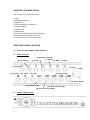
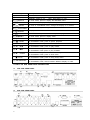
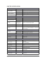
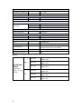
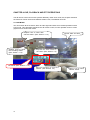
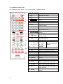
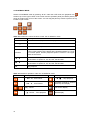
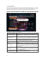
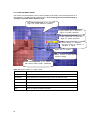
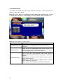
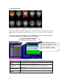
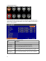
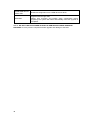
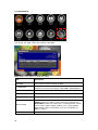
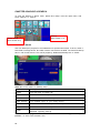
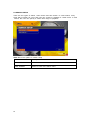
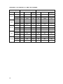
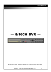
4/8/16 Channel
H.264 DVR
User Manual
This document contains preliminary information and subject to change without notice.
1
Regulatory
FCC Certification
This equipment has been tested and found to comply with the limits for a
class A digital device, pursuant to Part 15 of the FCC rules. These limits
are designed to provide reasonable protection against harmful
interference when the equipment is operated in a commercial
environment. This equipment generates, uses, and can radiate radio
frequency energy and, if not installed and used in accordance with the
instruction manual, may cause harmful interference to radio
communications. Operation of this equipment in a residential area is
likely to cause harmful interference in which case the user will be
required to correct the interference at their own expense.
CE Mark
This product is marked with the CE symbol and indicates compliance with
all applicable EEC directives.
Warning
To prevent fire or shock hazard, do not expose the unit to rain or
moisture.
This symbol alerts the user to the presence of non-insulated dangerous
voltage within the product's enclosure that may be of sufficient magnitude
to constitute a risk of electric shock.
This symbol alerts the user to the presence of important operating and
maintenance (servicing) instructions in the literature accompanying the
product.
2
Contents
CHAPTER 1 PACKING DETAIL………………………………………………………….
6
CHAPTER 2 PANEL LOCATION ………………………………………...................
6
2-1 Front Panel Controls …………………………………………………………………
7
2-2 Rear Panel Connectors ………………………………………………………………
8
CHAPTER 3 SPECIFICATIONS ………………………………………………………..
9
CHAPTER 4 LIVE, PLAYBACK AND PTZ OPERATIONS …............................
11
4-1 Live Mode ……………………………………………………………………………..
11
4-1.1 Remote Controller …………………………………………………………………..
12
4-1.2 Main Screen OSD …………………………………..……………………………..
13
4-2 Playback Mode ………………………………………………………………………..
14
4-3 PTZ Mode ……………………………………………………………………………..
15
CHAPTER 5 SETUP YOUR DVR…………..……………………………………………
17
5-1 Record Setup …………………………………………………………………...........
20
5-1.1 Quality & Frame Rate Setup ………………………………………………….
21
5-2 Event Setup …………………………………………………………………………...
22
5-2.1 Motion Setup …………………………………………………………………...
23
5-2.1.1 Motion Area Setup ……………………………………………………
24
5-2.2 Sensor Setup …………………………………………………………………..
25
5-3 Schedule Setup ………………………………………………………………...........
26
5-3.1 Schedule Record Setup ………………………………………………………
27
5-3.2 Holiday Setup ………………………………………………………………….
27
5-4 Camera Setup ………………………………………………………………………...
28
5-5 Account Setup ………………………………………………………………………...
30
5-5.1 Permission Setup ………………………………………………………………
31
5-6 Networking Setup …………………………………………………………………….
32
5-6.1 Networking Setup ……………………………………………………………...
33
5-6.1.1 DHCP ………………………………………………………………….
34
5-6.1.2 LAN …………………………………………………………………….
35
5-6.1.3 ADSL ……………………………………………………………..........
35
5-6.2 HTTP Setup …………………………………………………………………….
36
5-6.3 DDNS Setup ……………………………………………………………………
36
5-6.4 Mail Setup ………………………………………………………………………
37
5-6.5 MSN Setup ………………………………………………………………………
38
5-7 PTZ & RS485 Setup ………………………………………………………………….
39
5-8 System Setup …………………………………………………………………………
40
5-8.1 Display Setup …………………………………………………………………..
40
3
5-8.2 Date/Time Setup ……………………………………………………………….
41
5-8.2.1 Change Date & Time …………………………………………………
41
5-8.2.2 Time Zone Setup ……………………………………………………..
42
5-8.2.3 Internet Time Setup …………………………………………………..
44
5-8.3 Buzzer & Relay Setup …………………………………………………………
45
5-8.4 SPOT Setup ……………………………………………………………...........
46
5-9 Utility Setup ……………………………………………………………………………
47
5-10 Diagnostic ……………………………………………………………………………
49
CHAPTER 6 BACKUP & SEARCH ………………………………………...
50
6-1 Backup Setup …………………………………………………………………………
50
6-2 Search Setup …………………………………………………………………............
51
6-2.1 Event Search …………………………………………………………………..
52
6-2.1.1 Criteria Setup For Event Search …………………………………….
53
6-2.2 Time Search ……………………………………………………………...........
54
CHAPTER 7 NETWORK SURVEILLANCE ……………………………….
55
7-1 IE Setup ……………….………………………………………………………………
55
7-2 Software Installation and Setup ………………………………………..............
57
CHAPTER 8 MOBILE APPLICATION INSTALLATION AND USAGE….
61
8-1 Mobile Application Installation and Operation for Symbian System……..………
61
8-1.1 Mobile Application Installation ………………………………………….........
61
8-1.2 Mobile Application Operation …………………………………………………
61
8-1.2.1 Add New Login DVR ………………………………………………….
61
8-1.2.2 Logging Onto the DVR ……………………………………………….
62
8-1.2.3 Modify the Login Information of DVR ……………………………….
63
8-1.2.4 Delete the Login Information of DVR ……………………………….
63
8-1.3 Live Monitoring Operation …………………………………………………….
63
8-1.3.1 Scroll the Image ………………………………………………………
63
8-1.3.2 Image Quality Setup …………………………………………............
64
8-1.3.3 Channel Display……………………………………………………….
64
8-1.3.4 Size of Image …………………………………………………...........
64
8-1.3.5 Rotate the Image ……………………………………………………..
65
8-1.3.6 Alarm …………………………………………………………………..
65
8-2 Mobile Application Installation and Operation for Windows Mobile System.
66
8-2.1 Mobile Application Installation ………………………………………………..
66
8-2.2 Mobile Application Operation …………………………………………………
67
8-2.3 Operation Under The Live Monitoring….…………………………………….
68
8-2.3.1 Operation Under The LIVE Monitoring…..………………
68
8-3.2 Mobile Application Operation for Other Systems….……..
69
4
CHAPTER 9 CMS INSTALLATION AND USAGE GUIDE ……………….
70
9-1 CMS Installation ………………………………………………………………………
70
9-2 CMS Login and Environment ………………………………………………………..
73
9-3 Setup your own remote surviellance………………………………………………..
74
9-3.1 User Setup …………………………………………………………………………..
75
9-3.2 DVR Connection ……..……………………………………………………………..
76
9-3.3 Group Setup…… ……..……………………………………………………………..
77
9-3.4 eMap Setup……………………………………………………………………………
78
9-4 Remote Surveillance Management …………………………………………………..
79
9-4.1 View a DVR/Group List………………………………………………………………
79
9-4.2 View Event Logs………………………………………………………………………
80
9-4.3 Main Display……………………………………………………………………………
80
9-4.4 Audio Control……………………………………………………………………………
81
9-4.5 eMap Display……………………………………………………………………………
81
9-4.3 PTZ Control……………………………………………………………………………
83
9-5 Local PC Video Record and Information…………………………………………..
83
9-6 Playback Video …………………………………………………………………………
84
9-6.1 Remote Play …………………………………………………………………...
84
9-6.2 HDD Playback...………………………………………………………………..
85
9-6.3 File Playback …………………………………………………………………..
86
9-6.4 Event Playback…………………………………………………………………
87
9-6.5 Snapshot Data .………………………………………………………………...
88
9-6.6 Recording Data………………………………………………………………..
88
APPENDIX I HARD DISK INSTALLATION ………………………………..
89
APPENDIX II DDNS SETUP ……………………………………..
91
APPENDIX III TROUBLE SHOOTING
96
……………………………………..
APPENDIX IV DVR CHECK LIST FOR 3G/GPRS SUPPORT
………………..
APPENDIX V THE AMOUNT OF TIME FOR STORAGE…………………………..
5
97
98
CHAPTER 1 PACKING DETAIL
The content of the package include:
1. DVR
3. IR Remote Control
4. Batteries x 2
5. CD (User Manual, Software …)
6. Power Adapter
7. Power Cord
8. HDD Screws
9. External Connector (for 16CH DVR only)
10. Camera ×4 (for 4CH DIY kit only)
11. DIY cable ×4 (for 4CH DIY kit only)
CHAPTER 2 PANEL LOCATION
2-1
4/8/16 CH DVR FRONT PANEL CONTROL
4CH Front Panel
(6) Sequence Display
(7) Search
(4) PIP display
(5) Zoom
(8) ESC
(9) Menu
(3) Backup
(10) Record
(2) LEDs
(11) Pause
⑫ Play
⑪ ⑩
(12)
⑨
(1) USB
⑧
(16) Stop⑦(Down)
(17) Enter (Mode)
(13) Rewind (Left)
(15) Slow Forward (Up)
(14) Fast Forward (Right)
6
8/16CH FRONT PANEL
Control Keys
Description
(1) USB 2.0 Port
(2) LED Display
Port for USB external devices.
POWER:Power is on.
HDD:Hard disk is in use.
In LIVE mode, press to display the BACKUP menu.
(3)
BACKUP
(4)
In LIVE mode, display with picture in picture format.
PIP
(5)
In LIVE or PLAYBACK mode, enlarge the display of a channel.
ZOOM
(6)
AUTO SEQ.
(7)
Display the search menu.
SEARCH
(8)
In LIVE mode, cycle through all channels in full screen.
In SETUP mode, press to return to previous page.
ESC
In LIVE mode, press to display menu.
(9)
MENU
(10) ● REC
Start or stop recording.
(11) ▌▌ PAUSE
In PLAYBACK mode, press to pause playback.
(12) ▶ PLAY
Play back in normal speed.
In SETUP mode, press to reduce value.
In PLAYBACK mode, press to play rewind.
In SETUP mode, press to increase value.
In PLAYBACK mode press to play forwards.
In SETUP mode, press to move cursor up.
In PLAYBACK mode, press to slow down.
In SETUP mode, press to move cursor down.
In PLAYBACK mode, press to stop playing back.
In SETUP mode, press to enter values.
In PLAYBACK mode, switch between different display in order.
(13) ⊳
/ ⊳⊳
(14) / (15) / SLOW
(16) DOWN/
■ STOP
(17) ENTER/MODE
2-2 4/8/16 CH DVR REAR PANEL CONNECTORS
4CH DVR REAR PANEL
(1)
(2)
(3)
(6)
(5)
(7)
(11)
(4)
(10)
(9)
(8)
8CH DVR REAR PANEL
(1)
(2)
(3)
(4)
(5)
(11)
(8)
(10)
7
(9)
(7)
(6)
16CH DVR REAR PANEL
(1)
(2)
(3)
(5)
(4)
(10)
(6)
(1) VIDEO OUT
BNC output port for the main monitor.
(2) VIDEO IN
BNC input ports for cameras, 4/8 in total.
(3) AUDIO IN
RCA input port for audio signal.
(4) AUDIO OUT
RCA output for audio signal.
(5) VGA
VGA port.
(6) Camera Power /
ESATA
Power for cameras / external SATA interface for HDD
(7) FUNCTION
(alarm in number
differ for 4/8 DVR)
(8) LAN
(9)NTSC/PAL SWITCH
(10) SPOT MONITOR
(11) Power (DC12V)
(12) EXTERNAL I/O
(16CH DVR only)
8
(8)
(12)
(9)
1:RS-485 A
8:ALARM IN CH2
2:RS-485 B
9:ALARM IN CH3
3:RELAY NO
10:ALARM IN CH4
4:RELAY COM
11:ALARM IN CH5
5:RELAY NC
12:ALARM IN CH6
6:ALARM IN GND
13:ALARM IN CH7
7:ALARM IN CH1
14:ALARM IN CH8
Network port.
Switch between NTSC and PAL format.
BNC port to display full screen image of all installed
cameras in sequence.
Socket for a DC 12V input.
1:GND
14:ALARM IN CH4
2 : GND
15:ALARM IN CH5
3 : RS-485 B
16:ALARM IN CH6
4 : RELAY NO
17:ALARM IN CH7
5:RS-485 A
18:ALARM IN CH8
6:RELAY COM
19:ALARM IN CH9
7 : GND
20:ALARM IN CH10
8:RELAY NC
21:ALARM IN CH11
9:GND
22:ALARM IN CH12
10 : GND
23:ALARM IN CH13
11:ALARM IN CH1
24:ALARM IN CH14
12:ALARM IN CH2
25:ALARM IN CH15
13:ALARM IN CH3
26:ALARM IN CH16
CHAPTER 3 SPECIFICAITONS
1. VIDEO
Input Level
Display Speed
Display Resolution
1.0 Vp-p±10% Composite, 75Ω Balanced
NTSC
480 fps (16CH), 240fps (8CH), 120fps (4CH)
PAL
400 fps (16CH), 200fps (8CH) , 100fps (4CH)
NTSC
720 (H) x 480 (V)
PAL
720 (H) x 576 (V)
Monitor Output
2Vp-p Composite, 75Ω Balanced
2. RECORDING
Compression Method
H.264
Recording Speed
Refer to table 3-1
Recording Resolution
Quality
NTSC
720 x 480, 720 x 240, 352 x 240
PAL
720 x 576, 720 x 288, 352 x 288
Independent for
each channel
Lowest/ Low/ Normal/ High/ Highest
Schedule
Setup by “minute” as unit
Mode
Manual / Event (Motion, Sensor) / Schedule
By resolution, fps and quality
Method
Setup fps and quality separately for normal and
event recording
3. SATA DEVICE
Capacity
Type
Internal Storage
2HDD(8CH/16CH), 1 HDD (4CH)
External Storage
E-SATA(8CH/16CH model only)
SATA / SATAⅡ compatible
4. ALARM
Sensor Input
16 (16CH), 8 (8CH), 4 (4CH)
Alarm Out
1 Relay output
Motion Detection
Available per each camera/ Multi-detection level
5. CONNECTIONS
Video Input
Video Output
BNC 16 ports (16CH), 8 ports (8CH), 4 ports (4CH)
BNC 2 port
VGA 1 port (Option)
Audio Input
RCA x4 (8CH/16CH), RCA x1 (4CH)
Audio Output
RCA x1
USB 2.0
USB memory stick, USB Mouse, USB Touch Panel
Remote
Standard remote control
External I/O
Ethernet
1 RS-485, 16 (16CH) / 8 (8CH) / 4 (4CH) sensor input,
1 Relay Output
1 RJ45 connector, 10/100 Mbps
6. ELECTRICAL
Power Source
9
DC 12V / 5A
7. ENVIRONMENTAL
Operation Temperature
5℃ ~ + 40℃
Humidity
Less than 90%
8. PHYSICAL
Dimension
Varies with different models.
Weight
Varies with different models.
9. BACKUP
BACKUP
USB Stick
Video Data, Audio
DVD-RW
Video Data, Audio
Network
Video Data, Audio
10. SEARCHING & PLAYBACK
Searching Method
Event/ Time
11. MULTI-REMOTE SURVEILLANCE
Monitoring Environment
Web / Client Software (CMS)
Max. client
Supporting multi-client (5 clients accessible)
12. OTHERS
OS
Embedded Linux
Multi Task
Pentaplex
Live、Record、Playback、Network、Backup
Front Keys / Remote Control
Control Device
Virtual Keyboard / Mouse / AP Software
PC Viewer
Direct viewing of DVR’s HDD on PC
Numbers of event list
9999
Table 3-1
352 x 240
NTSC
RECORDING
SPEED
720 x 240
720 x 480
(Independent
setting for each
channel)
352 x 288
PAL
720 x 288
720 x 576
10
240fps / 16CH, 8CH
120fps / 4CH
120fps / 16CH, 8CH
60fps / 4CH
60fps / 16CH, 8CH
30fps / 4CH
200fps / 16CH, 8CH
100fps / 4CH
100fps / 16CH, 8CH
50fps / 4CH
50fps / 16CH, 8CH
25fps / 4CH
CHAPTER 4 LIVE, PLAYBACK AND PTZ OPERATIONS
The IR remote control and mouse operate differently under each mode; this chapter describes
the functions of them under three different modes: LIVE, PLAYBACK and PTZ.
4-1 LIVE MODE
You can monitor all the channels, listen to audio signal and have some related operations under
LIVE mode. This paragraph describes the IR remote control, mouse operation and on screen
graphical icons under LIVE mode.
Graphic icons to show each
camera status. (See Section 4-1.2)
Graphic icons to show
the recording status.
(See Section 4-1.2)
The Menu (See Section 4-1.2)
11
Current date and time.
Playback the video stored in
the DVR. (See Section 4-2)
Use PTZ function to move the
camera. (See Section 4-3)
Graphic icon to show
network status.
4-1.1 REMOTE CONTROLLER
The meaning for each button on the remote control is explained below:
Table 4-1.1 Remote control functions under the LIVE mode
1
2
Button Name
Description
1. REC
Start/Stop recording.
3
2.
Audio
4⁄ 5
6⁄ 7
3. ◀◀
8
▌▌
■
▶▶
4. BK-UP
5. STATUS
6. SLOW
9
10
8.1,2…7,8,9, +10
11/12
10.
LOCK
11. PLAY
14/15
12
slow-down
Select the channel to monitor in full
screen from 1 to 16
Switch to Quad∕9∕13∕16 channel
display
Enable/Disable the keypad function
on the front panel, the remote control
and the mouse.
Start playing back the most recently
recorded segment.
14. MENU
15. ESC
Return to the previous mode.
16. Z+∕Z-
PTZ zoom-in∕out.
17. IRIS +∕-
PTZ iris-open∕close.
13.
22⁄23
24⁄25
to
Display search menu.
:Up
:Down
Direction and ENTER
:Left
buttons.
:Right
ENTER
Display setup menu.
12. T-SRH
16
17
18
19⁄20
21
Press this button
playback speed
7. MODE
9.
13
Fast forward ; Pause ; Stop ; Fast
rewind
Display backup menu.
Display status.
18. F+∕-
PTZ focus-in∕out.
19. OSD
Turn on∕off the screen display.
20. PRESET
Preset
21. PTZ
Start/Stop PTZ control.
22. AUTO
In AUTO mode, all available channels
will be cycled through in full screen.
23. FREEZE
Turn on/off screen freeze function
24. PIP
Turn on picture-in-picture format. Click
on the channel name can switch to
other channels.
25. ZOOM
Enable/Disable double screen size
display.
4-1.2 MAIN SCREEN OSD
Table 4-1.2 Graphical icons appeared after right-click on the mouse under LIVE mode.
Icon
Description
Icon
Description
Setup
Pause
Main Menu
PIP, picture in picture
Search Setup
ZOOM, double the screen size
Backup
Auto-Sequence
PTZ Control
LOCK, activate the key lock.
Record On∕Off
Full Screen
Playback
Quad Display
Display Setup
Table 4-1.3 Description for camera status in LIVE mode
Icon
Description
Icon
Video loss detected on the
channel
Motion detected on the channel
Sensor triggered on the
channel
Description
number
No event happening
Table 4-1.4 Description of on screen graphical icons in LIVE mode
Icon
Description
Icon
Remote user currently logging
into DVR
Timer recording is on
Red:Timer is set and recording
has been started
White:Timer is set but recording
has not yet been started
Recording is on
Audio is on
Audio is off
Auto-Seq is on
USB device detected
DVD burner is detected
Lock is on
PTZ control is on
13
Description
2X
2X zoom in is on
Pause is on, screen is frozen
4-2 PLAYBACK MODE
Switch to PLAYBACK mode by pressing “PLAY” under the LIVE mode, the graphical icon
will show up on the upper center of the screen and the operation panel (see below picture) will
show up at right lower corner of the screen. You can drag the panel by mouse to place it on any
location of your screen.
Table 4-2.1 Remote control functions under the PLAYBACK mode
Button
Description
ENTER∕MODE
Switch to full screen, quad channel display.
MENU∕▌▌
Turn on∕off PAUSE.
PLAY
Play back at normal speed.
▲∕SLOW
Play back at slower speed. The speed will be slowed to 1/2, 1/4, 1/8,
1/16 by each pressing of the button till the slowest limitation of 1/16 of
the normal speed. Current playback speed is shown in the upper
center of the screen.
▶▶∕▶
Fast rewind. Each press increases the speed to the next level. There
are six kinds of speed: 2x, 4X, 8X, 16X, 32X and 64X.
◀◀∕◀
Fast forward. Each press increases the speed to the next level. There
are six kinds of speed: 2x, 4X, 8X, 16X, 32X and 64X.
▼∕■
Stop playback.
Table 4-2.2 Mouse operation under the PLAYBACK mode.
Icon
Description
Icon
Description
/
14
「◀◀/◀」Fast rewind
「▼/■」, Stop playback
「▶▶/▶」Fast forward
Playback channel by channel
with snap shot display
Play/Pause
Full screen display
「▲/SLOW」, Slow playback
Quad display
4-3 PTZ MODE
Switch to the PTZ mode by pressing “PTZ” button under the LIVE mode. The PTZ icon
will
appear on upper left of the screen but it can be re-located on any place of your screen by
dragging the mouse.
Table 4-3.1 Remote Control functions under the PTZ mode
Button
Description
▲/SLOW
Move PTZ up.
▼/■
Move PTZ down.
◀◀/◀
Move PTZ to the left.
▶▶/▶
Move PTZ to the right.
ZOOM +
PTZ zoom-in.
ZOOM -
PTZ zoom-out.
FOCUS +
PTZ focus-in.
FOCUS -
PTZ focus-out.
IRIS +
PTZ iris-open.
IRIS -
PTZ iris-close.
PRESET+
NUMBER
Setup the Preset location ; P ress “PRESET” key first then two-digit
number; DVR will set the current PTZ location at entered preset number.
PLAY+
NUMBER
Go to Preset location; Press “PLAY” key first then two-digit number, PTZ
will go to the correspondent preset number location.
15
Table 4-3.2 Mouse operation under the PTZ mode
Icon
Description
Leave PTZ Mode, back to the LIVE mode.
Pre-set number N. (1~64).
Go to pre-set number N.
Set current PTZ location at pre-set number N.
To move PTZ in 360°.
PTZ zoom in; PTZ zoom out.
PTZ focus in; PTZ focus out.
PTZ IRIS open, PTZ IRIS close.
Below functions need support from specific PTZ manufacturer.
Please check user manual of your PTZ for more details.
AUX 1, 「AUTO」key + Number Key「1」
AUX 2, 「AUTO」key + Number Key「2」
AUX 3, 「AUTO」key + Number Key「3」
AUX 4, 「AUTO」key + Number Key「4」
AUX 5, 「AUTO」key + Number Key「5」
AUX 6, 「AUTO」key + Number Key「6」
AUX 7, 「AUTO」key + Number Key「7」
AUX 8, 「AUTO」key + Number Key「8」
「Backup」, Customized function.
16
CHAPTER 5 SETUP YOUR DVR
Before you Start
Please install the hard disk. The detail of installation is introduced in Appendix I. To setup your
DVR, Please follow the steps below:
(1) Login to the DVR and enter the main menu. Please refer to the content below.
(2) Setup the time and date. Please refer to section 5.8.
(3) Format the hard disk. Please refer to section 5.9.
(4) Setup the record schedule. Please refer to section 5.1 ~ 5.3.
Please also refer to the CD for video tutorial, which will help you get on hand in shortest time.
Login
To enter the main menu and set up DVR, log-in account and user password are required.
The default password of the administrator is “123456”. Please check the “ACCOUNT SETUP”
for related setup of other log-in users.
Table 5-0.1 Definition of the virtual keyboard.
Item
Description
Switch between capital and small letters.
/
Switch between numbers and letters.
Press to cancel the setup, and re-choose the login account.
Delete the last character.
Enter to identify the password. It will enter the setup menu, if the
password is verified.
17
Quick Menu
Right click with the mouse, or press the “menu” button on the front panel, and the quick
menu will be shown on the display screen. Quick menu provides most common
function for users, eg, playback, full screen display, quad display, etc.
Playback
(See Section 4.2)
Record On/Off *
Display
Setup
Full Screen Display
Setup
Move your mouse
here to setup!
Quad
Display
*Record On/Off: If record is set “On”, the record mode will be determined by Record
Type in section 5.1.1. If the record is set “Off”, the record mode will be determined by
the schedule setting.
Setup
This provides the setup menu for users. This includes the main menu, for configuration,
search setup, backup setup and PTZ setup.
Click here
to setup
Main Menu
(See Section 5.1~5.10)
Search Setup
(See Section 6.2)
Backup
(See Section 6.1)
18
PTZ Setup
(See Section 4.3)
Main Menu
The main menu provides 10 basic setting for DVR. The detail for each basic setup, will
be described in the following sections. Note that to start DVR recording, please
(1) go to utility setup and format the HDD and (2) go over recording setup, event
setup, as well as schedule setup.
Schedule Setup
Event Setup
Camera Setup
Account Setup
Record Setup
Network Setup
PTZ & RS485 Setup
System Setup
Table 5-0.2 The operation of remote control under the setting menu
Item
Description
⊳
Switch to different options under the one item.
Switch to different items.
MENU
Save setup and back to LIVE mode.
BK-UP∕ESC
Back to Upper level of menu without saving.
ENTER
Enter the menu, or display virtual keyboard.
19
Diagnostic
Utility Setup
5-1 RECORD SETUP
Record setup enables the users to enable or disable the recording modes, as well as
the recording quality and frame rate. Please click on the recording modes you wish to
enable.
Note that, to enable motion detection or sensor detect in schedule, please enable
(1) ”Schedule – Motion” and “Schedule - Sensor”, as well as (2) enable these
function in the event setup. For detail, please refer to Section 5-2.1 on motion
detection and Section 5-2.2 for sensor.
Table 5-1.1 The options in record setup
Item
Description
HDD FULL
Select STOP to stop recording or OVERWRITE to reuse the
HDD when HDD is full
「STOP」
:Stop recording when HDD is full.
「OVERWRITE」
:Start to overwrite that begin from the oldest
data of HDD, and continue to record.
RECORD NORMAL
Enable∕disable normal recording
20
RECORD MOTION
Enable∕disable recording while motion is detected
RECORD SENSOR
Enable∕disable recording while sensor is triggered
PRE ALARM RECORD
Enable∕disable pre-event recording while motion or sensor is
triggered but not in the recording mode. The pre-recording time
is approximate at 10 seconds (16 MB).
AUDIO RECORD
Enable∕disable audio recording.
QUALITY & FRAME
RATE SETUP
Setup the quality and frame rate for each channel under normal
recording and event recording type.
5-1.1 QUALITY & FRAME RATE SETUP
User can adjust the resolution for the cameras. User can also adjust the quality, as well
as the frame rate of each individual camera. FPS stands for Frames Per Second, and
as the value increase, the video will be smoother.
Table 5-1.2 The options in quality & frame rate setup
Item
Description
RESOLUTION
Choose record resolution from:CIF∕ Half D1 (2CIF)∕ D1.
RECORD TYPE
You can choose from normal recording or event recording
NO.
Check∕uncheck the box will enable∕disable recording on the
channel.
QUALITY
Choose from Lowest∕Low∕Normal∕High∕Highest.
FPS
Choose recording frame rate.
21
5-2 EVENT SETUP
There are two types of events. First is the motion event which detects the movement
in each camera. Second is the alarm event which detects the alarm input from alarm
sensors. Users can adjust the alarm duration (in other word the record time) for the
detected event.
Table 5-2.1 The options in event setup
Item
Description
ALARM DURATION (SECONDS)
Set up alarm duration in seconds.
Drag the white bar or press ⊳ to adjust value.
MOTION SETUP
Enter to set up motion detection.
SENSOR SETUP
Enter to set up sensor detection.
22
5-2.1 MOTION SETUP
Users can enable or disable the functions of motion detection and popup. The cameras
can also be setup individually on sensitivity (this means at what level the camera is to
determine the movement as a motion), and the region that requires detection.
Note that to use motion detection by schedule, you must enable this function here,
as well as enable this function in record setup. For detail, please refer to Section
5-1.
Mark Motion Detection to
make sure it works!
Table 5-2.2 The options in motion setup
Item
Description
MOTION DETECTION
Check the box to enable∕ disable m otion d etection for all
channels.
MOTION POPUP
Check the box to enable∕disable popup screen function for all
channels. When motion is detected in LIVE mode, the
detected channel image will pop up in full screen display.
1~4
You can setup independently for each channel.
SELECTED CHANNEL
TURN
Check the box to enable∕disable motion detection for each
channel.
Drag the white bar or press ⊳ to set up Object Size from
value 1 to 15 for each channel. The lower value you set the
higher sensitivity it will be. Value set up as 1, the motion will be
detected easiest.
OBJECT SIZE
SENSITIVITY
Drag the white bar or press ⊳ to set up Sensitivity from
value 1 to 15 for each channel. The lower value you set the
higher sensitivity it will be
MOTION AREA SETUP
Enter to setup motion detection area
23
5-2.1.1 MOTION AREA SETUP
The motion area setup allows users to select multiple areas where camera should watch for m
otion detection. The default area is entire screen. Click and drag the cursor without lifting to
mark your selected motion detection area.
The blue background is the selected
region for motion detection. [Select]
Press “Select All” to select the
region for motion detection.
Press “Select All” to select the
region for motion detection.
Press “Select” or “Deselect”,
and use mouse to “Select” or
“Deselect” a region.
Press “OK” to confirm.
Press “Cancel” to keep the
previous setting
The red background is the region
that cannot detect motion. [Deselect]
Table 5-2.3 The options in motion setup
Item
Description
LOCK∕ZOOM
Press LOCK∕ZOOM to select entire screen as detection area.
MUTE∕PIP
Press MUTE∕PIP to deselect entire screen as detection area.
STATUS
Switch between “SELECT” and “DESELECT” for cursor-dragging function.
ENTER
Press to function on the selected area with assigned status.
MENU
Press to save the setup and leave.
ESC
Press to cancel the setup and leave.
24
5-2.2 SENSOR SETUP
This enables or disables the alarm sensor detection and popup. It also determines the
polarity of each alarm sensor.
Note that to use sensor in schedule, you must enable this function here, as well
as enable this function in record setup. For detail, please refer to Section 5-1.
Mark Sensor Detection to
make sure it works!
Table 5-2.4 The options in sensor setup
Item
Description
SENSOR DETECTION
Check the box to enable∕disable sensor detection for all
channels.
SENSOR POPUP
Check the box to enable∕disable popup screen function for all
channels. When sensor is detected in LIVE mode, the detected
channel image will pop up in full screen display.
SENSOR POLARITY
Click or press ▼ to select between HIGH, LOW voltage for
triggering sensor detection or OFF to turn off the sensor for each
channel
LOW Polarity:Sensor has not been triggered. When connected,
sensor will be turned on.
HIGH Polarity:Sensor has been triggered. When connected,
sensor status will be turned off.
OFF:Sensor is deactivated, and will not be turned on∕off.
25
5-3 SCHEDULE SETUP
Setup the schedule is required to command the DVR to record.
Except from starting recording manually, you can also setup the recording time by weeks.
The schedule arrangement includes normal, motion detect, and sensor detect recording
type.
You can overlap normal recording, motion recording or alarm recording by setting
up several schedules and enable each of the schedules.
Yellow is the selected schedule.
The selection is done by mouse.
Green: The schedule is set. It is
available in the selected schedule.
White: The schedule is set. It is not
set in the selected schedule.
Black: The schedule is not set.
Table 5-3.1 The options in schedule setup
ITEM
DESCRIPTION
Click or press ▼ to select Page. Each page provides 10
PAGE
schedules for setup. 5 pages in total.
To enable each schedule, please mark on them. To adjust the
SCHEDULE
content of each scheduling, please click on the option.
(See 5-3.1)
Enter to setup holiday, up to 50 days, other than weekends.
HOLIDAY SETUP
(See 5-3.2)
VIEW EVENT
View Normal/ Motion / Sensor Setup
SETUP
26
5-3.1 SCHEDULE RECORD SETUP
Click on the time on the left side. The setup menu will be displayed. You can have detail setup
by date, time and event. Please remember to click “Enable” to activate the schedule.
Click to enable the schedule!
5-3.2 HOLIDAY SETUP
Since holidays are different by different country and region, you can setup the holiday of your
location accordingly. The orange days are the selected holidays. The maximum number of
days you can select are 50 days.
Click to choose different months
27
Click to select the day as holiday
5-4 CAMERA SETUP
The camera setup can adjust the display and volume for each individual camera.
Table 5-4.1 The options in camera setup
Item
Description
1~4 (4 Channel)
1~8 (8 Channel)
1~16 (16 Channel)
You can setup independently for each channel.
MASK
Check the box to enable∕disable mask function for LIVE mode
BRIGHTNESS
Drag the white bar or press ⊳ to adjust the brightness of your
camera from value 1 to 255. The default value is 128.
CONTRAST
Drag the white bar or press ⊳ to adjust the contrast of your
camera from value 1 to 255. The default value is 128.
SATURATION
Drag the white bar or press ⊳ to adjust the saturation of your
camera from value 1 to 255. The default value is 128.
28
HUE
NAME
VOLUME
Drag the white bar or press ⊳ to adjust Hue of your camera from
value 1 to 255. The default value is 128. (This function is not
supported at PAL system.)
Set up name of each channel. To ensure the name is read easily,
it is suggested to use less than 30 characters.
Select to adjust the audio input volume in live mode for several
channels under LIVE mode and recording mode.
4 Channel DVR: CH1 *
8/16 Channel DVR: CH1~CH4 *
* Note: The audio recorded is tied with the camera. For example, Audio 1 is recorded
with the video in Camera 1.
29
5-5 ACCOUNT SETUP
The Account Setup menu is used to provide role-based permission independently setting for
each user (maximum of 4 users) to access DVR over network. The default admin account is
「admin」and password is “123456”. You can register new accounts for users by setup
user name, password, permission list, and remember to click on the No. to activate
the account,
Remember to mark No. to
activate the account.
Table 5-5.1 The options in account setup
Item
Description
AUTO LOCK
Setting
Key lock
Function
Auto Logout *
Key Lock **
○***
○
Key unlock
○
X
Disable
X
X
NO.
Check to activate the user’s account.
PASSWORD
Enter to set up password for each user. Password MUST be set up to 8
characters mixed by letters and numbers with case-sensitive.
30
PERMISSIONS
Enter to set up Permissions for each user.
CHANGE ADMIN
PASSWORD
Enter to change administrator’s password. The number of characters
is no restricted.
* In the status “logged out automatically”, you will have to operate in limited authority.
You can only use basic function such as operations like: freeze the screen, picture in
picture, zoom in∕out, switch between channels…etc. If you need to enter the setup
menu, search menu, backup menu, record…etc, you will need to enter user account
and password.
** In the status “key lock automatically”, remote control and mouse can’t function before
entering the user account verified password.
***「○」: Enable the function, 「X」: Disable the function
5-5.1 PERMISSION SETUP
The Account Setup is set to provide individual user (maximum of 4 users) role-based
permissions, including access to setup menu, network operation, PTZ function, playback, utility,
backup and mask on specific channels while playing back.
31
5-6 NETWORKING SETUP
In the networking setup, the user is required to determine the network type of the
network used, and the configurations for it. Users can also setup the HTTP server for
Internet Explorer connection, setup DDNS for the usage of DDNS, and setup mail
server for email notification.
Table 5-6.1 The options in networking setup
Item
Description
CONNECT TYPE
Setup mode for network connection:DHCP、LAN、ADSL.
HTTP SETUP
Enter to set up HTTP for remote access into DVR.
DDNS SETUP
Enter to enable∕disable DDNS function and set up.
MAIL SETUP
Enter to enable∕disable Email notification and setup. There are up to
10 email addresses can be notified with different event options.
MSN SETUP
(8CH/16CH Model)
Enter to setup MSN notification, when an event is triggered.
32
5-6.1 NETWORKING SETUP
The DVR supports DHCP, LAN and ADSL accesses for network connection. If the settings are
subsequently changed, pressing “PLAY” button to drive new settings for re-connection is
required.
LAN - STATIC IP
Public Static IP Connection
Public Static IP (LAN port for Router)
Eg. IP: 61.201.78.21
Mask: 255.255.255.248
or SWITCH
Public Static IP
Eg. IP: 61.201.78.22
Mask: 255.255.255.248
Private / Virtual IP Static IP Connection
Public Static IP (WAN port)
Eg. IP: 61.201.78.21
Mask: 255.255.255.248
Private Static IP
Eg. IP: 192.168.1.20
Mask: 255.255.255.0
Static IP is considered as a fixed IP assigned by ISP (Public IP) or IP share device (Virtual IP).
DVR connecting to static IP needs to be assigned IP address, Gateway, and Subnet mask.
33
DHCP
The DHCP functions needs to be supported by a router or a cable modem network with DHCP
services. It is preferable to use DDNS at DHCP connection. Note that port mapping is required
if needed to connect the DVR outside the LAN.
Public Static IP (WAN port)
Eg. IP: 61.201.78.21
Mask: 255.255.255.248
ADSL
Private Dynamic IP
(LAN port)
Eg. IP: 192.168.1.20
(assigned by Router)
Mask: 255.255.255.0
Dynamic IP Configuration
IP: 192.168.1.1
Mask: 255.255.255.0
Setup DDNS setting
The ADSL function needs to have one “username” and one “password” subscribed from one
ISP supplier. Please set up username and password for ADSL connection.
PPPoE mode
DDNS configuration
Enable DDNS on DVR
Username: jack/ Password: jack
5-6.1.1 DHCP
If the DHCP option is used for DVR network connection, an IP address is assigned by the
DHCP server automatically.
34
5-6.1.2 LAN
To setup static IP address, please select “LAN” for network connection, and the following
information, including IP address, Subnet Mask, Gateway and DNS, is required.
Table 5-6.2 The options in LAN setup
Item
Description
IP ADDRESS
Enter IP address provided by ISP
SUBNET MASK
Enter IP address of Subnet Mask provided by ISP
GATEWAY
Enter IP address of Gate way provided by ISP
DNS
Enter DNS address provided by ISP. (Note:The correct DNS address
must be entered for DDNS function).
5-6.1.3 ADSL
Select ADSL for network connection, the following information, including user name and
password, is required.
Table 5-6.3 The options in ADSL setup
35
Item
Description
USER NAME
Enter user name provided by ISP
PASSWORD
Enter password provided by ISP
5-6.2 HTTP SETUP
To enable IE to connect to the DVR, user is required to enable HTTP server. The
default port for IE is 80.
Table 5-6.4 The options in HTTP setup
Item
Description
ENABLE HTTP
SERVER
Check to enable HTTP server. Users can remotely access into the
DVR over the network if the HTTP function is activated.
PORT
Enter a valid port value from 1 up to 65000. The default value is 80.
5-6.3 DDNS SETUP
To use DDNS, please enable the DDNS function, and choose the DDNS server that is
used. To apply DDNS, please check appendix II for detail.
36
Table 5-6.5 The options in DDNS setup
Item
Description
ENABLE DDNS
Check∕uncheck to enable∕disable DDNS function.
DDNS SERVER
Enter the registered SMTP server:
DYNDNS.ORG、NO-IP.ORG、CUSTOM.COM
SMTP SERVER
Enter the registered SMTP server.
USER NAME
Enter user name.
PASSWORD
Enter password.
5-6.4 MAIL SETUP
E-mail can be used as a form of notification when an event occurs (VLOSS, MOTION,
SENSOR). Please enable e-mail notification to use this function, and fill in related
information, including the SMTP server, user name, password and email of the sender,
as well as the receiver’s email.
Table 5-6.6 The options in mail setup
Item
Description
ENABLE
E-MAIL
NOTIFICATION
Check the box to enable∕disable E-mal Notification function.
SMTP SERVER
Enter to set up SMTP server name.
USER NAME
Enter to set up user name.
PASSWORD
Enter to set up password.
SENDER E-MAIL
Enter to set up e-mail address of sender.
E-MAIL ADDRESS
Enter to set up e-mail addresses for up to 10 receivers individually.
TRIGGER EVENT
Enter to select events to send out e-mail notifications when below
circumstances happen:Motion, Sensor and Vloss (Video Loss).
37
5-6.5 MSN SETUP (8CH/16CH Model Only)
MSN setup is used to provide MSN notification when an event is triggered, eg. motion
event or alarm event.
This is the MSN account
and the password to send
the notification on an event.
This is the MSN account to
receive the notification on an
event.
Item
Description
ENABLE MSN
NOTIFICATION
Check∕Uncheck to enable∕disable MSN notification.
MSN ACCOUNT
MSN account to be logged in.
PASSWORD
Account password to log into MSN.
MSN RECEIVER
MSN account to receive event notification messages.
38
5-7 PTZ & RS485 SETUP
The DVR allows users to control PTZ function of your camera. To enable PTZ function, the 485
cable should be connected to the RS-485 port of DVR.
Table 5-7.1 The options in PTZ and RS485 setup
Item
Description
ENABLE PTZ
Click the box to enable∕disable PTZ function for each channel.
PROTOCOL
Set up the protocol of PTZ cam. The supported protocol are
PELCO-P, PELCO-D, KND, LI-LIN.
PTZ ID
Click or press ⊳ to set up PTZ ID. The valid ID value is from 1 to
64.
BAUD RATE
Select baud rate for PTZ from 2400、4800、9600
39
5-8 SYSTEM SETUP
The system setup provides basic settings, including (1) OSD display, (2) date and time,
(3) buzzer, (4) language, and others.
Table 5-8.1 The options in system setup
Item
Description
DVR NAME
The name of DVR will be shown when users login from remote access.
DVR LOCATION
The location of DVR will be shown when users login from remote
access.
LANGUAGE
Click or press ▼ to select OSD language from English, Chinese, Greek,
Italian, Japanese, Portuguese, Spanish, German, French, Russian or
Polish.
AUTO-SEQ. INTERVAL
( SECONDS)
Click or press ⊳ to setup duration time in seconds for the interval
between channels under Auto-Seq. mode.
40
REMOTE ID
The default remote ID is 0, when DVR is controlled by standard remote
controller.
DISPLAY SETUP
Enter to setup Display
DATE/TIME SETUP
Enter to setup Date/Time
BUZZER
SETUP
Enter to setup Buzzer & Relay
&
RELAY
SPOT SETUP
Enter to setup Spot
5-8.1 DISPLAY SETUP
Item
Description
OSD
Turn on∕off OSD display
DVR STATUS
Turn on∕off DVR illustration and record status display
DATE/TIME
Turn on∕off date and time display
MESSAGE
Turn on∕off message display
CHANNEL NAME
Turn on∕off channel name display
BORDER SET
Set up the color of border in LIVE1, PLAYBACK mode.(black、dark
grey、light grey、white)
41
5-8.2 DATE/TIME SETUP
This provides retrieving the time from Internet, and adjustments for the time zone, date
and time.
Table 5-8.3 The options in date/time setup
Item
Description
HOUR FORMAT
12HOURS∕24HOURS
DATE FORMAT
MM-DD-YY∕DD-MM-YY∕YY-MM-DD
DATE/TIME POSITION
Choose the position of time and date display
CHANGE DATE & TIME
Setup time and date of DVR
TIME ZONE SETUP
Setup GMT and daylight saving time.
INTERNET TIME SETUP
Setup automatic synchronization with internet server
5-8.2.1 CHANGE DATE & TIME
Users are allowed to setup date and time of DVR manually according to your local time.
42
5-8.2.2 TIME ZONE SETUP
In time zone setup, users can change your time zone and activate daylight saving time function
according to your DVR location.
Table 5-8.4 The options in time zone setup
Item
Description
SELECT TIME ZONE
Enter to modify GMT from GMT- 13 to GMT+ 13
DAYLIGHT SAVING TIME
Turn on∕off daylight saving time
43
5-8.2.3 INTERNET TIME SETUP
Synchronize your DVR time with internet time server.
Table 5-8.5 The options in internet time setup
Item
Description
AUTOMATIC
SYNCHRONIZATION
Check to enable DVR automatic synchronization function.
Effective by this option selected, DVR will automatically
synchronize the time upon rebooting or by every 24 hours after
booting.
UPDATE NOW
Date and time show on DVR will immediately correspond with
those in internet server.
44
5-8.3 BUZZER & RELAY SETUP
Table 5-8.6 The options in buzzer & relay setup
Item
Description
KEY TONE
Enable∕disable keystrokes.
RELAY SWITCH
CONNECTION
Set relay signal to be Normal Close (N.C.) or Normal Open (N.O.).
BUZZER DURATION
Set up the duration from 1~999 seconds.
ALARM BUZZER
Enable∕ d isable buzzer operation when the alarm is triggered for
sensor, motion and Vloss (Video Loss).
ALARM RELAY
Enable∕disable the signal to be sent to the RELAY OUT blocks when
the alarm is triggered for sensor, motion and Vloss.
45
5-8.4 SPOT SETUP
The DVR has two modes of video output; one is main video output, the other is spot video
output. SPOT setup is for controlling the order of channels the system cycles through in SPOT
mode. User can monitor every channel in the SPOT mode.
Table 5-8.7 The options in buzzer & relay setup
Item
Description
SPOT MODE
Channels display in spot for three different modes:
MANUAL:Select channels to display manually.
SEQUENCE:Auto-sequence for all channels in order.
EVENT:Display channels with event occurred.
INTERVAL
(SECONDS)
The duration time in seconds for the interval between channels under
SPOT mode.
SKIP VIDEO LOSS
CHANNEL
Whether to skip channels without video signal.
46
5-9 UTILITY SETUP
This is used to reset or upgrade the system, including the HDD, DVR, USB device.
Table 5-9.1 The options in utility setup
Item
HDD INITIALIZATION
USB INITIALIZATION
Description
Select to enter initialize hard disk menu. Please stop recording before
entering this menu. Enter the menu, system will show all the data
(model, volume) of HDD that installed in DVR. Check the HDD you
would like to initialize then press “START”. HDD initialization is
succeeded when the status shows “SUCCEED”.
Clean up all data on USB. Enter USB initialization and press YES to
clean up all data on your USB. The initialization is done when it’s
showed “SUCCEED”.
SYSTEM RECOVERY
Restore system default values
RESET SYSTEM
EVENTS
Reset all the recording events in DVR.
COPY SETUP TO
USB
Copy configuration to a USB device. There will be a file named
“sdvr.config” on your USB.
47
DOWNLOAD SETUP
FROM USB
Download configuration from a USB device into DVR.
UPGRADE
Upgrade DVR through USB.
Please stop recording and backup setup configuration before
upgrading.The system will reboot automatically when the upgrade is
completed.
Notice! DO NOT TURN OFF POWER OR UNPLUG USB DEVICE DURING UPGRADE
PROCESS as it may cause incomplete firmware upgrade and damage to the DVR.
48
5-10 DIAGNOSTIC
This shows the DVR, HDD and network information.
Table 5-10.1 The options in diagnosis setup
Item
Description
VERSION
The current firmware version of DVR
IP ADDRESS
The connected IP address of DVR. If disconnected from
network, the screen will display “NETWORK DISCONNECT”.
MAC ADDRESS
MAC Address of DVR
HDD VOLUME
The capacity of HDD
HDD USED RATE
Percentage of space used on HDD.
HDD STATUS
Shows HDD status.
USING means the HDD is being used for recording now
GOOD/BAD means the HDD has a known/unknown format
for the DVR. (Note: Please initialize your newly-installed
HDD before using it, otherwise it can be recognized as
BAD by DVR.)
FORMAT TIME
The latest format time of HDD
49
CHAPTER 6 BACKUP & SEARCH
To enter the backup or search menu, please find “setup” from the quick menu, and
press “backup” or “search”.
Backup
(See Section 6.1)
Search Setup
(See Section 6.2)
6-1 BACKUP SETUP
User can backup any segment of recorded data in a specified time frame. To do so, either a
DVD-R/W or storage device, like USB, must be connected to the DVR. The format of backup
file is in IRF format and the file can be played by “DVRemoteDesktop.exe” or “iCMS”.
Table 6-1.1 The options in backup setup
Item
Description
FROM
The start time of backup file
TO
The end time of backup file
DEVICE
Select USB etc. as the backup device
FREE SPACE
The available space in your backup device
REFRESH
Recalculate the available space of backup device
CALCULATE
Calculate the size of backup file
Start backup operation. Be sure to calculate the size of backup file
BEFORE operating backup.
Notice!Do not unplug the USB device or turn off the DVR during the backup
process to avoid unrecoverable error.
START
50
6-2 SEARCH SETUP
There are two types of search, event search and time search. In event search, every
event will be shown as a list, and user can choose to playback a certain event. In time
search, the user can specify a certain time range to playback.
Table 6-2.1 The options in search setup
Item
Description
EVENT SEARCH
Press to enter event search menu
TIME SEARCH
Press to enter time search menu
51
6-2.1 EVENT SEARCH
The DVR automatically records events with type, time and channel information included. If there
is recording data for an event, the recording signal
will be shown on the left side of time
information. Rest your cursor under the line and press “ENTER”, or left click your mouse to
playback the recording data.
Item
Description
CRITERIA
Setup conditions of event search
PAGE
Convert pages of events
DATE/TIME
Date/time when event occurred.
Event type, defined as following
EVENT TYPE
CHANNEL
52
VLOSS
Video Loss
MOTION
Motion Detected
SENSOR
Sensor Detected
REMOTEIN
user log-in over the network
REMOTEOUT
user log-out over the network
POWER ON
System Rebooting
KEY LOCK
System key are locked
KEY UNLOCK
System key are unlocked
HDD FULL
HDD is FULL
The channel where event occurred.
6-2.1.1 CRITERIA SETUP FOR EVENT SEARCH
The amount of events can be a lot. Therefore, you can facilitate event sorting by setting up
“CRITERIA”. Setup “Start time”, “End time” and “Event type” for event search, and the search
result will be limited to this specific period of time. Only checked events and channels will be
sorted in event search as well.
53
6-2.2 TIME SEARCH
TIME SEARCH can search for the specific time of recording data to playback. To specify a date,
use ◀ or ▶ to move the cursor up and down, use ▲▼ or roll the mouse to change dates.
Press “ENTER” or left click on the desired date to playback. Note that dates with recording data
are marked with a red square “ □ “ System will start playing back according to the date you
selected. Calendar will be shown by using mouse to click on YEAR and MONTH.
Click DATE to display recording time of that specific date with time bar. You can change time
(hour∕minute∕second) or click on a specific time of time bar by mouse then press “YES”. DVR
will playback the selected recording data.
Pull the time bar with
a mouse to select a
specific time region.
Press “Enter” or left
click with a mouse to
playback video.
54
Press ▲ or ▼ to move the
cursor and select either hour,
minute, second etc. Press ◀
or ▶to change the values.
CHAPTER 7 NETWORK SURVEILLANCE
7-1 IE SETUP
(1) Prework: Before you use, make sure you have enabled the active X program to
download and run on your computer. Please note that some anti-virus program may
block the connection. If this happens, we suggest you to use the AP (remote desktop)
for surveillance. (See Section 7-2)
Enable Active X: In your IE, choose “Tools”, and go to “Internet Options”. The
window below will appear. Choose “Security”, select Custom level, and configure the
activeX conditions as below.
Please configure these two conditions as
“Enable” or “Prompt”.
Deactivate the Anti-Virus Program: Please deactivate the web page protection in
your antivirus program.
(2) Login DVR with IE
Step One:Enter the IP address of DVR in IE browser. Here you may choose to setup
IE remote or download the AP software.
55
Step Two:
:Click OK when window prompts to install an ActiveX for IE remote desktop.
After Installation, please enter the user name and password. Default user name is
admin and password is 123456. Other related setup about user account and password,
please check “5-5 ACCOUNT SETUP“.
Step Three:
:Please enter information of login DVR: IP, port, user name and password,
or choose “PLAY RECORDED FILE” to open backup files in your PC.
Step Four:
:You’ve logged into the DVR
56
7-2 SOFTWARE INSTALLATION AND SETUP
The software, DVR Remote Desktop, can allow you to remotely access and control the DVR
from PC. You can download from the Internet.
Note: Before you run the program, make sure you have installed Direct X 9.0. The
software can be found inside the CD.
(1) Download From The Internet
Step One:Enter the IP address of DVR in IE browser.
Note:This IP is only for reference. Please setup your local IP.
Step Two:
:Below windows will be shown up. Please enter the user name and password.
Default user name is admin and password is 123456. Other related setup about user
account and password, please check “5-5 ACCOUNT SETUP“.
Step Three:
:Click on the link to start downloading the software.
57
Step Four:
:Run or save our software.
(2) Run the Program
If yo u h a ve d o wn lo a d th e p r o gr am f r om the I nt er ne t, c l ic k on t he pr ogr am
“DVRemoteDesktop.exe” to run.
Step Five:
:If you choose to run the software, Start window will be shown up. Please
enter information of login DVR: IP, Port, Username and Password, or choose
“Play Recorded File” to open backup files in your PC. The default username and
password is “admin/ 123456”.
58
Step Six:
:You’ve logged into the DVR.The operation of software remains the same
as local DVR. The user can right-click on the DVR Remote Desktop and the main menu
will be shown on the screen. The menu works exactly the same as the one in DVR.
(Please refer to Chapter 5 for detail)
The main menu is
shown on a right click
Furthermore, it provides some exclusive functions for remote users. Please check
Table 7-3.1 for detail information and Table 7-3.2 for system requirements for software.
Table 7-3.1 Toolbar of AP software
FILE - RECORD TO LOCAL
Record data to your PC, including LIVE and
Playback.
FILE - PLAY RECORDED FILES
Play recorded files “.irf”
FILE – EXIT∕ALT + F4
Close the AP software.
EDIT - CHANNEL NAME∕F2
Edit the channel name of your DVR including font,
size italic, and boldface of characters.
EDIT - RESET CHANNEL NAME
Reset channel name back to default.
VIEW - HIDE CAPTION & MENU∕F9
Hide the caption and menu.
VIEW - DISABLE RESIZING∕F10
Disable resizing the window.
VIEW - FULL SCREEN∕F11
Switch it to full screen.
HELP – ABOUT
Show information about software and information.
59
Table 7-3.2 System Requirements for AP software
60
CPU
Intel Pentium 4 above
OS
Microsoft Windows Vista、Windows XP SP2 above
RAM
512M above
OTHERS
DirectX 9.0 above
CHAPTER 8 MOBILE APPLICATION INSTALLATION AND USAGE
You can remotely monitor all channels of DVR through your mobile device. The required
mobile application is from DVR manufacturer and it supports mobile phoneOS for
Windows mobile 5.0 above, Symbian, OS X, RIM etc. To ensure your PDA or mobile
phone can monitor your DVR, please refer to Appendix IV.
Please confirm network function of DVR has been activated before mobile connection:
Main menu Network Setup HTTP Setup Check the “ENABLE HTTP SERVER”
(See Section 5-6.2)
8-1 MOBILE APPLICATION INSTALLATION & OPERATION FOR SYMBIAN SYSTEM
Mobile Device:Nokia, SonyEricsson…etc.
System requirement:
3G/GPRS must be provided from your telecom service.
Mobile device should be support 3G/GPRS protocol and Java cldc1.0/midp 2.0
environment.
8-1.1 MOBILE APPLICATION INSTALLATION
Please follow the steps cited below to perform the mobile device surveillance function.
Step 1:
:Please download the files (DVRH264.jar and DVRH264.jad) in the CD that is
packed with DVR, through Bluetooth or USB cable to your mobile phone. The files are
in /3G_Software/Mobile/Symbian/. You can also download files from the manufacturer’s
website to your mobile phone.
.
Step 2:
:Install the application software in your mobile device. Please run the file
DVRH264.jar. The program will be installed.
8-1.2 MOBILE APPLICATION OPERATION
After the installation, enter the program files menu in
your mobile device to run an application called
“H.264 MIDlet”.
Select MENU at the left lower corner of your mobile
Screen. The 4 commands, Login, Add, Modify and
Delete, will show up.
8-1.2.1 ADD NEW LOGIN DVR
To log into the DVR, you need to provide the remote
DVR information. Find “ADD” under the “MENU”. Then
enter the remote DVR’s IP address, port number,
account name and password. Press “ADD” to save this
information after entering.
61
8-1.2.2 LOGIN TO THE DVR
1. Use the Login command to login to a DVR and
monitor live images. If multiple DVRs have been
added to the mobile application, they will be listed
by name. You can select one to log in.
2. A confirmation message might show up for network
charge before connection. The fee rate will depend
on the telecom company and package fee you go
with.
3. Network connectivity will take some time.
It’ll be affected by networking environment and
bandwidth flow. Live image will show up after a
successful connection.
PS. The Live cannot be displayed in your mobile
when the recording is off in local DVR.
62
8-1.2.3 MODIFY THE LOGIN INFORMATION OF DVR
You can use the MODIFY command to change the login information of DVR. The dialogue is
identical to that of the ADD command.
8-1.2.4 DELETE THE LOGIN INFORMATION OF DVR
DELETE command can be used to remove the DVR information if it is no longer useful.
Select the DVR on the name list then choose DELETE
8-1.3 LIVE MONITORING OPERATION
This paragraph describes some operation under LIVE monitoring mode in your mobile device.
8-1.3.1 SCROLL THE IMAGE
You can use the keypad on your mobile device to scroll the image if it’s oversized.
KEY
63
Table 8-1.1 Keypad Action
ACTION
2
Scroll Up
4
Scroll Left
6
Scroll Right
8
Scroll Down
8-1.3.2 IMAGE QUALITY SETUP
Select QUALITY under the MENU.
There will be 5 levels for you to choose:
Low、Normal、Middle、High and Highest.
8-1.3.3 CHANNEL DISPLAY
You can choose single or quad channel display for live monitoring.
Select “SINGLE” under the “MENU”, there will be all
channels of your DVR in list for you to choose.
PS. The Live cannot be displayed in your mobile
when the recording is off in local DVR.
8-1.3.4 SIZE OF IMAGE
The screen size of different mobile device can be really
different. You can select SIZE under the MENU to
choose from ORIGINAL or FIT SCREEN to resize
the display image.
Item
Table 8-1.2 Adjust Size of Image
Description
ORIGINAL
The image will be shown in original
size.
FIT SCREEN
The image will be shown to fit the
screen.
64
8-1.3.5 ROTATE THE IMAGE
The Live image can be displayed in normal or rotate
to 90 degrees. Select ROTATE under the MENU for
this operation.
8-1.3.6 ALARM
This application not only allows you to remotely monitor t
hrough mobile device but receive the alarm that has been triggered by events such as motion
detected, sensor triggered and Vloss.
Graphical icons below will be shown on the status:
:Motion detected
:Sensor triggered
:Video loss
Select the ALARM under the MENU to switch this
function on or off.
65
8-2 MOBILE APPLICATION INSTALLATION & OPERATION FOR WINDOWS
MOBILE SYSTEM
The applications for Window Mobile OS in H.264 compression can transfer both audio and
video signal to your mobile device.
System Requirement:
Mobile device OS:Windows mobile system 5.0 above.
Mobile device need to support internet: GPRS/3G/Wifi… etc.
8-2.1 MOBILE APPLICATION INSTALLATION
Please follow the steps cited below to perform the mobile
device surveillance function on your mobile device
(mobile phone, PDA...etc).
Step 1:There are different software for PDA & mobile phone.
PDA phone: Please download the “H264Pocket.CAB” in
the CD in path /3G_Software/PDA. You can also
download files from the manufacturer’s website to your
phone.
Mobile Phone: Please download all the files in
/3G_Software/Mobile/MS_Mobile.
Step 2:Install the application software.
PDA phone: Please run “H264Pocket.CAB” to install.
Mobile Phone: Please run “PocketDVR.exe”, and the program.will start.
66
8-2.2 MOBILE APPLICATION OPERATION
For PDA, after the installation, enter the program files menu in your mobile device to
run files named “H264Pocket”(for PDA phone). For mobile phone, just run the program
“PocketDVR.exe”.
This application allows you to remotely logon and monitor DVR. Press OK to bring up
the operation menu; see below chart to further information.
Table 8-2.1 Commands in the Application
Item
Function
Description
ADD
Add login DVR
Enter DVR’s name, IP address, port, account user, password.
Then press OK.
LOGIN
Login DVR
Choose the DVR that you’d like to log in, and press OK.
PS. The Live cannot be displayed in your mobile
when the recoding is off.
PS. Network connectivity will be affected by networking
environment and bandwidth flow. The fee rate will depend on
the telecom company and package fee you go with.
MODIFY
Modify
login DVR
Choose DVR, press MODIFY, and press OK to save change.
DELETE
Delete
login DVR
Choose DVR and press DELETE to delete the DVR info.
The Operations of the Application – Add, Modify, Login and Delete
67
8-2.3 OPERATION UNDER THE LIVE MONITORING
After successful login the DVR, press “VIEW” to bring up operation menu. You can choose the
channel, resize the image, choose the quality, and turn on/off the status bar, alarm, full screen
display….etc.
Table 8-2.2 The Operations Under Live Monitor
Item
Function
Description
CHANNEL 1~4
Display for CH1~4
Choose from CH1~4 to display
SCREEN
Size of image
Original:image size as original
Stretch:stretch the size as full screen
Fit:resize the image to fit the screen
QUALITY
Quality
Change the quality of image. Please note the better
quality, the slower data transfer rate.
Graphical icons indicated below will be shown on
the status bar if there is event such as motion
detected, sensor triggered and video loss
detected on any channel. You can also uncheck the
“STATUS BAR” to deactivate this function.
STATUS BAR
Status Bar
Icon
Description
Motion Detect
Sensor Trigger
V-Loss
ALARM
68
Alarm
Alarm through your mobile device can be triggered
if there is event to be detected. You can also
uncheck the “ALARM” under the “VIEW” to
inactivate this function.
8-3 MOBILE APPLICATION OPERATION FOR OTHER SYSTEMS
For other 3G mobile system, like (1) Apple System, including iPhone and iPod Touch,
and (2) Blackberry System, etc, no installation is required. Please go to the website
http:// (DVR IP address) / jpeg.html, and you will be able to run Live monitoring.
69
CHAPTER 9 CMS INSTALLATION AND USAGE GUIDE
CMS stands for Central Management Software, which manage up to 5 DVRs through
network. Please install the software to start. The following sections will guide you to
prepare your CMS environment.
9.1 CMS installation – Teach you how to install the CMS into your PC.
9.2 CMS login and environment – Teach you how to login, and briefly introduce the
software interface.
9.3 ~ 9.5 – Introduce the environment
9-1 CMS INSTALLATION
Please check if your PC reach the following requirements, to make sure it works
properly.
Intel Pentium 4 processor or equivalent.
Microsoft Windows Vista、Windows XP、Windows 2003 Server.
512MB memory above. (500M requested for group DVR connection and 180M for
single DVR)
20MB HD space. Recording and image capturing require extra space for storage.
The Installation Instruction
1. Open the CD provided in the package and execute “SETUP.EXE”. When the below
window appear, select “NEXT”.
70
2. Select “BROWSE” to change installation path if needed. To check available space on
hard disk, please select “DISK COST”, then please select “NEXT” to go to the next
step.
3. The ”CONFIRM INSTALLATION” window shows up . Select “NEXT” and the
installation starts.
71
4. Select “CLOSE” to finish installation when the “INSTALLATION COMPLETE” window
shows.
72
9-2 CMS LOGIN AND ENVIRONMENT
To enter CMS, the administrator’s user name and password are entered. The defaults are
‘‘admin’’ and ‘‘123456’’.
After successfully login, the following image shows on your screen:
(3)
(2)
(4)
(5)
(1)
(1) OPERATION BAR
A set of 10 operations are provided by CMS. See “9-3 SETUP
YOUR REMOTE SURVEILLANCE” and “9-7 PLAYBACK
RECORDED VIDEO” for detail.
(2) DVRS, GROUPS &
EVENTS
Information about DVRs, groups and events. See
“9-4 REMOTE SURVEILLANCE MANAGEMENT” for detail.
(3) MAIN DISPLAY
Live image display area. See“9-4 REMOTE SURVEILLANCE
MANAGEMENT” for detail.
(4) PC INFORMATION
AND CONTROL
Information about local PC’s hard disk, volume, recording...etc.
See “9-5 LOCAL PC INFORMATION AND CONTROL” for
more detail.
(5) DISPLAY MODES
Display modes supported by CMS. Note that group setup is
required to use the display modes. See “9-3 SETUP
YOUR REMOTE SURVEILLANCE” for detail.
You need to setup the environment in able startup your remote surveillance. The
setup flow is discussed in Section 9-3.
73
9-3 SETUP YOUR OWN REMOTE SURVEILLANCE
To setup your own remote surveillance, you have to do 4 things.
(1) Determine the user.
If you are the only user, you can use the administrator account. If there are other
users, and they are not allowed certain actions, it is preferable to setup an account
for each user. To setup a user, please refer to 9-3.1.
(2) Connect to your DVR.
You need to setup the network configuration for each DVR, so CMS can reach the
DVR. Note that an individual setup is needed for each user for each DVR. To
connect to DVR, please refer to 9-3.2.
(3) Group up your DVRs and arrange the cameras
Assume you have one or more DVRs connected. You can arrange your cameras
on a specific channel on the screen, and save this arrangement as a group
name. In this way, you can manage the cameras very easily. For detail, please
refer to 9-3.3.
(4) Including additional information
If you want to include a map or some reference information, that is shown as a
jpeg file, you can use the eMap function to help you reach this goal. For detail,
please refer to 9-3.4.
The operations are listed below:
(1) Click here to start user setup (See 9-3.1)
(3) Click here to arrange your cameras (See 9-3.3)
(4) Click here to add a eMap (See 9-3.4)
(2) Click here to connect to DVR (See 9-3.2)
74
9-3.1 USER SETUP
Before the CMS can be used on a PC, a user account should be added with proper authority.
Each user should be assigned a password and optionally a description. If a user does not have
certain authority assigned, he/she will not be able to operate the corresponding function on the
Operation Bar. The default is none of the authority is assigned. The administrator should assign
proper authority to each user. These user accounts can be deleted or edited later on.
Select “OK” to save the setup.
After the account and password has been setup, the next time user opens the ICMS,
when the login window appears, the user can type in the newly registered username
and password to login ICMS.
Icon
Description
Add a user account. The default authority is with none permission.
Delete a user account.
Type in the user name
and password for
each user.
Click here to provide
the user authority to
certain actions.
Click here to change
the language for the
CMS.
75
9-3.2 DVR CONNECTION
DVR connections can be added to or deleted from the CMS and information can be
modified. DVR’s channel names can be entered here or downloaded from the DVR by pressing
‘‘FROM DVR’’. Select OK to save the information.
Note that, (1) the user name and password refers to the account setup in the DVR.
To register a new account, please refer to Section 5.5. (2) Each DVR setup slot is only
for an individual user. If you have more than one user connecting to the same DVR,
please add a DVR setup slot for each user.
Icon
Description
Add a DVR for a specific user.
Delete a DVR for a specific user.
Each slot is only for a
user.
Type in the user ID and
password to allow this user
to use this DVR connection.
76
9-3.3 GROUP SETUP
A ‘‘GROUP’’ means a set of video channels from one or many DVRs, which means, user can
organize channels from different DVRs to be set in a group. This function allows you to monitor
and manager channels from multiple DVRs easily and flexible.
Steps:
(1) Add a new group and set its name and description.
(2) Click SELECT which will bring up a new window.
(3) Check the specific channels that you would like to include in the group. To include all
channels of a DVR, just check the DVR.
Icon
Description
Add a group for a specific user.
Delete a DVR for a specific user.
1. Click the group and a window
will pop out.
2. Click the camera channels
to be use in this group.
(4) Click OK to return to the previous window.
(5) Select a display mode.
(6) Drag a channel from the lower left panel into the main display to a preferred location. Or,
change the channel location in the main display by mouse dragging.
(7) You can ‘SELECT again to add other channels, but the un-saved channel locations will be
lost.
(8) Click OK to save the setup.
77
4. The cameras are arranged.
Note that, for different
number of channel display,
you can arrange cameras in
a different way.
3. The chosen cameras will
appear in this window.
Drag them to the right
and place them.
9-3.4 eMap SETUP
With eMap, the user can choose a map and place the camera channels on this map. In
this way, it is very easy to identify where the camera is located. With eMap, the
background map can be picked by the user and camera channels from multiple DVRs can be
placed and dragged around onto the picture.
Steps to follow:
(1)
(2)
(3)
(4)
(5)
Click
and a path for the picture will be prompted.
Select a picture, click OK and the picture will show in the right panel.
Drag channels in the left lower corner onto the picture to any position.
To delete a channel already on the picture, right click the channel and click ‘‘REMOVE’’.
Click OK to save.
1. Choose a map, which is
stored as a jpeg file,
from the PC. The
picture will load onto the
right screen.
3. The camera channel and
description will be shown on
the picture.
2. Drag the cameras to the
picture on the right.
78
9-4 REMOTE SURVEILLANCE MANAGEMENT
After setting up the users, DVR connection and groups, you are ready to start
surveillance.
remote
9-4.1 VIEW A DVR/
/GROUP LIST
Icon
Description
View list of logged in DVR/Group.
Single left click on ‘DVR’ or ‘GROUP’
will expand/collapse the entire DVRs
and groups list.
1. Click here and the
list will collapse.
On the DVR list, double left click on a
connected DVR will show its image
on the main display.
On the Group list, double left click on
a group will show live image from
the channels of the group in the main
display.
2. Click here and the
camera views will be
shown on the screen.
Left-clicking on a connected DVR will expand/collapse status of its all channels as below:
Icon
Description
Video Loss
Motion Detected
Sensor Triggered
79
9-4.2 VIEW EVENT LOGS
Under this page, all the events of a DVR can be expanded/collapsed in the order of Remote
in/Remote out, Video Loss, Motion, Sensor, Others (Power Reset, Key Lock, Key Unlock, HD
Full).
9-4.3 MAIN DISPLAY
The main display area is where the live image of DVR is shown. You can drag to
change the location of screen for each channel and turn on∕off audio signal with
mouse-click.
80
9-4.4 AUDIO CONTROL
In live mode, you can turn on/off the audio signal of CH1~CH4:
「
」
:Audio signal is On
「
」
:Audio signal is Off
Turn on∕off by clicking on the graphical icon, please note there can allow only one channel’s
audio signal to be on at one time.
9-4.5 eMAP DISPLAY
will bring the e-MAP drag-down menu. If the channel has been set
In Live mode, pressing
up to use e-MAP, the menu will show all the e-MAP titles that have been entitled to this channel;
otherwise, “NO eMAPS” will be shown. Please check “9- 3 .4 eMAP S E T U P ” for setup
information.
81
When you choose the eMap, the camera channel displays will be shown on the eMap.
The camera display
82
9-4.6 PTZ CONTROL
In the main display, right click on the channel will bring up PTZ control panel as below.
Icon
Description
8 DIRECTION KEY
Rotate the PTZ
ZOOM+:Zoom-in
ZOOM-:Zoom-out
9-5 LOCAL PC VIDEO RECORD AND INFORMATION
The video record, snapshot control and information is located at the left lower corner of the
screen. Please see the chart below:
Icon
83
Function
Description
HDD INFO
Shows the ratio of available space∕HDD size of the
C:\ drive (where CMS is installed).
VOLUME
PC volume or playback volume control bar.
RECORDING
Record live image to local PC storage. To view locally
stored data, use “RECORD” under the operation bar. Also
see “9-6.6 HDD PLAYBACK” for detail.
SNAPSHOT
Take snapshot to save in local PC storage. To view all the
snapshot you’ve taken, please go to SNAPSHOT under
the operation bar. See “9-6.5 REMOTE PLAY” for detail.
9-6 PLAYBACK VIDEO
(3) Playback video backup in
a flash disk (See 9-6.3)
(5) View snapshots (See 9-6.5)
(1) Playback video stored in DVR
(See 9-6.1)
(2) Playback video in HDD uninstalled
from the DVR
(See 9-6.2)
(6) Playback video recorded by CMS,
(See 9-6.6)
(4) Playback video events stored
in DVR (See 9-6.4)
9-6.1 REMOTE PLAY
Video images recorded on a DVR can be displayed on a remote CMS. With Remote Play
function, select a DVR and a display mode on top of the screen. After the recorded segments
are listed below, double click on one to show its image on the right.
Choose a display mode
Choose a DVR to playback
Choose a time region to playback
Play the video with these controls
84
Icon
Description
Start playing.
Pause.
Fast forward.
Fast rewind.
9-6.2 HDD PLAYBACK
You can directly play the recording data in the HDD that’s uninstalled from DVR by CMS. See
the picture below, the left part of screen is recording data in list that’s separated by hour and
the right part is main display. You can change the display modes and play files fast forward or
rewind.
Choose a display mode
Uninstall the HDD in DVR
and connect to the PC
Choose a time region to
playback
85
Play the video with these controls
9-6.3 FILE PLAYBACK
T he flash disk back up from the DVR is saved as .IRF files. You can play the
recorded .IRF files by “FILE PLAY” in CMS. It allows you to change the display mode, forward or
rewind the file and drag the time bar.
Choose a .IRF file to playback
Play the video with these controls
Icon
Description
Start Playback.
Pause.
Stop playback.
Fast forward.
Fast rewind.
86
9-6.4 EVENT PLAYBACK
Event recordings on the DVR can be played back in CMS.
Steps to follow:
1. Select a DVR
2. Select a display mode.
3. Select a date.
4. Double click an event and play back the images on the right.
Use buttons at the bottom to control the playback.
2. Choose a display mode
1. Choose a DVR to playback
3. Choose a date to
playback
4. Choose an event to playback,
5. Play the video with these controls
Icon
Description
Start Playback.
Pause.
Fast forward.
Fast rewind.
87
9-6.5 SNAPSHOT DATA
It can display all the snapshots you’ve taken in line in SNAPSHOT DATA. You can
review, delete or save as other files here.
9-6.6 RECORDING DATA
It can play all the recording files you’ve recorded in line in RECORDING DATA. You can play or
delete them here.
Steps:
1. Choose the recording time at upper left corner, it will be played on the main display.
2. You can choose the display mode.
3. Time bar will be shown at right lower corner, please drag the time bar to specify the
recording time you’d like to play.
2. Choose a display mode
1. Choose a video to playback
3. Play the video with these controls
88
APPENDIX I HARD DISK INSTALLATION
Note: the installation is for 4CH DVR only. However, 8CH and 16CH DVR are much
The same, except that it has 2 HDD racks and different screw location.
1. Unscrew the screws on the cover. There are 2 screws on each side, and 3 or
4 in the back, depends on the different models.
2. Take off the cover. Place the HDD on the HDD rack and plug SATA connection.
The HDD rack
The SATA connection
89
3. Screw up the HDD onto the HDD rack. Please screw up on both sides.
Plug the SATA connection
4. Put back the cover and screw the cover up. Now the installation is done.
90
Appendix II - DDNS SETUP
DDNS (Dynamic DNS) provides dynamic domain names for dynamic IP users. It translates
domain names to dynamic IP address. Dynamic IP users can use DDNS to get access to their
computers without memorizing the IP.
1. Apply for DDNS
This DVR supports DynDNS (http://www.dyndns.com/) DDNS service. To use DDNS service,
we have to create an account first. Click “Create Account” under the “Login” button.
Click to create a new account
91
Complete the form and click “Create Account” button at the bottom to finish the process.
DynDns will send an email to you. Click the link in the email and account creation process is
complete.
Login with your account/password and go to the account page.
1. Type in the user name and
password you have applied.
92
2. Click here to login
After login, you will enter your account. Click on “Service” to use DDNS service.
Click here to use DDNS service
This page shows the services you can use. For free service, choose “Dynamic DNS”.
Click here to start DDNS service
93
In this page, it shows the description of Dynamic DNS. Click “Get Started” to set up a Host
Name for your IP address.
Click here to get started.
Type the hostname you like, and choose a domain name. Click Use auto detected IP address
link, it fills your current IP automatically.
Click here to create this
host name
94
Finally, press Create Host to finish the process.
2. Setup DVR
First, enable DDNS. Then choose the approapriate DDNS server, in the above case,
dyndns.org. Type in the host that you have applied, as well as the user name and
password that you have registered in the DDNS server. Finally, press OK. Now DDNS is
ready.
95
APPENDIX III TROUBLE SHOOTING
DVR Related Problem
Q.
A.
Why the DVR cannot record any video?
Make sure you have correctly setup the recording. Please check if you have setup certain
things in the main menu:
(1)Go to utility -> HDD Initialization and format the HDD.
(2)Go to the record setup, and check “Schedule – Record Normal”.
(3)Go to the schedule setup, and setup a schedule. Make sure you enable this schedule
and check “Schedule – Record Normal”.
Q.
A.
I have setup the motion detection, but it still does not work.
To make sure you have correctly setup the motion detection, please check if you have
setup certain things in the main menu:
(1) Go to the record setup, and check “Schedule - Motion”.
(2) Go to the event setup, enter motion setup, and check “Motion Detection”.
(3) Go to the schedule setup, and setup a schedule. Make sure you enable this schedule
and check “Schedule - Motion”.
Q.
A.
I have setup the alarm detection, but it still does not work.
To make sure you have correctly setup the motion detection, please check if you have
setup certain things in the main menu:
(1) Go to the record setup, and check the “Schedule - Sensor”.
(2) Go to the event setup, enter sensor setup, and check “Sensor Detection”.
(3) Go to the schedule setup, and setup a schedule. Make sure you enable this schedule
and check the “Schedule - Sensor”.
iCMS Related Problem
Q.
A:
When I setup a DVR through DVR administration, what should I type for the
ID/Password? Is it the username/password setup in the CMS, or the username/password
setup in DVR?
The ID/Password is the username/password setup in DVR. Please identify the ID and
Password that you use, is registered in the DVR, and has been enabled. To register this
ID/Password, go to main menu -> account setup, and type in the user name/password.
Please check on the number to activate it.
Internet Explorer Related Problem
Q.
A:
I cannot login to the DVR through Internet Explorer. After I type in the user name and
password, the Internet Explorer stops. Why?
Please check if:
(1) you have allowed Active X to be download or run on your PC.
(2) your firewall is opened on your router, and blocked the port.
(3) your anti-virus program is open or not. Some anti-virus may block the
connection.
If closing the firewall or anti-virus program may be inconvenient, please use the AP
(remote desktop) to connect to your DVR.
Remote Desktop Related Problem
Q.
A:
I cannot run the AP (remote desktop). What can I do.
Make sure you have installed the Direct X 9.0, or it may not function normally.
3G Mobile Phone Related Problem
Q.
A:
96
I cannot run the link on my mobile phone. Why.
The link is only supported on certain mobile phone OS that support JPEG format.
Please check this detail with your mobile pohone supplier.
APPENDIX IV DVR CHECK LIST FOR 3G/GPRS SUPPORT
Model
Java
Micr os oft
System
Apple
Blackberry
Other
97
System
Symbian
Microsoft Smart Phone
Mobile 5.0, 6.0
PDA
iPhone
iPod Touch
RIM
CPU
N/A
400MHz
above
Audio
X
V
N/A
X
N/A
X
Brand
Nokia, Sony Ericsson
For any phone that use this
system
http:// (DVR IP)/jpeg.html
Please try:
http:// (DVR IP)/jpeg.html
APPENDIX V THE AMOUNT OF TIME FOR STORAGE
DVR Type
Quality
Highest
High
Normal
Low
Lowest
98
Resolution
8Ch/ 16 Ch
FPS Size(MB/hour)
4 Ch
500GB
HDD(Day)
FPS
Size(MB/hour)
500GB
HDD(Day)
704x480
60
2,700
7.90
30
1,350
16
704x240
120
2,700
7.90
60
1,350
16
352x240
240
2,700
7.90
120
1,350
16
704x480
60
2,043
10.44
30
1,021
21
704x240
120
2,043
10.44
60
1,021
21
352x240
240
2,043
10.44
120
1,021
21
704x480
60
1,350
15.80
30
675
32
704x240
120
1,350
15.80
60
675
32
352x240
240
1,350
15.80
120
675
32
704x480
60
675
31.60
30
338
63
704x240
120
675
31.60
60
338
63
352x240
240
675
31.60
120
338
63
704x480
60
338
63.21
30
169
126
704x240
120
338
63.21
60
169
126
352x240
240
338
63.21
120
169
126