1
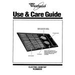
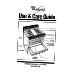
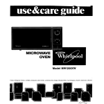
Estufa de Piso a Gas No. Parte W10161000 Rev. A STM02175 Rev. A. MF5555B Cover the following model: This guide contains useful information, read it carefully. Este manual contiene información útil, léalo detenidamente antes de poner a funcionar su estufa. Ampara el siguiente Modelo: MF5555B STM02175 Rev. A. No. Parte W10161000 Rev. A Freestanding Gas Range ¡ Felicidades por la compra de su nueva estufa ! MANUFACTURED BY: INDUSTRIAS ACROS WHIRLPOOL, S,A, DE C.V. Unidad Celaya km 280 CARRETERA PANAMERICANA C.P. 38020, CELAYA, GTO. Tel. 01(461)6185500 Le sugerimos que antes de usar su estufa lea cuidadosamente las instrucciones de este Manual. Consérvelo ya que la información contenida en el mismo será importante para el buen funcionamiento de su estufa durante muchos años. Partes y Características 2 with Pilot MF5555 Cercha 4 Cast Iron 2 Cercha 4 Fundición 2 MF5555 4 3 Installation 2 Parts and Features Index ¡ Congratulations ! 2 Gas Supply Connection FABRICADO POR: INDUSTRIAS ACROS WHIRLPOOL, S,A, DE C.V. Unidad Celaya km 280 CARRETERA PANAMERICANA C.P. 38020, CELAYA, GTO. Tel. 01(461)6185500 This range was carefully manufactured with the latest technical expertise. By purchasing it, you have received quality. Instale su estufa en un lugar protegido de las inclemencias del tiempo y sobre una superficie plana y resistente para soportar su peso. No permita que la usen niños o personas que no conozcan su funcionamiento. Proporciónele el mantenimiento adecuado. Utilice la estufa sólo en labores del hogar. No es un aparato de uso comercial. 5 1,0 A Max. How to Use Your Range 50/60 Hz 9 ± 10% 11 Características eléctricas nominales: 127 V Cleaning and Maintenance Panorámica Warranty 2 con Piloto Before you use your range, read the instructions in this manual. The information is important for best results in the use of your range. PARTES Y CARACTERÍSTICAS Capelo de Cristal Comal de Aluminio Parrillas Superiores Quemadores Estándar de Aluminio Tapas de Quemadores Super Quemador de Aluminio Encendido Electrónico Interruptor de Luz de Horno Parrila de Horno Termostato de Horno Asador Puerta Horno 11 12 12 11 Centros de Servicio Autorizados Format Filed for Distribuitor Formato llenado por Distribuidor Authorized Service Centers 11 Parts and Features Limpieza Panoramic 5 9 PARTS AND FEATURES Glass Lid Aluminum Griddle Upper Grates Aluminum Standard Burners Burner Caps Aluminum Super Burner Electronic Ignition Oven light button Oven Rack Oven Thermostat Broiler Oven Door Funcionamiento Acaba de adquirir un producto desarrollado con las más avanzadas técnicas de diseño y fabricación. 1,0 A Max. 4 50/60 Hz 3 Conexión ± 10% Instalación Electric Characteristics: 127 V 2 Install your range in an area that is protected against weather exposure, on a level floor strong enough to sustain its weight. Do not allow range to be used by children or unqualified adults. Provide for adequate maintenance. Use the range only in home applications. It is not designed for commercial use. Partes y Características Póliza de Garantía 2 Índice 3 ! ADVERTENCIA Peligro de Incendio y/o Quemaduras No permita que los niños usen o jueguen con la estufa; manténgalos alejados mientras está en uso. Mantenga los alrededores del aparato libres de materiales combustibles, gasolina y otros vapores o líquidos flamables. No se acerque demasiado a las flamas de los quemadores, ni use ropa suelta, ya que se puede encender y causar quemaduras. No use su estufa para calentar habitaciones, ya que esto es peligroso. Do not use extension cords or multiple outlets. No seguir estas instrucciones puede ocasionar incendio, quemaduras o la muerte. If your range has a power cord, it must be installed near an electrical wall outlet. Instalación If you will install an exhaust device, put it at 61 cm minimum from the range cooktop. 61 cm min. Do not install cabinetry directly above the range. Select the best location in your kitchen for your range, protected from wind and with enough space to open the oven door. EXHAUST DEVICE La instalación apropiada es su responsabilidad. Un técnico calificado o un técnico de Servicio debe instalar esta estufa. Remove all packing material and put the range accessories in their places. Proper installation is your responsibility. A qualified technician or Service technician must install this range. CAMPANA EXTRACTORA Retire los elementos de empaque y coloque los accesorios de la estufa. Seleccione la mejor ubicación para su estufa, no debe quedar expuesta a corrientes de aire y debe tener espacio suficiente para abrir la puerta del horno. 61 cm mínimo No instale gabinetes o muebles de cocina encima de la estufa. Si instala campana extractora, colóquela a 61 cm como mínimo, de la cubierta de la estufa. Installation Si su estufa cuenta con accesorios eléctricos, colóquela cerca de un tomacorriente de pared. No use extensiones eléctricas o contactos múltiples. Fire or Explosion Hazard Do not allow children to use or play with the range; keep children away while range is in use. Keep the range surroundings free of flammable material, gasoline and other vapors or flammable liquids. Do not get too close to the flame produced by the burners or wear loose clothing; your clothes may ignite if contact by open flames. Do not use your range to warm rooms, because this is dangerous. Failure to do so can result in death, fire or explosion. 3 ! WARNING 4 Conexión This kit is available at your nearest Authorized Service Center. Natural to LP NOTE: To operate this range with natural gas, is required a kit according to the chart: LP GAS OPERATING PRESSURE 11 in WATER COLUMN (6,36 oz/squared inch) BURNER UPPER STD UPPER SUPER OVEN BTU/h 6 700 7 100 13 000 THERMAL CAPACITY ORIFICE DIAMETER ORIFICE BTU/h 6 700 7 100 13 000 INCHES 0,029 0,030 0,042 NUMBER 74 78 57 THERMAL CAPACITY ORIFICE DIAMETER ORIFICE NOTA: El material mostrado para instalacion no viene con la estufa. INCHES 0,041 0,045 0,063 Cople-Niple de 9,5 mm (3/8"NPT) NUMBER 105 115 52 Llave de paso de 9,5 mm (3/8") NATURAL GAS OPERATING PRESSURE 7 in WATER COLUMN (4,04 oz/squared inch) BURNER UPPER STD UPPER SUPER OVEN Regulador de gas I M P O R TA N T LP to Gas Natural Tubo de cobre con tuercas cónicas de 9,5 mm (3/8") de longitud necesaria para llegar al gas This range is adjusted at the factory for use with L.P. gas. Model W10162151 Cople-Niple de 9,5 mm (3/8"NPT) a 9,5 mm(3/8")cónica Tubo de cobre con tuercas cónicas de 9,5 mm (3/8") W10162150 Tubo de Alimentación integrado a la estufa WF5555 1 Para conectar su estufa, utilice el material especificado en la figura de abajo. To use this range with natural gas, you must replace the surface and oven burner orifices, call your Whirlpool Service, the phone number is shown in the page 12. The technician must make sure that the connections have no leaks and the gas pressure in the range is the same as shown in the charts. CONEXIÓN DE LA ESTUFA A LA LÍNEA DE GAS NOTA: Su estufa puede estar equipada de fábrica con: 1.- Tubo de Alimentacion ó 2.- Válvula de Corte de Gas. Con el fin de facilitar el movimiento del aparato, el instalador debe hacer una espiral con el tubo flexible de cobre e instalar una llave de paso en la línea de suministro de gas, esta llave debe estar fuera de la estufa y accesible a las personas que la usan. W10162151 Este juego está disponible con su Centro de Servicio Autorizado. 4 Gas Supply Connection W10162150 Natural a LP GAS SUPPLY CONNECTION WF5555 LP a Gas Natural To connect the range, use the material shown in the bottom figure. Modelo 1 NOTA: Para operar esta estufa con gas natural, se requiere el juego de conversión de acuerdo con la siguiente tabla: 3/8" NPT to 3/8" brass pipe fitting Hex. adapter kJ/h 7 000 7 500 13 600 Gas Inlet Tube Fitting integrated to the range mm 1,05 1,15 1,613 Gas regulator CAPACIDAD TERMICA 3/8" copper pipe with 5/8" flared type nut. Necessary length to reach the gas ESPREA 105 115 52 DIAM. ESPREA 3/8" copper pipe with 5/8" flared type nut QUEMADOR SUPERIOR STD. SUPERIOR SUPER HORNO kJ/h 7 000 7 500 13 600 3/8" shut off valve GAS NATURAL PRESIÓN DE OPERACIÓN 1,76 kPa (18 cm Col. agua) mm 0,74 0,78 1,092 3/8" brass pipe fitting Hex. adapter Para usarse con gas natural ( de tubería) debe llamar a Whirlpool Service , para cambiar las espreas y hacer los ajustes necesarios, el número telefónico aparece en la página 12. El técnico calificado debe cerciorarse que la conexión no tiene fugas y que la presión de gas en la estufa es la que aparece en las tablas. ESPREA 74 78 57 CAPACIDAD TERMICA NOTE: The material shown for installation is not provided with the range. Esta estufa está preparada para funcionar con gas L.P. de tanque móvil o estacionario. QUEMADOR SUPERIOR STD. SUPERIOR SUPER HORNO NOTE: The range could be equipped from the factory with one of the following accesories: 1.- Gas Inlet Tube Fitting or 2.- Shut Off Gas Valve. IMPORTANTE DIAM. ESPREA Check with soap solution for leaks. GAS LP PRESIÓN DE OPERACIÓN 2,75 kPa (28 cm Col. agua) 2 To make it easier to move the appliance, the installer should loop the 3/8" copper tubing as shown in the illustration. Si la instalación no es nueva, limpie los tubos de cobre, para evitar que se tapen las espreas y/o pilotos. If the installation is not new, you should clean it in order to avoid the obstruction of orifices and/or pilots. 2 Cheque con agua jabonosa que no existan fugas. Funcionamiento 5 Knob on the mark of ignition. MED NOTA: No obstruya la salida de los gases de combustión de horno y asador. AJUSTE DE FLAMAS Si el quemador del horno presenta puntas amarillas en las flamas: Ajuste del aire del quemador del horno: 1.- Light a match and place it close the burner while you push and turn the knob 1/4 of the way,the burner will light immediatly. . MAXIMUM FLAME MINIMUM FLAME HI To turn on the surface burners manually: LO OFF HOW TO TURN ON THE BURNERS MANUALLY NOTE: In the case on power cut, your range can be ignited manually. 1 Retire la parrilla del horno (Ver Pág. 7) 2 Retire la charola del horno. (Ver Pág. 10) NOTA: Las diferentes altitudes sobre el nivel del mar y las variaciones en el suministro de gas, hacen necesario regular la entrada de aire primario a los quemadores para obtener una adecuada mezcla de aire-gas y así tener un buen funcionamiento de la estufa. 3 A - Afloje el tornillo del regulador. B - Gire el regulador un poco. C - Encienda el horno. D - Verifique que las flamas sean azules. E - Si las flamas no son azules repita desde el paso B. Al finalizar apriete nuevamente el tornillo. F - Coloque la charola del horno y la parrilla nuevamente en su lugar. ENCENDIDO ELECTRÓNICO DE QUEMADORES SUPERIORES Para encender los quemadores superiores con encendido electrónico independiente : APAGADO OFF Knob in ignition position. ELECTRONIC IGNITION BUTTON Some models (see page 2) have electronic ignition, to operate it push the button located on the left side of the manifold panel while you push and turn the desired knob. Release the ignition button when the burner lights. MED MINIMUM FLAME MAXIMUM FLAME HI LO OFF To turn on the surface burners with electronic ignition: TOP BURNERS WITH ELECTRONIC IGNITION NOTE: Because of different altitudes above sea level and variations in the supply of gas, you may need to adjust the main air intake to the burners. This will result in a better air-gas mixture and thus a better operation. 1 Remove the oven rack. (See page 7). 2 Remove the oven tray. (See page 10). 3 A - Locate the screw on the air shutter and loosen it. B - Turn around the air shutter. C - Turn on the oven. D - Verify that the flames are blue. E - If the flames are not blue, repeat since step B, when the flames are adjusted, tighten the screw again. F - Replace the oven tray and the oven rack. Algunos modelos (ver Pag. 2) cuentan con encendido electrónico, para operarlo oprima el botón que se localiza en el lado izquierdo del frente de perillas y al mismo tiempo presione y gire 1/4 de vuelta la perilla del quemador que desea encender. FLAMA HI MÁXIMA BOTÓN DE ENC. ELECTRÓNICO LO FLAMA MÍNIMA MED Perilla en posición de encendido. NOTA: En caso de no contar con electricidad, su estufa puede ser encendida manualmente. ENCENDIDO MANUAL DE QUEMADORES SUPERIORES Para encender los quemadores superiores: Acerque un cerillo encendido al quemador y al mismo tiempo presione y gire 1/4 de vuelta la perilla del quemador correspondiente. FLAMA HI MÁXIMA LO FLAMA MÍNIMA If the oven burner has yellow flames, it may require adjustment to the air shutters: How to adjust the oven burner air shutter: HOW TO ADJUST THE FLAMES NOTE: Do not obstruct the gas exhaust of the oven or broiler. MED Perilla en posición de encendido. 5 How to Use Your Range HORNO CON TERMOSTATO Y PILOTO DE ENCENDIDO 6 Algunos modelos (ver Pag. 2) cuentan con termostato y piloto de encendido en el horno, para operarlo: Knob position to use the broiler. 255 STM02174 Rev. A GUIA 160 STM02174 Rev. A 255 240 BROILER PAN HOLD Perilla en posición de encendido. GUIDES 230 TORNILLO DE AJUSTE DE PILOTO HORNO BROILER PAN 1.- Con el frente de perillas retirado, localice el tornillo de ajuste de la flama del piloto, en el termostato. (Ver figura). 2.- Retire la charola del horno (ver Pag. 10 ), gire el control aproximadamente 30° hasta sentir un tope, (esta es la posición de piloto) y encienda el piloto con un cerillo. BROILER Posición de Piloto. 4.- Replace the manifold panel, screws and knobs. 3.- Con un desarmador plano y delgado gire el tornillo de ajuste del piloto hasta obtener una flama de aproximadamente 1 cm. 3.- With a flat and thin screwdriver turn the adjustment screw until you get a flame approximately 3/8" tall. 4.- Coloque el frente de perillas, los tornillos y las perillas nuevamente en su lugar. Pilot Position. 2.- Remove the oven tray (see page 10) and turn the knob approximately 30° until you feel a small stop, turn the oven pilot on with a match or a lighter. ASADOR CHAROLA ASADOR Algunos modelos (ver pag 2) cuentan con asador en la parte inferior de la estufa. Para que el asador funcione debe encender el quemador del horno como se indica en la pag. 6, la perilla debe estar en la posición que indica la figura. El Horno debe estar vacio.Cerciorese que la charola de asador este correctamente colocada sobre las guias, como se muestra en la figura. 1.- Without the manifold panel, locate the adjustment screw on the thermostat, see the illustration on the right side. ADJUSTABLE FLAT SCREW FOR THE OVEN PILOT Knob on the mark of ignition. 2.- Turn the oven knob 1/4 of the way to ignite the oven burner, this position is minimum flame. 160 240 255 STM02174 Rev. A GUIA ºC 140 ºC 140 STM02174 Rev. A 240 OVEN WITH THERMOSTAT AND PILOT Posición de la perilla para usar el asador. Some models (see page 2) have a thermostat and pilot to control the oven function. 230 OFF 200 pilot 255 180 How to light the oven burner with thermostat and pilot: 160 1.- Open the oven door, light a match and place the flame at the igniter hole in the front of the oven tray, push and turn the oven knob to the pilot position. Verify that the pilot has been ignited. 230 200 180 CHAROLA ASADOR 3.- Verify that the oven burner has been ignited. ORIFICIO To adjust the pilot: GUIA APAGADO 6 Some models (see page 2) have broiler the bottom of the range. To turn on the broiler you have to turn on the oven burner as is indicated on page 6, the knob should be in the posicion that the draw shows. The oven must be empty. Check the broiler pan if is well colocated over the guides as the ilustration shows. 200 OFF 180 Para ajustar el piloto: ºC 140 ºC 140 160 2.- Gire la perilla hasta 1/4 de vuelta para que encienda el quemador. 3.- Verifique que el quemador del horno se haya encendido. 240 OFF 230 APAGADO 200 piloto 180 1.- Encienda un cerillo y colóquelo cerca del agujero de la charola del horno, presione y gire la perilla del horno hasta la posición de piloto. Verifique que el piloto haya encendido. COMAL No use materiales abrasivos como fibras de plástico o metal , use agua jabonosa y esponja para limpiarlo pues pueden rayarlo. COMAL DE ALUMINIO ANTIADHERENTE 7 Some models have the light switch located on the left side of the manifold panel. Some models (see page 2 have an oven light. OVEN LIGHT NOTA: Use el comal de alumio con FLAMA BAJA. Para proteger el acabado es recomendable poner un poco de aceite o mantequilla antes de usarlo. Use utencilios de plástico preferentemente a fin de protegerlo de rayaduras. Use agua jabonosa y esponja para limpiarlo, materiales abrasivos como fibras de plástico o metal pueden rayarlo. care.Check the burner being off when the Lid is closed. Do not put hot utensils over the Glass Lid The glass lid is made of resistant tempered glass, it should be handled with care to avoid breaking the glass. Open or close the glass lid with Some models (see page 2) include a glass lid. PARRILLA DEL HORNO El horno tiene 4 diferentes soportes para la parrilla, la parrilla tiene un tope que evita que se salga completamente del horno, para cambiar la posición de la parrilla siga los pasos: Para instalarla en la estufa: Para retirarla de la estufa: 1.- Empuje la parrilla hasta el tope. 2.- Levante la parrilla de la parte 1.- Jale la parrilla hasta el tope. frontal. 2.- Levante la parrilla de la parte frontal. 3.- Empújela nuevamente para que 3.- Jale nuevamente para liberarla. llegue hasta el fondo del horno. Para hornear alimentos muy grandes puede usarse el soporte extra de la parte inferior. SOPORTE EXTRA CAPELO DE VIDRIO Algunos modelos (ver Pag. 2) cuentan con capelo de vidrio. CAPELO El capelo de vidrio templado aunque es resistente, debe manejarse con cuidado para evitar que se rompa. Abra o cierre el capelo sin golpearlo. Asegúrese que los quemadores estén apagados cuando cierre el capelo y nunca encienda los quemadores cuando el capelo se encuentre cerrado.No coloque trastes calientes sobre el capelo. LUZ DE HORNO Algunos modelos (ver Pag. 2), cuentan con luz en el horno, la iluminación es importante para revisar el horneado sin abrir la puerta. Algunos modelos tienen el interruptor en el lado izquierdo del frente de perillas. 7 GLASS LID GLASS LID An extra rack position is provided for special cooking operations other than baking, such as roasting, where a large roasting container will require more heat and therefore need to be closer to the heat source or oven bottom. 1.- Push the oven rack until it stops. 2.- Lift the front part. 3.- Push it again until it stops. 1.- Pull the oven rack until it stops. 2.- Lift the front part. 3.- Pull it again until it is released. To install the oven rack: To remove the oven rack: EXTRA RACK POSITION The oven has 4 different supports for the oven rack, this rack has a stop to avoid droping from the oven, to change the rack position follow the steps: OVEN RACK Use plastic utensils to protect the griddle against scratches. Do not use abrasive materials like steelm or plastic fibres to clean it. use only cloth or spoonge, soap or detergent and rinse with water. Apply some butter before use the griddle to protect the finish. NOTE: Use the griddle with MINIMUM FLAME. Some models (see page 2) have aluminium griddle with antiadherent finish,to use it remove a top grate and put the griddle. ANTIADHERENT ALUMINIUM GRIDDLE Do not use abrasive materials, steel or plastic fibres to clean it. Use only cloth or sponge, soap or detergent and rinse with water. GRIDDLE Para reemplazar el foco del horno: 8 1.- Desconecte el cable tomacorriente de la estufa. 2.- Retire el foco y reemplácelo con un foco nuevo de 40 watts especial para aparatos domésticos. 3.- Conecte la estufa nuevamente. IMPORTANT: Do not obstruct the flow of combustion and ventilation air around the burner grate edges. Burner cap: Always keep the burner cap in place when using a surface burner. A clean burner cap will help avoid poor ignition and uneven flames. Always clean the burner cap after a spillover and routinely remove and clean the caps according to the General cleaning section. Gas tube opening: Gas must flow freely throughout the gas tube opening for the burner to light properly. Keep this area free of soil and do not allow spills, food, cleaning agents or any other material to enter the gas tube opening. Protect it from spillovers by always using a burner cap. QUEMADORES EXTERIORES E A. Burner cap B. Alignment pins C. Igniter D. Burner E. Gas tube opening. F. Orifice Diameter (see table of orifice diameter for gas type) NOTA: El cable tomacorriente debe conectarse a una toma de corriente con un voltaje de 127 V ± 10%. Cerciórese de que la instalación esté apropiadamente aterrizada. A F C B D D B EXTERIORS BURNERS NOTE: Connect the range in a wall outlet with a voltage of 127 V ± 10%. Be sure the installation is properly grounded. 1.- Disconnect the power cord. 2.- Remove the bulb and replace with a new 40 watts special appliance bulb. 3.- Connect the power cord again. How to replace the oven bulb: 8 F IMPORTANTE: No obstruya el flujo de aire de ventilación y combustión alrededor de los bordes de la parrilla del quemador. Tapa del quemador: Mantenga siempre la tapa del quemador en su lugar cuando use un quemador exterior. Una tapa de quemador limpia ayudará a prevenir un encendido inadecuado y una llama desigual. Limpie siempre la tapa del quemador después de un derrama y como rutina quite las tapas y límpielas de acuerdo con la sección Limpieza general. Abertura del tubo de gas: El gas debe fluir con libertad através de la abertura del tubo de gas para que el quemador se encienda adecuadamente. Mantenga esta área libre de suciedad y no permita que derrames, alimentos, productos de limpieza o cualquier otro material se introduzca en la abertura del tubo de gas. Use siempre la tapa del quemador para protegerla de derrames. A E C A. Tapa del quemador B. Espigas de alineación C. Encendedor D. Quemador E. Abertura del tubo de gas. F. Esprea (ver tabla de esprea para tipo de gas) A 9 6. Replace surface burner grates. 7. Turn on the burner. If the burner does not light, check cap alignment. If the burner still does not light, do not service the sealed burner yourself. Contact a trained repair specialist. B A. 1-1 1/2 (25mm-38mm) B. Orificios del quemador A. Incorrect. B. Correct. Orificios del quemador: Verifique de vez en cuando que las llamas del quemador sean del tamaño y forma apropiada tal como se ilustra arriba. Una buena llama es de color azul, no amarillo. Mantenga esta área libre de suciedad y no permita que los derrames, alimentos, productos de limpieza o cualquier otro material se introduzca en los orificios del quemador. B Para limpiar: IMPORTANTE Antes de limpiar, asegúrese de que todos los controles estén apagados y que el horno y la superficie de cocción estén fríos. No use productos comerciales para limpiar hornos, blanqueadores o disolventes de óxido. A 5. Replace the correct size burner cap onto the correct size burner base, making sure the alignment pins are properly aligned with the burner cap. 1. 2. 3. 4. Quite las parrillas del quemador exterior. Quite la tapa del quemador de la base del mismo y limpie de acuerdo con la sección limpieza general. Limpie la abertura del tubo de gas con un paño húmedo. Limpie los orificios obstruidos del quemador con un alfiler recto tal como se ilustra. No agrande ni distorsione el orificio. No use palillos de dientes de madera. Si el quemador necesita ser regulado, llame a un técnico competente para darle servicio. 3. 4. 1. 2. 5. Vuelva a colocar la tapa del quemador sobre la base del mismo, asegurandose de que las espigas de alineamiento estén debidamente alineadas con la tapa del quemador. A Remove the racks to the exterior burner. Remove the burner cap from the burner base and clean according to General Cleaning section. Clean the gas tube opening with a damp cloth. Clean clogged burner ports with a straight pin as shown. Do not enlarge or distort the port. Do not use a wooden toothpick. If the burner needs to be adjusted, contact a trained repair specialist. IMPORTANT: Before cleaning, make sure all controls are off and the oven and cooktop are cool. Do not use oven cleaners, bleach or rust removers. To Clean: Burner ports: Check burner flames occasionally for proper size and shape as shown above. A good flame is blue in color, not yellow. Keep this area free of soil and do not allow spills, food, cleaning agents or any other material to enter the burner ports. B A. Incorrecto. B. Correcto B A. 1-1 1/2 (25mm-38mm) B. Burner ports 6. Vuelva a colocar las parrillas del quemador exterior en su lugar. 7. Encienda el quemador. Si el quemador no se enciende, verifique el alineamiento de la tapa. Si el quemador todavia no se enciende, no intente reparar el quemador por su cuenta. Pongase en contacto con un técnico de reparación competente. 9 A 10 Limpieza tapar las ranuras de la misma. Como retirar la charola del horno: 1.- Tome la charola de las ranuras laterales y levántela de la parte trasera. 2.- Empuje la charola hacia adentro del horno para destrabarla. 3.- Jale la charola para sacarla. Electrical Diagram Range with Oven Light and Electronic Ignition with Independent Switch. Es necesaria la limpieza periódica de la estufa, use agua, jabón y un trapo húmedo, no use fibra metálica, porque se raya el esmalte. Limpie regularmente el hueco entre la cubierta superior y el frente de perillas. Su estufa cuenta con el Sistema de Autolimpieza en el horno (acabado rugoso), no es necesario que limpie las paredes, ya que con cada horneado se van quemando los residuos de alimentos que se van salpicando. Puede usarse papel aluminio para forrar la charola del horno, teniendo cuidado de NO IMPORTANTE Oven Bulb 40 W Desconecte la estufa de la corriente eléctrica antes de limpiarla o darle servicio. No utilice sosa cáustica o productos de limpieza que la contengan para limpiar la estufa. De no seguir esta instrucción se ocasionarán daños permanentes en las superficies donde se aplique. L1 Ignition Module. N Integrated Oven Light Switch & Electronic Ignition Switch DIAGRAMAS ELÉCTRICOS Interruptor Luz de Horno e Interruptor Módulo de Encendido Integrados ELECTRICAL DIAGRAMS N Módulo de Encendido 4, 6 u 8 salidas. L1 Disconnect from the elecrtical outlet before clean or service the range. Do not use caustic soda or cleaning agents which contain it to clean the range. Failure on following the above, will permanently damage the surfaces where it is applied. IMPORTANT Foco Horno 40 W Diagrama Eléctrico Estufa con Luz en el Horno y Encendido Electrónico con Interruptor Independiente. Regularly clean grates, burners, cooktop and the oven tray, use water, soap and a damp cloth, avoid using abrasive or sharp objects. Periodically clean the gap between the cooktop and the manifold panel. Your range has the Continuous Cleaning System in the oven, it is not necessary to clean the walls of the oven, the spills will burn each time you bake. You can use aluminum foil to wrap the oven tray, avoid covering the side grooves. How to remove the oven tray: 1.- Take the tray by the side holes and lift the rear side. 2.- Push the tray towards the top and back of the oven. 3.- Pull the tray out the oven. Cleaning and Maintenance 10 11 ! ADVERTENCIA Para su seguridad: No almacene gasolina u otros fluidos flamables en la cercanía de su aparato. Asegúrese que los muebles cercanos a su estufa, así como el muro y piso soporten una temperatura de 180oC, para que no sufran deformaciones. No obstruya las ranuras de la charola del horno. No seguir estas instrucciones puede ocasionar riesgo de fuego o explosión o la muerte. ! ADVERTENCIA Para su seguridad: Si huele a gas Abra las ventanas. No toque interruptores eléctricos. Apague todas las flamas cerrando la válvula general de paso. Llame inmediatamente a la central de fugas o a su proveedor de gas. N o s e g u i r e s ta s instrucciones puede ocasionar riesgo de fuego o explosión. 11 For your safety Do not store gasoline or other flamable liquids near to your range. Make sure that the furniture near to your range, as well as the wall and the floor must support a temperature of 180oC to avoid any deformation. Do not obstruct the side grooves in the oven tray. Failure to follow the above precautions may result in death, fire or explosion. ! WARNING For your safety IF YOU SMELL GAS: Open the windows. Do not activate any light switch. Close the gas line supply and the connection shut off valve. Immediately call your authorized repair service or your gas supplier. Failure to follow the above precautions may result in fire or explosion. ! WARNING When the final customer considers one of the events protected by this contract has happened, he/she will have to make contact with Whirlpool Service through our Call Center, in Monterrey, N.L and its surrounding area to (81) 83-29-2100; or from the interior of the Mexican Republic to 01-800-8-300-400:where a specialized service agent will take care of the matter. Our facilities are located in Miguel Alemán Highway km 16 Col. El Milagro C.P 66600. Apodaca, N.L. where Whirlpool original parts and accessories can also be found. For additional information of our services, visit www.whirlpoolservice.com.mx. PROCEDURE TO MAKE A WARRANTY EFFECTIVE: - When the range is used in other than normal, single family household use. - When the range is not used according to the use and care guide attached. - When the range has been repaired by unauthorized service. NOT COVERED CONCEPTS: Manufacturing defects that hinder total or partially the correct performance of the appliance. Repair, change of pieces and components. Handwork and transportation expenses derived from the fulfillment of the warranty, within our service net. The previous points will be made without any cost for the consumer. COVERED CONCEPTS: WHIRLPOOL MEXICO, S.A. DE C.V. Antigua Carretera a Roma km 9, Col. Milagro, Apodaca, N.L., Mexico, C.P. 66600, phone (81)83-29-21-00, in the terms of this policy, we warranty to the buyer and the consumer of this range identified in this following policy: WARRANTY 12 Teléfono 01-800-83-004-00 TERMS: REPRESENTANTE AUTORIZADO (Señale con precisión calle, número exterior o interior; colonia, ciudad, estado y C.P.) This warranty covers ONE YEAR beginning the day the buyer or consumer receives the range to his satisfaction. FIRMA DEL DISTRIBUIDOR Y SELLO WHIRLPOOL SERVICE Dentro de la República Mexicana Utilice sin cargo para usted el Servicio Nacional Clientes IMPORTANT NOTE NUM. DE SERIE ________________FECHA DE ENTREGA_______________ IDENTIFICATION FORMAT PRODUCTO______________ MARCA_________ MODELO_____________ El consumidor podrá solicitar que se haga efectiva la garantía que ampara esta póliza, ante la casa comercial donde se adquirió el producto. En caso de extravío de la póliza mencionada, el proveedor expedirá una nueva póliza de garantía, previa presentación de la nota de compra o factura respectiva. CONSUMER NAME _____________________________________________ DOMICILIO __________________________ TEL. ______________________ EL COMPRADOR DEBERÁ MANTENER ESTE DOCUMENTO EN SU PODER Y EN UN LUGAR SEGURO. This document must be shown in any transaction related with this warranty for products acquired in the Mexican Republic. If you bought your range out of the Mexican Republic, ask your authorized dealer to make valid your warranty. NOMBRE DEL DISTRIBUIDOR _____________________________________ ADDRESS________________________ PHONE ______________________ DOMICILIO_________________________ TEL. ______________________ DEALER NAME__________________________________________________ NOMBRE DEL COMPRADOR ______________________________________ NOTA IMPORTANTE Este documento deberá ser presentado para cualquier trámite relacionado con la garantía de productos adquiridos dentro de la República Mexicana, si usted compró su producto en otro país, acuda a la casa comercial/ distribuidor donde fué adquirido. THE CONSUMER CAN REQUEST THE WARRANTY COVERED BY THIS POLICY FROM THE DEALER WHERE THE PRODUCT WAS PURCHASED. FORMATO DE IDENTIFICACIÓN ADDRESS _______________________ PHONE ______________________ Esta garantía tiene una vigencia de UN AÑO a partir de la fecha en que el consumidor reciba de conformidad la estufa. PRODUCT___________TRADEMARK______________ MODEL __________ TÉRMINO: In case of loss of policy, the dealer will issue a new one, with the proper bill of sale or invoice. Al considerar el comprador final que ha ocurrido algún evento amparado por esta póliza, deberá ponerse en contacto con Whirlpool Service a nuestro Centro Nacional de Llamadas, desde Monterrey N.L y su área conurbada al (81) 83-29-2100 y desde el interior de la República Mexicana al 01-800-8-300-400; donde un asesor de servicio especializado lo atenderá. Nuestras instalaciones están ubicadas en Carretera Miguel Alemán Km. 16 Col. El Milagro C.P 66600. Apodaca, N.L. En donde también podrá encontrar accesorios y partes originales. Para mayor información de nuestros servicios, visite www.whirlpoolservice.com.mx." SERIAL NUMBER ________________DELIVERY DATE__________________ PROCEDIMIENTO PARA HACER EFECTIVA LA GARANTIA AUTHORIZED REPRESENTATIVE - Cuando el producto ha sido utilizado en condiciones distintas a las normales (la estufa no es para uso comercial o industrial). - Cuando el producto no ha sido operado de acuerdo con el instructivo de instalación y uso de la estufa. - Cuando el producto ha sido alterado o reparado por personas o establecimientos no autorizados por Whirlpool Service. DEALER SIGNATURE AND STAMP CONCEPTOS NO CUBIERTOS POR LA GARANTÍA: WHIRLPOOL SERVICE Call free in Mexico Use without charge the Nationwide Consumer Assistance Center Phone number 01-800-83-004-00 Defectos de fabricación que impidan total o parcialmente el correcto funcionamiento de la estufa, que se presenten dentro del término de vigencia de esta garantía. Reparación, cambio de piezas y componentes. Mano de obra y gastos de transportación derivados del cumplimiento de la garantía, dentro de nuestra red de servicio. Los puntos anteriores se harán sin costo alguno para el Consumidor. (Indicate precise steet, col. state and zip code). WHIRLPOOL MEXICO, S.A. DE C.V. Antigua Carretera a Roma km 9, Col. Milagro, Apodaca, N.L., México, C.P. 66600, Tel. (81)83-2921-00, en los términos de esta póliza, garantiza al comprador de la estufa identificada en la presente póliza, exclusivamente lo siguiente: CONCEPTOS CUBIERTOS POR LA GARANTÍA: 12 PÓLIZA DE GARANTÍA 13 13 14 14