1
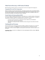
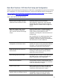
Troubleshooting the Dell PowerVault MD-Series iSCSI Storage Array Configuring the iSCSI Host Ports THIS WHITE PAPER IS FOR INFORMATIONAL PURPOSES ONLY, AND MAY CONTAIN TYPOGRAPHICAL ERRORS AND TECHNICAL INACCURACIES. THE CONTENT IS PROVIDED AS IS, WITHOUT EXPRESS OR IMPLIED WARRANTIES OF ANY KIND. © 2012 Dell Inc. All rights reserved. Reproduction of this material in any manner whatsoever without the express written permission of Dell Inc. is strictly forbidden. For more information, contact Dell. Dell, the DELL logo, and the DELL badge, PowerVault are trademarks of Dell Inc. Other trademarks and trade names may be used in this document to refer to either the entities claiming the marks and names or their products. Dell Inc. disclaims any proprietary interest in trademarks and trade names other than its own. June 2012 2 Contents About this Document ..................................................................................................... 4 iSCSI Communication Between the Storage Array and Host Server ............................................... 5 How are iSCSI Sessions Established? ................................................................................. 5 Enabling IPv4 or IPv6 ................................................................................................... 5 Should I Set Up iSCSI Sessions Automatically or Manually? ...................................................... 5 Setting Up iSCSI Automatically: Using the Dell MD Configuration Utility ..................................... 5 Setting Up iSCSI Manually: Using the MD Storage Manager ...................................................... 6 Troubleshooting the iSCSI Host Ports ............................................................................... 9 Default IP Addresses (iSCSI Host and Management Ports) ....................................................... 9 Recognizing Issues Involving the iSCSI Host Port ................................................................ 10 Basics: Cabling, Power and Network Switches .................................................................. 10 Troubleshooting Physical Connectivity Problems ............................................................... 12 Troubleshooting iSCSI Host Port IP Addressing and Configuration ........................................... 15 Other Device Discovery or iSCSI Session Problems ............................................................. 18 Using Mixed IPv4 and IPv6 Configurations ..................................................................... 18 Virtual Disk Not On Preferred Path (VNOP) ................................................................... 18 Verifying Device Discovery....................................................................................... 18 Basic Best Practices: iSCSI Host Port Setup and Configuration .................................................. 19 3 About this Document To understand the scope and organization of this document, refer to the following table. Topic What does this document contain? Description What is the intended audience? How is information categorized? Users experiencing problems setting up iSCSI communication between their storage array and host server Anyone wanting to know more about how the storage array establishes iSCSI sessions This document is divided into three broad sections: For more information An overview of the iSCSI data protocol between Dell PowerVault MD3200i-series and MD3600i-series storage arrays and host servers Recommended iSCSI host port setup guidelines Potential issues that occur when the storage array's iSCSI host ports are incorrectly configured, including steps on how to resolve A brief description of iSCSI host port setup and configuration best practices (including VMware-specific information) Other troubleshooting information relating to the MDseries iSCSI storage arrays Understanding and/or resolving physical connectivity issues between the iSCSI storage array and host server recognizing and resolving iSCSI host port configuration problems Solving common iSCSI device discovery errors See the following: MD-series user documentation at support.dell.com/manuals MD-series video series at www.del.ly/PowerVaultMD 4 iSCSI Communication Between the Storage Array and Host Server All MD-series iSCSI storage arrays have either two or four iSCSI host ports per RAID controller module (see Figures 4 and 5). These host ports are used to establish iSCSI sessions between the storage array and host server. To be able to write data to the storage array, the host server must be able to establish a successful iSCSI session with at least one port per RAID controller module. How are iSCSI Sessions Established? A basic overview of how an iSCSI session is set up between the iSCSI host ports on your storage array and the host server is below: Step 1: The iSCSI initiator on the host server sends a discovery session command to the storage array. Step 2: The MD storage array responds with a list of available iSCSI host ports. Step 3: Depending on how the iSCSI initiator is configured (the iSCSI initiator can be configured to connect to all storage array ports or a specific set of ports), the host server attempts to log in to available iSCSI ports on the storage array. Step 4: A successful log in by the host server to a storage array port establishes an iSCSI session. Enabling IPv4 or IPv6 IPv4 and IPv6 are both supported protocols on the MD-series iSCSI storage arrays. Whichever one you use, be aware of the following with either protocol: It is possible to enable both IPv6 and IPv4 on your host server. However, Dell recommends that you disable the one you are not using before setting up your storage array. Having both enabled may cause miscommunication between the storage array and host server. Make sure that the protocol you choose is enabled on both the storage array and host server. Mixing protocols (for example, enabling IPv4 on the storage array and IPv6 on the host server) will cause session interrupts and possible loss of data. Should I Set Up iSCSI Sessions Automatically or Manually? NOTE: In most cases, Dell recommends that you set up iSCSI communication between your host server and storage array automatically using the Dell MD Configuration Utility (MDCU) supplied on the installation DVD. However, since this document focuses mostly on troubleshooting problems that occur during iSCSI host port setup, the process of setting up iSCSI manually using MD Storage Manager is emphasized. For information on using MDCU, see the Help link in the utility itself. Setting Up iSCSI Automatically: Using the Dell MD Configuration Utility Using the Dell MD Configuration Utility is the easiest way to set up iSCSI communication between your storage array and host server. 5 You can start MDCU in any of the following ways: On Windows-based systems: - - During MD Storage Manager installation from the DVD shipped with your storage array, select the option to automatically start MDCU following reboot or Once you have installed the management software and utilities from the DVD, choose Start>Programs>Dell>MD Storage Software>Modular Disk Configuration Utility. On Linux-based systems: - Once you have installed the management software and utilities from the DVD, launch MDCU or Go to /opt/dell/mdstoragesoftware/mdconfigurationutility and run the executable Whichever way you launch MDCU, the window shown in Figure 1 is displayed. Figure 1. Dell MD Configuration Utility for iSCSI Setting Up iSCSI Manually: Using the MD Storage Manager To manually set up iSCSI communication between your host server and storage array, perform the following steps: Launch MD Storage Manager From the Setup tab, choose Manually Identify Host Using the MD Storage Manager wizard, enter the host and management information for each iSCSI host used. 6 Figure 2. MD Storage Manager Summary View 7 Figure 3. MD Storage Manager Physical View Once the storage array is successfully added to MD Storage Manager, all physical and logical components of your storage array are manageable using the menu-based interface. For more information on installing and using MD Storage Manager, see the Getting Started Guide that shipped with your storage array and the Help option from the main window. 8 Troubleshooting the iSCSI Host Ports There are two different RAID controller module host port layouts on the MD-series iSCSI storage arrays, depending on model type: Figure 4. Four-port MD3200i-series 1GB iSCSI storage array Figure 5. Two-port MD3600i-series 10Gb iSCSI storage array Default iSCSI Host and Management Port IP Addresses Each port on the storage array is assigned a default, factory-set IP address. However, in the case of the iSCSI host ports, these default addresses may not appear initially since DHCP is not enabled by default at the factory. Table 1. Default IP Addresses on MD-series storage array (all models) Port ID Controller 0 Controller 1 Subnet mask iSCSI port 0 192.168.130.101 192.168.130.102 255.255.255.0 iSCSI port 1 192.168.131.101 192.168.131.102 255.255.255.0 192.168.132.101 192.168.132.102 255.255.255.0 iSCSI port 2 * 9 iSCSI port 3 * Ethernet management port 192.168.133.101 192.168.133.102 255.255.255.0 192.168.128.101 192.168.128.102 255.255.255.0 * Port 2 and 3 are available on 1Gb iSCSI MD3200i-series storage arrays only Recognizing iSCSI Host Port Problems Problems occurring due to misconfigured or nonfunctional iSCSI host ports on your storage array's RAID controller modules can appear in a number of different ways. However, typical iSCSI host port issues may include: − − − − Status LEDs on iSCSI ports not lit or indicating fault (refer to Table 2 for LED values) Unable to ping an iSCSI port from the host server on the same subnet Dynamic Host Configuration Protocol (DHCP) is unable to assign an IP address for one or more of your RAID controller modules Duplicate IP addresses appear (either manually set or set incorrectly in factory) Basics: Cabling, Power and Network Switches Simple issues, such as an improperly seated iSCSI cable or a defective and/or powered-down hardware component, are often the root cause of a number of problems. If a physical link error occurs or you are unable to connect to a storage array in MD Storage Manager, it is always useful to perform a simple, standard troubleshooting protocol: 1. Verify you have a solid, well-seated connection between the RAID controller module's iSCSI host port(s) and your host server and/or network switch. 2. If you are using a network switch, verify the following: - - - - All active link and link status LEDs are lit (an unlit activity LED is not necessarily a problem) The Ethernet switch you are using matches the speed of your RAID controller module (for example, do not use a 1GB switch on a 10Gb iSCSI storage array) Do not connect an Ethernet switch with a speed of less than 1Gb to the storage array Your switch speed settings in MD Storage Manager match settings on your host server (see Using Ethernet Jumbo Frames) 3. Verify that MD-series storage array enclosures and RAID controller modules are powered on and show the proper LED status configurations. (See Table 2.) 4. Ensure that all cabling and connectors are functional. If uncertain, swap current cables with known good cables and determine whether the problem resolves. 10 Figure 6. Enclosure Status LEDs (Front) Table 2. Enclosure Status LED Values LED Enclosure status Function Solid blue: Normal operation Blinking blue: Solid amber: Blinking amber: Enclosure power Solid green: Host identifying Enclosure rebooting or being reset Enclosure fault or host not using preferred path to virtual disks At least one power supply active Figure 7. Enclosure/RAID Controller Module Status LEDs (Back) 11 Table 3. Enclosure/RAID Controller Status LED Values LED DC Power Function Solid green: Power supply/fan fault Off: DC output voltage not within limit Solid amber: DC output voltage not within limit or fan fault detected AC power Controller power Controller fault iSCSI port link DC output voltage within limit Off: Solid green: No fault condition AC input voltage within limit Off: Solid green: Off: Solid amber: Off: Solid green: No power or AC input voltage is not within limit Controller powered on Controller powered off Controller fault detected Controller operating normally 10Gbps Ethernet connection established Solid amber: 1Gbps Ethernet connection established iSCSI port activity Off: Solid green: No link No activity/connection. Blinking green: Management port speed Off: Solid green: Port active, connection No link 1Gbps Ethernet connection established Blinking amber: 100Mbps Ethernet connection established Off: Management port activity No link or 10Mbps connection established Solid green: Port active/connection Off: No activity 12 Troubleshooting Physical Connectivity Problems When experiencing problems with iSCSI host ports, always first check for simple connectivity issues (see Basic Cabling, Power and Switch Issues). If problems persist, refer to the following table: Table 4. Diagnosing iSCSI Host Port Connectivity Issue/Problem Recommendation Experiencing physical link errors or unable to successfully establish iSCSI sessions Verify that a supported cable is connected from the iSCSI host port(s) of the RAID controller module to either: (1) an industry-standard network switch or (2) directly to the iSCSI initiator on the host server Recommended Cable CAT 6A or better CAT 5E or better Maximum Speed 10Gbps (MD3600i-series) 1Gbps (MD3200i-series) Suspected bad cable Replace the suspected bad cable with a known good cable. If problems persist, cable is probably OK. No link LEDs visible on RAID controller (rear) If you are using a network switch, verify that it is powered on and Ethernet ports on both the network switch and RAID controller module are active. Also, make sure the storage array enclosure is powered on. NOTE: For any iSCSI host port shown in MDSM, verify its connection state as either Connected or Disconnected in the Configure iSCSI Host Ports window. Does the network switch and iSCSI host port speed match? Network switch and iSCSI host port speeds must match (or at least not exceed the capability of the switch). NOTE: iSCSI host ports can only auto-negotiate to port speeds set in MD Storage Manager. Additionally, the storage array will not downward autonegotiate (for example, will not automatically auto-negotiate a 10Gb port setting down to a 1Gb speed if a 1Gb switch is connected). Any down-speed link setting/component in a network configuration will impact throughout, regardless of the speed of other components. 13 Reduced throughput If you have connectivity but are experiencing reduced throughout, make sure your iSCSI port is not connecting to the host server through a slower-thanexpected speed. For example, a 10Gb port can connect using a 1Gb network switch, but the slower switch will impact throughput. 14 Troubleshooting iSCSI Host Port IP Addressing and Configuration If you experience problems setting up the iSCSI host port on your storage array, refer to the following table: Table 5. Diagnosing iSCSI Host Port Configuration Problems Issue/Problem Recommendation What are the iSCSI host port IP addresses? Default values for RAID controller module iSCSI host ports are determined by static addressing. On IPv4enabled configurations, default addresses are: Default iSCSI Host Port IP Addresses Controller 0 Controller 1 Subnet mask Port 0 192.168.130.101 192.168.130.102 255.255.255.0 Port 1 192.168.131.101 192.168.131.102 255.255.255.0 Port 2 * 192.168.132.101 192.168.132.102 255.255.255.0 Port 3 * 192.168.133.101 192.168.133.102 255.255.255.0 * Port 2 and 3 are avalable on 1Gb iSCSI MD3200i-series storage arrays only NOTES: - - - - IP addresses for the iSCSI host ports are visible in the MD Storage Manager Configure iSCSI Host Ports window, even if the ports are disconnected On IPv6-enabled configurations, iSCSI ports on the MD storage array will always be accessible using the IPv6 link local address determined from the MAC address of the port (unless IPv6 is disabled). Dell recommends that you do not configure more than one NIC per host on the same subnet. Multiple NICs on the same subnet can cause IP address confusion, especially in direct-attached configurations. Dell does not recommend using standard DHCP on the host server to connect to the iSCSI hosts ports. However, you can use static DHCP (or mapped DHCP) to make sure that the host server specifies the same IP address each time it attempts to establish an iSCSI session 15 Using more than one NIC on the same subnet Check that you can ping all iSCSI host ports from the attached host server. Multiple NICs configured on the same subnet cannot complete a ping command because the default NIC originating the ping command may not have a path to the target IP address being pinged. On Windows-based hosts, use the -S parameter to specify the source and target IP addresses on the RAID controller: ping 192.168.130.101 –S 192.168.130.102 On Linux-based hosts, use the -I parameter to specify the target IP address from the eth0 interface: ping –I eth0 192.168.130.101 NOTES: - - - Using Ethernet Jumbo frames (larger than 1500 bytes) You should be able to successfully ping multiple NICs on different subnets. However, if each NIC is on the same subnet, you must map each iSCSI port manually via the host server iSCSI initiator. Make sure Enable ICMP PING responses is selected in the MD Storage Manager Configure iSCSI Host Ports window Check your firewall settings to make sure that ICMP ping packets are not blocked internally If you are using Ethernet frames with a maximum transmission unit (MTU) of more than 1500 bytes, they are considered Jumbo frames. The MD-series storage array supports MTU sizes of up to 9000 bytes. However, you should tune your maximum MTU size based on the application and drivers used in your configuration. Smaller MTU sizes may yield better overall data throughput. 1. Verify that Jumbo frames are set to Enabled for all network components (switches, NICs and the storage array). 2. Ensure that the same MTU size is set on all components. If unequal sizes are set on host and target, the smallest setting will be used. The switch may fragment any frame that is larger than its set MTU size. 3. After setting the proper sizes, verify network 16 packet transmission. On Windows-based hosts, send a 9000-byte packet to 192.168.130.101 using the following command: ping –l 9000 192.168.130.101 On Linux-based hosts, use this command to perform the same function: ping –s 9000 192.168.130.101 If the ping is successful, the packet transmission has completed. If ping does not work, the packet was dropped. NOTE: Make sure that all components along the data path support the MTU size you are specifying. Using VLAN tagging Verify that the VLAN ID of the iSCSI host ports are set to the same values you are using for VLAN tagging. All tag values must be the same for the host server, switch and server array. 17 Other Device Discovery or iSCSI Session Problems Before starting the discovery process, verify that your host server can ping all iSCSI target ports. Using Mixed IPv4 and IPv6 Configurations When you initially set up your iSCSI storage array, the discovery process returns all accessible network portals on the storage array. If both IPv4 and IPv6 are enabled and there are multiple storage arrays on the same subnet, duplicate iSCSI sessions may be established. While both are supported, there is no performance advantage to having multiple sessions established. Virtual Disk Not On Preferred Path (VNOP) If an error message is displayed indicating that a virtual disk is not on a preferred path, verify that your iSCSI session topology is configured in accordance with all information in this document. To establish a virtual disk on a preferred path, the following minimal connectivity is required: - At least one active iSCSI session to each RAID controller module must be established. Each iSCSI session must have disk ownership. There must be a data path between the RAID controller owning the virtual disk and the host server(s). Verifying Device Discovery There are several ways to verify that you have successfully created an iSCSI session. First, check that your host server appears in the Mappings tab of MD Storage Manager Array Management Window. Second, right-click on a LUN and compare the information with that shown in the iSCSI initiator on the host sever. If necessary, define a new host in the Setup tab of the Array Management Window using the Manually Define Hosts option. 18 Basic Best Practices: iSCSI Host Port Setup and Configuration Tables 3 and 4 provide high-level descriptions of basic Dell-recommended best practices for iSCSI host port configuration. For a more detailed discussion, see the Dell IP SAN Best Practices whitepaper at http://www.dell.com/us/enterprise/p/d/campaigns/powervault-resources.aspx and the iSCSI Best Practices video at http://del.ly.PowerVaultMD. Table 6. Basic iSCSI Host Port Best Practices Best Practice Description Each iSCSI port on a RAID controller module should be a different subnet Separating subnets prevents accidental misconfiguration. Additionally, some operating systems (ESX and some Linux versions) require multiple subnets for different NICs on single host servers. When using Jumbo frames, enable them on all network components (NICs, network switches and storage arrays) If you use Jumbo frames, a common mistake is to enable them on only one network component. Jumbo frames must be enabled on each component, including NICs, network switches and storage arrays. Also, the MTU size of a Jumbo frame packet must be adjusted based on the requirements of the component. Verify MTU settings recommended by the manufacturer on each component. Always separate Ethernet management and iSCSI data traffic Management and data traffic on the same physical network will result in lower performance and data throughout. (See Recommended Management Configuration on MD-Series Storage Arrays.) Enable IEEE 802.3x flow control on iSCSI networks Always enable IEEE flow control (sending and receiving) on iSCSI initiators and any network switch that carries iSCSI traffic. Avoid routing (Layer 3) iSCSI data Avoiding the use of a router for iSCSI data reduces the number of hops, improves throughput and lessens complexity of the configuration. Disable Unicast broadcast If using network switches, always disable Storm control on switch switch ports that are connected to the iSCSI initiator(s) or targets. Enable PortFast mode Always enable PortFast mode for the spanning tree protocol (STP) on all network switch ports connected to iSCSI initiator(s) or targets. Always separate management and iSCSI network traffic on a different vSwitch Dell strongly recommends that you separate your management network from your iSCSI traffic network. Each should be on different virtual 19 switches with different subnet address, as well as physically separate network switches. Setting up management and iSCSI traffic on the same networks may result in network congestion and performance loss. ESX-based host servers will not fail back LUNs automatically when a VNOP error is encountered You must redistribute the virtual disks in MD Storage Manager Map each VMkernel port to only one active adapter By default, each VMkernel port on the vSwitch shows all network adapters as active. You must manually override this setting so that each port maps to only one corresponding active adapter. (For example, VMkernel port vmk1 should map to active adapter vmnic1, VMkernel port vmk2 should map to vmnic2, etc.) To perform this manual override: 1. Log in to the vSphere Client and select the host server. 2. From the Ports tab, select a VMkernel port and click Edit. 3. Click the NIC Teaming tab and select Override vSwitch failover order. 4. Designate only one adapter as active and move all remaining adapters to the Unused Adapters category. 5. Repeat steps 1 through 4 for each VMkernal port. 20