1
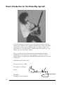
Owner’s Manual E 1 IMPORTANT SAFETY INSTRUCTIONS • • • • • • • • • • • • • • • • • • Read these instructions. Keep these instructions. Heed all warnings. Follow all instructions. Do not use this apparatus near water. Mains powered apparatus shall not be exposed to dripping or splashing and that no objects filled with liquids, such as vases, shall be placed on the apparatus. Clean only with dry cloth. Do not block any ventilation openings, install in accordance with the manufacturer's instructions. Do not install near any heat sources such as radiators, heat registers, stoves, or other apparatus (including amplifiers) that produce heat. Do not defeat the safety purpose of the polarized or groundingtype plug. A polarized plug has two blades with one wider than the other. A grounding type plug has two blades and a third grounding prong. The wide blade or the third prong are provided for your safety. If the provided plug does not fit into your outlet, consult an electrician for replacement of the obsolete outlet. (for U.S.A. and Canada) Protect the power cord from being walked on or pinched particularly at plugs, convenience receptacles, and the point where they exit from the apparatus. Only use attachments/accessories specified by the manufacturer. Unplug this apparatus during lightning storms or when unused for long periods of time. Turning off the power switch does not completely isolate this product from the power line so remove the plug from the socket if not using it for extended periods of time. Refer all servicing to qualified service personnel. Servicing is required when the apparatus has been damaged in any way, such as power-supply cord or plug is damaged, liquid has been spilled or objects have fallen into the apparatus, the apparatus has been exposed to rain or moisture, does not operate normally, or has been dropped. Do not install this equipment on the far position from wall outlet and/or convenience receptacle. Do not install this equipment in a confined space such as a box for the conveyance or similar unit. Use only with the cart, stand, tripod, bracket, or table specified by the manufacturer, or sold with the apparatus. When a cart is used, use caution when moving the cart/apparatus combination to avoid injury from tip-over. The lightning flash with arrowhead symbol within an equilateral triangle, is intended to alert the user to the presence of uninsulated "dangerous voltage" within the product's enclosure that may be of sufficient magnitude to constitute a risk of electric shock to persons. The exclamation point within an equilateral triangle is intended to alert the user to the presence of important operating and maintenance (servicing) instructions in the literature accompanying the product. CE mark for European Harmonized Standards CE mark which is attached to our company’s products of AC mains operated apparatus until December 31, 1996 means it conforms to EMC Directive (89/336/EEC) and CE mark Directive (93/68/EEC). And, CE mark which is attached after January 1, 1997 means it conforms to EMC Directive (89/336/EEC), CE mark Directive (93/ 68/EEC) and Low Voltage Directive (73/23/EEC). Also, CE mark which is attached to our company’s products of Battery operated apparatus means it conforms to EMC Directive (89/336/EEC) and CE mark Directive (93/68/EEC). FOREWORD I n the popular domain of “Classic Rock” Brian May needs no introduction. Thanks to his expansive body of work with Queen, he is quite literally a global institution. In addition to being one of the genre’s finest songwriters and arrangers, fans and critics alike consider him to be one of rock’s most distinctive and tasteful guitarists. And, just like his unique playing style, Brian’s instantly recognisable guitar tone is highly revered, fortifying his status as a living legend. As you know, throughout his lengthy and highly successful career Brian has always been associated with Vox amps and his celebrated wall of nine AC30 combos is a “Brian May trademark” that is instantly recognized in all four corners of the globe. As soon as said “wall” is spotted on a stage, the audience immediately knows who is going to be plugging into it! What isn’t as well known is the source of many of Brian’s most celebrated recorded tones. Believe it or not, many of them have been made using a tiny, homemade combo that was built for him by Queen’s bassist, John Deacon, back in the early ‘70s. Because of its maker’s name, this unique and wonderful sounding little device was christened the “Deacy” amp and, as just stated, its unique voice can be heard on some of Brian’s and Queen’s most famous recordings, including “The Fairy Feller’s Master-stroke” & “Bijou”, to name but two. By working extremely closely with Brian, we are proud to offer you this exciting new product — the Brian May Special... 1 Brian’s Introduction for Vox Brian May Special! © Richard Gray For years I have been wondering what on Earth I would do if the Legendary Deacy Amp one day stopped working! And so often I have been asked where such an amp could be bought, to produce sounds as far apart in time as “The Fairy Feller’s Masterstroke” from “Queen 2,” and “Bijou” from the “Innuendo” album. Well..... It’s here!! At last I am secure in the knowledge that Steve Grindrod &Vox now know how to provide me—and you—with an infinite supply of sounds that could NEVER be squeezed out of an Amp Simulator!!! THIS WILL DO IT FOR YOU!!! Or my name’s not .....BM! Plug right in and Enjoy! Cheers! Brian May Dec 2002, London, England. 2 DETAILS: History, Use and Design Philosophy. A s stated in the FOREWORD, the original Deacy amp was made by Queen’s bass player, John Deacon, sometime in 1970/1971, whilst he & Brian were studying at University. The compact combo he built boasts no controls what-so-ever and, according to legend, was put together from parts the bassist managed to salvage from a rubbish skip (a large garbage container)! The amplifier circuit-board* John used consisted of a simple, solid-state design that dates back to a Mullard circuit that was published when transistors first became popular and was almost definitely “rescued” from what was once a car radio. The resourceful Mr. Deacon mounted this amp board into a compact, 1960’s “bookshelf” HiFi speaker cabinet and used it to drive the small woofer and tweeter combination the cabinet contained. When connected to a 9 Volt battery the Deacy produced a massive 0.45 Watts of power...RMS of course! © Richard Gray *NOTE: for more technical details regarding the original Deacy please refer to the “Technical Talk” section at the end of this manual. The two friends quickly discovered that when the Deacy was coupled with Brian’s homemade Treble Booster pedal (which actually accentuates the upper-mid frequencies to be exact), and his world-famous, homemade “Red Special” guitar, the resulting tone was both extremely pleasing and unique. As a result of the great sound it produced this 100% homemade set-up was used to record a large amount of Brian’s lead and guitar orchestration work on Queen’s vast catalogue of hit albums and singles. Obviously the original Deacy is a very unique and, due to its age, irreplaceable amplifier. Not surprisingly, Brian treats it with due reverence, as it is part-and-parcel of his signature sound. Unfortunately, the electrical components it employs are long gone from production, as is the speaker system it uses and, for that matter, the batteries it requires are not readily available! Also, the original is extremely limited because it has no controls and is also never used purely by itself — Brian always uses it in conjunction with his homemade Treble Booster. Because of all these truths, after consulting with Mr. May, it was decided that the Brian May Special should be a variation of the original Deacy “system” (the Deacy amp plus his homemade Treble Booster) that, in addition to emulating its unique sound, offers a number of features and controls that the original doesn’t have. Brian was also very keen for the resulting product to be as affordable as it is practical, so that its sound could be brought to as wide an audience as possible. Hence the format of the VOX Brian May Special recording amp you’re now the proud owner of... 3 In a nutshell, the Brian May Special is a 10 Watt, 1 x 6.5" combo that sounds identical to Brian’s homemade “Deacy System” (i.e. his Treble Booster/Deacy amp combination) and also offers the following additional features that dramatically enhance its flexibility: Controls for Gain, Tone and Volume plus a High/Low Gain switch. A Booster Output that allows you to use the Booster section of the Deacy to drive another amp. This is a very useful facility as Brian uses his homemade Treble Booster to overdrive the AC30s he uses live and the Booster section of the Brian May Special sounds exactly the same as Brian’s homemade device. An Emulated Recording/Headphone jack. An External Speaker jack. IMPORTANT NOTE: In Brian May’s “Original Deacy System” both the Treble Booster and the Deacy amp are powered by 9 Volt batteries. Because of this the Brian May Special has two “battery simulation circuits” (one for the Booster section, one for the amp section) that emulate the unique characteristics of batteries. For more information on the combo’s features, read on.... 4 GUIDED TOUR OF THE BRIAN MAY SPECIAL’S TOP PANEL As you’re about to discover, this unique combo is a truly versatile piece of gear that’s ideal for practicing, recording, or hooking-up to your favorite amp for added gain and sustain. We’re sure it will provide you with a plethora of great additional guitar tones that feel as good as they sound. Let’s take a quick tour of the features and controls that make your new Brian May Special as flexible as it is toneful... The Top Panel 1 2 3 4 5 6 7 8 9 1. INPUT jack This is where you plug your guitar into the Brian May Special. Please use a high quality guitar cable. 2. GAIN control This adjusts the gain of the Brian May Special’s Booster section and, in so doing, affects the overall gain of the amplifier. Turning this control up (clockwise) will produce rich, overdriven tones that range from mildly crunchy to maximum saturation. Also, when this control is turned down to low settings, your sound will clean up nicely. This control is also extremely effective when you are using the BOOSTER OUTPUT (3) to drive the pre-amp of another amplifier. 3. BOOSTER OUTPUT jack This output allows you to use the Brian May Special’s Booster section to drive the pre-amp of another amplifier. Doing this will “push” the input of the amplifier you connect it to into a smooth, overdriven sound and will add sustain and musical harmonics. Remember, the BOOSTER section of the Brian May Special is an exact emulation of the homemade Treble Booster pedal Brian uses to drive the Normal channel of his AC30s whenever he is playing live or in the studio. 5 IMPORTANT NOTE 1: Using the BOOSTER OUTPUT disconnects the rest of the Brian May Special. So, when you use your Brian May Special as a BOOSTER you can’t use it as an amp as well. IMPORTANT NOTE 2: When using the BOOSTER OUTPUT, the only two controls that affect its output are the GAIN knob (2) and the GAIN switch (4). The TONE control (5) and VOLUME control (6) have no affect on the BOOSTER OUTPUT what-so-ever. BRIAN MAY SETTING TIP #1: For the BOOSTER to sound exactly like Brian’s homemade Treble Booster: — the GAIN control (3) needs to be set on full “10” & — the GAIN switch (4) needs to be in the HIGH “pushed in” position. 4. GAIN switch This push switch allows you to select between High and Low gain settings for the “pre-amp” section (see Flow Chart on page 11). The HIGH setting (switch “pushed in”) produces natural sounding, heavily overdriven sounds while the LOW setting (switch “popped up”) gives a smoother, mellower overdrive that’s ideally suited for more subtle, dynamic playing styles. Keep in mind that the effect of this switch will vary depending on how you have the GAIN control (2) set. As always, experimentation is the best way to achieve your desired sound. 5. TONE control This control has been placed after the overdrive circuitry of the Brian May Special and adjusts the overall tone of the amp. Turning it clockwise from “0” towards “+” adds in high frequencies and gives you a brighter sound, while turning it counter-clockwise from “0” to “-” adds in bass frequencies, resulting in a rounder, warmer sound. Setting this control in the middle (0) renders it inactive. As with the other controls, please experiment with this one to find the settings that best suit your playing needs. 6. VOLUME control This adjusts the overall volume of the combo. BRIAN MAY SETTING TIP #2: For the Brian May Special to sound exactly like Brian’s homemade Treble Booster/Deacy set-up, here are the settings: 6 — — GAIN control on full “10” GAIN switch in the HIGH “pushed in” position — TONE control in the center “0” — VOLUME control at “ ” 7. RECORDING/HEADPHONE jack This speaker-emulated jack enables you to connect directly to a mixing console or portable recorder such as a Korg PXR4 or D1600. Additionally, you can hookup headphones to this jack for a great emulated sound. Turning the VOLUME controls (6) to zero will facilitate “silent” practicing. 8. EXTENSION SPEAKER jack This jack allows you to connect an external speaker cabinet for added tonal possibilities. Be sure to use a speaker cable (unshielded) when doing this and that you’re using a cabinet that has an impedance not less than 8 Ohms and a Wattage rating of 10 Watts or more. IMPORTANT NOTE: Connecting an extension speaker here mutes the internal speaker. For optimum performance we strongly recommend the following: a) ONLY use an extension cabinet of 8 Ohms impedance or more with this amplifier NOTE:– using speakers with impedances of less than 8 Ohms can damage the amplifier! b) DO NOT use a speaker cabinet with a Wattage rating that is less than 10 Watts. If you ignore this warning, you could end up blowing a speaker — and that’s definitely not recommended! c) ALWAYS use a high quality speaker cable (unshielded) to connect an external cabinet — NEVER use a guitar (shielded) cable d) You must turn off the power before you connect the cable. The amp may be damaged if you connect or disconnect the cable while the power is on. 9. POWER switch This is where you turn on the power. Please be sure that all connections are made prior to turning this unit on. VERY IMPORTANT NOTE: Always make sure you turn on the Brian May Special before connecting the BOOSTER OUTPUT to another amplifier to avoid doing any damage to the front end of the amp you are connecting to. 7 Brian May Special Specifications • Dimensions (W x H x D): 13.3 x 11.8 x 6.9 (inches)/ 338 x 300 x 175 (mm) • Weight: 12 lbs. / 5.6 kg • Output Power: 10 Watts (RMS) • Speaker: 1 x 6.5" custom-voiced, full-range speaker • Inputs: Input jack • Outputs: Booster Output, External Speaker, and Recording/Headphone Line Out. • Controls: Gain, Tone and Volume. Gain (High/Low) push switch, Power switch (with LED) *Specifications are subject to change without notice. 8 Technical Talk 1) The Original Deacy As already mentioned in DETAILS at the beginning of this manual, the original amplifier itself dates back to a Mullard circuit that was published when transistors first became available as a consumer product, and was probably “rescued” from a car radio, as it is built on a commercial printed circuit board. The amp features the total amount of four germanium transistors — two for the preamp and driver stage, and two for the push-pull output stage. The circuit also has an inter-stage driver transformer (between the driver transistor and the pushpull pair) and also an output transformer from the output stage into the speaker. When connected to a 9 Volt lantern battery the amp produces a massive 0.45 Watts output. © Richard Gray The amp circuit-board was mounted into a 1960’s contemporary bookshelf HiFi speaker cabinet, of quite small proportions (England’s bookshelves were not very big at the time!), and contains a small woofer loudspeaker and a cone tweeter that is coupled through a capacitor. Due to the speaker technology of the time (and having been played for many years by Brian) it has a relatively mellow sound when compared to today’s hi-tech, hi-fidelity speaker systems. As it happens, said mellowness is actually quite complementary when the original Deacy is used in conjunction with Brian’s homemade guitar and Treble Booster. Due to the very low input impedance (12kOhms) of the amp John Deacon salvaged from a pile of rubbish (remember, in all probability it was originally designed for use in a car radio), it is actually not very useable when a guitar is plugged directly into it. This is because guitar pickups need to see a much higher impedance in order to do their job properly. Hence the use of Brian’s homemade Booster pedal was vitally important, not only in terms of tone but also in terms of the overall compatibility of the signal path. As also already stated, all the components used in the original Deacy, including speakers and the batteries used, are no longer in production. It is also worth reiterating two other facts: i) The original Deacy had no controls what-so-ever. & ii) It was always used in conjunction with Brian’s homemade Treble Booster — which, to be accurate, actually boosted the upper mid-range frequencies. 9 2) The new Brian May Special To recap on DETAILS, after many meetings with Brian it was decided that this model would satisfy the following three criteria: i) 10 It would sound and feel exactly like his homemade “Deacy system” which comprises of his Treble Booster and the original Deacy amp ii) built by John Deacon. It would also offer more power, features and tonal flexibility. & iii) It would be as affordable as possible. Brian May Special Signal Path Flowchart R S TREBLE GAIN T OUTPUT TRANSFORMER SIMULATION BOOSTER ONLY OUTPUT JACK TONE SPEAKER SYSTEM EMULATION T VOLUME R S HEADPHONE AND RECORDING OUTPUT BOOSTER S T PREAMP & DRIVER STAGE PUSH-PULL OUTPUT STAGE S 10 Watt POWER AMP GAIN SWITCH EXTERNAL LOUDSPEAKER OUTPUT INTERNAL LOUDSPEAKER (FULL RANGE RESPONSE) T 9V BATTERY SIMULATOR 9V BATTERY SIMULATOR With reference to the above flowchart: i) The TREBLE BOOSTER stage is a direct copy of Brian’s homemade Treble Booster pedal. The only things different are: a) b) Our circuit is connected to the gain switching circuit to reduce the pedal booster gain in the LOW Gain switch position. This is required to clean up the operation of the pedal circuit The output is fed through the GAIN control. The original pedal does not have this. With the GAIN control turned up full (i.e. on “10”) and the GAIN switch on HIGH, this is equivalent to the original pedal. The GAIN control allows for different sounds to be produced. ii) The BOOSTER OUTPUT jack allows the Booster to be fed into another amp (AC30 Normal channel for instance) for Brian’s on-stage sound. Use of this jack makes the rest of the Brian May Special inoperative. This has been done for the reason that, due to circuit constraints, the output from the booster pedal section is different depending on whether or not it is plugged into the “Deacy” circuit, or into another amp that has a much higher input impedance. iii) PREAMP & DRIVER STAGE. This follows the original as much as possible, but: a) Silicon PNP transistors are used in place of the original obsolete Germanium types, but they have been chosen for similar operation, and also have extra circuitry to help them “believe” they are Germab) nium. The inter-stage driver transformer has been replaced by an electronic transformer simulation. This was required to try and emulate the performance of the original obsolete transformer. c) The addition of the gain switching circuit. 11 iv) PUSH-PULL OUTPUT STAGE. Again the original format was studied and for the reasons outlined above has been changed to accommodate available technology: a) b) v) Germanium PNP changed to Silicon PNP. The output transformer has been changed to an electronic simulation. The TONE circuit was not on the original Deacy amp. This has been added to give more flexibility to the amp. It is placed after the distortion developing original circuitry, and can be used to colour the sound from mellow “-” to quite aggressive “+.” Its effect is inactive in the central, “off” position “0.” vi) SPEAKER SYSTEM EMULATION. This circuit emulates the “miced” tonal response of the original speaker system. The output of this is sent to both the RECORDING/HEADPHONE OUTPUT jack, for direct connection into a recording or PA system, and into the onboard 10-Watt POWER AMP system. vii) VOLUME controls the output volume of the POWER AMP. viii) 10 WATT POWER AMP. This is a flat response amplifier and speaker system, recreating the same signal that is sent to the recording/PA system. ix) EXTERNAL LOUDSPEAKER JACK. This allows the monitor amp output to be sent to an external speaker system (NOTE: using this mutes the internal speaker). This can either be a full range monitor system or, if desired, a guitar type cabinet. Both will work and give great results, but obviously their inherent tonality will be somewhat different. x) While the original Treble Booster and Deacy amp are both battery powered, the VOX version is fitted with a mains power supply for practical reasons (NOTE: the batteries do not last long!). This necessitated the design of the “9 VOLT BATTERY SIMULATION” circuitry to mimic the unique characteristics that are present in batteries. xi) It should be noted that the signal circuitry uses a “phantom” ground; therefore ground loop problems when the amp is connected to other external equipment should be non-existent. 12 IMPORTANT NOTICE TO CONSUMERS This product has been manufactured according to strict specifications and voltage requirements that are applicable in the country in which it is intended that this product should be used. If you have purchased this product via the internet, through mail order, and/or via a telephone sale, you must verify that this product is intended to be used in the country in which you reside. WARNING: Use of this product in any country other than that for which it is intended could be dangerous and could invalidate the manufacturer's or distributor's warranty. Please also retain your receipt as proof of purchase otherwise your product may be disqualified from the manufacturer's or distributor's warranty. E 1 2003 VOX AMPLIFICATION LTD. Printed in Korea


![ManualCover-3Panel10_03 [Converted]](http://vs1.manualzilla.com/store/data/005711777_1-408df82eece155ec198a9b3b174c8b0a-150x150.png)