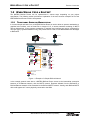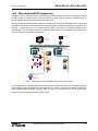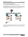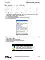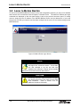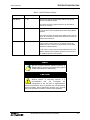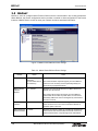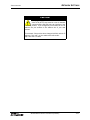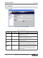
1
MATRIX BACNET ROUTER
USER MANUAL
SMART BUILDING SOLUTIONS
MATRIX BACnet Router User Manual
Part Number 1E-04-00-0132
TM
© 2007 American Auto-Matrix
This document is protected by copyright and is the property of American Auto-Matrix. It may not be used or
copied in whole or in part for any purpose other than that for which it is supplied without authorization. This
document does not constitute any warranty, expressed or implied.
Every effort has been made to ensure that all information was correct at the time of publication. American
Auto-Matrix reserves the right to alter specifications, performance, capabilities and presentation of this
product at any time.
American Auto-Matrix and Auto-Matrix are trademarks of American Auto-Matrix and are not to be used for
publication without the written consent of American Auto-Matrix.
All other brand names or product names are trademarks or registered trademarks of their respective companies or organizations.
WORLD HEADQUARTERS
American Auto-Matrix
One Technology Lane
Export, Pennsylvania 15632-8903 USA
Tel (1) 724-733-2000
Fax (1) 724-327-6124
Email [email protected]
www.aamatrix.com
REVISION HISTORY
6/6/2007 - General Modifications to document
! §2.3.2.3 - Included additional information regarding network termination.
! §3.5 - Modified BACnet Router Settings table to identify the default Device Instance Number
information.
! Deleted un-intentional blank pages at end of §3.9.
4/26/2007 - Initial Manual Release
MATRIX BACnet Router User Manual (6/6/2007)
iii
REVISION HISTORY
iv
MATRIX BACnet Router User Manual (6/6/2007)
ABOUT THIS MANUAL
This manual describes the installation and operation of the MATRIX BACnet Router. This document is
divided into the following sections, each beginning with a table of contents for the section:
! One: Product Overview, describing the features of the MATRIX BACnet Router
! Two: Wiring & Installation, detailing the wiring and installation procedures.
! Three: Configuration, providing detailed steps of configuring the product.
This document may contains certain style and formatting conventions for conveying information in a clear
and concise manner:
! BACnet property names are shown in bold. For example: present_value.
! properties with the associated object specified are listed with the object followed by a semicolon and
then the property. For example: Binary Output 1; present_value.
! Menu commands appear with a “>” symbol between levels. For example: File>Open.
! Italics indicate a section of this manual or another publication.
! The following formats are used to highlight important information:
NOTE
Notes indicate noteworthy information and appear
in boxes with this format separated from the
running text.
CAUTION
Cautions indicate information that may prevent
serious system or user problems and appear in
boxes with this format separated from the running
text.
WARNING
Warnings indicate inforamtion that prevent
personal injury or equipment damage and
appear in boxes with this format separated from
the running text.
MATRIX BACnet Router User Manual (6/6/2007)
v
ABOUT THIS MANUAL
vi
MATRIX BACnet Router User Manual (6/6/2007)
SECTION 1: PRODUCT OVERVIEW
This section provides a product overview of the MATRIX BACnet Router and its usage with American AutoMatrix Native Series products, as well as third-party BACnet products.
IN
THIS SECTION
Overview .................................................................................................................................................................. 1-3
When Would I Use a Router? .................................................................................................................................. 1-4
Traditional Operator Workstation ........................................................................................................................ 1-4
Multi-Vendor MS/TP Integration .......................................................................................................................... 1-5
Multi-Building Communications........................................................................................................................... 1-6
Networking Considerations ...................................................................................................................................... 1-7
MS/TP Medium Rules ......................................................................................................................................... 1-7
MS/TP Network Loading ..................................................................................................................................... 1-7
Specifications ........................................................................................................................................................... 1-8
Quick Start - MATRIX Router Setup......................................................................................................................... 1-9
MATRIX BACnet Router User Manual (6/6/2007)
1-1
PRODUCT OVERVIEW
1-2
MATRIX BACnet Router User Manual (6/6/2007)
OVERVIEW
PRODUCT OVERVIEW
1.1 OVERVIEW
The MATRIX Router is a full-featured BACnet router that directs messages between MS/TP, BACnet/IP
(Annex J) and BACnet/Ethernet (8802-3) networks. Compliant to the BACnet standard (ASHRAE 1352004), the MATRIX Router provides users with the ability to directly monitor and control BACnet system
operations with or without an installed building controller solution.
Within the MATRIX Router product family, several variants exist in which one variant may provide
additional functionality over another. For example, MATRIX-BBO is a single port BACnet router without
BBMD capabilities that provides simple routing of BACnet packets for small, enclosed sites. Table 1-1
provides a breakout of all MATRIX BACnet Router products.
Table 1-1: MATRIX BACnet Router Product Breakout
Product
Description
MATRIX Router
Single MS/TP Port
Part # - MATRIX-BBO
Single MS/TP Port BACnet Router; targeted for small
installations that do not require the need for BBMD
capabilities
MATRIX Router
Single MS/TP Port with BBMD
Part # - MATRIX-BBO-B
Single MS/TP port BACnet Router that includes BBMD
functionality.
MATRIX Router
Dual MS/TP Ports with BBMD
Part # - MATRIX-BBB-B
Two-port MS/TP BACnet Router that includes BBMD
functionality.
MATRIX BACnet Router User Manual (6/6/2007)
1-3
WHEN WOULD I USE A ROUTER?
1.2 W HEN WOULD I USE
PRODUCT OVERVIEW
A
ROUTER?
The MATRIX BACnet Router can be implemented in various ways, depending on your project
specification. The following section provides an explanation of the most common examples of how the
MATRIX BACnet Router would be incorporated.
1.2.1
TRADITIONAL OPERATOR WORKSTATION
In its most simple and basic form, a MATRIX BACnet Router is used to allow an operator workstation or
graphical user interface, such as Auto-Pilot or Integra V.A.C, to access networks consisting of MS/TP
devices Alternatively, if your operator workstation or graphical user interface can only be configured for
one layer type (e.g. BACnet/Ethernet only), the product can be used to route BACnet/Ethernet messages
to BACnet/IP.
Web-Pilot
Auto-Pilot
with BACnet Driver
MATRIX-RTR
Network Controller
75° F
SSB-IOX1
SBC-STAT3
NB-ASCe
Can be used on
all NB Controllers
Packaged Equipment
SSB-DO1
75° F
ipment
SBC-STAT3
NB-AS
Can be used on
all NB Controllers
Packaged Equipment
SSB-AO1
SBC-STAT3
SSB-FI1
BACnet/IP ; BACnet/Ethernet
BACnet/MSTP
STATbus
WAN/Internet
Figure 1-1 Example of a Simple BACnet Network
In the example network sown above, a MATRIX BACnet Router serves as the intermediate connection
between an IP/Ethernet network, and the MS/TP network. Requests initiated from the BACnet/IP or
BACnet/Ethernet network will be forwarded to the BACnet MS/TP network. Visually, each BACnet MS/TP
device will appear as if it were physically connected to the WAN.
1-4
MATRIX BACnet Router User Manual (6/6/2007)
WHEN WOULD I USE A ROUTER?
PRODUCT OVERVIEW
1.2.2
MULTI-VENDOR MS/TP INTEGRATION
A BACnet router is commonly used to third-party vendor BACnet MS/TP products. This approach allows
foe each vendor to communicate on their own physical network without disrupting communications on
another network that may contain another third-party vendor.
Although the BACnet standard defines specific characteristics for each communication layer, vendors are
permitted to implement optional features that could effect network bandwidth performance negatively. For
example, a manufacturer may not support specific MS/TP baud rates or implement slower timing
characteristics. For this reason, isolating vendors from one another using a BACnet router has become
common practice in multi-vendor installations.
Web-Pilot
Auto-Pilot
with BACnet Driver
MATRIX-RTR
Network Controller
MATRIX-RTR
Network Controller
75° F
SBC-STAT3
NB-ASCe
Can be used on
all NB Controllers
Packaged Equipment
ems
nits
Vendor ABC
75° F
ipment
SBC-STAT3
Can be used on
all NB Controllers
NB-ASCe
Packaged Equipment
Vendor ABC
NB-VAV
VAV Boxes
BACnet/IP ; BACnet/Ethernet
BACnet/MSTP
STATbus
WAN/Internet
Figure 1-2 Example of a BACnet Network with Third-Party Devices
In the example above, MATRIX BACnet Routers are used to isolate EIA-485 networks between different
manufacturers. When integrating with third-party MS/TP devices, American Auto-Matrix recommends
using a MATRIX BACnet Router to isolate vendors to their own communication bus. This practice will
greatly reduce the potential for communication issues.
MATRIX BACnet Router User Manual (6/6/2007)
1-5
WHEN WOULD I USE A ROUTER?
PRODUCT OVERVIEW
1.2.3
MULTI-BUILDING COMMUNICATIONS
Many of the communication capabilities within BACnet/IP are dependent on the use of broadcast
messaging. In most IT networks, broadcast messages are blocked or forbidden.
To allow multiple BACnet/IP networks to communicate as flexibly as other traditional Ethernet protocols,
select MATRIX BACnet Routers can be configured to act as a BACnet Broadcast Messaging Device
(BBMD). A BBMD will take broadcast messages originating from one network and forward them onto other
defined networks that have a BBMD or MATRIX BACnet Router configured as a BBMD.
Auto-Pilot
with BACnet Driver
IP Subnet 1
IP Subnet 2
IP Subnet 3
MATRIX-RTR-BBMD
Network Controller
BBMD Enabled
MATRIX-RTR-BBMD
Network Controller
BBMD Enabled
75°F
75°F
SBC-STAT3
NB-ASCe
Can be used on
all NB Controllers
Packaged Equipment
its
s
SBC-STA
T
Can be u
all NB Co
75°F
quipment
75°F
ipment
SBC-STAT3
NB-ASCe
Can be used on
all NB Controllers
Packaged Equipment
ent
SBC-STA
TAT3
NB-A
-ASCe
Can be used on
all NB Controllers
Packa
k ged Equipment
NB-VAV
VAV Boxes
NB-VAV
VAV Boxes
BACnet/IP ; BACnet/Ethernet
BACnet/MSTP
STATbus
WAN/Internet
Figure 1-3 BACnet System Architecture with BBMD
In the example above, messages originating from the head-end or either control network using a MATRIX
BACnet router can be distributed throughout the entire system in a logical and straight-forward approach.
Providing BBMD capabilities within the MATRIX BACnet Router avoid possible network security issues in
an existing IT network.
1-6
MATRIX BACnet Router User Manual (6/6/2007)
NETWORKING CONSIDERATIONS
PRODUCT OVERVIEW
1.3 NETWORKING CONSIDERATIONS
As the MATRIX BACnet router is compliant to the standards of ASHRAE/ANSI 135, there are
considerations that must be kept in mind when designing a BACnet inter-network using this product.
Following these simple guidelines will ensure project success.
1.3.1
MS/TP MEDIUM RULES
Specified by ASHRAE, an MS/TP network shall use shielded, twisted-pair cable with characteristic
impedance between 100 and 130 ohms. The maximum length of an MS/TP network is 4000 feet (1200
meters) using 18 AWG cabling. An MS/TP network shall have no “T” or “star” based network connections.
Networks requiring a longer distance may utilize an optically isolated repeater to extend this limit.
1.3.2
MS/TP NETWORK LOADING
The MATRIX BACnet Router, as well as American Auto-Matrix Native Series unitary controllers, use halfwatt serial driver technology. By law of electrical limitations, a serial network of half-watt devices may
consist of up to 64 devices total.
The MATRIX BACnet Router has been qualified to accept a network of up to 63 additional BACnet MS/TP
devices (router + 63 devices = 64 load limit). This qualification process included verifying electrical network
capacitance provisions, as well as optimal bandwidth speed.
While it may be possible to achieve more than the above mentioned limit using media converters and
repeaters, American Auto-Matrix discourages applications that exceed this limit. If you need to network
more devices as part of an MS/TP network, it is recommended that you purchase additional MATRIX
BACnet Router hardware.
MATRIX BACnet Router User Manual (6/6/2007)
1-7
SPECIFICATIONS
PRODUCT OVERVIEW
1.4 SPECIFICATIONS
1.4.1
!
!
!
!
POWER REQUIREMENTS
connection: 2 position, 5.08mm Eurostyle
NEC Class 2 transformer
11-29 VAC, 50/60Hz, 2.7A max
PTC Protection
1.4.2
!
!
termination count: 1 connection
connection type: RJ-45, female
1.4.3
!
!
!
!
!
!
!
EIA-485 CONNECTION
termination count: 2 connections
connection type: 3 position, 5.08mm Eurostyle
data isolation: GMR Data Isolation
termination: 249ohm, switch selectable
biasing: 3.32k, switch selectable
led: indication for TXD, RXD, Byte-Error, Parity-Error
network load: supports up to 64 BACnet devices maximum
1.4.4
!
!
ETHERNET CONNECTION
CPU
processor: ARM9 with embedded Linux OS
memory: 64MB DRAM and 128MB Flash
1.4.5
!
!
!
OPERATING ENVIRONMENT
temperature range: 32-122 F (0-50 C)
humidity range: 0-80% RH, non-condensing
altitude: up to 2000m
1.4.6
!
!
base module: 5.4 x 9.0” (13.72 x 22.86 cm)
enclosure: 11.0 x 11.0 x 3.50” (27.94 x 27.94 x 8.89 cm)
1.4.7
!
!
!
1-8
DIMENSIONS
AGENCY APPROVALS
FCC
CE
UL
MATRIX BACnet Router User Manual (6/6/2007)
QUICK START - MATRIX ROUTER SETUP
PRODUCT OVERVIEW
1.5 QUICK START - MATRIX ROUTER SETUP
Use the quick-start to learn the order of tasks to perform when you configure MATRIX Router. The
following table lists references where you can go to get additional information.
Table 1-2: Quick Start Setup Information for MATRIX Router
Task
In This Document
In Other Documents
n/a
Site Engineering
Documentation
Mounting - Page 2-4
n/a
1
Determine the MATRIX Router
Device Instance, network numbers,
MAC Address (Unit ID), and baud
rate for the MS/TP network.
2
Mount the MATRIX Router hardware.
3
Connect power to MATRIX Router
and verify it is operating correctly.
Power Requirement - Page 2-5
n/a
4
Configure your PC’s network card
settings
Configuring your Computer - Page 3-3
PC Documentation
Windows On-Line Help
5
Connect to MATRIX Router with web
browsing software and login.
Login to MATRIX - Page 3-4
n/a
6
Configure Ethernet Settings.
Ethernet Settings - Page 3-12
n/a
7
Configure EIA-485 (MS/TP) Settings.
EIA-485 Network - Page 3-6
n/a
8
Configure BACnet Router Settings.
BACnet - Page 3-8
n/a
10
Configure BBMD Settings
BBMD - Page 3-20
n/a
11
Configure Time/Date Settings
Time/Date Settings - Page 3-16
n/a
12
Connect MATRIX Router to BACnet
networks as necessary.
Communication Connection - Page 2-6
n/a
13
Perform a system backup of MATRIX
Router
Backup - Page 3-17
n/a
14
OPTIONAL - Use Auto-Pilot BACnet
to verify that MATRIX Router is
communicating and routing correctly
n/a
Auto-Pilot User Manual
Auto-Pilot BACnet Driver
User Manual
MATRIX BACnet Router User Manual (6/6/2007)
1-9
QUICK START - MATRIX ROUTER SETUP
1-10
MATRIX BACnet Router User Manual (6/6/2007)
PRODUCT OVERVIEW
SECTION 2: W IRING
AND INSTALLATION
This section describes process for installation and wiring of MATRIX BACnet Router hardware and field
network communication connections.
IN
THIS SECTION
Hardware Layout...................................................................................................................................................... 2-3
Mounting .................................................................................................................................................................. 2-4
Power Requirements........................................................................................................................................... 2-5
LED Indication................................................................................................................................................ 2-5
Communication Connections ................................................................................................................................... 2-6
Ethernet Network ................................................................................................................................................ 2-6
Cable Type and Length .................................................................................................................................. 2-6
EIA-485 Network ................................................................................................................................................. 2-7
Cable Type and Length .................................................................................................................................. 2-7
Connecting the MS/TP Network..................................................................................................................... 2-7
Network Termination and Biasing................................................................................................................... 2-7
LED Indication................................................................................................................................................ 2-9
MATRIX BACnet Router User Manual (6/6/2007)
2-1
WIRING AND INSTALLATION
2-2
MATRIX BACnet Router User Manual (6/6/2007)
HARDWARE LAYOUT
WIRING AND INSTALLATION
2.1 HARDWARE LAYOUT
Connections to the MATRIX BACnet Router are made via ports located on the left side of the controller
board. As illustrated below, the device has ports for Main Power, EIA-485 network connectivity and
Ethernet connectivity. Depending on the variant of MATRIX BACnet Router purchased, your application
may involve using only one of the two available EIA-485 network ports. Other unused ports such as RS232 and USB are reserved for future use.
LINE
12-29 VDC / VAC
2.7A (MAX)
J1
PWR PWR
Power Input
PWR
PWR
J3
RS-485
NET +
NET SH
TERM BIAS
N+
SW3
SH
TXD
RXD
PERR
BERR
RS-485
J2
RS-485
NET +
NET SH
RS-485 Termination SW2.1 and SW3.1
N-
TERM BIAS
N+
SW2
NSH
TELCO J5
RS-485 Biasing SW2.2 and SW3.2
U1
TXD
RXD
PERR
BERR
RS-485
A
Termination Off
(Factory Setting)
3.3V
5V
24V
6
1
Biased
(Factory Setting)
10 / 100
Ethernet
U2
USB
RS-232
S2 S1
SW1
ATTN
Figure 2-1 MATRIX BACnet Router Network Controller Board Layout
MATRIX BACnet Router User Manual (6/6/2007)
2-3
MOUNTING
WIRING AND INSTALLATION
2.2 MOUNTING
The MATRIX BACnet Router ships with an approved enclosure consistent with most electrical standards
and regulations. The product is intended for indoor applications only and should be installed in a location
that is dry, away from direct sunlight and free from excessive dust, vibration, and electrical interference.
11.00 inches
Matrix-Router
LINE
12-29 VDC / VAC
2.7A (MAX)
J1
PWR
PWR
PWR PWR
Power Input
J4
J3
RS-485
NET +
NET SH
RS-485
NET +
NET SH
TERM BIAS
N+
SW3
RS-485 Termination SW2.1 and SW3.1
NSH
TXD
RXD
PERR
BERR
RS-485
J2
TERM
TERM BIAS
N+
SH
Termination Off
(Factory Setting)
3.3V
5V
24V
SW2
NTXD
RXD
PERR
BERR
RS-485
A
RS-485 Biasing SW2.2 and SW3.2
U1
TELCO J5
BIAS
6
1
Biased
(Factory Setting)
10 / 100
Ethernet
11.00 inches
U2
USB
RS-232
SW1
ATTN
S2 S1
STATUS 2 STATUS 1
User Button
ELECTRICAL RATINGS:
Power Inputs: Class 2,12-29VDC /VAC 50/60 Hz; Nominal 2.7A maximum
Power Outputs: Class 2 IOX = Power in 1.35A maximum
Communication Signals: RS-232 Class 2,±15VDC maximum; RS-485 Class 2,5VDC maximum
SSB,12VDC 50 mA maximum
ENVIRONMENT: Temperature Ratings:: 0° to 50° C Humidity; 0 to 80% RH non-condensing
Use Copper Conductors Only
Caution: Terminal block torque 3 inch pound maximum
This device complies with part 15 of the FCC rules.
Operation is subject to the following two conditions:
(1) This device may not cause harmful interference.
(2) This device must accept any interference that
may cause undesired operation.
80M7,OPEN ENERGY MANAGEMENT EQUIPMENT.
See Reference Manual No.
1E-04-00-0123 for Instructions for use
U
R
(583a) © American Auto-Matrix, LLC. 2006
Figure 2-2 Mounting Dimensions for MATRIX BACnet Router
NOTE
All equipment must be installed in accordance with
NEC and local codes. For more information on
local codes, please check state/local regulations in
your area.
CAUTION
To prevent damage to any of the electrical
components of MATRIX Router and to ensure that
it continually operates, do not attept to alter any
componentry of the product.
2-4
MATRIX BACnet Router User Manual (6/6/2007)
MOUNTING
WIRING AND INSTALLATION
2.2.1
POWER REQUIREMENTS
The product requires a transformer capable of providing 24VAC power to allow the unit to operate. Use a
UL listed 24VAC transformer.
To connect power to MATRIX BACnet Router, you must use the supplied two-position terminal plug. The
output leads from the transformer should be connected to the terminal plug. The terminal plug is then
connected into the socket marked J1 on the PCB of MATRIX BACnet Router. American Auto-Matrix
recommends using 18AWG cable for power wiring.
J1
PWR PWR
24VAC
Output
Figure 2-3 Connecting Power to MATRIX BACnet Router
WARNING
Do not share the power source for MATRIX
Router with other devices. Damage to the
product as a result of power mis-applications
will void product warranty.
2.2.1.1 LED INDICATION
The PCB of the MATRIX BACnet Router includes diagnostic LEDs, providing user feedback when power
has been connected to the device. When power is connected, all three of the LEDs should be illuminated.
The power diagnostic LEDs is located near the unused modem socket on the PCB.
24V
5V
3.3V
Figure 2-4 Power LEDs on MATRIX BACnet Router PCB
MATRIX BACnet Router User Manual (6/6/2007)
2-5
COMMUNICATION CONNECTIONS
WIRING AND INSTALLATION
2.3 COMMUNICATION CONNECTIONS
Communication connections made to MATRIX BACnet Router should be made with care. To avoid any
possible conflict with existing network communications, it is recommended that firmware/software
configuration of MATRIX BACnet Router be performed before connecting the product to a BACnet
network. Refer to Section 3 for information on software setup and configuration of the product.
CAUTION
It is recommended that all software configuration
be performed prior to physically connecting the
MATRIX Router to any associated communication
networks.
2.3.1
ETHERNET NETWORK
Ethernet is a high-speed LAN widely used in commercial buildings. MATRIX BACnet Router includes an
on-board Ethernet adapter, used to communicate with the device for setup configuration, as well as for
BACnet/IP and BACnet/Ethernet communications.
The on-board Ethernet network interface supports 10Base-T (10Mbps) and 100Base-T (100MBps)
Ethernet connections to an Ethernet network. The MATRIX BACnet Router will automatically switch to
100Base-T operations if other devices and cabling connected to the same subnetwork support this. The
Ethernet network interface is located on the single board computer card of MATRIX BACnet Router, next
to the dual USB ports.
2.3.1.1 CABLE TYPE AND LENGTH
Use an approved Category 5 (CAT5) Ethernet patch cable with RJ-45 plugs to connect MATRIX BACnet
Router to an Ethernet switch or hub. Use professionally manufactured cables to assure transmission rates
and reliability between devices. Distance of length for Category 5 is typically limited to about 300 feet (100
meters).
Pin 8
Reserved
Pin 1
Transmit +
Pin 7
Reserved
Pin 2
Transmit -
Pin 6
Receive -
Pin 3
Receive +
Pin 5
Reserved
Pin 4
Reserved
Figure 2-5 Standard Ethernet Connection Pinout of MATRIX BACnet Router
2-6
MATRIX BACnet Router User Manual (6/6/2007)
WIRING AND INSTALLATION
COMMUNICATION CONNECTIONS
2.3.2
EIA-485 NETWORK
The EIA-485 network connections are used for BACnet MS/TP network communications. MS/TP is a
communications protocol used in BACnet to network multiple devices, such as unitary controllers, together
on one continuous bus. MS/TP uses EIA-485 signaling standards on shielded-twisted pair cabling where
units are networked together in a daisy-chained (multi-drop) format.
Terminals for the MS/TP network are located on the left side of the controller board and are labeled J2 and
J3. Each MS/TP terminal has a connection for Network Positive (N+), Network Negative (N-), and Shield
(SH). The SH terminal is coupled to the housing of the MATRIX BACnet Router and will provide noise
protection for MS/TP communication signals.
The MATRIX BACnet Router must be installed at an physical and electrical end of the EIA-485 network, as
the device is connection intensive. MATRIX BACnet Router should not be wired into a network where it is
“t-tapped” or “starred” into an existing network.
2.3.2.1 CABLE TYPE AND LENGTH
Because BACnet MS/TP is an EIA-485 based network, the standard specifies that MS/TP networks shall
utilize 18AWG, shielded-twisted pair cabling with characteristic impedances ranging from 100 - 130 ohms.
Distributed capacitance between conductors must be less than 30pF/foot (100 pF/m). Distance of length
for EIA-485 is typically limited to about 4000 feet with 32 electrical nodes.
2.3.2.2 CONNECTING THE MS/TP NETWORK
Connect the MS/TP network to the MATRIX BACnet Router’s EIA-485 terminal block. Be sure to maintain
network polarity at all times for MS/TP communications. Failure to do so will result in a loss of network
communications. To prevent against the possibility of ground loops or noise on your 485 network, connect
the drain wire of the 485 to one of the supplied enclosure studs located within the enclosure panel.
N+
N-
Figure 2-6 MS/TP Network Connection
2.3.2.3 NETWORK TERMINATION AND BIASING
Adjacent to each EIA-485 port is a two-position switch block, used to apply termination and biasing to your
MS/TP network. To enable either termination (TERM) or biasing (BIAS), configure the respective switch
into the ON (Up) position.
When applying termination, be certain that it is applied at both ends of your EIA-485 network at the two
end devices. If termination resistors are used, the network will be more heavily loaded and this will change
idle state voltage. In termination applications, biasing should also be enabled to ensure a proper idle state
voltage.
MATRIX BACnet Router User Manual (6/6/2007)
2-7
COMMUNICATION CONNECTIONS
WIRING AND INSTALLATION
TERM BIAS
SW2
Figure 2-7 Termination and Biasing Switches and LED Indicators
2-8
MATRIX BACnet Router User Manual (6/6/2007)
COMMUNICATION CONNECTIONS
WIRING AND INSTALLATION
2.3.2.4 LED INDICATION
Located below the network termination and biasing switches is a set of diagnostic LEDs that can be useful
for troubleshooting network communication problems with a MS/TP network.
TXD
RXD
PERR
BERR
Figure 2-8 Network Diagnostic LEDs
Table 2-1: EIA-485 LED Diagnostics
LED Position
Notes
TXD
This LED will flash anytime data is transmitted by MATRIX BACnet Router to
the MS/TP network. On an active network, this light should flash anytime the
device passes the token to another device or routes a request made by another
device on the BACnet/IP or BACnet/Ethernet network.
RXD
This LED will flash anytime data is received by MATRIX BACnet Router from
the MS/TP network. On an active network, this light should flash anytime there
is activity on the MS/TP network.
PERR
THis LED will flash upon the event a parity error occurs on the MS/TP network.
A parity error is caused by a mismatch between the calculated checksum and
value received with the packet. The most common reason for a packet error is if
more than one unit is attempting to communicate on the network at once,
indicating the presence of a duplicate token or duplicate MAC Address.
BERR
This LED will flash upon the event a byte error occurs on the MS/TP network. A
byte error is caused when information is lost during network communications,
and is detected in the start, stop, or data bit timings. The most common reason
for a byte error is due to devices attempting to communicate on the MS/TP
network at different baud rates.
MATRIX BACnet Router User Manual (6/6/2007)
2-9
COMMUNICATION CONNECTIONS
2-10
MATRIX BACnet Router User Manual (6/6/2007)
WIRING AND INSTALLATION
SECTION 3: CONFIGURATION
This section provides an overview of the process for configuration of the Matrix Router, using the built-in
web user interface discussed previously. Within the section, easy table structures are provided with ranges
of valid values and other additional notes.
IN
THIS SECTION
Configuring your Computer ...................................................................................................................................... 3-3
Configuring your Network Card........................................................................................................................... 3-3
Login to Matrix Router.............................................................................................................................................. 3-4
Control Panel View................................................................................................................................................... 3-5
Navigation Tree................................................................................................................................................... 3-5
System Configuration............................................................................................................................................... 3-6
EIA-485 Network ................................................................................................................................................. 3-6
BACnet..................................................................................................................................................................... 3-8
Network Settings .................................................................................................................................................... 3-10
Web Server Setup............................................................................................................................................. 3-10
Ethernet ............................................................................................................................................................ 3-12
System Settings ..................................................................................................................................................... 3-13
Services ............................................................................................................................................................ 3-13
Status ................................................................................................................................................................ 3-14
System Password ............................................................................................................................................. 3-15
Time/Date Settings............................................................................................................................................ 3-16
Utilities ................................................................................................................................................................... 3-17
Backup .............................................................................................................................................................. 3-17
Factory Restore ................................................................................................................................................ 3-18
Restore ............................................................................................................................................................. 3-19
Updates............................................................................................................................................................. 3-19
BBMD..................................................................................................................................................................... 3-20
MATRIX BACnet Router User Manual (6/6/2007)
3-1
CONFIGURATION
3-2
MATRIX BACnet Router User Manual (6/6/2007)
CONFIGURING YOUR COMPUTER
CONFIGURATION
3.1 CONFIGURING
YOUR
COMPUTER
Before you can access and configure Matrix Router, you must initially configure your PC’s network card
settings for initial communications. The Ethernet port on the Matrix Router is shipped with a default IP
address, located on the door sticker inside of the enclosure. For you to be able to communicate, you must
set the IP address and subnet mask on your computer so they are compatible with the default settings on
the Matrix Router.
3.1.1
CONFIGURING
YOUR
NETWORK CARD
To set your IP address:
1. Open Control Panel by selecting Start>Control Panel. If you are working in Classic Mode, click on
Start, then point to Settings, then click on Control Panel.
2. Double-click Network Connections.
3. Double-click your network card listing to invoke connection properties
4. Click on the Properties button.
Figure 3-1 Network Card Properties
5. Select TCP/IP from the Configuration dialog box. Click Properties.
6. At the Properties dialog, enter a valid and unused IP address that is within the range of the Matrix
Router’s default IP address.
7. Enter 255.255.255.0 as your Subnet Mask.
8. Click OK to save the changes and make them effective.
9. Close the Control Panel.
NOTE
If you are unsure of how to configure your IP
address settings, please refer to Windows on-line
help files or contact your Network Administrator for
additional assistance.
MATRIX BACnet Router User Manual (6/6/2007)
3-3
LOGIN TO MATRIX ROUTER
3.2 LOGIN
TO
CONFIGURATION
MATRIX ROUTER
To connect to the MATRIX BACnet Router for setup and configuration purposes, you may use a standard
web browser such as Windows Internet Explorer or Mozilla Firefox. The default IP address and login
credentials are displayed on the door panel sticker, inside of the product’s enclosure panel. To initially
connect, simply type the IP address of the MATRIX BACnet Router into the address bar of your web
browser. Be sure that your network card has been configured to the correct IP and subnet settings as the
MATRIX Router.
Figure 3-2 Matrix Router Login Screen
NOTE
The web user interface of MATRIX BACnet Router
will support one concurrent session. If more than
one user attempts to log into the web user
interface, the connection request will be rejected
until the current session has been discontinued.
CAUTION
For security purposes, AAM recommends changing
the default password for the admin account after
initial installation.
Refer to section 3.7.3 for
additional procedure information.
3-4
MATRIX BACnet Router User Manual (6/6/2007)
CONTROL PANEL VIEW
CONFIGURATION
3.3 CONTROL PANEL VIEW
The Control Panel of Matrix Router is the default view of the web user interface upon initial access. Control
Panel provides links to various configuration settings for the device. Links are provided for feature sections
of Matrix Router configuration, including:
! EIA-485 Network Settings
! BACnet
! Network Settings
! System Settings
! Utilities
! BBMD
Figure 3-3 Matrix Router Control Panel and Navigation Tree
3.3.1
NAVIGATION TREE
Alternatively, the web user interface of the Matrix Router provides a navigational tree which can be used to
access specific parts of the system with minimal effort. This alternative provides faster access to
subordinate areas of Matrix Router feature settings. To expand a specific section, simply click the plus icon
(+) displayed to the left of each section. To collapse a section once it has been expanded, a minus icon (-)
is provided.
MATRIX BACnet Router User Manual (6/6/2007)
3-5
SYSTEM CONFIGURATION
CONFIGURATION
3.4 SYSTEM CONFIGURATION
The following section provides detailed setup and configuration information for each section of the Matrix
Router. As explained previously, there are a total of six configuration areas for Matrix Router. The areas
are explained in the order of which they are displayed in the web user interface.
3.4.1
EIA-485 NETWORK
EIA-485 Network is used to configure each MS/TP communication port. Expanding this section will display
one or two MS/TP Network listings, depending on the product variant you are using. To configure each
MS/TP network, expand the MS/TP Network section and click Settings. MS/TP Network Settings provides
a method to allow users to setup and configure the MS/TP network port. This section is used to configure
the communication baud rate, a valid MAC address, and other parameters that control and optimize token
passing.
Similarly, a Status page is provided for users to view the current configured MS/TP network parameters
that the Matrix Router is using. The Status page is a read-only display, where as the Settings page is used
to configure the parameters.
Figure 3-4 Matrix Router MS/TP Network Settings
Table 3-1: MS/TP Network Settings
Variable
Baud
Values
Notes
9600, 19200, 38400,
57600, 76800, 115200
Specifies the baud rate of the MS/TP network in which you are
connecting the specific EIA-485 network port onto.
The baud rate configuration for Matrix Router must match the
active baud rate of the MS/TP network you are connecting to.
Contrasting baud rates will result in a loss of communications
across the entire MS/TP network.
3-6
MATRIX BACnet Router User Manual (6/6/2007)
SYSTEM CONFIGURATION
CONFIGURATION
Table 3-1: MS/TP Network Settings
Variable
Max Master
Values
1 - 127
Notes
Specifies the highest assigned MAC Address (Unit ID) that
exists on the MS/TP network.
This value should be configured similar to all other MS/TP
devices on a network.
Max Info Frames
1 - 32
Specifies the number of data frames used on each
communication interval by Matrix Router when routing MS/TP
packets.
This value should be configured at the default value of 10 at all
times. Do not modify this value unless directed to otherwise by
AAM Technical Services.
This Station (ID)
0 - 127
Specifies the MS/TP MAC Address for this EIA-485 port. This
value must be a unique value on your MS/TP network. By
default, this value is set to zero (0) and is the recommended
address for a BACnet Router.
In the event of a token drop, the lowest addressed unit on the
MS/TP network will have rights to generate a new token and
re-establish network communications.
NOTE
Be sure to follow common instllation practices of
BACnet MS/TP network commissiong with regards
to MAC Address/Unit ID Addressing.
CAUTION
If you are connecting MATRIX Router to an existing
BACnet network of third-party devices, it is
recommended
that
you
investigate
the
configuration of the site prior to implementation.
Advanced information about a particular site (IP addressing,
network numbers, device addressing schemes, etc.) can help
reduce the potential for network communication problems.
MATRIX BACnet Router User Manual (6/6/2007)
3-7
BACNET
CONFIGURATION
3.5 BACNET
BACnet is used to configure Matrix Router’s BACnet device communication and routing parameters.
Within BACnet, the Router configuration section provides a method to allow configuration of the Device
Instance of Matrix Router, as well as router port numbers and other associated information.
Figure 3-5 Matrix Router BACnet Router Settings
Table 3-2: Matrix Router BACnet Router Settings
Variable
Device Name
BACnet Device
Instance
Number
Values
Notes
alphanumeric
characters
(recommended limit of
32 characters)
Specifies a unique Device Name for Matrix Router.
0 - 4,194,303
Specifies the unique global Device ID for Matrix Router and
defaults to a value of 100.
This value should be unique throughout your entire BACnet
network, as it is commonly used to specifically identify the
device among a populated network.
This value must be unique throughout your entire BACnet
network and cannot match any other device, as it is used to
specifically address the unit for interrogation by other devices
such as front-ends.
3-8
BACnet Ethernet
Interface
Yes / No
Specifies if BACnet over Ethernet routing is enabled. This
value should be set to Yes in the event that the BACnet IP
Interface option is set to No.
BACnet Ethernet
Network Number
1 - 65534
Specifies the network number for your BACnet over Ethernet
network. Each interconnected BACnet network must have a
network number that is unique throughout the internetwork.
MATRIX BACnet Router User Manual (6/6/2007)
BACNET
CONFIGURATION
Table 3-2: Matrix Router BACnet Router Settings
Variable
Values
Notes
BACnet IP
Interface
Yes/No
Specifies if BACnet IP routing is enabled. This value should be
set to Yes in the event that the BACnet Ethernet Interface
option is set to No.
BACnet IP
Network Number
1 - 65534
Specifies the network number for your BACnet IP network.
Each interconnected BACnet network must have a network
number that is unique throughout the internetwork.
BACnet MS/TP
Network Number
1 - 65534
Specifies the network number for your BACnet MS/TP network.
Each interconnected BACnet network must have a network
number that is unique throughout the internetwork.
BACnet UDP
Port Number
47808 - 47823
Specifies the UDP Port of the Matrix Router, which is used to
establish connection less transmissions over IP with other
BACnet IP enabled devices. This UDP port must be the same
as other BACnet IP enabled devices connected on the same
subnet, especially if the controllers exchange messages only
using BACnet IP (BACnet Ethernet Interface = No).
There are notable exceptions to this rule:
a. When another BBMD is on the same subnet, the UDP ports
of the BBMD must be different
b. Any device on the same subnet that registers with the BBMD
as a foreign device (such as Auto-Pilot BACnet or Integra)
must have a different local UDP port from the BBMD.
Only those controllers with the same UDP port on a subnet will
exchange BACnet IP messages. For best results, always
ensure that controllers on an internetwork use the same UDP
ports.
BACnet APDU
Timeout
3000
Specifies the APDU Timeout for Matrix Router. This value
should be configured at the default value of 3000 at all times.
Do not modify this value unless directed to otherwise by AAM
Technical Services.
NOTE
In MS/TP routing applications, it is recommended
that only BACnet/IP or BACnet/Ethernet be
enabled.
Both should not be enabled
simultaneously for MS/TP.
MATRIX BACnet Router User Manual (6/6/2007)
3-9
NETWORK SETTINGS
CONFIGURATION
3.6 NETWORK SETTINGS
Network Settings contains the raw network configuration of Matrix Router, extending to:
! Web Server Setup
! Ethernet Setup
3.6.1
WEB SERVER SETUP
Web Server Setup provides a method to define the web server configuration of Matrix Router. The default
configuration may need to be changed in order for the product to meet the criteria and security scheme
used in an existing IT network.
Figure 3-6 Matrix Router Web Server Setup
Table 3-3: Web Server Settings
Variable
Value
Notes
Hostname
alphanumeric
characters (8 max)
Specifies a hostname for Matrix Router. When interrogated by
another network device such as a network server, Matrix
Router will identify itself using this name.
Domain
alphanumeric
characters (64 max)
Specifies the Domain name of the Ethernet network in which
Matrix Router will be connecting to. This information is required
in order for the product to communicate via an Internet
connection and can be obtained by contacting the network
administrator of the network you are connecting the product
onto.
Port
0 - 65536
Specifies the TCP/IP Port number used to access the web user
interface of Matrix Router. This value should be set to 80, as
this is the registered port for HTTP traffic for most networks,
unless otherwise specified by a network administrator.
3-10
MATRIX BACnet Router User Manual (6/6/2007)
NETWORK SETTINGS
CONFIGURATION
CAUTION
Modifying the Web Server Port from the default
value of 80 (HTTP) may result in a loss of standard
communications with the web user interface of the
product. If you change the port number, be sure to
address the port number in the address bar of your web
browser.
For example, if the port has been changed to 8544, and the IP
address is 192.126.1.10, the address bar will contain:
http://192.168.1.10:8544.
MATRIX BACnet Router User Manual (6/6/2007)
3-11
NETWORK SETTINGS
CONFIGURATION
3.6.2
ETHERNET
Ethernet provides a method to configure the IP addressing scheme of the Matrix Router, as well as server
referencing for DNS (Domain Name Service). In order for Matrix Router to communicate on a network, it
uses a static IP address.
Figure 3-7 Matrix Router Ethernet Settings
Table 3-4: Ethernet Settings
Variable
Value
Notes
IP Address
nnn.nnn.nnn.nnn
Specifies the IP address assigned to Matrix Router. Follow IP
addressing conventions and rules for the target network you
are installing Matrix Router onto.
Subnet Mask
nnn.nnn.nnn.nnn
Specifies the netmask value for transmissions onto the
network. Follow IP netmasking conventions and rules for the
network you are installing Matrix Router onto.
Default Gateway
nnn.nnn.nnn.nnn
Specifies the IP address of the gateway the device uses to
connect to an IT network.
Preferred DNS
Server
nnn.nnn.nnn.nnn
Specifies the preferred DNS Server IP-address, which is used
to translate a Domain name (such as the one contained within
the web server setup). This address is typically used for all
DNS transactions carried out by Matrix Router’s web server.
Alternate DNS
Server
nnn.nnn.nnn.nnn
Specifies the alternate DNS Server IP-address, which is used
to translate a Domain name (such as the one contained within
the web server setup). This address is a fall-back address
used in the event that the Preferred DNS Server address
cannot be reached.
3-12
MATRIX BACnet Router User Manual (6/6/2007)
SYSTEM SETTINGS
CONFIGURATION
3.7 SYSTEM SETTINGS
System Settings contains the device configuration of Matrix Router.
! Services
! Status
! System Password
! Time/Date Settings
3.7.1
SERVICES
Services provides a method to allow users to monitor and command services executed within the Matrix
Router. Given the Router variant of this product is designated for BACnet, the only service that can be
monitored from this location is the BACnet service. A green orb displayed next to the service indicates that
BACnet communications is active within the Matrix Router.
Figure 3-8 Matrix Router Services
This section also provides a mechanism to issue a restart command to Matrix Router, and to manually start
and stop BACnet communication services. Simply click the drop-down menu, choose you selection, then
click Submit to execute the desired action.
CAUTION
Submitting a Restart command will reboot MATRIX
Router. During the reboot process, there will be a
temporary loss of communicatins.
The reestablishment of network communications may
take a few moments.
MATRIX BACnet Router User Manual (6/6/2007)
3-13
SYSTEM SETTINGS
CONFIGURATION
3.7.2
STATUS
Status provides a method to view the system status of the Matrix Router. Detailed operating information
regarding the performance statistics of the device can be found here. Information within this screen is
typically used for advanced troubleshooting purposes.
Figure 3-9 Matrix Router Status
Useful user information included within this section includes the product serial number, software and
kernel revision information. Additional information regarding the EIA-485 statistics and how long Matrix
Router has been running (uptime) since the last reboot can also be viewed.
3-14
MATRIX BACnet Router User Manual (6/6/2007)
SYSTEM SETTINGS
CONFIGURATION
3.7.3
SYSTEM PASSWORD
System Password provides a method to change system credentials, required to access the web user
interface. Refer to the inside housing sticker for information on default credentials.
Figure 3-10 Matrix Router System Password
To change the system password, you will be required to enter:
! The case-sensitive old password
! The case-sensitive new password
! Re-enter the case-sensitive new password for verification
System passwords can be made up of any printable characters, containing characters from each of the
following three groups as displayed in Table 3-5. Passwords must be at least 6 characters in length. It is
recommended that users implement “strong” passwords consisting of characters from all three groups
listed below.
Table 3-5: Valid System Password Character Groups
Group
Examples
Letters (uppercase and lowercase)
ABCDEFGHIJKLMNOPQRSTUVWXYZ
abcdefghijklmnopqrstuvwxyz
Numbers
0
Symbols (all characters not defined
as letters or numbers)
underscore ( _ )
hyphen ( - )
period ( . )
1
2
3
4
5
MATRIX BACnet Router User Manual (6/6/2007)
6
7
8
9
3-15
SYSTEM SETTINGS
CONFIGURATION
3.7.4
TIME/DATE SETTINGS
Time/Date Settings provides a method to allow users to set the time and date of Matrix Router and its onboard real time clock.
Figure 3-11 Matrix Router Time/Date Settings
The time format can be displayed in either a 12-hour format (traditional), or in a 24-hour format (military).
The System Time can be set by selecting the applicable drop down and selecting the hour and minute
interval. Finally, the System Date can be set by clicking the Calendar icon.
Click Submit next to each variable to save and make changes effective.
3-16
MATRIX BACnet Router User Manual (6/6/2007)
UTILITIES
CONFIGURATION
3.8 UTILITIES
The Utilities section contains system utilities to perform essential configuration tasks such as:
! Backup
! Factory Restore
! Restore
! Updates
3.8.1
BACKUP
Backup provides a method to perform a full system backup of all configuration properties modified within
the web user interface of the Matrix Router. To initiate a full system backup, simply navigate to this area of
the web user interface and click Submit to start the process. Once the process has been completed, the
web user interface will provide you with a hyper link that will allow you to download a .BIN file, which
contains the setup configuration of the device.
Figure 3-12 Matrix Router Backup
NOTE
The .BIN file generated is an encrypted file that can
only be interpreted by the web user interface of
MATRIX router.
Do not attempt to modify
parameters of this file.
MATRIX BACnet Router User Manual (6/6/2007)
3-17
UTILITIES
CONFIGURATION
3.8.2
FACTORY RESTORE
Factory Restore provides a method to command the Matrix Router to a factory default configuration state.
This could be used to clear a bad configuration from the device. As the term describes, this action will
place Matrix Router into a state where all configuration will be cleared, and IP address settings will be
defaulted to factory settings. It is recommended that this utility be used locally at a site, rather than over a
long-distance connection.
Figure 3-13 Factory Restore Utility
3-18
MATRIX BACnet Router User Manual (6/6/2007)
UTILITIES
CONFIGURATION
3.8.3
RESTORE
Restore provides a method to download a previous backup file to Matrix Router for recovery purposes. To
restore a Matrix Router, click Browse to navigate through your PC’s file system for the backup file. Once
located, open the file and click Restore.
Figure 3-14 Restore Utility
Once a backup file has been submitted to the Restore utility, Matrix Router will process the file and restart
in order to make the changes effective throughout the system.
3.8.4
UPDATES
Updates provides a method to download a firmware update file to Matrix Router. This section also provides
a comprehensive log of all firmware updates and factory restore actions applied to the device. To apply a
firmware update, click Browse to browse your PC’s file system for the applicable firmware update. Once
located and listed in the dialog, click Upload to send the firmware update to Matrix Router.
Figure 3-15 Updates Utility
Matrix Router will process the update file. Dependent on the update and the changes made, the Matrix
Router may reboot in order to apply the update.
MATRIX BACnet Router User Manual (6/6/2007)
3-19
BBMD
CONFIGURATION
3.9 BBMD
BBMD provides a method for users to setup and configure the broadcast distribution table (BDT) used to
reference other Matrix Router BBMD products or third-party BACnet Routers with BBMD enabled. By
default, a read only entry will automatically exist for the Matrix Router under configuration.
Figure 3-16 BBMD Configuration
Table 3-6: BBMD and BDT Settings
Variable
Values
Notes
IP Address
nnn.nnn.nnn.nnn
Specifies the IP address of the BBMD or device acting as a
BBMD on the IP network.
Port #
47808 - 47823
Specifies the UDP Port configuration of the BBMD or device
acting as a BBMD on the IP network
Network Mask
nnn.nnn.nnn.nnn
Specifies a mask of the network of the BBMD being entered.
Typically set to 255.255.255.255, which indicates that BACnet
IP messages go only to the BBMD of interest and to no other
devices on the subnet.
Changing this setting (most commonly to a 255.255.255.0) is a
common cause of IP routing issues, since most IP routers will
not allow messages to be forwarded to multiple devices as a
security provision. In nearly all applications, leave this setting
for each BBMD at 255.255.255.255.
3-20
MATRIX BACnet Router User Manual (6/6/2007)