1
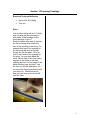
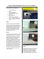
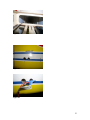
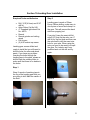
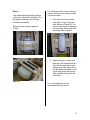
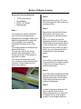
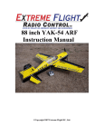
Semi Scale Yak-54, ARF 102” Generation II
ASSEMBLY MANUAL
Specifications
Wingspan:
Length Including Spinner:
Wing Area:
Weight (RTF):
Recommended Engines:
Gas
102 in
91 in
1,975 sq in
25-28 lb
100-110cc
Table of Contents
Quique’s Aircraft Company
Covering Colors
Going Over the Covering
Hardware Supplied
Additional Required Tools and Adhesives
Servo Selection
Using the Manual
Warning
Warranty Information
Section 1-Preparing Fuselage
Section 2-Horizontal Stab Installation
Section 3-Elevator, Rudder and Aileron Control Horn Installation
Section 4-Preparation and Installation of Hinges
Section 5-Wing Anti-Rotation Pins and Servo Installation
Section 6-Tail Wheel Installation
Section 7-Elevator Servo Installation
Section 8-Rudder Servo and Pull/Pull Installation
Section 9-Engine Mounting
Section 10-Landing Gear Installation
Section 11-Fuel Tank Installation
Section 12-Engine Cowling
Section 13-Canopy Installation
Section 14-Radio Equipment
Balancing the Model
Control Throws
Preflight at the Field
DA100 and 3W 106 Engine Template
3W-106 Canister Support Dimension
3
4
4
5
6
8
8
8
8
9
10
12
14
17
21
22
24
26
33
35
37
39
40
44
45
48
49
50
2
Quique’s Aircraft Company
3410 Saint Paris Pike
Springfield, OH 45504
Phone: (937) 629-0339
Fax: (937) 629-0335
Email: [email protected]
Website:www.QQAircraft.com
Online-Support:http://www.rcuniverse.com/forum/forumid_437/tt.htm
Quique and I want to express our thanks to you for choosing our 102” Yak-54.
We think that you will enjoy one of the best flying model aerobatic airplanes
available. It is patterned after the 37% Yak-54 which took First Place honors at
2006 Don Lowe Masters Champion and 2006 Tucson Free Style Champion. The
2003 Free Style Championships in Lakeland Florida, First Place at the Don Lowe
Master competition 2003 & 2004, First Place Tucson Shoot Out 2004 Free Style,
First Place XFC 2004, precision and free-style and Third Place at the
Tournament of Championships in Las Vegas in 2002.
We have tried to prepare the best assembly manual possible along with best
support on our line of Aircraft. We are happy to announce that we have a support
forum on www.Rcuniverse.com that is being led by
Mr. Reza Gholamipour. Imagine, you are building your plane during the weekend
when we are closed and you desperately need to get an answer to your question
to continue building. Well we are happy to tell you that your question has most
likely already been asked and answered on the RC Universe forum “Quique’s
Aircraft Support.” If not, just post your question on the most appropriate thread
and have the answer in matter of hours.
Also we would like to ask you to check our support forum for any updates that
may pertain to your aircraft before starting your assembly process.
Good flying to you!
Quique, Sandra, Wayne, Molly and Reza
3
Covering Colors
Ultra-cote covering used on this 102” Yak-54 can be purchased from Horizon
Hobbies Website. The codes are as follows:
Deep Blue
True Red
White
Bright Yellow
Hanu873
Hanu866
Hanu870
Hanu872
Going Over the Covering
Before beginning the assembly of your Yak-54, remove each part from its bag for
inspection. If you find any wrinkles in the covering, use a heat gun or covering
iron to remove them. Use caution while working around areas where the colors
overlap to prevent separating the colors. Make sure you go over the edges with
your iron as well.
4
Hardware Supplied
Pull/Pull Rudder
30 Hinges and Wing pins/clips
Tail Wheel
Aileron/Elevator Titanium rods & ball links
Fuel Tank
Canopy hardware
Cowl hardware
Optional Dubro Hardware to complete your Assembly:
Wheels and Axles
Control Horn System
5
Additional Required Tools and Adhesives
• Covering/Trim iron
• Xacto knife, #11 blade
• Pacer hinge glue (PT-55)
• 5, 15 and 30-minute epoxy
• Petroleum jelly/Lithium grease
• Acetone/Alcohol swabs
• Felt-tip marker
• Pencil and Marker
• Ruler
• Drill
• Drill bit 1/16”,1/8”, ¼”, 3/16”, #33, #25, #54
• Wire cutter
• Course and fine sandpaper
• Thin, medium and thick C/A
• Full threaded servo mounting screws
• Sullivan inner nyrod
• Pliers
• Masking tape
• Ultra fine point sharpie
• Electrical tape
• Double-sided tape
• Rat-tail file
• Pin vise
• Round toothpick
• Velcro
• Thread Locker
Extensions:
• (2) 24” and (2) 3” servo extensions for Ailerons
• (2) 48” servo extension for Elevators
• (1) 24” servo extension for throttle
• (2) 12” servo extension from Aileron matchbox to Receiver
6
All Other Parts Required to Complete the Aircraft
•
•
•
•
•
•
•
•
•
•
•
•
•
DA100 or similar engine
MTW 75 Canisters with 50mm drop down header or Stock Mufflers or similar
set up for different engine
1.5” Aluminum stand offs
(8) JR 8611a or similar Digital servo
(1) JR 4735 or similar analog servo
(4) 1.5” and (2) 1.25” single side Aluminum servo arms and (2) 3” double side
aluminum servo arm for all control surfaces. (1) Plastic servo arm for throttle.
(1) 4000 mah Li-Ion Duralite plus battery or similar for Receiver
(1) 2000 mah Li-Ion Duralite plus battery or similar for ignition
(1) Heavy-duty regulated failsafe switch such as Duralite #65060-HD for
receiver
(1) Duralite digital switch with built-in 5.5v regulator for ignition (P/N #80401)
or similar
(1) 8-channel receiver
(1) 4 ½” Airwild Extra style spinner or similar
(1) NX or Mejzlik 27x10 2-Bladed Prop
7
Servo Selection
The servos used for the control surfaces of this Yak-54 are as follows:
Ailerons (4), JR 8611a
Elevator (2), JR 8611a
Rudder (2), JR 8611a
Throttle, any standard analog servo
Make sure you use same or equivalent torque servos that are digital.
Please do not risk your plane by using low torque or analog servos.
This Yak-54 has large control surfaces and fully capable of any maneuvers that a
pilot is able to perform. Therefore, using weak servos will increase chance of
flutter and may result in a crash.
Using the Manual
This manual is divided into sections to help make assembly easier to understand
and to provide breaks between each major section. Remember to take your time
and follow the directions.
Warning
I am sure that for the most of you this is not your first venture into the World of
flying radio-controlled aircraft. For those of you that may be entering this exciting
sport early on in your modeling experience and for you with vast experience, I
think we all need to be reminded of the possible dangers that are associated with
a high performance aircraft of this type. This is not a toy. This aircraft must be
flown in a safe manner at all times. You should always do a preflight check
including control surfaces hook-ups, radio operation, (please refer to your radio
equipment instruction manual for range checks and other pertinent related
information) and all other checks relating to the safe operation of this aircraft.
Warranty Information
Quique’s Aircraft Company guarantees this kit to be free from defects in both
material and workmanship at the date of purchase. This warranty does not cover
any parts damaged by use or modification. In no case shall QQAC’s liability
exceed the original cost of the purchased kit.
Customer is responsible to check all the components upon receiving of his
aircraft and notify QQAC in case of any visible damage to any parts. Customer
should not proceed with building the aircraft as some damages can compromise
the integrity of the structure of the aircraft, resulting in more damages. In no case
will such damages be covered by QQAC.
8
Section 1-Preparing Fuselage
Required Tools and Adhesive
•
•
Xacto knife, #11 Blade
Trim Iron
Step 1
Use an Xacto knife with a # 11 blade
and cut away the film covering on
both sides of the fuselage for the
wing openings, Figure 1.
Some modelers may want to overlap
the film covering down inside the
fuse in the opening for the wing. For
example this type of an opening for
the wing may be done as follows.
Simply cut the film about 1/8 of an
inch to the inside of the opening for
the wing. You may then bend this
extra 1/8 inch flap of film over ninety
degrees to the inside of the fuse
opening and iron it to the edge of the
balsa sheeting over the foam. Use
the trim iron for this application. Do
not touch the foam (bead board) with
your trim iron. Watch how much
heat you use here as too much will
melt the foam.
Figure 1
9
Section 2-Horizontal Stab Installation
Required Tools and Adhesive
•
•
•
•
•
•
•
Rat-tail File
Acetone
Xacto knife, #11 Blade
Course sandpaper
Thin CA
5-minute epoxy
Microballons
Step 3
Prepare the C/F anti-rotation pins by
using coarse sandpaper and rough
up the end of the pin where it will be
inserted in the second rib in the
H.Stab. Now clean the pins with
acetone or alcohol to remove any
possible grease or dirt.
Step 1
Step 4
Use an Xacto number 11 blade and
cut open the film covering over the
area at the rear and on both sides of
the fuselage for the horz. stab. tube
and for the anti-rotation pin
openings. Also open the covering
where the two screws will
be used to attach both the left and
right horz. stabs in place.
Use 5-10 minute epoxy to attach the
pin to the number two rib that is
inside the horz stab. Then use thin
C/A to attach the pin to the root rib of
the horz stab.
Step 5
Add a little extra fillet of epoxy
with micro-balloons on the inside rib
around the anti-rotation pin to insure
a strong bond for the pins.
Figure 2
Step 2
Step 6
Open the long slots where the
rudder cables will pass through the
rear of the fuse.
If the anti-rotation pins fit too tightly
in the fuse sides, it will be necessary
to open the
10
holes in the fuse sides slightly with a
small rat tail file.
Very Important:
After completing the model and flying
it, in case you noticed any play in the
stab, please glue the horizontal stab
tube in place in the fuselage with
epoxy and micro-balloons.
11
Section 3-Elevator, Rudder and Aileron Control Horn Installation
Required Tools and Adhesive
•
•
•
Xacto knife, #11 Blade
5-10 minute epoxy
Alcohol Swab/Alcohol and
paper towel
The Optional Du-bro package that
we offer will have everything you
need to complete the following steps,
otherwise please use your
alternative.
Elevator Horn Installation
covering film on the top of the
elevator.
Be sure that you do not put too much
epoxy in the hole and on the screw.
If necessary,
you may want to put a small pin hole
in the top covering just above the
hole to allow the excess epoxy to
escape. Clean excess epoxy with an
alcohol swab.
Step 1
Locate the elevator control horn hole
that is covered by ultracote. Remove
the covering from bottom by
xacto knife.
Step 2
Attach the Du-Bro Heavy Duty
Control Horn System, Cat. No. 866.
The hole is pre-drilled in each
elevator to accept the 8-32 X 2”
socket head cap screw.
Use a Dremel cut off wheel and
remove the socket head of the 832 socket head screw just below the
screw head so you preserve as
much length of the screw as
possible.
Step3
Clean the screw with alcohol,l and
epoxy in place through the bottom of
the elevator in the hard point
provided. Insert full depth in the hole
with the head end of the cut off 8-32
screw entering all the way to the
Figure 3
Step 4
After insertion the 8-32 screw should
protrude to a length of 1 inch
measured from the bottom of the
elevator.
Rudder Control Horn Installation
Step 1
Locate the pre-drilled rudder control
horn hole that is covered by ultracote
and remove the covering by xacto
knife or a solder.
Step 2
12
Use the Dubro heavy duty dual pullpull system Cat. No. 882. Insert the
8-32 threaded rod for the rudder
control horn.
8-32X3 round Slotted/Phillips Zinc
Machine screw at Lowes or similar
supplier. We include those screws in
our optional Du-Bro package.
Step 3
Step 3
Take the screw out and apply a thin
layer of epoxy/alcohol inside the hole
to strengthen the inside walls.
Step 4
Proceed with final installation of
Dubro Cat. No 882. See Figure 4.
Use epoxy and screw the machine
screw into the hole provided until it
reaches the top of the aileron. Cut off
the head of the screw leaving a
length of the control horn measured
to the bottom of the aileron as
follows:
For the inboard horn, 1 inch, for the
outboard horn 1-1/4 inches. After
you have installed the servos, you
are ready to hook up the linkage.
Figure 4
Aileron Horn Installation
Step 1
Locate the aileron control horn hole
and servo locations that are covered
by ultracote. Remove the covering
from bottom by xacto knife.
Step 2
Use the Du-bro Heavy Duty Control
Horn System, Cat. No. 866. However
the 2” 8-32 socket head cap screw
provided is not long enough for the
aileron control horn. Purchase
13
Section 4-Preparation and Installation of Hinges
Required Tools and Adhesive
•
•
•
•
Xacto knife, #11 Blade
Lithium grease/Petroleum Jelly
Toothpicks
Pacer hinge glue (PT-55)
The hinge slots are already cut in the balsa at all hinge locations on both the
fixed surfaces and the moveable surfaces. However, they are covered up with
the covering film so they may be a little difficult to see and locate. Look closely
and you will find the hinge slots. Run your finger along the edge where the
hinges are located. You should feel a little depression in the film at each hinge
slot under the film.
Number of slots and hinges per control surface are as follows:
Aileron 9
Elevator 4
Rudder 4
14
Step 1
Step 3
Use a # 11 blade to open the flat
hinge slot.
The hinge slots will have to have a
larger opening cut out just on either
side, top and bottom, of the pivot
point on both surfaces. So you will
need to open the area in the fixed
and moveable surfaces of the
ailerons, elevators and rudder.
Step 2
Use a #11 blade and make a wedge
tapered opening to accept the
pinned hinge area of the hinge. See
Figure 5 & 6.
Make a V- cut in the fixed and
control surface area along the slot
location of the flat hinge. This
additional V- slot will insure that the
hinge will insert far enough into the
hinge slot so it is in the proper
location and provide enough depth
for each hinge. The gap between the
flying surface and the control surface
needs to be at a minimum. However
we have to have enough of a gap so
full deflection is possible. Check
deflections before bonding hinges.
Step 4
Check the gap on each control
surface. The gap should be at
minimum and yet make sure you get
the maximum throw. This procedure
will take some time to do all of the
hinges but take your time and do a
nice job. As you do each hinge and
check out the proper depth and
shape of the V-slot necessary for
each hinge, the time involved to do
each subsequent hinge will lessen.
Figure 5
Before you glue the hinges in
place:
Dry fit the control surfaces to fixed
surfaces. Make sure everything is
lined up and full deflections are
possible.
Take some lithium grease or
Petroleum jelly and apply a very
small amount on both sides of the
hinge point on the flat hinges.
Quique used a round toothpick. See
Figure 7 This will help prevent any
glue in the pivot point.
Figure 6
15
Be very careful not to get any grease
etc. on the flat part of the hinges.
Also remember that you always glue
the hinges in to the fixed surfaces
first, let the glue harden before you
then glue in the control surfaces.
Remember to check for the correct
hinge gaps for rudder, elevators and
ailerons. You must have the correct
gap to insure the maximum control
deflection necessary for the best 3-D
aerobatics. For hinge attachment we
like to use Hinge Glue by Pacer.
You may use epoxy if you wish. If
you use epoxy, use an epoxy with a
curing time that will give you enough
time to work the hinges in place
before the epoxy hardens.
For each aileron, cut 44 1/4”x1” of
bright yellow ultracote and seal the
hinge line from top using a straight
edge and trim iron.
For each half elevator, cut
14 1/4”x3/4” of bright yellow ultracote
and seal the hinge line from top
same way as you did your ailerons.
Following figures show what it would
look like if you use bright yellow
ultracote to seal the hinge line from
top.
Figure 8
Figure 7
Step 5
Sealing the Control Surfaces
After you are done hinging the
ailerons and elevators, make sure
you seal the hinge line by using clear
ultracote or bright yellow ultracote for
best appearance. Unsealed control
surfaces may cause flutter like
aileron flutter, which may cause your
plane to crash, where sealed control
surfaces will give you better and
crisper response in flight.
Figure 9
16
Section 5-Wing Anti-Rotation Pins and Servo Installation
Required Tools and Adhesive
•
•
•
•
•
•
•
•
•
5-15 minute epoxy
Ruler
Coarse sandpaper
Acetone/Alcohol swab
Thin C/A
Micro balloons
(2) 24” servo extensions
(2) 1.5” aluminum servo arms
Long rod such as 48” Dubro
rod.
Figure 10
Step 1
Prepare the aluminum anti-rotation
pins by using coarse sandpaper and
rough up the end of the pin where it
will be inserted in the second rib in
the wing. Now clean the pins with
acetone or alcohol to remove any
possible grease or dirt.
Step 2
Install the anti-rotation pins using the
following dimensions. The front pin
should measure 10.5mm. Note: the
picture showing the measurement
with the ruler may not look like
exactly 10.5 however 10.5 mm is the
correct distance from the root rib to
the center hole for the keeper clip at
the end of the anti-rotation pin. Also
this ruler starts at zero, yours may
not start at zero. The rear pin should
measure 8 mm from the root rib to
the center of the hole. The front and
rear pin should have the hole in a
vertical position.
Figure 11
Step 3
Apply 5-minute epoxy in the second
wing rib holes. Lay the wing flat on
the table to insert the anti-rotation
pins. Now insert the pins to the
correct depth. Again, check the hole
17
in the end of the pins to make sure
the front and rear pins are vertical as
this is very important
Step 6
Step 4.
Let the epoxy harden. Stand the
wing on its wing tip and run some
thin C/A around the root rib. Wipe
away any excess. Do this several
times which will help to seal the pin
to the hole in the root rib.
Step 5
You will find some ¼” I.D. O-rings
and washers with the wing antirotation package of parts. Use thin
C/A and glue the O-ring to the
washer. After you have installed the
wings to the fuse you will use this Oring and washer to slide over the
anti-rotation pin before you put the
keeper clip in the hole in the antirotation pin.
After the C/A has hardened, make a
fillet of 15 minute epoxy and micro
balloons and apply on the inside of
the root rib. I used a small length of
3/16” wooden dowel to apply the
epoxy-micro balloon mix.
Figure 14
Step 7
Figure 12
Now install the aileron servos the
way that output shaft is towards the
leading edge of the wing.
Figure 13
18
Step 8
Plug a 24" servo extension onto the
outboard servo. Either tie the servo
leads together, using a commercially
available connector, or use unwaxed
dental floss to secure the extensions
to prevent them from coming
loose during flight.
Step 9
To run the servo extensions, use a
long rod and make a little hook at
one end of it. Pass it through the
wing panel and connect your servo
lead to the hook with masking tape
and pull it through.
Figure 17
Step10
Use 3” extension for inboard servo
and install the servo.
Step 11
Use 1.5” aluminum servo arms.
Step 12
Figure 15
Measuring from hinge line vertically
to pivot point on the Dubro Control
Horn connector should be at 1.7”
inches for the proper amount of
aileron throw. Hook the servo arm to
the control horn using the provided
4/40 titanium rods.
Use provided ball links to complete
the installation.
Note that you don’t need more throw
than 45 degrees for Ailerons. Don’t
alter the set up to get more than 45
degree deflection.
Figure 16
19
Figure 18
Step 13
You need to use matchboxes for
best results.
Make sure that servos are not
fighting each other throughout the
travel. Follow matchbox instructions
for proper set up.
20
Section 6-Tail Wheel Installation
Required Tools and Adhesive
•
•
•
•
Drill
Thread lock
Course sandpaper
5-minute epoxy
Step 1
Insert the three screws to attach the
tail wheel bracket.
Figure 19
Step 2
Attach the small piano wire control
steering arm and be sure to use
thread lock on all the screws. Make a
little double bend in the wire control
steering arm so it will fit in the rudder
steering point in the rudder. Use the
small ball link provided to insert into
the bottom of the rudder to accept
the steering arm wire.
Step 3
To attach the ball joint in the bottom
of the rudder, drill a hole with the
correct diameter and epoxy the ball
joint in place. For better adhesion,
rough up the shaft end of the ball
joint that is to be inserted into the
bottom of the rudder with course
sandpaper.
21
Section 7-Elevator Servo Installation
Required Tools and Adhesive
•
•
•
•
(2) 48” servo extension
Pin vise
1/16”drill bit
1 1/4” aluminum servo arms
Step 1
Install the servo in its place.
Figure 20
Step 2
Pull the servo wire through the rib
access holes closest to the tube
sleeve.
Step 3
Install a 1-1/4” aluminum servo arm
on servo output shaft.
Step 4
Figure 21
Use a 2 inch Hanger 9 titanium
control rod and on the servo end of
the control rod, use a 4/40 Ball Link.
The plastic Du-bro control linkage
does not have any threads taped for
the 4/40 control rod so you may put
the left hand threaded end of the
control rod there. Then the 4/40 ball
link that you use can be the standard
right hand threaded version.
Step 5
Run 48 servo extensions from
servos to receiver.
Step 6
To run the servo extensions, use a
48” rod and make a little hook at one
end of it.
Step 7
Pass it through the fuselage and
connect your servo lead to the hook
with masking tape. Pull it through the
fuse.
22
Figure 22
Figure 23
Figure 24
23
Section 8-Rudder Servo and Pull/Pull Installation
Required Tools and Adhesive
•
•
•
•
•
Z-42 thread locker (Pacer)
Thin C/A
0.05 Allen wrench
(4) full-threaded servo screws
Wire Cutter
You will need a total of 500 inch
ounces of torque on the rudder. The
rudder servo tray has three servo
openings. Example, if you are using
JR 8411 servos, you should use
three servos. If you are using the JR
8611 servos, you will only need to
use two. We are using two JR
8611servos in this manual. For the
pull/pull control system for the
rudder, you will need to cross the
cables. Be sure to put a length of
Sullivan Gold-N-Rod # 504 over one
of the cables to prevent possible RF
signal generation that is just waiting
to crash your plane.
Step 1
Install the rudder servos with the
output shaft toward the front of the
fuselage.
Step 2
Check provided pull/pull cable to
make sure its covered with plastic, if
not take a piece of inner Ny-Rod and
slip a long piece over one of the
cables. This will prevent radio
interference.
Step 3
Insert the cable connector sleeve
over the cable through the small end
of the connector. Tie a knot and pull
the cable back thru the threaded end
of the connector and insert the 4-40
threaded rod and tighten with a
0.050 Allen wrench. Important: Be
sure to use Pacer Z-42 Thread
Locker or similar on the 4-40
threaded rod that goes into the cable
connector sleeve.
Figure 25
Make careful measurements on the
final length needed before you attach
the cable connectors on the final end
of the cable. You do have some
length adjustment available but most
of that adjustment should be for the
final cable tensioning process.
24
Figure 26
Figure 27
Step 4
Step 8
Attach the double CF arm to your
servo arm and mark the holes you
want to use to couple the servo to
your second servo.
After you fly the airplane for 3 to 5
flights you will need to readjust the
cables because they will get to “their
place”. After that you should check
the cables every 50 flights or so.
Step 5
Drill the holes and adjust your pullpull system with the first servo that
has the double CF arm.
Step 6
Attach the second servo to the first
servo by using provided ball links
and 1.5” titanium rods.
Step 7
Connect your matchbox and adjust
the travel of both servos according to
your matchbox instructions. Make
sure that servos are not fighting each
other through out their travel.
25
Section 9-Engine Mounting and Throttle Control Installation
Required Tools and Adhesive
•
•
•
•
Drill
1/8”, ¼” drill bits
Sullivan Locking Sleeve Ball
Joints S560
2-56 Rod
DA100 and 3W 106 engine mounting
templates are the same.
Stand off size:
DA100 with stock mufflers: 1.5”
DA100 with Canisters: 1.5”
3W 106: ¾”
Step 2
Mark the four engine mounting bolt
holes through the template and onto
the firewall and drill the holes.
Step 3
Insert ¼” blind nuts from inside the
firewall. Note that the bottom two
blind nuts need to be trimmed in
order to fit in the box.
Engine template provided at the end
of this manual is the same for above
engines and exhaust combinations.
DA100 Engine Installation
Step 1
Figure 29
Snap the DA 100 template into the
front of the engine box and line it up
with the top of the box and in
between the tri-stocks. If you have a
Gen-I Yak please go by the
measurements provided.
Figure 30
Step 4
Figure 28
After blind nuts are completely pulled
in, add some glue to the sides of
them.
26
Step 5
Use 1.5” stand offs for both canister
or stock muffler installation.
Step 6
You can make those stand offs from
1” hardwood dowel that can be
bought from a local store like
Homedepot. Cut them to the desired
length depending on your
installation. Soak them with CA and
let them dry. Let me emphasize that
all of the stand offs need to be
exactly the same size, otherwise
your engine crankcase will take lots
of unwanted load.
Figure 32
Figure 33
Figure 31
An alternative would be aluminum
stand offs which we recommend
over the wooden stand offs.
Figure 34
27
Step 1
Remove the covering from the
bottom of the fuselage and leave
1/4” ultra-coat, so you can iron the
covering down nicely into the
opening.
Figure 35
Figure 38
Step 2
Figure 36
To avoid cutting the header, remove
the covering in front of the landing
gear and then remove the stringers.
This will not weaken the structure of
your plane.
Note that you can avoid this step by
cutting 1” or slightly more off of the
headers.
According to Desert Aircraft the
shortest that header can be is 9.5”
long.
Figure 37
DA100 Engine Installation with
MTW Canisters
Header drop down should be 50mm
and canisters are MTW 75, front exit
that can be purchased from Desert
Aircraft.
28
Keep in mind that if you are using
flex headers with the Teflon tape, it
is ok to remove the tape if you need
more range of motion from the flex
portion of the headers. The Teflon
tape is supplied on the headers to
help alleviate leakage out of the flex
portion of the header.
Figure 39
Step 3
Modify the canister support to fit it in
the tunnel. DA provides a support
and silicone tubing with the MTW
header/canister system but it is too
tall and not wide enough but it can
be modified to fit as shown in figure
40.
Figure 41
Figure 42
Figure 40
Step 4
Insert the support into the tunnel. Do
not glue yet. You need to dry fit
everything to make sure there is no
problem. Depending on the mount
you received, you may need to add
scrap wood to the sides to give it a
tight fit.
There will be about 4 mm space
between the aluminum landing gear
plate L-Bracket and cans. To be on
the safe side and make sure they
won’t hit in vibration causing
interference, grind away the sharp
corners of L-bracket with a Dremel.
Make sure to cover the exhaust ports
on your DA-100 while grinding to
keep any metal flakes or dust out of
the cylinders.
29
Figure 43
Figure 44
Once you are satisfied with the fit of
the canister support and the
clearance of the canisters, glue the
mount in place near or against the
former that is approximately 5”
behind the landing gear using epoxy
between the sides of the support and
the fuselage. You may also add
triangle stock to the joint for more
bracing. Once the epoxy has set, run
a bead of thick CA along the bottom
of the mount to secure it to the balsa
floor.
Slide each canister into the canister
tunnel and secure the headers to the
engine. Use the supplied gasket or
Red, high temperature RTV silicone
gasket maker to alleviate any leaks
around the engine exhaust area.
Secure with provided socket screws.
Step 5
Attach the headers and canisters to
the Teflon couplers. DA
recommends that you use the spring
clamps as opposed to any type of
hose clamp as Teflon will tighten up
with the heat and the spring clamps
will adjust to the change. A good tool
to use is a pair of vice grip locking
pliers to spread the clamp over the
coupler.
3W 106 Engine Installation with
Canisters
Step 1
Remove the covering from the
bottom of the fuselage and leave
1/4” ultra-coat, so you can iron the
covering down nicely into the
opening..
Step 2
Make a canister support out of 1/16”
plywood to the dimension provided
at the end of this manual.
Step 3
Canisters used for this set up is 3WM that has 50mm diameter. The
correct headers should be ordered
from Aircraft International.
The 1/16 inch plywood canister
mount fits in front of the former that
30
is approximately 5 inches behind the
back of the landing gear.
Glue in the ply canister mount with
epoxy on both sides to the sides of
the fuse former.
After the epoxy hardens, add some
thick C/A along the bottom of the
canister mounting plate, as viewed
from the opening in the bottom of the
fuse and also along the opposite
side.
Figure 45
Figure 47
Figure 48
To avoid any contacts of silicone
tubing and cans,tie your tubing as in
Figure 49 below.
Figure 46
Figure 49
DA-100 and 3W 106 Throttle
Control Hook-up
Throttle tray is ready for you to install
your servo. Please see pics below.
31
Figure 50
Figure 51
32
Section 10-Landing Gear Installation
Required Tools and Adhesive
•
•
•
•
•
•
•
Drill, 3/16”(4.5mm) and 5/16”
drill bit
Axles Dubro Cat No.249
4” Threaded light wheel Cat
No. 400TL
Dremel
Dremel grinder and cutting
wheel
Felt tip pen
(2) 4-40 socket cap screw
Landing gear comes drilled and
ready to install but you still need to
drill the holes for axles and wheel
pants. If you have any problem
inserting the bolts through the
landing gear to the plate, please redrill through the existing holes to
make sure that there is no debris in
the holes.
Step 2
Landing gear is made of GlassEpoxy. Before drilling, make sure to
use a piece of wood and clamp it to
the gear. This will prevent the back
side from popping out.
If you don’t have the exact drill bit
size(5/16”) that fits the axle, use ¼”
drill bit for the first hole and then use
the axle itself to drill the exact size
hole for your axle. When using the
axle you need to be careful not split
the gear. Do it slowly and if any
problem back out the drill and try
again.
Step 1
Wrap 2 rounds of masking tape to
the leg of the landing gear that you
are going to drill. Mark the center of
the hole.
Figure 53
Figure 52
Figure 54
33
Step 3
Using a 3/16” drill bit, drill a hole into
the wheel pants.
Step 4
With dremel and grinding tool, make
a larger pocket around the axle hole
to fit the axle hex-nut onto the wheel
pants.
Figure 57
Step 5
Mount the gear so it is swept forward
and adjust the wheel pants to the
correct angle. Drill the setscrew hole
through the gear and wheel pants
using a 3/32” drill bit.
Step 6
Figure 55
Insert the provided blind nuts (or use
4-40 blind nuts, not provided) for the
set screw into the wheel pants and
install on landing gear.
Figure 56
Figure 58
34
Section 11-Fuel Tank Installation
Rear Plate: 178mmx45mm.
Required Tools and Adhesive
•
•
•
•
•
15-30 minute epoxy
Velcro or tie wraps 18” long
¼” thick lite-ply or plywood
Sandpaper
Sticky back Velcro
Step 1
Assemble the fuel tank hardware as
shown. See Figure below. Be sure
the vent tube with the short piece of
fuel tubing is cut at an angle that is
located at the top of the inside of the
fuel tank when the tank is mounted
in vertical position. The tank should
be mounted in the fuselage so it is
tall and less wide.
Use provided zip ties to wrap around
the fuel tank cap
Figure 60
Step 3
Glue these two plates with 15-30 min
epoxy from left side of the fuse to the
right and the middle former.
Figure 61
Figure 59
* Tank depicted in above picture is for glow fuel
but plumbing is the same for both.
Step 2
Cut 2 pieces of ¼” thick ply wood to
following dimensions and sand down
until it fits. The measurements are
conservative and you need to make
them slightly smaller for best fit.
Front plate: 175mmx45mm
Black rectangular marks showing
where you will be strapping your tank
with Velcro or tie wraps. You may
need to shave the top former using
dermel for tank to sit perfectly on the
glued plates. If you want to avoid this
step you need to use ½” ply wood to
make those plates.
Step 4
Make a slot on the plate to pass the
tie wraps or strap.
35
Step 5
Use industrial strength sticky Velcro
to the top of the tank and plate. This
will prevent the tank from moving
forward or backward.
Strap the tank using tie wraps or
Velcro.
For those who want to use a smoke
system, there are two ways to install
your smoke tank.
1. You can mount your smoke
tank right on top of the main
tank shown in Figure 64. You
need to use Velcro in between
the main tank and smoke tank
and strap them together.
Figure 62
Figure 64
2. Second way is to rotate your
main tank 90 degrees and fit a
20oz Du-bro tank that is also
sitting on its side, right next to
it in the space provided on top
of the wing guide and former.
This requires shaving off the
top former.
Figure 63
For a removable set up, we
recommend the first option.
36
Section 12-Engine Cowling
Required Tools and Adhesive
Step 2
•
•
•
•
15-30 minute epoxy
Pencil/Marker
Drill & 1/16” drill bit
Masking tape
Drill a pilot hole, using a 1/16” dia.
drill bit through the cowl into the four
mounting blocks.
Step 3
Step 1
Four screws are used to attach the
cowl on the four wooden blocks
attached to the fuselage. There is an
additional attachment on each side
of the cowling on two standoffs
fastened to the sides of the motor
box.
The cowling should be flush with the
back of this former.
First tape the cowl in the correct
position with masking tape to the
former just in front of the canopy to
help hold it in place.
The four screws that attach to the
four cowling mounting blocks should
measure 15mm forward from the
back of the cowling.
Remove the cowl and with a 4mm
(#20) drill bit, drill holes in the
wooden blocks to accept the blind
nut.
Note: If you want you can use
Standard size blind 4-40 nuts with
4-40 screws and use smaller drill bit
to drill for blind nuts. I recommend
using the 4-40 so in case you lost a
screw, you won’t have a hard time
finding them at local hardware
stores.
Step 4
Use a drill to up size the pilot holes
you just drilled in the engine cowling
so that they are large enough to
insert the grommets.
Step 5
Dry fit the stand-off attachments and
make sure they sit flush otherwise
sand the tabs down until the standoff are flush and then epoxy the
stand off attachments.
Step 6
Figure 65
In order to measure where you will
need to drill the holes for the
stand-off attachment, you will need
to establish a line on the engine
cowling. Use a straight edge and
37
place it along the canopy hatch and
extend the straight edge forward on
the cowl beyond the standoff. Put
masking tape and mark that horz.
line as shown in below picture.
Figure 67
Figure 66
To measure the stand-off location,
remove the cowl and put the straight
edge back on the canopy hatch line
and measure down to the stand-off.
Also measure the distance from the
back of the cowling forward to the
stand-off where you will want the
screw to be. Make a note of both
measurements on each side of the
fuse. You will have four total
measurements. Now mount the cowl
back on the fuse with the four screws
in the four blocks. Put a piece of
masking tape in the approximate
location where the holes will be
drilled for the stand-off attachment
and drill a pilot hole. Remove the
cowl again and drill a hole in the
standoff to receive the screw. Then
drill a clearance hole in the cowl for
the grommet. Your cowl attachment
is complete.
You also can install a 4-40 blind nut
in the stand off attachment instead of
using wood screws.
38
Section 13-Canopy Installation
Required Tools and Adhesive
•
•
•
•
Xacto knife, #11 blade
Drill
Thin/Medium C/A
5-minute epoxy
Step 1
5-min Epoxy the pin in place.
Figure 69
Figure 68
Step 2
Mark the tabs from the holes that are
in the fuselage and drill for accepting
the blind nuts.
Step 3
Now after proper marking install the
four blind nuts on the inside of the
tabs that are on the bottom and rear
of the canopy. Add a few drops of
CA to hold the blind nuts in place.
Note: You can change all the metric
blind nuts and screws that come with
your kit with standard blind nuts and
screws. In that case use 4-40 screws
and blind nuts.
39
Section 14-Radio Equipment
You are now in the final stages in
completing the assembly of your
Yak-54. This is how Quique has
been mounting his receiver with
great success.
1. Apply some beads of medium
C/A.
2. Attach a piece of foam the size of
the bottom of the receiver to the
base.
3. Cover the bottom of the receiver
completely with wide masking
tape.
4. Apply more beads of medium C/A
glue to the masking tape and
place the receiver on the top of
the foam.
The receiver floats gently but is not
fixed too firmly. If a receiver is
fastened too tight in the airplane
there could be problems with engine
vibration transmitted to the receiver.
With 1.5” stand offs, DA100 and
regular mufflers, Duralite batteries
for ignition and receiver, my plane
balanced at 8 ½” from trailing edge
by mounting the RX battery (Duralite
4000 Li-Ion) in front of the tank.
Here’s the instruction on how to
mount your RX battery.
Figure 70
Figure 71
2. Wrap couple of rounds of
masking tape to the one side
of the battery not the side that
has the safety circuit if using
Duralite.
1. Make a plate size of your
battery and epoxy it to the
formers in front of the tank. To
make sure that plate won’t
come loose, use 3 servo
screws on each side and bolt
it down to the former.
Figure 72
40
3. CA thick foam to the masking
tape.
6. Mount the battery on the
plate and wrap it with Velcro
straps. These batteries need
to be soft mounted. Having
foam underneath it and using
Velcro will ensure the safety
of your battery.
Figure 73
4. Attach a Sticky back Industrial
Velcro to the foam. I use
couple of drops of CA to make
sure that Velcro will not pull
free.
Figure 74
5. Use Sticky back Velcro with
CA on the plate.
Figure 76
Figure 77
Ignition battery and switch
installation.
We recommend a Duralite digital
switch with built in regulator at 5.5v
that is extremely light.The following
steps are used to install this switch.
An alternative would be to use a 4.8v
NIMH battery and regular switch.
Figure 75
1. Mark the area that needs to
be cut on the fuse. Then use
an Xacto knife with sharp
blade to cut the fuselage.
41
Figure 80
Figure 78
2. Remove enough foam to fit
the switch and pass the wires.
Do not remove more foam
than necessary.
Figure 81
Ignition Module Installation
Figure 79
3. Apply some thinned epoxy
with alcohol to the foam and
frame that you opened up.
After it’s cured install your
switch. You can apply some
foam CA to the screws to
ensure they won’t come
loose.
Use the same method described
in RX battery section to mount
your ignition module and ignition
battery.
Ignition battery used in the
example is a 2-cell 2000 Duralite.
Figure 82
42
Receiver, Regulator and Rudder
Matchbox installation
Receiver, regulator and rudder
match box can be mounted on the
rudder tray.
Figure 85
Receiver Antenna
Figure 83
Matchbox is mounted in front of the
receiver and tray.
Guide the antenna through a nyrod
and guide the nyrod towards the tail
in between the formers. A drop of CA
will hold the nyrod to the formers.
You can exit the antenna from the
fuselage or leave it inside
Figure 86
Figure 84
Regulator has been mounted to the
bottom of the rudder tray.
Figure 87
43
Balancing the Model
Perhaps one of the most important things that you need to check before you fly
your plane is your model C.G. Correctly balancing an aerobatic model is critical
to its performance and flight characteristics. An unbalanced model can be very
hard to control. Please make sure that you carefully check the C.G of your plane
before you attempt to fly it.
C.G Location
Measuring 8 1/2” from trailing edge forward to wingtip would give you best 3D
and precision flying. However, the furthest you can go from trailing edge to wing
tip is 9” that means you would have a slightly nose heavy model and the aft limit
from trailing edge to wing tip is 8”. We recommend that you fly your model
balanced between 8 ½ and 9” and move the CG back to 8”once you feel
comfortable with the plane. See Figure I & II for recommended CG location.
Recommended CG
Figure I
Figure II
44
Control Throws
Below picture shows you how to measure. Exact number of low rate or high rate
is not depicted!
Aileron (As shown in Figure 88)
Low Rate (Expo 65%)
High Rate (Expo 70%)
3 3/8”Up
3 3/8” Down
3 3/4” Up
3 3/4” Down
Figure 88
45
Elevator (As shown in Figure 89)
Low Rate (Expo 45%)
High Rate (Expo 80%)
7/8” Up
7/8” Down
3 3/4”-3 7/8” Up
3 3/4”-3 7/8” Down
Figure 89
46
Rudder (As shown in Figure 90)
Low Rate (Expo 35%)
High Rate (Expo 45%)
2 5/8” Right
2 5/8” Left
5” Right
5” Left
Figure 90
47
Preflight at the Field
Range Test Your Radio
Make sure you range check your radio before you attempt to fly your plane.
Range check your radio without engine running and your antenna fully collapsed
in case of JR 10X remove the antenna and range check with no antenna
installed. Walk away until you have lockouts or intermittent control over your
plane. Next time range check your radio with engine running around half throttle,
you will see a shorter range but you should not loose more than 20% of the
range when compared to the case engine wasn’t running. For the sake of
example, if you could walk away 200ft the first time without engine running, you
should be able to walk away 160 ft with the engine running. If you lost more than
20% of the range, investigate the problem. I would like to ask you to read this
article about range test. I’m sure many of you may find it interesting. This article
is located at
http://www.jrradios.com/Articles/Article.aspx?ArticleID=1079&Page=1
Ignition module on gas engines can cause RF interference with your receiver.
Make sure your ignition module is at least 12” away from your receiver.
Check Your Batteries
Make sure your receiver, ignition and transmitter batteries are fully charged.
Always double check before you fly.
Fasteners
Make sure all the bolts such as prop bolts, hatch and cowl are tight. After each
flight check for possible loose bolts.
48
In The Print Dialog Box, Set Scaling and Fit to Page options to None. All dimensions are in mm.
Double Check the Measurements After Printing.
TOP
Snap the template in between the Tri-Stocks and flush with the Top of the
engine box. Bottom of the template won't be flush with the bottom of the
engine box.
Left
49
50