1
Installation Guide
HP Integrity rx2620 Server
Manufacturing Part Number: AD117-9001A
Third Edition
August 2006
© Copyright 2006 Hewlett-Packard Development Company, L.P.
Legal Notices
Copyright Notices. © Copyright 2006 Hewlett-Packard Development Company, L.P.
The information contained herein is subject to change without notice.
The only warranties for HP products and services are set forth in the express warranty statements
accompanying such products and services. Nothing herein should be construed as constituting an additional
warranty. HP shall not be liable for technical or editorial errors or omissions contained herein.
Printed in the USA.
Intel, Intel Inside, Itanium, and the Intel Inside logo are trademarks or registered trademarks of Intel
Corporation or its subsidiaries in the United States and other countries.
Linux is a U.S. registered trademark of Linus Torvalds.
Microsoft and Windows are U.S. registered trademarks of Microsoft Corporation.
Localized Documentation
This Installation Guide has been translated to:
http://www.docs.hp.com/ja/index.html
http://www.docs.hp.com/ko/index.html
http://www.docs.hp.com/zh_cn/index.html
http://www.docs.hp.com/zh_tw/index.html
Contents
1. Introduction
Server Overview . . . . . . . . . . . . . . . . . . . . . . . . . . . . . . . . . . . . . . . . . . . . . . . . . . . . . . . . . . . . . . . . . . . . .
Server Dimensions . . . . . . . . . . . . . . . . . . . . . . . . . . . . . . . . . . . . . . . . . . . . . . . . . . . . . . . . . . . . . . . . .
Server Components . . . . . . . . . . . . . . . . . . . . . . . . . . . . . . . . . . . . . . . . . . . . . . . . . . . . . . . . . . . . . . . . . .
Itanium-2 Processors . . . . . . . . . . . . . . . . . . . . . . . . . . . . . . . . . . . . . . . . . . . . . . . . . . . . . . . . . . . . . . .
Memory . . . . . . . . . . . . . . . . . . . . . . . . . . . . . . . . . . . . . . . . . . . . . . . . . . . . . . . . . . . . . . . . . . . . . . . . . .
PCI Riser . . . . . . . . . . . . . . . . . . . . . . . . . . . . . . . . . . . . . . . . . . . . . . . . . . . . . . . . . . . . . . . . . . . . . . . . .
Internal Core I/O. . . . . . . . . . . . . . . . . . . . . . . . . . . . . . . . . . . . . . . . . . . . . . . . . . . . . . . . . . . . . . . . . . .
External Core I/O . . . . . . . . . . . . . . . . . . . . . . . . . . . . . . . . . . . . . . . . . . . . . . . . . . . . . . . . . . . . . . . . . .
Power Supply Unit . . . . . . . . . . . . . . . . . . . . . . . . . . . . . . . . . . . . . . . . . . . . . . . . . . . . . . . . . . . . . . . . .
System Board Manageability . . . . . . . . . . . . . . . . . . . . . . . . . . . . . . . . . . . . . . . . . . . . . . . . . . . . . . . . .
Enhanced Server Manageability Using the Integrated Lights Out Management Processor. . . . . . .
Hard Disk Drives . . . . . . . . . . . . . . . . . . . . . . . . . . . . . . . . . . . . . . . . . . . . . . . . . . . . . . . . . . . . . . . . . .
System Board Components . . . . . . . . . . . . . . . . . . . . . . . . . . . . . . . . . . . . . . . . . . . . . . . . . . . . . . . . . . . .
Processor Sockets . . . . . . . . . . . . . . . . . . . . . . . . . . . . . . . . . . . . . . . . . . . . . . . . . . . . . . . . . . . . . . . . . .
Processor Bus . . . . . . . . . . . . . . . . . . . . . . . . . . . . . . . . . . . . . . . . . . . . . . . . . . . . . . . . . . . . . . . . . . . . .
ZX1 I/O and Memory Controller . . . . . . . . . . . . . . . . . . . . . . . . . . . . . . . . . . . . . . . . . . . . . . . . . . . . . .
System Memory . . . . . . . . . . . . . . . . . . . . . . . . . . . . . . . . . . . . . . . . . . . . . . . . . . . . . . . . . . . . . . . . . . .
I/O Bus Interface. . . . . . . . . . . . . . . . . . . . . . . . . . . . . . . . . . . . . . . . . . . . . . . . . . . . . . . . . . . . . . . . . . .
Processor Dependent Hardware Controller. . . . . . . . . . . . . . . . . . . . . . . . . . . . . . . . . . . . . . . . . . . . . .
Dual Serial Controller . . . . . . . . . . . . . . . . . . . . . . . . . . . . . . . . . . . . . . . . . . . . . . . . . . . . . . . . . . . . . .
Field Programmable Gate Array . . . . . . . . . . . . . . . . . . . . . . . . . . . . . . . . . . . . . . . . . . . . . . . . . . . . . .
Baseboard Management Controller . . . . . . . . . . . . . . . . . . . . . . . . . . . . . . . . . . . . . . . . . . . . . . . . . . . .
SCSI Controller. . . . . . . . . . . . . . . . . . . . . . . . . . . . . . . . . . . . . . . . . . . . . . . . . . . . . . . . . . . . . . . . . . . .
IDE Interface . . . . . . . . . . . . . . . . . . . . . . . . . . . . . . . . . . . . . . . . . . . . . . . . . . . . . . . . . . . . . . . . . . . . .
1 Gb System LAN . . . . . . . . . . . . . . . . . . . . . . . . . . . . . . . . . . . . . . . . . . . . . . . . . . . . . . . . . . . . . . . . . .
USB Connectors . . . . . . . . . . . . . . . . . . . . . . . . . . . . . . . . . . . . . . . . . . . . . . . . . . . . . . . . . . . . . . . . . . .
Firmware . . . . . . . . . . . . . . . . . . . . . . . . . . . . . . . . . . . . . . . . . . . . . . . . . . . . . . . . . . . . . . . . . . . . . . . . . .
User Interface . . . . . . . . . . . . . . . . . . . . . . . . . . . . . . . . . . . . . . . . . . . . . . . . . . . . . . . . . . . . . . . . . . . . .
Event IDs for Errors and Events . . . . . . . . . . . . . . . . . . . . . . . . . . . . . . . . . . . . . . . . . . . . . . . . . . . . . .
Safety Information . . . . . . . . . . . . . . . . . . . . . . . . . . . . . . . . . . . . . . . . . . . . . . . . . . . . . . . . . . . . . . . . . . .
Installation Sequence and Checklist. . . . . . . . . . . . . . . . . . . . . . . . . . . . . . . . . . . . . . . . . . . . . . . . . . . . .
16
17
17
17
18
18
18
18
18
19
19
19
20
21
21
21
21
23
23
24
24
24
25
25
25
25
26
26
26
27
28
2. Unpacking and Inspecting the Server
Verifying Site Preparation. . . . . . . . . . . . . . . . . . . . . . . . . . . . . . . . . . . . . . . . . . . . . . . . . . . . . . . . . . . . .
Inspecting the Shipping Containers for Damage . . . . . . . . . . . . . . . . . . . . . . . . . . . . . . . . . . . . . . . . . . .
Unpacking the Server . . . . . . . . . . . . . . . . . . . . . . . . . . . . . . . . . . . . . . . . . . . . . . . . . . . . . . . . . . . . . . . .
Checking the Inventory . . . . . . . . . . . . . . . . . . . . . . . . . . . . . . . . . . . . . . . . . . . . . . . . . . . . . . . . . . . . . . .
Returning Damaged Equipment . . . . . . . . . . . . . . . . . . . . . . . . . . . . . . . . . . . . . . . . . . . . . . . . . . . . . . . .
Unloading the Server with a Lifter. . . . . . . . . . . . . . . . . . . . . . . . . . . . . . . . . . . . . . . . . . . . . . . . . . . . . .
30
30
30
31
31
31
3. Installing Additional Components
Service Tools Required. . . . . . . . . . . . . . . . . . . . . . . . . . . . . . . . . . . . . . . . . . . . . . . . . . . . . . . . . . . . . . . .
ESD Information . . . . . . . . . . . . . . . . . . . . . . . . . . . . . . . . . . . . . . . . . . . . . . . . . . . . . . . . . . . . . . . . . . . .
Removing and Replacing the Top Metal Cover . . . . . . . . . . . . . . . . . . . . . . . . . . . . . . . . . . . . . . . . . . . .
Removing the Top Metal Cover . . . . . . . . . . . . . . . . . . . . . . . . . . . . . . . . . . . . . . . . . . . . . . . . . . . . . . .
34
34
35
35
3
Contents
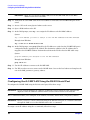
Replacing the Top Metal Cover . . . . . . . . . . . . . . . . . . . . . . . . . . . . . . . . . . . . . . . . . . . . . . . . . . . . . . .
Installing Internal Hard Disk Drives . . . . . . . . . . . . . . . . . . . . . . . . . . . . . . . . . . . . . . . . . . . . . . . . . . . .
Installing Additional System Memory . . . . . . . . . . . . . . . . . . . . . . . . . . . . . . . . . . . . . . . . . . . . . . . . . . .
Supported DIMM Sizes . . . . . . . . . . . . . . . . . . . . . . . . . . . . . . . . . . . . . . . . . . . . . . . . . . . . . . . . . . . . .
Installing System Memory . . . . . . . . . . . . . . . . . . . . . . . . . . . . . . . . . . . . . . . . . . . . . . . . . . . . . . . . . . .
Installing Additional PCI Cards . . . . . . . . . . . . . . . . . . . . . . . . . . . . . . . . . . . . . . . . . . . . . . . . . . . . . . . .
Removing the PCI Cage . . . . . . . . . . . . . . . . . . . . . . . . . . . . . . . . . . . . . . . . . . . . . . . . . . . . . . . . . . . . .
Installing PCI Cards. . . . . . . . . . . . . . . . . . . . . . . . . . . . . . . . . . . . . . . . . . . . . . . . . . . . . . . . . . . . . . . .
Installing an Additional Power Supply. . . . . . . . . . . . . . . . . . . . . . . . . . . . . . . . . . . . . . . . . . . . . . . . . . .
Installing an Additional Processor . . . . . . . . . . . . . . . . . . . . . . . . . . . . . . . . . . . . . . . . . . . . . . . . . . . . . .
36
37
40
40
41
43
44
46
47
49
4. Installing the Server into a Rack or Tower
Install the Server into a Rack . . . . . . . . . . . . . . . . . . . . . . . . . . . . . . . . . . . . . . . . . . . . . . . . . . . . . . . . . .
HP Rack. . . . . . . . . . . . . . . . . . . . . . . . . . . . . . . . . . . . . . . . . . . . . . . . . . . . . . . . . . . . . . . . . . . . . . . . . .
Non-HP Rack. . . . . . . . . . . . . . . . . . . . . . . . . . . . . . . . . . . . . . . . . . . . . . . . . . . . . . . . . . . . . . . . . . . . . .
Install the Server into a Tower Mount . . . . . . . . . . . . . . . . . . . . . . . . . . . . . . . . . . . . . . . . . . . . . . . . . . .
56
56
56
56
5. Connecting Cables
AC Input Power . . . . . . . . . . . . . . . . . . . . . . . . . . . . . . . . . . . . . . . . . . . . . . . . . . . . . . . . . . . . . . . . . . . . .
Power States . . . . . . . . . . . . . . . . . . . . . . . . . . . . . . . . . . . . . . . . . . . . . . . . . . . . . . . . . . . . . . . . . . . . . .
Apply Standby Power to the Server . . . . . . . . . . . . . . . . . . . . . . . . . . . . . . . . . . . . . . . . . . . . . . . . . . . .
Power Cord Retention. . . . . . . . . . . . . . . . . . . . . . . . . . . . . . . . . . . . . . . . . . . . . . . . . . . . . . . . . . . . . . .
LAN. . . . . . . . . . . . . . . . . . . . . . . . . . . . . . . . . . . . . . . . . . . . . . . . . . . . . . . . . . . . . . . . . . . . . . . . . . . . . . .
58
58
59
59
60
6. Console Connection and Setup
Setup Checklist . . . . . . . . . . . . . . . . . . . . . . . . . . . . . . . . . . . . . . . . . . . . . . . . . . . . . . . . . . . . . . . . . . . . .
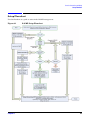
Setup Flowchart . . . . . . . . . . . . . . . . . . . . . . . . . . . . . . . . . . . . . . . . . . . . . . . . . . . . . . . . . . . . . . . . . . . . .
Preparation. . . . . . . . . . . . . . . . . . . . . . . . . . . . . . . . . . . . . . . . . . . . . . . . . . . . . . . . . . . . . . . . . . . . . . . . .
Determining the Physical iLO MP Access Method . . . . . . . . . . . . . . . . . . . . . . . . . . . . . . . . . . . . . . . .
Determining the iLO MP LAN Configuration Method . . . . . . . . . . . . . . . . . . . . . . . . . . . . . . . . . . . . .
Configuring the iLO MP LAN Using DHCP and DNS . . . . . . . . . . . . . . . . . . . . . . . . . . . . . . . . . . . . . .
Configuring the iLO MP LAN Using ARP Ping . . . . . . . . . . . . . . . . . . . . . . . . . . . . . . . . . . . . . . . . . . . .
Configuring the iLO MP LAN Using the RS-232 Serial Port . . . . . . . . . . . . . . . . . . . . . . . . . . . . . . . . .
Logging In to the iLO MP . . . . . . . . . . . . . . . . . . . . . . . . . . . . . . . . . . . . . . . . . . . . . . . . . . . . . . . . . . . . .
Additional Setup . . . . . . . . . . . . . . . . . . . . . . . . . . . . . . . . . . . . . . . . . . . . . . . . . . . . . . . . . . . . . . . . . . . .
Modifying User Accounts and Default Password . . . . . . . . . . . . . . . . . . . . . . . . . . . . . . . . . . . . . . . . .
Setting Up Security . . . . . . . . . . . . . . . . . . . . . . . . . . . . . . . . . . . . . . . . . . . . . . . . . . . . . . . . . . . . . . . .
62
63
64
64
65
66
67
68
70
70
70
71
7. Powering On the Server
Powering On the Server to Full Power . . . . . . . . . . . . . . . . . . . . . . . . . . . . . . . . . . . . . . . . . . . . . . . . . . . 74
Powering On the Server . . . . . . . . . . . . . . . . . . . . . . . . . . . . . . . . . . . . . . . . . . . . . . . . . . . . . . . . . . . . . 74
8. Accessing the Host Console
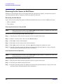
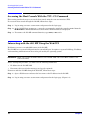
Accessing the Host Console With the TUI - CO Command . . . . . . . . . . . . . . . . . . . . . . . . . . . . . . . . . . . 76
Interacting with the iLO MP Using the Web GUI . . . . . . . . . . . . . . . . . . . . . . . . . . . . . . . . . . . . . . . . . . 76
4
Contents
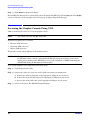
Accessing the Graphic Console Using VGA . . . . . . . . . . . . . . . . . . . . . . . . . . . . . . . . . . . . . . . . . . . . . . . 78
9. Booting the Operating System
Operating Systems Supported on HP Integrity Servers . . . . . . . . . . . . . . . . . . . . . . . . . . . . . . . . . . . . .
Configuring System Boot Options. . . . . . . . . . . . . . . . . . . . . . . . . . . . . . . . . . . . . . . . . . . . . . . . . . . . . . .
Booting and Shutting Down HP-UX . . . . . . . . . . . . . . . . . . . . . . . . . . . . . . . . . . . . . . . . . . . . . . . . . . . . .
Adding HP-UX to the Boot Options List . . . . . . . . . . . . . . . . . . . . . . . . . . . . . . . . . . . . . . . . . . . . . . . .
Standard HP-UX Booting . . . . . . . . . . . . . . . . . . . . . . . . . . . . . . . . . . . . . . . . . . . . . . . . . . . . . . . . . . . .
Single-User Mode HP-UX Booting. . . . . . . . . . . . . . . . . . . . . . . . . . . . . . . . . . . . . . . . . . . . . . . . . . . . .
LVM Maintenance Mode HP-UX Booting . . . . . . . . . . . . . . . . . . . . . . . . . . . . . . . . . . . . . . . . . . . . . . .
Shutting Down HP-UX . . . . . . . . . . . . . . . . . . . . . . . . . . . . . . . . . . . . . . . . . . . . . . . . . . . . . . . . . . . . . .
Booting and Shutting Down HP OpenVMS . . . . . . . . . . . . . . . . . . . . . . . . . . . . . . . . . . . . . . . . . . . . . . .
Adding HP OpenVMS to the Boot Options List . . . . . . . . . . . . . . . . . . . . . . . . . . . . . . . . . . . . . . . . . .
Booting HP OpenVMS . . . . . . . . . . . . . . . . . . . . . . . . . . . . . . . . . . . . . . . . . . . . . . . . . . . . . . . . . . . . . .
Shutting Down HP OpenVMS . . . . . . . . . . . . . . . . . . . . . . . . . . . . . . . . . . . . . . . . . . . . . . . . . . . . . . . .
Booting and Shutting Down Microsoft Windows . . . . . . . . . . . . . . . . . . . . . . . . . . . . . . . . . . . . . . . . . . .
Adding Microsoft Windows to the Boot Options List . . . . . . . . . . . . . . . . . . . . . . . . . . . . . . . . . . . . . .
Booting the Microsoft Windows Operating System . . . . . . . . . . . . . . . . . . . . . . . . . . . . . . . . . . . . . . .
Shutting Down Microsoft Windows . . . . . . . . . . . . . . . . . . . . . . . . . . . . . . . . . . . . . . . . . . . . . . . . . . . .
Booting and Shutting Down Linux . . . . . . . . . . . . . . . . . . . . . . . . . . . . . . . . . . . . . . . . . . . . . . . . . . . . . .
Adding Linux to the Boot Options List . . . . . . . . . . . . . . . . . . . . . . . . . . . . . . . . . . . . . . . . . . . . . . . . .
Booting the Red Hat Enterprise Linux Operating System . . . . . . . . . . . . . . . . . . . . . . . . . . . . . . . . .
Booting the SuSE Linux Enterprise Server Operating System . . . . . . . . . . . . . . . . . . . . . . . . . . . . . .
Shutting Down Linux . . . . . . . . . . . . . . . . . . . . . . . . . . . . . . . . . . . . . . . . . . . . . . . . . . . . . . . . . . . . . . .
80
80
82
82
83
85
86
87
88
88
89
91
92
92
93
94
95
96
97
98
99
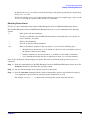
10. Troubleshooting
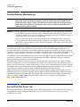
Troubleshooting Methodology . . . . . . . . . . . . . . . . . . . . . . . . . . . . . . . . . . . . . . . . . . . . . . . . . . . . . . . . .
Server Does Not Power On . . . . . . . . . . . . . . . . . . . . . . . . . . . . . . . . . . . . . . . . . . . . . . . . . . . . . . . . . . .
Server Does Not Power Off . . . . . . . . . . . . . . . . . . . . . . . . . . . . . . . . . . . . . . . . . . . . . . . . . . . . . . . . . . .
EFI Menu is Not Available . . . . . . . . . . . . . . . . . . . . . . . . . . . . . . . . . . . . . . . . . . . . . . . . . . . . . . . . . . .
Operating System Does Not Boot . . . . . . . . . . . . . . . . . . . . . . . . . . . . . . . . . . . . . . . . . . . . . . . . . . . . . .
Operating System Boots with Problems . . . . . . . . . . . . . . . . . . . . . . . . . . . . . . . . . . . . . . . . . . . . . . . . .
Intermittent Server Problems . . . . . . . . . . . . . . . . . . . . . . . . . . . . . . . . . . . . . . . . . . . . . . . . . . . . . . . . .
DVD Problems Occur . . . . . . . . . . . . . . . . . . . . . . . . . . . . . . . . . . . . . . . . . . . . . . . . . . . . . . . . . . . . . . . .
Hard Drive Problems Occur . . . . . . . . . . . . . . . . . . . . . . . . . . . . . . . . . . . . . . . . . . . . . . . . . . . . . . . . . .
Console Problems Occur . . . . . . . . . . . . . . . . . . . . . . . . . . . . . . . . . . . . . . . . . . . . . . . . . . . . . . . . . . . . .
Downloading and Installing the Latest Version of the Firmware . . . . . . . . . . . . . . . . . . . . . . . . . . . . .
Downloading the Latest Version of the Firmware . . . . . . . . . . . . . . . . . . . . . . . . . . . . . . . . . . . . . . .
Installing the Latest Version of the Firmware on the Server . . . . . . . . . . . . . . . . . . . . . . . . . . . . . .
102
102
103
104
104
104
105
105
105
106
106
106
106
Index . . . . . . . . . . . . . . . . . . . . . . . . . . . . . . . . . . . . . . . . . . . . . . . . . . . . . . . . . . . . . . . . . . . . . . 107
5
Contents
6
Tables
Table 1. Publishing History Details . . . . . . . . . . . . . . . . . . . . . . . . . . . . . . . . . . . . . . . . . . . . . . . . . . 11
Table 2. HP-UX 11i Releases . . . . . . . . . . . . . . . . . . . . . . . . . . . . . . . . . . . . . . . . . . . . . . . . . . . . . . . . 13
Table 1-1. Server Dimensions . . . . . . . . . . . . . . . . . . . . . . . . . . . . . . . . . . . . . . . . . . . . . . . . . . . . . . . 17
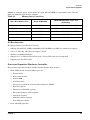
Table 1-2. Memory Array Capacities. . . . . . . . . . . . . . . . . . . . . . . . . . . . . . . . . . . . . . . . . . . . . . . . . . 23
Table 1-3. Installation Sequence Checklist. . . . . . . . . . . . . . . . . . . . . . . . . . . . . . . . . . . . . . . . . . . . . 28
Table 5-1. Power States . . . . . . . . . . . . . . . . . . . . . . . . . . . . . . . . . . . . . . . . . . . . . . . . . . . . . . . . . . . . 58
Table 6-1. Setup Checklist . . . . . . . . . . . . . . . . . . . . . . . . . . . . . . . . . . . . . . . . . . . . . . . . . . . . . . . . . . 62
Table 6-2. Console Connection Matrix . . . . . . . . . . . . . . . . . . . . . . . . . . . . . . . . . . . . . . . . . . . . . . . . 64
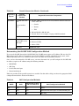
Table 6-3. LAN Configuration Methods . . . . . . . . . . . . . . . . . . . . . . . . . . . . . . . . . . . . . . . . . . . . . . . 65
Table 6-4. ARP Ping Commands . . . . . . . . . . . . . . . . . . . . . . . . . . . . . . . . . . . . . . . . . . . . . . . . . . . . . 67
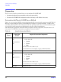
Table 10-1. Server Power Button Functions When Server is On and at EFI . . . . . . . . . . . . . . . . . 103
Table 10-2. Server Power Button Functions When Server is On and OS is Running . . . . . . . . . . 103
Table 10-3. Server Power Button Functions When Server is Off . . . . . . . . . . . . . . . . . . . . . . . . . . 104
7
Tables
8
Figures
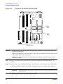
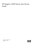
Figure 1-1. HP Integrity rx2620 Server (front view) . . . . . . . . . . . . . . . . . . . . . . . . . . . . . . . . . . . . .
Figure 1-2. HP Integrity rx2620 Server (front view with bezel removed) . . . . . . . . . . . . . . . . . . . .
Figure 1-3. HP Integrity rx2620 Server (rear view). . . . . . . . . . . . . . . . . . . . . . . . . . . . . . . . . . . . . .
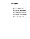
Figure 1-4. System Block Diagram . . . . . . . . . . . . . . . . . . . . . . . . . . . . . . . . . . . . . . . . . . . . . . . . . . .
Figure 1-5. Memory Block Diagram . . . . . . . . . . . . . . . . . . . . . . . . . . . . . . . . . . . . . . . . . . . . . . . . . .
Figure 3-1. Top Metal Cover Lock Location. . . . . . . . . . . . . . . . . . . . . . . . . . . . . . . . . . . . . . . . . . . .
Figure 3-2. Removing and Replacing the Top Metal Cover . . . . . . . . . . . . . . . . . . . . . . . . . . . . . . .
Figure 3-3. Aligning the Top Metal Cover . . . . . . . . . . . . . . . . . . . . . . . . . . . . . . . . . . . . . . . . . . . . .
Figure 3-4. Closing the Top Metal Cover . . . . . . . . . . . . . . . . . . . . . . . . . . . . . . . . . . . . . . . . . . . . . .
Figure 3-5. Front View of the HP Integrity rx2620 Server . . . . . . . . . . . . . . . . . . . . . . . . . . . . . . . .
Figure 3-6. Lock/Unlock Lever . . . . . . . . . . . . . . . . . . . . . . . . . . . . . . . . . . . . . . . . . . . . . . . . . . . . . .
Figure 3-7. Filler Removal from Slot . . . . . . . . . . . . . . . . . . . . . . . . . . . . . . . . . . . . . . . . . . . . . . . . .
Figure 3-8. Disk Drive Installation . . . . . . . . . . . . . . . . . . . . . . . . . . . . . . . . . . . . . . . . . . . . . . . . . .
Figure 3-9. DIMM Slot Identification . . . . . . . . . . . . . . . . . . . . . . . . . . . . . . . . . . . . . . . . . . . . . . . . .
Figure 3-10. Removing the Memory Airflow Guide. . . . . . . . . . . . . . . . . . . . . . . . . . . . . . . . . . . . . .
Figure 3-11. Inserting DIMM into Slot . . . . . . . . . . . . . . . . . . . . . . . . . . . . . . . . . . . . . . . . . . . . . . . .
Figure 3-12. Removing the PCI Cage. . . . . . . . . . . . . . . . . . . . . . . . . . . . . . . . . . . . . . . . . . . . . . . . .
Figure 3-13. Removing the PCI Cage Cover . . . . . . . . . . . . . . . . . . . . . . . . . . . . . . . . . . . . . . . . . . .
Figure 3-14. Installing a PCI Card. . . . . . . . . . . . . . . . . . . . . . . . . . . . . . . . . . . . . . . . . . . . . . . . . . .
Figure 3-15. Removing the Power Supply Filler Panel . . . . . . . . . . . . . . . . . . . . . . . . . . . . . . . . . . .
Figure 3-16. Replacing the Power Supply . . . . . . . . . . . . . . . . . . . . . . . . . . . . . . . . . . . . . . . . . . . . .
Figure 3-17. Processor Location . . . . . . . . . . . . . . . . . . . . . . . . . . . . . . . . . . . . . . . . . . . . . . . . . . . . .
Figure 3-18. Processor Location on System Board . . . . . . . . . . . . . . . . . . . . . . . . . . . . . . . . . . . . . . .
Figure 3-19. Removing the Processor Airflow Guide . . . . . . . . . . . . . . . . . . . . . . . . . . . . . . . . . . . .
Figure 3-20. Unlocking the Processor Module Locking Mechanism. . . . . . . . . . . . . . . . . . . . . . . . .
Figure 3-21. Alignment Pins on Processor. . . . . . . . . . . . . . . . . . . . . . . . . . . . . . . . . . . . . . . . . . . . .
Figure 3-22. Aligning the Processor . . . . . . . . . . . . . . . . . . . . . . . . . . . . . . . . . . . . . . . . . . . . . . . . . .
Figure 3-23. Locking the Processor Module in Place . . . . . . . . . . . . . . . . . . . . . . . . . . . . . . . . . . . .
Figure 3-24. Slide the Sequencing Retainer Plate . . . . . . . . . . . . . . . . . . . . . . . . . . . . . . . . . . . . . .
Figure 3-25. Secure the Captive Screws . . . . . . . . . . . . . . . . . . . . . . . . . . . . . . . . . . . . . . . . . . . . . .
Figure 5-1. Installing the Power Cord Retention Bracket . . . . . . . . . . . . . . . . . . . . . . . . . . . . . . . .
Figure 5-2. Power Retention Clip and Tie Wrap . . . . . . . . . . . . . . . . . . . . . . . . . . . . . . . . . . . . . . . .
Figure 5-3. Rear Panel LAN Ports. . . . . . . . . . . . . . . . . . . . . . . . . . . . . . . . . . . . . . . . . . . . . . . . . . . .
Figure 6-1. iLO MP Setup Flowchart . . . . . . . . . . . . . . . . . . . . . . . . . . . . . . . . . . . . . . . . . . . . . . . . .
Figure 8-1. Web Login Page . . . . . . . . . . . . . . . . . . . . . . . . . . . . . . . . . . . . . . . . . . . . . . . . . . . . . . . .
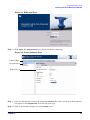
Figure 8-2. Status Summary Page . . . . . . . . . . . . . . . . . . . . . . . . . . . . . . . . . . . . . . . . . . . . . . . . . . .
16
16
16
20
22
35
35
36
36
37
38
38
39
41
42
43
45
45
47
48
48
49
50
51
51
52
52
53
53
54
59
60
60
63
77
77
9
Figures
10
About This Document
This document provides information and instructions on installing the HP Integrity rx2620 server into a
standard rack or tower configuration.
The document printing date and part number indicate the document’s current edition. The printing date
changes when a new edition is printed. Minor changes may be made at reprint without changing the printing
date. The document part number changes when extensive changes are made.
Document updates may be issued between editions to correct errors or document product changes. To ensure
that you receive the updated or new editions, you should subscribe to the appropriate product support service.
See your HP sales representative for details.
The latest version of this document can be found on line at http://www.docs.hp.com.
Intended Audience
This document is intended to provide technical product and support information for authorized service
providers, system administrators, and HP support personnel.
This document is not a tutorial.
New and Changed Information in This Edition
•
This document is being updated as part of upgrading the HP Integrity rx2620 server.
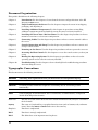
Publishing History
The publishing history below identifies the edition dates of this manual. Updates are made to this publication
on an unscheduled, as needed, basis. The updates will consist of a complete replacement manual and
pertinent on-line or CD documentation.
Table 1
Document
Manufacturing
Part Number
Publishing History Details
Operating Systems
Supported
Supported Product Versions
Publication Date
AB331-90002
HP-UX, Windows®,
Linux®
rx2620
September 2004
AB331-90005
HP-UX, Windows®,
Linux®, OpenVMS®
rx2620
June 2005
AD117-9001A
HP-UX, Windows®,
Linux®, OpenVMS®
rx2620
August 2006
11
Document Organization
This guide is divided into the following chapters.
Chapter 1
Introduction Use this chapter to learn about the features and specifications of the HP
Integrity rx2620 server.
Chapter 2
Unpack and Inspect the Server Use this chapter to inspect the server in its shipping
packaging, and unpacking it.
Chapter 3
Installing Additional Components Use this chapter fro procedures on installing
additional components purchased with the server that were not factory installed.
Chapter 4
Installing the Server into a Rack or Tower Use this chapter for procedures on how to
mount he server into a rack or tower configuration.
Chapter 5
Connecting Cables Use this chapter for procedures on how to connect external cables to
the server.
Chapter 6
Console Connection and Setup Use this chapter for procedures on how to connect and
set up a console session.
Chapter 7
Powering on the Server Use this chapter for procedures on how to power the server on.
Chapter 8
Accessing the Host Console Use this chapter to access the console session you have just
set up.
Chapter 9
Booting the Operating System Use this chapter for procedures on how to boot the
operating system on the server if not factory installed.
Chapter 10
Troubleshooting Use this chapter to learn about high-level troubleshooting procedures
when installing the server.
Typographic Conventions
This document uses the following conventions.
WARNING
A warning lists requirements that you must meet to avoid personal injury.
CAUTION
A caution provides information required to avoid losing data or avoid losing system
functionality.
NOTE
A note highlights useful information such as restrictions, recommendations, or important
details about HP product features.
Book Title
The title of a book. On the Web and on the Instant Information CD, it may be a hot link to
the book itself.
KeyCap
The name of a keyboard key or graphical interface item (such as buttons, tabs, and menu
items). Note that Return and Enter both refer to the same key.
Emphasis
Text that is emphasized.
Bold
Text that is strongly emphasized.
Bold
The defined use of an important word or phrase.
12
ComputerOut
Text displayed by the computer.
UserInput
Commands and other text that you type.
Command
A command name or qualified command phrase.
Option
An available option.
Screen Output Example of computer screen output.
[ ]
The contents are optional in formats and command descriptions. If the contents are a list
separated by |, you must select one of the items.
{ }
The contents are required in formats and command descriptions. If the contents are a list
separated by |, you must select one of the items.
...
The preceding element may be repeated an arbitrary number of times.
|
Separates items in a list of choices.
HP-UX Release Name and Release Identifier
Each HP-UX 11i release has an associated release name and release identifier. The uname (1) command with
the -r option returns the release identifier. This table shows the releases available for HP-UX 11i.
Table 2
HP-UX 11i Releases
Release Identifier
Release Name
Supported Processor Architecture
B.11.11
HP-UX 11i v1
PA-RISC
B.11.20
HP-UX 11i v1.5
Intel® Itanium®
B.11.22
HP-UX 11i v1.6
Intel Itanium
B.11.23
HP-UX 11i v2.0
Intel Itanium
Related Documents
You can find other information on HP server hardware management, Microsoft® Windows®, and diagnostic
support tools in the following publications.
Web Site for HP Technical Documentation:
http://docs.hp.com
Server Hardware Information:
http://docs.hp.com/hpux/hw/
Windows Operating System Information
You can find information about administration of the Microsoft Windows operating system at the following
Web sites, among others:
•
http://docs.hp.com/windows_nt/
•
http://www.microsoft.com/technet/
13
Diagnostics and Event Monitoring: Hardware Support Tools
Complete information about HP’s hardware support tools, including online and offline diagnostics and event
monitoring tools, is at the http://docs.hp.com/hpux/diag/ Web site. This site has manuals, tutorials,
FAQs, and other reference material.
Web Site for HP Technical Support:
http://us-support2.external.hp.com/
Books about HP-UX Published by Prentice Hall
The http://www.hp.com/hpbooks/ Web site lists the HP books that Prentice Hall currently publishes, such
as HP-UX books including:
•
HP-UX 11i System Administration Handbook
http://www.hp.com/hpbooks/prentice/ptr_0130600814.html
•
HP-UX Virtual Partitions
http://www.hp.com/hpbooks/prentice/ptr_0130352128.html
HP Books are available worldwide through bookstores, online booksellers, and office and computer stores.
HP Encourages Your Comments
HP encourages your comments concerning this document. We are truly committed to providing
documentation that meets your needs.
Please send comments to: [email protected].
Please include title, manufacturing part number, and any comment, error found, or suggestion for
improvement you have concerning this document. Also, please include what we did right so we can
incorporate it into other documents.
14
1 Introduction
The HP Integrity rx2620 server is a 2-socket server based on the Itanium processor architecture. The server
supports the following operating systems: Microsoft Windows, HP-UX, Linux, and OpenVMS. The server is
available in either rack-mount or tower configurations. The server accommodates up to 12 DIMMs and
internal peripherals, including disks and a DVD-ROM. Its high availability features include hot-swap power
supplies and hot-plug disk drives.
This chapter addresses the following topics:
•
“Server Overview” on page 16
•
“Server Components” on page 17
•
“System Board Components” on page 20
•
“Firmware” on page 26
•
“Safety Information” on page 27
•
“Installation Sequence and Checklist” on page 28
Chapter 1
15
Introduction
Server Overview
Server Overview
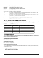
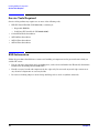
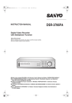
The HP Integrity rx2620 server chassis is a 2U Electronics Industry Association (EIA) enclosure, which
mounts in any standard 19 inch EIA rack. All external cabling connects through the rear of the enclosure.
With the server installed in the rack, service access is enhanced by the use of chassis slides. It has bays to
accommodate 1 + 1 redundant, hot-swappable power supplies, accessible from the front of the product. There
are 3 low-profile hot swappable hard disk drives accessible from the front, and a slim-line optical drive for a
CD-R, CD-RW, DVD-R or DVD+RW. There are N + 1 redundant, hot-swappable system fans, all clearly
identified and easily accessible. System status indication, a power switch, system locator switch and LED are
located in the front within the bezel. There is also a system locator switch and LED in the back of the system
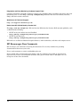
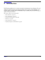
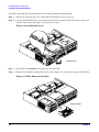
for easy identification in the rack. See Figure 1-1, Figure 1-2, and Figure 1-3 for front and back views of the
server.
Figure 1-1
HP Integrity rx2620 Server (front view)
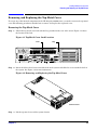
Figure 1-2
HP Integrity rx2620 Server (front view with bezel removed)
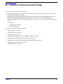
Figure 1-3
HP Integrity rx2620 Server (rear view)
WARNING Unplug all power cords from system before servicing
PWR
1
PWR
2
Management Card
CONSOLE
LAN 10/100
VGA
MP
CONSOLE / REMOTE / UPS
RESET
SERIAL A
Automatic Internal SCSI Termination
SCSI LVD/SE
16
LAN Gb A
LAN Gb B
TOC
USB
SERIAL B
Chapter 1
Introduction
Server Components
Server Dimensions
Table 1-1 shows the dimensions and weight of the rx2620 server.
Table 1-1
Server Dimensions
Dimensions
Value
Rack units
2U
Height
8.6 cm (3.4 in.)
Width
48.3 cm (19.0 in.)
Depth
67.9 cm (26.8 in.)
Weight
•
•
Min.
Max.
17.5 kg (38.6 lb.)
22.2 kg (49.0 lb.)
Server Components
The following components make up the HP Integrity rx2620 server:
•
“Itanium-2 Processors” on page 17
•
“Memory” on page 18
•
“PCI Riser” on page 18
•
“Internal Core I/O” on page 18
•
“External Core I/O” on page 18
•
“Power Supply Unit” on page 18
•
“System Board Manageability” on page 19
•
“Enhanced Server Manageability Using the Integrated Lights Out Management Processor” on page 19
•
“Hard Disk Drives” on page 19
The following sections contain details of the listed components.
Itanium-2 Processors
•
1.4 GHz/12 MB L3 cache dual-core processor
•
1.6 GHz/18 MB L3 cache dual-core processor
Chapter 1
17
Introduction
Server Components
Memory
•
12 memory DIMM slots
•
256 MB, 512 MB, 1 GB, 2 GB, and 4 GB standard 184 pins 2.5 V DDR1, CL2, registered, ECC
•
133 MHz memory bus frequency, 266 MTransfers/s data, 8.5 Gb/s peak data bandwidth
•
Minimum memory size of 1 GB with four 256 MB DIMMs
•
Maximum memory size of 32 GB with eight 4 GB DIMMs
•
Upgrades must be made by quads of DIMMs
•
DIMMs loaded by quads enable interleaved mode & chip spare
PCI Riser
•
Four independent PCI-X 133 MHz 64 bit, 3.3 V, 15 W slots. There is no 5 V card & hot plug support
NOTE
Some 25 W cards are supported. See the following slot matrix (by server):
http://www.docs.hp.com/en/SSM1-EL/slotmatrix.htm
For more information regarding specific I/O cards, see:
http://www.docs.hp.com/en/netcom.html
Internal Core I/O
•
Dual channel SCSI U320 interface, two internal 68 pin connectors, one 68 pin external connector
•
The three internal SCSI drive connectors are the 80 pin type and provide drive electrical hot-plug
capability
•
One internal IDE connector for a slim-line optical device (CD and DVD)
•
No floppy connector
External Core I/O
•
One SCSI U320 68 pin connector
•
Two 10/100/1000Base-T ethernet LAN connectors for twisted pair cable
•
Four USB 2.0 ports
•
Two general purpose 9 pin serial ports, 16550 compatible
Power Supply Unit
•
600 W output power
•
The power supply is split in a front-end block (the actual power supply case) that converts the line voltage
into a high DC voltage. Back-end voltage regulation modules (on the system board) step down the front
end DC voltage to the required voltages
•
Redundant and hot-pluggable power supplies (front-end block only)
18
Chapter 1
Introduction
Server Components
System Board Manageability
•
Baseboard Management Controller (BMC)
•
Temperature monitoring and fan regulation by BMC
•
BMC manageability console shared with system console and general purpose serial port
•
Intelligent platform management interface (IPMI) protocol for communication between
BMC/system/integrated lights out (iLO) manageability card
•
BMC hardware diagnostics display on the front status panel
•
Locator front and rear LEDs
•
Field replacement units monitoring by BMC
•
Serial port for local and modem console
•
Wake-on-LAN and Alert-on-LAN capabilities from the 10/100/1000 BT LAN port
Enhanced Server Manageability Using the Integrated Lights Out Management
Processor
The integrated Lights Out Management Processor (iLO MP) provides the ability to manage and monitor
many of the server’s processes and functions, including:
•
Web Graphical User Interface (GUI)
•
LAN telnet console
•
Web console
•
Serial port for local console
•
Serial port for modem console
•
Duplication of console screen content across all consoles
•
VGA and 2D graphics display
•
Advanced Features:
— Secure Shell (SSH) access
— Group actions through the HP Systems Insight Manager (HPSIM)
— Directory-based authentication and authorization (LDAP)
Hard Disk Drives
The following hard disk drives are supported by the rx2620 server:
•
36 GB 15K HotPlug Ultra320 SCSI drive
•
73 GB 15K HotPlug Ultra320 SCSI drive
•
146 GB 10K HotPlug Ultra320 SCSI drive
•
300 GB 10K HotPlug Ultra320 SCSI drive
The server holds up to three hard disk drives.
Chapter 1
19
Introduction
System Board Components
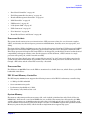
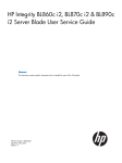
System Board Components
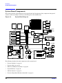
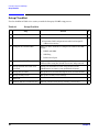
This section provides a block diagram of the system board and descriptions of key components (integrated
circuits) on the board. Figure 1-4 shows a block diagram of the rx2620 server.
Figure 1-4
System Block Diagram
Industry Standard DDR1 DIMM
DIMM
DIMM
FMW/PDC
Flash
816MB
MB
DIMM
DIMM
DIMM
FMW SRAM
MEMORY
Itanium-2
IPF
(on battery, scratch
RAM + NVM)
512KB
DIMM
Itanium-2
IPF
DIMM
DIMM
RTC
ASIC
Bus
Interface
DIMM
DIMM
DIMM
267MHz
8.5GB/S Peak Data BandWidth
200MHz
6.4GB/S Peak Data BandWidth
133 MHz bus clock
267 MT/s data rate
8.5GB/s peak data bandwidth
PCI-X Interface
ROPE 4
PCI-X 133 "Slot1"
ASIC
Bus
Interface
ASIC
Bus
Interface
ROPE 3
PCI-X 133 "Slot2"
ASIC
Bus
Interface
DMD
ROPE 5
PCI-X 133 "Slot3"
ROPE 2
PCI-X 133 "Slot4"
ASIC
Bus
Interface
ROPE 6
FPGA
LPC
LPC + ACPI
Bus
BMC
Manageability
Controller
COM2
Serial Port
OS Enabled
LED STATUS PANEL
I2C
etc...
LOCATOR
ON-OFF
DIAG LEDs
BMC SRAM 512KB
(on battery, scratch RAM•
+NVM+ FPL •
forward progress log)
BMC FLASH 1MB
LAN
Activity
BMC
bus
I2C, etc...
ROPE 7
System/BMC
Console
& Serial Port
PDH Bus
267MHz 8b data
533MB/s Peak Data
Bandwidth per rope
ASIC
Bus
Interface
COM1
DUART
ROPE 1
ASIC
Bus
Interface
PCI-X 133
ROPE 0
ASIC
Bus
Interface
VGA
Optional
FLASH
ASIC
Bus
Interface
LAN
LAN
10/100/
10/100/
1000
1G
PCI 33/32
PCI 33/32
VGA
FLASH
UPS
Battery•
SRAM
DRAM
Flash
etc...
iLO MP
RMC/GSP
Console
IDE
USB
2.0
SCSI ID 2
HDD #3
To AGP
Riser
Channel B
Channel A
Modem
Keyboard
Mouse
LAN100BT
Management Processor
DVD RW
Slim
Line
SCSI ID 1
HDD #2
SCSI ID 0
HDD #1
SCSI BACKPLANE
SCSI
U320
External
external
(se-lvds 68p)
(SE-LVDS SCA-2 80pin)
(SE-LVDS 68p)
The following describes the main components of the system board:
•
“Processor Sockets” on page 21
•
“Processor Bus” on page 21
•
“ZX1 I/O and Memory Controller” on page 21
•
“System Memory” on page 21
•
“I/O Bus Interface” on page 23
•
“Processor Dependent Hardware Controller” on page 23
20
Chapter 1
Introduction
System Board Components
•
“Dual Serial Controller” on page 24
•
“Field Programmable Gate Array” on page 24
•
“Baseboard Management Controller” on page 24
•
“SCSI Controller” on page 25
•
“IDE Interface” on page 25
•
“1 Gb System LAN” on page 25
•
“USB Connectors” on page 25
•
“User Interface” on page 26
•
“Event IDs for Errors and Events” on page 26
Processor Sockets
The system board consists of two zero insertion force (ZIF) processor sockets, the core electronic complex
(CEC), and circuitry for clock and power generation and distribution, boundary scan, in-target probe, and
debug.
The front side bus (FSB) is the IA64 processor bus, based on bus protocol from Intel. Unlike previous PA-RISC
microprocessors that utilized HP's proprietary processor bus, this processor is designed to utilize the FSB.
This allows processor field replaceable units (FRUs) to be dropped in, provided that electrical and mechanical
compatibility and support circuitry exist. For the purposes of this document, a FRU consists of a single
processor with power pod, and the heatsink assembly.
Each processor plugs directly into, and is powered by its own 12 V to 1.2 V power pod. Other power for the
system board comes from multiple on-board DC to DC converters. Each processor is attached to the board
through a ZIF socket and the entire FRU secured by a heatsink.
Processor Bus
The FSB runs at 200 MHz. Data on the FSB are transferred at a double data rate, which allows a peak FSB
bandwidth of 6.4 Gb/sec.
ZX1 I/O and Memory Controller
The HP Integrity rx2620 server supports the following features of the ZX1 I/O and memory controller chip:
•
8.5 Gb/s peak I/O bandwidth
•
Seven communication paths
•
Peak memory bandwidth of 8.5 Gb/s.
•
Two memory cells, 144 data bits each.
System Memory
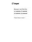
The memory subsystem provides two memory cells, each of which is 144 data bits wide. Each cell has six
DIMM slots, which means a total of 12 DIMM slots are available. The memory bus clock speed is 133 MHz,
and the data transfer rate is 266 Mtransfers/second as data is clocked on both edges of the clock. The peak
data bandwidth for this memory subsystem design is 8.5 Gb/s. Load DIMMs in quads with qualified modules.
Memory is protected by data ECC, and the hardware implementation supports chip-spare.
Chapter 1
21
Introduction
System Board Components
The minimum amount of memory supported by the server is 1 GB (four 256 MB modules). The maximum
amount of memory supported by the server is 32 GB (eight 4 GB modules).
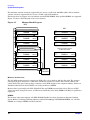
This design does not support any non industry standard DDR DIMMs. Only qualified DIMMs are supported.
Figure 1-5 shows a block diagram of the server memory.
Figure 1-5
Memory Block Diagram
MC0
Parallel Termination Resistors for Address and Control Rt=27 ohms
MC1
Parallel Termination Resistors for DQ[143:72] and associated DQS Rt=27 ohms
SA0=1
SA1=0
SA2=0
DIMM0B
CS1(0)
CS1(4)
SA0=1
SA1=0
SA2=0
DIMM1B
CS1(0)
CS1(4)
DIMM CLK Stub Isolation Resistors Rs=0 ohms
SA0=1
SA1=0
SA2=1
DIMM4B
CS1(2)
CS1(6)
SA0=1
SA1=0
SA2=1
DIMM5B
CS1(2)
CS1(6)
SA0=1
SA1=1
SA2=0
DIMM2B
CS1(1)
CS1(5)
SA0=1
SA1=1
SA2=0
DIMM3B
CS1(1)
CS1(5)
Stub Isolation Resistors for DQ[143:72] and associated DQS Rs=18 ohms
Same connection scheme
for MC1 as for MC0
DIMM CLK Stub Isolation Resistors Rs=0 ohms
Parallel Termination Resistors for DQ [71:0] and associated DQS Rt=27 ohms
SA0=0
SA1=0
SA2=0
DIMM0A
CS1(0)
CS1(4)
SA0=0
SA1=0
SA2=0
DIMM1A
CS1(0)
CS1(4)
SA0=0
SA1=0
SA2=1
DIMM4A
CS1(2)
CS1(6)
SA0=0
SA1=0
SA2=1
DIMM5A
CS1(2)
CS1(6)
SA0=0
SA1=1
SA2=0
DIMM3A
CS1(1)
CS1(5)
DIMM CLK Stub Isolation Resistors Rs=0 ohms
SA0=0
SA1=1
SA2=0
DIMM2A
CS1(1)
CS1(5)
Stub Isolation Resistors for DQ[71:0] and associated DQS Rs=18 ohms
Stub Isolation Resistors for Address and Control Rs=18 ohms
Memory
Controller
Memory Architecture
The I/O ASIC memory interface supports two DDR cells, each of which is 144 data bits wide. The memory
subsystem physical design uses a comb-filter termination scheme for both the data and the address and
control buses. This part of the topology is similar to other DDR designs in the computer industry. Clocks are
distributed directly from the I/O ASIC; each clock pair drives 2 DIMMs.
Memory data is protected by the ECC. Eight ECC bits per DIMM protect 64 bits of data. The use of ECC
allows correction of single-bit errors, and detection of multi-bit errors. Only DIMMs with ECC are qualified or
supported.
DIMMs
The memory subsystem supports only DDR SDRAM (Double Data Rate Synchronous Dynamic Random
Access Memory) technology utilizing industry-standard PC-1600 type DDR SDRAM DIMMs, 1.2" tall. The
DIMMs use a 184-pin JEDEC standard connector.
22
Chapter 1
Introduction
System Board Components
DIMMs are loaded in groups of four, known as a quad. All four DIMMs in a quad must be the same size.
Table 1-2 summarizes the memory solutions.
Table 1-2
Memory Array Capacities
Min / Max Memory Size
DDR SDRAM Count, Type and
Technology
Single DIMM Size
1 GB / 3 GB
256 MB DIMM
18 x 32 MB x 4 DDR1 SDRAMs (128 MB)
2 GB / 6 GB
512 MB DIMM
36 x 32 MB x 4 DDR1 SDRAMs (128 MB)
4 GB / 12 GB
1024 MB DIMM
36 x 64 MB x 4 DDR1 SDRAMs (256 MB)
8 GB / 24 GB
2048 MB DIMM
36 x 128 MB x 4 DDR1 SDRAMs (512 MB)
16 GB / 32 GB
4096 MB DIMM
36 x 256 MB x 4 DDR1 SDRAMs (1024 MB)
I/O Bus Interface
The I/O bus interface provides these features:
•
Industry standard PCI 33 MHz and 66 MHz, PCI-X 66 MHz to 133 MHz, 32 or 64 data bit support
•
Uses 3.3 V PCI only, and it does not support 5 V PCI
•
Optimizes for DMA performance
•
Supports 3.3 V or Universal keyed PCI cards. 5 V keyed PCI cards are not supported
•
Supports up to four PCI sockets
Processor Dependent Hardware Controller
The processor dependent hardware (PDH) controller provides these features:
•
16-bit PDH bus with reserved address space for:
— Flash memory
— Non-volatile memory
— Scratch RAM
— Real Time Clock
— Universal asynchronous receivers and transmitters (UARTs)
— External registers
— Firmware read/writable registers
— Two general purpose 32-bit registers
— Semaphore registers
— Monarch selection registers
— Test and Reset register
•
Reset and INIT generation
Chapter 1
23
Introduction
System Board Components
Dual Serial Controller
The dual serial controller is a dual universal asynchronous receiver and transmitter (DUART). This chip
provides enhanced UART functions with 16-byte first-in, first-out (FIFO) processing. Registers on this chip
provide onboard error indications and operation status. An internal loopback capability provides onboard
diagnostics.
Features include:
•
Data rates up to 115.2 kbps
•
16550A fully compatible controller
•
A 16-byte transmit FIFO to reduce the bandwidth requirement of the external CPU
•
A 16-byte receive FIFO with four selectable interrupt trigger levels and error flags to reduce the
bandwidth requirement of the external CPU
•
UART control that provides independent transmit and receive
•
Modem control signals (-CTS, -RTS, -DSR, -DTR, -RI, -CD, and software controllable line break)
•
Programmable character lengths (5, 6, 7, 8) with Even, Odd or No Parity
•
A status report register
Field Programmable Gate Array
The field programmable gate array (FPGA) provides ACPI and LPC support for the PDH bus and provides
these features:
•
ACPI 2.0 interface
•
LPC bus interface to support BMC
•
Decoding logic for PDH devices
Baseboard Management Controller
The baseboard management controller (BMC) supports the industry-standard IPMI specification. This
specification describes the management features that have been built into the system board. These features
include: local and remote diagnostics, console support, configuration management, hardware management,
and troubleshooting.
The BMC provides the following:
•
Compliance with IPMI 1.0
•
Tachometer inputs for fan speed monitoring
•
Pulse width modulator outputs for fan speed control
•
Push-button inputs for front panel buttons and switches
•
One serial port, multiplexed with the sever console port
•
Remote access and intelligent chassis management bus (ICMB) support
24
Chapter 1
Introduction
System Board Components
•
Three I2C primary and secondary ports (one port is used for the intelligent platform management bus
[IPMB])
•
Low pin count (LPC) bus provides access to three keyboard controller style (KCS), and one-block transfer
(BT) interface
•
32-bit ARM7 processor
•
160-pin low profile flat pack (LQFP) package
•
Firmware is provided for the following interfaces:
— IPMI
— IPMB
SCSI Controller
The SCSI controller is an LSI Logic 53C1030 chip. This chip is fully compliant with the SCSI Peripheral
Interface-3 Specification (SPI-3). It has two independent SCSI channels supporting devices at speeds up to
320 Mb/seconds each. The 53C1030 adheres to the PCI-X addendum to the PCI Local Specification and is
hard-wired to PCI ID 1 which corresponds to bit 17 of the PCI AD bus.
IDE Interface
The IDE controller (PCI649) supports the ATAPI zero to five modes (from 16 to 100 Mb/s). The usable speed
on this system is limited to 16 MHz (ATA-33 mode, 33 Mb/s) because the slimline CD/DVD devices do not
support the ATA-66 and 100 modes.
The primary IDE channel is the only channel that is implemented. The IDE cable provides only one drive
connector, of the Primary type, for the DVD peripheral.
1 Gb System LAN
The 1 Gb system LAN port provides:
•
Main system LAN
•
10/100/1000 Mb capability
USB Connectors
The USB connectors provide:
•
High speed 480 Mb/sec. capability
•
Full speed 12 Mb/second and low speed 1.5 Mb/second
•
Support for USB keyboard and mouse
•
HP-UX supports HP USB keyboard and mouse
Chapter 1
25
Introduction
Firmware
Firmware
Firmware consists of many individually linked binary images that are bound together by a single framework
at run time. Internally, the firmware employs a software database called a device tree to represent the
structure of the hardware platform and to provide a means of associating software elements with hardware
functionality.
The firmware incorporates the following main interfaces:
•
Processor Abstraction Layer (PAL). PAL provides a seamless firmware abstraction between the processor
and system software and platform firmware.
•
System Abstraction Layer (SAL). SAL provides a uniform firmware interface and initializes and
configures the platform.
•
Extensible Firmware Interface (EFI). EFI provides an interface between the operating system and the
platform firmware. EFI uses data tables that contain platform-related information, and boot and runtime
service calls that are available to the operating system and its loader to provide a standard environment
for booting.
•
Advanced Configuration and Power Interface (ACPI). ACPI provides a standard environment for
configuring and managing server systems. ACPI moves system power configuration and management
from the system firmware to the operating system and abstracts the interface between the platform
hardware and the operating system software. This allows each to evolve independently of the other.
The firmware supports the HP-UX 11i version 2, June 2006 release, Linux®, Windows®, and OpenVMS 8.3
operating systems through the Itanium processor family standards and extensions, and has no operating
system-specific functionality included. All operating systems are presented with the same interface to system
firmware, and all features are available to the operating system.
User Interface
The Itanium processor family firmware employs a user interface defined by an HP standard called Pre-OS
System Startup Environment (POSSE). The POSSE shell is based on the EFI standard shell. Several
commands were added to the standard EFI shell to support HP value-added functionality. Refer to the
POSSE specifications for further details.
Event IDs for Errors and Events
The system firmware generates event IDs for errors, events, and forward progress to the MP through common
shared memory. The MP interprets and stores event IDs. Reviewing these events helps you diagnose and
troubleshoot problems with the server.
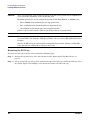
26
Chapter 1
Introduction
Safety Information
Safety Information
Use care to prevent injury and equipment damage when performing removal and replacement procedures.
Voltages can be present within the server. Many assemblies are sensitive to damage by electrostatic
discharge.
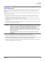
Follow the safety conventions listed below to ensure safe handling of components, to prevent injury, and to
prevent damage to the server:
•
When removing or installing any server component, follow the instructions provided in this guide.
•
If installing a hot-swappable or hot-pluggable component when power is applied (fans are running),
reinstall the server cover immediately to prevent overheating.
•
If installing a hot-pluggable component, complete the required software intervention prior to removing
the component.
•
If installing an assembly that is neither hot-swappable, nor hot-pluggable, disconnect the power cable
from the external server power receptacle.
WARNING
Ensure that the system is powered off and all power sources are disconnected
from the server prior to removing or installing server hardware unless you are
removing or installing a hot-swappable or hot-pluggable component.
Voltages are present at various locations within the server whenever an AC
power source is connected. This voltage is present even when the main power
switch is turned off.
Failure to observe this warning can result in personal injury or damage to
equipment.
•
Do not wear loose clothing that can snag or catch on the server or on other items.
•
Do not wear clothing subject to static charge buildup, such as wool or synthetic materials.
•
If installing an internal assembly, wear an antistatic wrist strap and use a grounding mat, such as those
included in the Electrically Conductive Field Service Grounding Kit (HP 9300-1155).
•
Handle accessory boards and components by the edges only. Do not touch any metal-edge connectors or
any electrical components on accessory boards.
Chapter 1
27
Introduction
Installation Sequence and Checklist
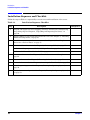
Installation Sequence and Checklist
Follow the steps in Table 1-3 sequentially to ensure successful installation of the server.
Table 1-3
Step
Installation Sequence Checklist
Description
1
Unpack and inspect the server shipping container; inventory the contents using
the packing slip. See Chapter 2, “Unpacking and Inspecting the Server,” on
page 29.
2
Install additional components shipped with the server. See Chapter 3, “Installing
Additional Components,” on page 33.
3
Install the server into a rack or tower mount. See Chapter 4, “Installing the
Server into a Rack or Tower,” on page 55.
4
Connect cables to the server. See Chapter 5, “Connecting Cables,” on page 57.
Completed
a: Connect AC input power cable. See “AC Input Power” on page 58.
b: Connect LAN core I/O cable. See “LAN” on page 60.
28
5
Start a console session. See Chapter 6, “Console Connection and Setup,” on
page 61.
6
Power on the server. See Chapter 7, “Powering On the Server,” on page 73.
7
Access the host console. See Chapter 8, “Accessing the Host Console,” on page 75.
8
Boot the operating system. See Chapter 9, “Booting the Operating System,” on
page 79.
9
Verify the server configuration. See Chapter 9, “Booting the Operating System,”
on page 79.
Chapter 1
2 Unpacking and Inspecting the Server
This chapter describes procedures performed before installation. Ensure that you have adequately prepared
your environment for your new server, received the components that you ordered, and verified that the server
and its containers are in good condition after shipment.
This chapter addresses the following topics:
•
“Verifying Site Preparation” on page 30.
•
“Inspecting the Shipping Containers for Damage” on page 30.
•
“Unpacking the Server” on page 30.
•
“Checking the Inventory” on page 31.
•
“Returning Damaged Equipment” on page 31.
•
“Unloading the Server with a Lifter” on page 31.
Chapter 2
29
Unpacking and Inspecting the Server
Verifying Site Preparation
Verifying Site Preparation
Verifying site preparation is an essential factor of a successful server installation, and includes the following
tasks:
•
Gather LAN information: Determine the two separate IP addresses for the MP LAN and the system LAN.
•
Establish a method to connect to the server console. For more information on console connection methods,
see Chapter 6, “Console Connection and Setup,” on page 61.
•
Verify electrical requirements: Ensure the grounding specifications and power requirements have been
met.
•
Validate server physical space requirements.
•
Confirm environmental requirements.
For more information on server electrical, physical space, and environmental requirements, refer to the HP
Integrity rx2620 Site Preparation Guide.
Inspecting the Shipping Containers for Damage
HP shipping containers protect their contents under normal shipping conditions. After the equipment arrives,
carefully inspect each carton for signs of shipping damage. Shipping damage constitutes moderate to severe
damage, such as punctures in the corrugated carton, crushed boxes, or large dents. Normal wear or slight
damage to the carton is not considered shipping damage. If you find shipping damage to the carton, contact
your HP customer service representative immediately.
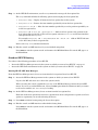
Unpacking the Server
The following procedure describes how to unpack a nonracked server.
Step 1. Use the instructions printed on the outside top flap of the carton; remove the banding and the outer
carton from the server pallet.
Step 2. Remove all inner accessory cartons and the top foam cushions, leaving only the server.
IMPORTANT Inspect each carton for shipping damage as you unpack the server.
30
Chapter 2
Unpacking and Inspecting the Server
Checking the Inventory
Checking the Inventory
The sales order packing slip lists all of the equipment shipped from HP. Use this packing slip to verify that all
of the equipment has arrived.
NOTE
To identify each item by part number, refer to the sales order packing slip.
Returning Damaged Equipment
If the equipment has any damage, you must immediately contact your HP customer service representative.
The service representative initiates appropriate action through the transport carrier or the factory and
assists you in returning the equipment.
Unloading the Server with a Lifter
To unload the server from the pallet using a lifter (if necessary), perform the following steps:
WARNING
Use caution when using a lifter. Because of the weight of the server, you must center
the server on the lifter forks before lifting it off the pallet to avoid injury.
NOTE
HP recommends that you follow your local guidelines when lifting equipment.
Step 1. Unpack the server.
Step 2. Unroll the bottom corrugated tray corresponding to the side on which the lifter will be placed and
slide the server as close to that edge of the pallet as possible.
Step 3. Break off any foam packaging which could prevent the lifter from being fully inserted under the
server. Do not remove the foam packaging from the corners of the server. This foam is required to
elevate the system and allow the forks of the lifter to be placed under the server.
Step 4. Insert the lifter forks under the server.
Step 5. Carefully roll the lift forward until it is fully positioned against the side of the server.
Step 6. Slowly raise the server off the pallet until it clears the pallet cushions.
Step 7. Carefully roll the lifter and server away from the pallet. Do not raise the server any higher than
necessary when moving it over to the rack.
NOTE
Chapter 2
HP recommends the use of a lifter, such as a RonI Company model 17000 SP 400 lifting device,
when moving a non-racked system.
31
Unpacking and Inspecting the Server
Checking the Inventory
32
Chapter 2
3 Installing Additional Components
This chapter provides information on the controls and indicators of the server and instructions required in
installing additional components and configuring the HP Integrity rx2620 server.
This chapter addresses the following topics:
•
“Service Tools Required” on page 34
•
“ESD Information” on page 34
•
“Installing Internal Hard Disk Drives” on page 37
•
“Installing Additional System Memory” on page 40
•
“Installing Additional PCI Cards” on page 43
•
“Installing PCI Cards” on page 46
•
“Installing an Additional Power Supply” on page 47
•
“Installing an Additional Processor” on page 49
Chapter 3
33
Installing Additional Components
Service Tools Required
Service Tools Required
Service of this product may require one or more of the following tools:
•
IPF CPU Install Tool Kit (P/N 5069-5441), consisting of:
— Disposable ESD Kit
— Label-less CPU install tool (P/N 09901-04007)
•
1/4 inch Flat Blade Screwdriver
•
ACX-10 Torx Screwdriver
•
ACX-15 Torx Screwdriver
•
ACX-25 Torx Screwdriver
ESD Information
Follow the procedures listed below to ensure safe handling of components and to prevent harm to both you
and the HP server:
•
Use an anti-static wrist strap and a grounding mat, such as those included in the Electrically Conductive
Field Service Grounding Kit (HP 9300-1155).
•
Handle accessory boards and components by the edges only. Do not touch any metal-edge connectors or
any electrical components on accessory boards.
•
Do not wear clothing subject to static charge build-up, such as wool or synthetic materials.
34
Chapter 3
Installing Additional Components
Removing and Replacing the Top Metal Cover
Removing and Replacing the Top Metal Cover
To access any of the internal components in the HP Integrity rx2620 server, you need to remove the top metal
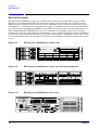
cover. The following procedures describe how to remove and replace the top metal cover.
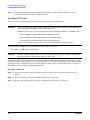
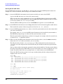
Removing the Top Metal Cover
Step 1. Unlock the top metal cover lock with the key provided on the rear of the server. Figure 3-1 shows
the location of the lock.
Figure 3-1 Top Metal Cover Lock Location
Key
Lock
WARNING Unplug all power cords from system before servicing
PWR
1
PWR
2
Management Card
CONSOLE
LAN 10/100
VGA
MP
CONSOLE / REMOTE / UPS
RESET
SERIAL A
Automatic Internal SCSI Termination
SCSI LVD/SE
LAN Gb A
LAN Gb B
TOC
USB
SERIAL B
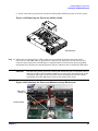
Step 2. Rotate the blue release lever toward the back of the system and slide the cover toward the back of
the system. See Figure 3-2 for more information.
Figure 3-2 Removing and Replacing the Top Metal Cover
Front of server
Step 3. Lift the top metal cover off the system chassis.
Chapter 3
35
Installing Additional Components
Removing and Replacing the Top Metal Cover
Replacing the Top Metal Cover
CAUTION
Secure any wires or cables in your server so they do not get cut or interfere with the
replacement of the top metal cover.
Step 1. Align the front edge of the top metal cover with the alignment mark on the optical drive bay. See
Figure 3-3 for more information.
Figure 3-3 Aligning the Top Metal Cover
To replace cover,
align front edge here
then slide forward
Front of server
Step 2. Grasp the blue release lever and slide the top metal cover toward the front of the system until the
lever snaps into place. See Figure 3-4 for more information.
Figure 3-4 Closing the Top Metal Cover
Front of server
Step 3. Lock the top metal cover and return the key to its stored position.
36
Chapter 3
Installing Additional Components
Installing Internal Hard Disk Drives
Installing Internal Hard Disk Drives
This section provides information about removing and replacing internal hard disk drives.
The HP Integrity rx2620 server supports up to three hot-pluggable, low-voltage differential (LVD) hard disk
drives. These hard disk drives are 3.5-inch form factor devices that connect to Ultra 320 Wide LVD SCSI
interfaces on the disk cage backplane. See Figure 3-5 for hard disk drive locations.
There is a significant difference between the terms hot-pluggable and hot-swappable:
•
Hot swapping happens at the device level. A hot-swappable device is removed and installed without
assistance from operating system commands.
•
Hot-plugging allows you to replace a defective disk drive in a high-availability system while it is running.
CAUTION
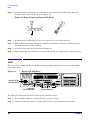
Figure 3-5
A hot-plug device may require interaction with the operating system before you install it into
the server. Verify that the operating system supports installing disk drives while the operating
system is running. If the operating system does not support this feature, shut down the
operating system before attempting this procedure. Failure to observe this caution results in
system failure.
Front View of the HP Integrity rx2620 Server
HDD 3
HDD 2
HDD 1
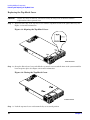
Two additional hard disk drive may be added to your HP server in slots 2 and 3. Always use low profile disk
drives (1.0” height) in your server. The drives may be locked in position by a toggle switch inside the server.
CAUTION
If you try to remove a hard disk drive without unlocking it from the system, you will damage
the hard drive bay.
NOTE
If the drive bay is not locked, you can install additional hard disk drives without removing the
server from the rack, and it is not necessary to remove the top metal cover. Completion of the
procedure does not require locking the disk bay, replacing the top metal cover, or replacing the
server in the rack. If the drive bay is not locked, go to step 4.
Chapter 3
37
Installing Additional Components
Installing Internal Hard Disk Drives
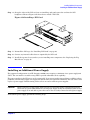
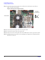
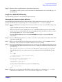
To install a hard disk drive when the drive bay is locked, perform the following steps:
Step 1. Remove the top metal cover. See “Removing the Top Metal Cover” on page 35.
Step 2. Locate the Lock/Unlock lever located between the drive bay and the side of the server at the front
left side of the server. See Figure 3-6 for the lever location.
Figure 3-6 Lock/Unlock Lever
Front of server
Step 3. Press down on the Unlock lever to disengage the drive lock.
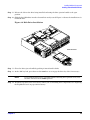
Step 4. Remove the slot filler by pulling it out of the server. Figure 3-7 shows how to remove the slot filler.
Figure 3-7 Filler Removal from Slot
Front of server
38
Chapter 3
Installing Additional Components
Installing Internal Hard Disk Drives
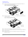
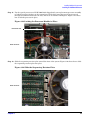
Step 5. Release the lock on the drive being installed and swing the drive ejection handle to the open
position.
Step 6. Slide the hard disk drive into the slot until it is nearly seated. Figure 3-8 shows the installation of a
hard disk drive.
Figure 3-8 Disk Drive Installation
Front of server
Step 7. Close the drive ejector handle by pushing it inward until it clicks.
Step 8. At the disk bay lock, press down on the Lock lever to re-engage the drive bay lock (if necessary).
NOTE
If you want the drives to be accessible without removing the top metal cover, leave
the drive lock lever in the Unlock position.
Step 9. Install the top metal cover (if necessary) unless you are installing more components. See “Replacing
the Top Metal Cover” on page 36 if necessary.
Chapter 3
39
Installing Additional Components
Installing Additional System Memory
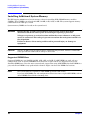
Installing Additional System Memory
The HP Integrity rx2620 server has 12 memory sockets for installing DDR SDRAM memory modules
(DIMMs). These DIMMs can either be 256 MB, 512 MB, 1 GB, 2 GB, or 4GB. The system supports memory
combinations from 1 GB up to 32 GB.
System memory DIMMs are located on the system board.
WARNING
Ensure that the system is powered down and all power sources have been
disconnected from the server prior to removing or replacing a processor.
Voltages are present at various locations within the server whenever an AC power
source is connected. This voltage is present even when the main power switch is in
the off position.
Failure to observe this warning could result in personal injury or damage to
equipment.
CAUTION
Observe all ESD safety precautions before attempting this procedure. Failure to follow ESD
safety precautions could result in damage to the server.
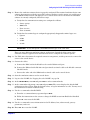
Supported DIMM Sizes
Supported DIMM sizes are 256 MB, 512 MB, 1 GB, 2 GB, and 4 GB. If 4 GB DIMMs are used, only two
configurations (four or eight 4 GB DIMMs in the first four or eight sockets) are supported. You can use
dissimilar DIMM sizes across the entire system board (except when using 4 GB DIMMs) but both DIMMs in a
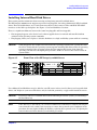
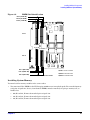
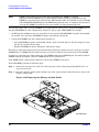
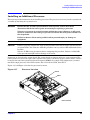
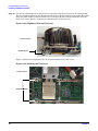
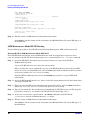
pair, and all four DIMMs of any quad must be identical. Figure 3-9 shows the DIMM slot locations.
NOTE
The system firmware required for 4 GB DIMM operation is 4.0 or later.
If you use 4 GB DIMMs, the only configurations allowed are four or eight 4 GB DIMMs, with no
other DIMMS allowed in the remaining slots.
40
Chapter 3
Installing Additional Components
Installing Additional System Memory
Figure 3-9
DIMM Slot Identification
Pair 4 (3A & 3B)
Pair 6 (5A & 5B)
Pair 2 (1A & 1B)
Cell 1
1A 3A 5A
1B 5B 3B
0B 4B 2B
0A 4A 2A
Cell 0
Pair 1 (0A & 0B)
Quad 1 = Pair 1 & Pair 2
Pair 5 (4A & 4B)
Pair 3 (2A & 2B)
Quad 2 = Pair 3 & Pair 4
Front of server
Quad 3 = Pair 5 & Pair 6
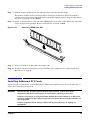
Installing System Memory
You must load the memory modules in the correct order:
•
You must install the DIMMs in the HP Integrity rx2620 server in matched quads. Two matched memory
card pairs of equal size (that is, four identical DIMMs) must be installed, one pair per memory cell, as
listed below:
•
0A, 0B and 1A, 1B must be matched pairs of equal size
•
2A, 2B and 3A, 3B must be matched pairs of equal size
•
4A, 4B and 5A, 5B must be matched pairs of equal size
Chapter 3
41
Installing Additional Components
Installing Additional System Memory
NOTE
DIMMs match if they have the same HP part number. The DIMMs are 184-pin,
industry-standard, DDR266, CL2, registered ECC modules. Industry standard means the
DIMMs meet specifications detailed in the JDEC Standard No. 21-C, Module 4, titled “PC2100
and PC1600 DDR SDRAM Registered DIMM Design Specification.” A complete and current list
of acceptable DIMMs is provided on the parts website at: http://partsurfer.hp.com.
You can mix module sizes, as long as DIMMs in each quad match, unless you are using 4 GB DIMMs. If you
install 4 GB DIMMS, the only configurations allowed are four or eight 4 GB DIMMs. For example:
•
On HP Integrity rx2620 servers, it is acceptable to load a quad of 256 MB DIMMs in quad 1 (slots 0A, 0B,
1A and 1B), and a quad of 1 GB DIMMs in quad 2 (slots 2A, 2B, 3A and 3B).
•
If using 4 GB DIMMs, the only configurations allowed are:
— Four 4 GB DIMMs in quad 1 (slots 0A, 0B, 1A, 1B), quad 2 (slots 2A, 2B, 3A, and 3B) and quad 3 (slots
4A, 4B, 5A, and 5B) remain empty
— Eight 4 GB DIMMs in quad 1 and quad 2, with quad 3 empty.
The memory subsystem supports chip-spare functionality. Chip spare enables the server to bypass an entire
SDRAM chip on a DIMM (logically replaced) in the event that a multi-bit error is detected on that SDRAM.
In order to use the chip spare functionality, use only DIMMs built with x4 SDRAM parts, You must load these
DIMMs in quads. See Figure 3-9 for the DIMM quads on the system board.
Each DIMM within a quad must be identical to all the other DIMMs in the quad.
To install DIMMs, perform the following steps:
Step 1. Remove the top metal cover if it is not already removed. See “Removing the Top Metal Cover” on
page 35 if necessary.
Step 2. Grasp the memory airflow guide and lift it out of the system. Figure 3-10 shows how to remove the
memory airflow guide.
Figure 3-10 Removing the Memory Airflow Guide
Front of server
42
Chapter 3
Installing Additional Components
Installing Additional PCI Cards
Step 3. Hold the memory module by the left and right edges and insert into the socket.
The memory modules are keyed and can only be inserted in one direction. When the module is
correctly seated, the retainer clips will return to their fully upright position. Snap the clips firmly
into place to properly seat the DIMMs.
Step 4. Gently and evenly push on each side of the DIMM until it seats in the socket. Ensure the extraction
levers are in the closed position. Figure 3-11 shows how to install a DIMM.
Figure 3-11
Inserting DIMM into Slot
Step 5. Replace the memory airflow guide. See Figure 3-10.
Step 6. Install the top metal cover, unless you are installing more components. See “Replacing the Top
Metal Cover” on page 36.
Installing Additional PCI Cards
Accessory cards are installed in a removable PCI cage. This section explains how to access the PCI cage, as
well as how to install accessory cards.
WARNING
Ensure that the system is powered down and all power sources have been
disconnected from the server prior to removing or replacing a processor.
Voltages are present at various locations within the server whenever an AC power
source is connected. This voltage is present even when the main power switch is in
the off position.
Failure to observe this warning could result in personal injury or damage to
equipment.
Chapter 3
43
Installing Additional Components
Installing Additional PCI Cards
CAUTION
There are restrictions on the number of PCI-X cards that can be installed in the rx2620 server
at any given time, depending on the cards being used.
Maximum quantity for any I/O configuration using 337972-B21, AB287A, or A9890A cards:
•
Three A9890A cards maximum plus one unpopulated slot
•
Two 337972-B21 cards maximum plus two unpopulated slots
•
One AB287A card maximum plus three unpopulated slots
Failure to observe this caution results in system degradation, or system failure.
CAUTION
Failure to properly complete the steps in this procedure will result in erratic system behavior
or system failure. For assistance with this procedure contact your local HP Authorized Service
Provider.
Observe all ESD safety precautions before attempting this procedure. Failure to follow ESD
safety precautions could result in damage to the server.
Removing the PCI Cage
To remove the PCI cage from the server, perform the following steps:
Step 1. Remove the top metal cover if not already removed See “Removing the Top Metal Cover” on
page 35.
Step 2. Lift up on the PCI cage release lever and the back edge of the PCI cage and lift the PCI cage out of
the system. Figure 3-12 and Figure 3-13 show how to remove the PCI card cage.
44
Chapter 3
Installing Additional Components
Installing Additional PCI Cards
Figure 3-12 Removing the PCI Cage
Front of server
Step 3. Grasp the PCI cage cover and slide it away from the bulkhead end of the cage, then lift the cover off.
Figure 3-13 Removing the PCI Cage Cover
Chapter 3
45
Installing Additional Components
Installing Additional PCI Cards
Step 4. Unscrew the bulkhead screw that holds the accessory card in place. The PCI slots are now
accessible for the installation of additional cards.
Installing PCI Cards
The server may contain up to four PCI cards. PCI cards are located in the PCI cage.
CAUTION
There are restrictions on the number of PCI-X cards that can be installed in the rx2620 server
at any given time, depending on the cards being used.
Maximum quantity for any I/O configuration using 337972-B21, AB287A, or A9890A cards:
•
Three A9890A cards maximum plus one unpopulated slot
•
Two 337972-B21 cards maximum plus two unpopulated slots
•
One AB287A card maximum plus three unpopulated slots
Failure to observe this caution will result in system degradation or system failure.
The HP Integrity rx2620 server has the following accessory card sockets:
•
Four 64-bit, 133 MHz PCI-X card sockets
CAUTION
Observe all ESD safety precautions before attempting this procedure. Failure to follow ESD
safety precautions could result in damage to the server.
Carefully read the following information concerning PCI slot configuration. Inserting a PCI card into a slot
that is not configured to accept it may cause operation failure or the PCI card to operate at less than optimum
speed. PCI slots are numbered 1 (top of cage) through 4 (bottom of cage). See the labels on the rear panel of
the chassis for correct PCI slot number identification.
Installing a PCI Card
Step 1. Remove the top metal cover if not already removed. See “Removing the Top Metal Cover” on
page 35.
Step 2. Remove the PCI cage. See “Removing the PCI Cage” on page 44.
Step 3. Remove and open the PCI cage. Refer to “Removing the PCI Cage” on page 44.
46
Chapter 3
Installing Additional Components
Installing an Additional Power Supply
Step 4. Grasp the edges of the PCI card you are installing, and gently press the card into the PCI
backplane connector. Figure 3-14 shows how to install a PCI card.
Figure 3-14 Installing a PCI Card
Step 5. Reinstall the PCI cage. See “Installing PCI Cards” on page 46.
Step 6. Connect any internal cables that are required by the PCI card.
Step 7. Install the top metal cover, unless you are installing more components. See “Replacing the Top
Metal Cover” on page 36.
Installing an Additional Power Supply
The supported configuration of an HP Integrity rx2620 server requires a minimum of one power supply unit
(PSU). You can install a second hot-swap PSU to provide redundant (N+1) capability.
The power supplies in the HP server are hot-swappable. If one power supply stops working or exhibits voltage
problems, the remaining supply can support the system until you replace the failed unit. You can remove and
replace a power supply without turning off the server on servers with two power supplies.
CAUTION
Before removing a power supply, make sure the second power supply is functioning properly.
Check the two green LEDs inside the second power supply. If they are illuminated, the second
power supply is on and able to power the server. You can safely remove the failed power supply.
To install the power supply, perform the following steps:
Chapter 3
47
Installing Additional Components
Installing an Additional Power Supply
Step 1. Remove the front bezel from the system and remove the power supply filler panel. Figure 3-15
shows how to remove the power supply filler panel.
Figure 3-15 Removing the Power Supply Filler Panel
Power supply 1
Front of server
Step 2. Open the power supply release lever and slide the power supply into place. Figure 3-16 shows how
to install a power supply.
Figure 3-16 Replacing the Power Supply
Power supply 2
Front of server
Power supply 1
Step 3. Push in on the power supply release lever to lock the retaining clip in place.
Step 4. Verify that both power supply LEDs, visible through the front of the power supply, are illuminated.
Step 5. Replace the front bezel.
Step 6. Install the top metal cover, unless you are installing more components. See “Replacing the Top
Metal Cover” on page 36.
48
Chapter 3
Installing Additional Components
Installing an Additional Processor
Installing an Additional Processor
This section provides information about installing processors. The processors are located on the system board,
accessible by removing the top metal cover.
WARNING
Ensure that the system is powered down and all power sources have been
disconnected from the server prior to removing or replacing a processor.
Voltages are present at various locations within the server whenever an AC power
source is connected. This voltage is present even when the main power switch is in
the off position.
Failure to observe this warning could result in personal injury or damage to
equipment.
CAUTION
Failure to properly complete the steps in this procedure will result in erratic system behavior
or system failure. For assistance with this procedure contact your local HP Authorized Service
Provider.
Observe all ESD safety precautions before attempting this procedure. Failure to follow ESD
safety precautions might result in damage to the server.
Processors are located on the system board. The system board can support either one or two processor. The
CPU 0 socket is located to the right of the system board (closer to the server chassis) and the CPU 1 socket is
located on the left of the system board near the memory DIMMs. In a single CPU configuration, you must
install the single processor in the CPU 0 socket. The load order is CPU 0, then CPU 1.
Figure 3-17 and Figure 3-18 show the processor locations).
Figure 3-17
Processor Location
CPU 0
CPU 1
Front of server
Chapter 3
49
Installing Additional Components
Installing an Additional Processor
Figure 3-18
Processor Location on System Board
CPU 0
slot
CPU 1
slot
Front of server
CAUTION
Ensure that the cache size is identical for all processors. Failure to observe this caution will
result in system failure.
Ensure that all processors are rated for use at the same speed. Failure to observe this caution
will result in performance degradation.
Valid processors are identified in the Parts Information chapter of the HP Integrity rx2620
Maintenance Guide.
Step 7. Remove the top metal cover if not already removed. See “Removing the Top Metal Cover” on
page 35.
Step 8. Remove the processor airflow guide. Figure 3-19 shows how to remove the processor airflow guide.
a. Remove the IDE cable and power module cables from the processor airflow guide cable clips.
CAUTION
Record the cable routing of these cables to ensure the cables are returned to their
correct routes.
b. Hold the guide using the opening on top of the guide.
50
Chapter 3
Installing Additional Components
Installing an Additional Processor
c. At the same time, grasp the back end of the airflow guide and lift the guide out of the system.
Figure 3-19 Removing the Processor Airflow Guide
Front of server
Step 9. Unlock the zero insertion force (ZIF) socket processor locking mechanism using the special
processor tool (P/N 5069-5441) or equivalent 2.5 mm hex tool. Insert the tool into the lock and
rotate the special processor tool 180 degrees counterclockwise. Verify that the processor-locking
mechanism is rotated into the unlocked position. Figure 3-20 shows how to unlock the ZIF socket.
CAUTION
The ZIF socket for the processor is locked and unlocked by 1/2 of a full turn of the 2.5
mm hex tool. The counterclockwise 180 degree rotation (1/2 turn) unlocks the socket.
A clockwise 180 degree rotation locks the socket. Attempting to turn the locking
mechanism more that 180 degrees will severely damage the socket.
Figure 3-20 Unlocking the Processor Module Locking Mechanism
CPU 1 slot
(empty)
Front of server
Chapter 3
51
Installing Additional Components
Installing an Additional Processor
Step 10. Use the two alignment pins on the processor to properly align the processor on the system board.
The two alignment pins fit in the alignment holes on the system board processor mount. The turbo
fan power cable must be positioned so that it is located on the side of the heatsink that faces the
front of the server. Figure 3-21 shows the alignment pins on the processor.
Figure 3-21 Alignment Pins on Processor
Front of server
Alignment pins
Figure 3-22 shows the alignment holes on the system board for the CPU 1 slot.
Figure 3-22 Aligning the Processor
Front of server
Alignment holes
52
Chapter 3
Installing Additional Components
Installing an Additional Processor
Step 11. Use the special processor tool (P/N 5069-5441) shipped with your replacement processor assembly
to lock the processor in place on the system board. To do this, insert the special processor tool
through the turbofan blades into the lock, and rotate it clockwise 180 degrees. Figure 3-23 shows
how to lock the processor in place.
Figure 3-23 Locking the Processor Module in Place
Processor tool
Front of server
Step 12. Slide the sequencing retainer plate toward the front of the system. Figure 3-24 shows how to slide
the sequencing retainer plate into place.
Figure 3-24 Slide the Sequencing Retainer Plate
Front of server
Chapter 3
53
Installing Additional Components
Installing an Additional Processor
Step 13. Screw in the four processor captive screws, and the two heat sink captive screws. Refer to
Figure 3-25 for the screw locations.
Figure 3-25 Secure the Captive Screws
Processor
torquing pattern
3
1
3
Front of server
1
5
2
2
4
4
6
Step 14. Connect the processor power cable to the server power cable.
Step 15. Connect the fan power cable to the system board.
Step 16. Replace the processor airflow guide, and route the IDE and power cables as previously recorded.
Step 17. Install the top metal cover, unless you are installing more components. See “Replacing the Top
Metal Cover” on page 36.
54
Chapter 3
4 Installing the Server into a Rack or Tower
This chapter provides instructions on how to install the server into a rack or a tower mount configuration.
The following sections are included in this chapter:
•
“Install the Server into a Rack” on page 56
•
“Install the Server into a Tower Mount” on page 56
Chapter 4
55
Installing the Server into a Rack or Tower
Install the Server into a Rack
Install the Server into a Rack
The following information describes how to install the server into an HP rack, or an approved non-HP rack.
HP Rack
HP Integrity entry-class servers that are installed into racks are shipped with equipment mounting slides.
With each set of slides comes an installation guide: Installation Guide, Mid-Weight Slide Kit, 5065-7291.
Follow the steps in this installation guide to determine where and how to place the server into the rack.
Non-HP Rack
There is a guide for evaluating the installation of HP equipment in non-HP racks. Use this document when
you need to qualify whether you can install, maintain, and service any HP equipment in a non-HP rack.
The guide is located on the Web at http://www.hp.com/racksolutions.
Once there, select “Mounting information” from the menu, then select the guide titled Mounting in non-HP
racks.
Install the Server into a Tower Mount
Your server ships with a tower mount if you order the rackless configuration option. The tower mount is
packaged in a separate carton that is attached to the server carton.
If you want to change your server from a rack mount to a rackless configuration, you need a Server Rackless
Mount Kit. Your rackless mount kit comes with an installation guide: Converting Your Rack Server to a
Rackless Mount. Follow the steps in this installation guide to attach the tower mount to your server.
56
Chapter 4
5 Connecting Cables
This chapter describes the cables that you must connect to install the server.
This chapter addresses the following topics:
•
“AC Input Power” on page 58
•
“LAN” on page 60
Chapter 5
57
Connecting Cables
AC Input Power
AC Input Power
The server can receive AC input from two different AC power sources. If two separate power sources are
available, you can plug the server into the separate power sources, increasing system reliability should one
power source fail. The power receptacles are located at the rear of the chassis. They are labeled PWR 1 and
PWR 2.
CAUTION
Do not route data and power cables in parallel paths in close proximity to each other. The
suggested minimum distance that the data and power cables should be apart is 7.62 cm (3
inches).
The power cord has current flowing through it, which creates a magnetic field. The potential to
induce electromagnetic interference in the data cables exists, thereby causing data corruption.
You can install a maximum of two bulk power supplies (BPS) in the server. Installing two BPSs in the server
provides n+1 redundancy, meaning that if one BPS fails, there is another power supply to power the server.
You must promptly replace the failed BPS to restore n+1 functionality.
A minimum of one BPS is required to power the server. There is no n+1 capability in this case.
Power States
The server has three power states:
•
Standby power
•
Full power
•
Off
Plug the power cord into the appropriate receptacle on the rear of the chassis to achieve the standby power
state; the front panel power button is not turned on. Full power occurs when the power cord is plugged into
the appropriate receptacle, and either the power is activated through the MP PC command, or the power
button is activated. In the off state, the power cords are not plugged in. Table 5-1 lists the server power states.
Table 5-1
Power States
Power States
Power Cable
Plugged Into
Receptacle?
Power Activated through the
MP PC Command; or
Front Panel Power Button
Activated?
AC Voltage
Applied?
DC Voltage
Applied?
Standby power
Yes
No
Yes
No
Full power
Yes
Yes
Yes
Yes
Off
No
No
No
No
NOTE
58
If the power restore feature is set to Always On through the MP PR command, the server may
automatically power on to the full power state.
Chapter 5
Connecting Cables
AC Input Power
Apply Standby Power to the Server
Perform the following steps to apply standby power to the server:
IMPORTANT If the server has one BPS, you must plug the power cable into the receptacle labeled PWR 1.
Step 1. Locate the appropriate receptacle on the rear of the chassis and plug the power cord into the
receptacle.
Step 2. Observe the following LEDs at two different intervals to ensure the server is in the standby power
state:
Interval One
After you plug the power cord into the server, the bulk power supplies flash
amber and an amber light is present on the hard disk drives.
Interval Two
Approximately 30 seconds later, the bulk power supplies flash green and the
amber light is still present on the hard disk drives. Standby power is on at this
point.
Power Cord Retention
The following procedure shows how to install the power cord retention clip onto the back of the server.
Step 1. Unscrew the two #3 screws on the server AC area. See Figure 5-1 for the screw locations.
Figure 5-1 Installing the Power Cord Retention Bracket
#3 screws
Chapter 5
59
Connecting Cables
LAN
Step 2. Install the plastic clip through the rectangular slot on the power retention bracket, and pull it
through until the clip clicks into place. See Figure 5-2.
Figure 5-2 Power Retention Clip and Tie Wrap
Step 3. Install the power cord bracket onto the server using the screws you just removed.
Step 4. Take the AC cord tie wrap and wrap it around the circumference of the AC cord and through the
hole in the tie wrap, near the connector.
Step 5. Insert the tie wrap into the plastic clip. See Figure 5-2.
Step 6. Repeat steps 2 through 5 (skip step 3) to secure the second power supply power cord (if necessary).
LAN
The server has two LAN ports that can provide network connectivity. Figure 5-3 shows the available LAN
ports for the server.
Figure 5-3
Rear Panel LAN Ports
WARNING Unplug all power cords from system before servicing
PWR
1
PWR
2
Management Card
iLO MP 10/100
LAN (optional)
CONSOLE
LAN 10/100
VGA
MP
CONSOLE / REMOTE / UPS
RESET
SERIAL A
Automatic Internal SCSI Termination
SCSI LVD/SE
LAN Gb A
LAN Gb A
10/100/1000 LAN
LAN Gb B
TOC
USB
SERIAL B
LAN Gb B
10/100/1000 LAN
To enable general network connectivity for the server, follow these steps:
Step 1. Obtain valid IP addresses for each LAN port you plan to activate.
Step 2. Connect the LAN cable from an available LAN port into a live connection on the network.
60
Chapter 5
6 Console Connection and Setup
Setting up the console involves the following:
•
Determining the physical access method to connect cables. There are two physical connections to the
Integrity iLO MP: RS-232 and LAN.
•
Configuring the Integrity iLO MP and assigning an IP address if necessary. Though there are several
methods to configuring the LAN, DHCP with DNS is the preferred one. DHCP with DNS comes
preconfigured with default factory settings, including a default user account and password. Other options
include:
— ARP-Ping
— Local RS-232 serial port
— Remote/modem port
This chapter addresses the following topics:
•
“Setup Checklist” on page 62
•
“Setup Flowchart” on page 63
•
“Preparation” on page 64
•
“Configuring the iLO MP LAN Using DHCP and DNS” on page 66
•
“Configuring the iLO MP LAN Using ARP Ping” on page 67
•
“Configuring the iLO MP LAN Using the RS-232 Serial Port” on page 68
•
“Logging In to the iLO MP” on page 70
•
“Additional Setup” on page 70
Chapter 6
61
Console Connection and Setup
Setup Checklist
Setup Checklist
Use the checklist in Table 6-1 to assist you with the Integrity iLO MP setup process.
Table 6-1
Setup Checklist
Step
Action
X
Standard and Advanced
1
Preparation
1. Determine access method to select and connect cables.
2. Determine LAN configuration method and assign IP
address if necessary.
2
Configure the iLO MP LAN
There are three methods to configure the LAN for iLO MP
access:
•
DHCP with DNS
•
ARP Ping
•
RS-232 serial port
3
Log on to the iLO MP
Log in to the iLO MP from a supported Web browser or
command line using the default user name and password.
4
Change default user name and
password
Change the default user name and password on the
administrator account to your predefined selections.
5
Set up user accounts
Set up the user accounts if using the local accounts feature.
6
Set up security access
Set up the security access settings.
Advanced
Activate Advanced Pack Features
62
Activate advanced features by entering a license key.
Chapter 6
Console Connection and Setup
Setup Flowchart
Setup Flowchart
Use this flowchart as a guide to assist in the iLO MP setup process.
Figure 6-1
Chapter 6
iLO MP Setup Flowchart
63
Console Connection and Setup
Preparation
Preparation
There are several tasks to perform before you can configure the iLO MP LAN.
•
Determine the physical access method to select and connect cables.
•
Determine the iLO MP LAN configuration method and assign an IP address if necessary.
Determining the Physical iLO MP Access Method
Before you can access the iLO MP, you must first determine the correct physical connection method. The iLO
MP has a separate LAN port from the system LAN port. It requires a separate LAN drop, IP address, and
networking information from that of the port used by the operating system. See your server installation guide
for rear panel console connection port identification and cable connection information.
Table 6-2 lists the appropriate connection method, required connection components, and connectors to the
host console. Use Table 6-2 to determine your physical connection method.
Table 6-2
Operating
System
HP-UX
Console Connection Matrix
Console
Connection
Method
Required Connection Components
Local RS-232 serial
port
1. M-cable: DB25 connector on one end, and three DB-9F connectors
on the other end:
Remote/modem
port
•
Console
•
Remote
•
UPS
2. RS-232 DB-9F to DB-9F cable
3. Console device (for example, a laptop or ASCII terminal)
LAN port
Linux
Local RS-232 serial
port
Remote/modem
port
10/100 LAN cable
1. M-cable: DB25 connector on one end, and three DB-9F connectors
on the other end:
•
Console
•
Remote
•
UPS
2. RS-232 DB-9F to DB-9F cable
3. Console device (for example, a laptop or ASCII terminal)
LAN port
64
10/100 LAN cable
Chapter 6
Console Connection and Setup
Preparation
Table 6-2
Console Connection Matrix (Continued)
Console
Connection
Method
Required Connection Components
Local RS-232 serial
port
1. M-cable: DB25 connector on one end, and three DB-9F connectors
on the other end:
Operating
System
OpenVMS
Remote/modem
port
•
Console
•
Remote
•
UPS
2. RS-232 DB-9F to DB-9F cable
3. Console device (for example, a laptop or ASCII terminal)
LAN Port
Windows
10/100 LAN cable
VGA Port
(no iLO MP access;
EFI only)
1. Monitor (VGA)
2. Keyboard (USB)
3. Mouse (USB)
LAN port
10/100 LAN cable
Determining the iLO MP LAN Configuration Method
To access the iLO MP through the iLO MP LAN, the iLO MP must acquire an IP address. The way the iLO
MP acquires an IP address is dependent upon whether DHCP is enabled or disabled on the server, and if
DHCP and DNS services are available to the server. (See Table 6-3 for possible scenarios.)
Once you have determined the iLO MP access, you must determine how you will configure the iLO MP LAN
in order to acquire an IP address using the following methods:
•
DHCP/DNS
•
ARP Ping
•
Local S-232 serial port
•
Remote/modem port
Table 6-3 provides all the possible scenarios to consider. Use this table to help you select the appropriate LAN
configuration method to obtain an IP address.
Table 6-3
LAN Configuration Methods
DHCP
DNS
RS-232 Serial Port
(MP LC command)
LAN Configuration Method
Yes
Yes
No
DHCP
Yes
Yes
Yes
DHCP, RS-232 serial port, or remote/modem port
No
No
No
ARP Ping
Chapter 6
65
Console Connection and Setup
Configuring the iLO MP LAN Using DHCP and DNS
Table 6-3
LAN Configuration Methods (Continued)
DHCP
DNS
RS-232 Serial Port
(MP LC command)
LAN Configuration Method
No
Yes
No
ARP Ping
No
Yes
Yes
ARP Ping, RS-232 serial port, or remote/modem
port
Yes
No
Yes
RS-232 serial port, or remote/modem port
No
No
Yes
RS-232 serial port, remote/modem port, or ARP
Ping
Yes
No
No
Cannot set up the LAN. Reconsider your criteria.
Once you have determined how you will configure the iLO MP LAN in order to acquire an IP address, you
must configure the iLO MP LAN using the selected method.
Configuring the iLO MP LAN Using DHCP and DNS
DHCP automatically configures all DHCP-enabled servers with IP addresses, subnet masks, and gateway
addresses. All HP Integrity entry class servers with the iLO MP are shipped from the factory with DHCP
enabled.
HP recommends using the DHCP and DNS method to simplify access to the iLO MP.
When you use DHCP and DNS, you can connect to the iLO MP by typing the default host name in your
browser rather than an IP address only if the following applies:
•
DHCP must be enabled (DHCP is enabled by default).
•
You are using a DHCP server that provides the domain name and the primary DNS server IP address.
•
The primary DNS server accepts dynamic DNS (DDNS) updates.
•
The primary DNS server IP address has been configured through the DHCP server.
To configure the iLO MP using DHCP and DNS, follow these steps:
Step 1. Obtain the factory-set host name from the iLO MP Media Access Protocol (MAC) address label on
the rear of the server. The default host name is 14 characters long, consisting of the letters mp
followed by the 12 characters of the MAC address (example: mp0014c29c064f). This address is
assigned to the iLO MP iLO hardware. The iLO hardware has a unique MAC address that
identifies the hardware on the network.
IMPORTANT Make sure you obtain the MAC address to the iLO hardware and not the MAC
address to the server core LAN card.
Step 2. Connect the LAN cable from the server to an active network port.
Step 3. Apply AC power to the server.
66
Chapter 6
Console Connection and Setup
Configuring the iLO MP LAN Using ARP Ping
Step 4. Open a browser, telnet, or SSH client and enter the default host name. The default host name is the
letters mp followed by the 12 characters of the MAC address. The iLO MP Log In window opens.
Configuring the iLO MP LAN Using ARP Ping
The Address Resolution Protocol (ARP) and Packet Internet Grouper (Ping) utility uses ARP packets to ping,
or discover, a device on the local network segment. The IP address you assign to the server must use the same
network segment, or subnet, as the computer assigning the address. ARP does not work across routed or
switched networks.
ARP Ping operational issues:
•
You can use ARP Ping regardless of the status of DHCP unless an IP address has ever been acquired
using DHCP.
•
When ARP Ping is successful, DHCP status is disabled.
•
Some DHCP server options can cause the apparent issuance of ARP Ping to the iLO MP which will negate
the DHCP/DDNS method.
•
The PC and the server must be on the same physical subnet.
•
When a new server is first booted, DHCP is automatically available (factory-set default); but ARP Ping
does not start for three minutes after the iLO MP is booted. This applies to every subsequent boot of the
iLO MP until an IP address is obtained by DHCP or has been assigned by using the LC command or ARP
Ping succeeds.
There are two methods to use the ARP Ping utility:
1. Connect a PC to the network that is on the same physical subnet as the server and run the ARP Ping
commands from the PC.
2. Locate an existing server on the network, log into it, and run the ARP Ping commands from the server.
Table 6-4 lists the ARP Ping commands.
Table 6-4
ARP Command
ARP Ping Commands
Description
arp -s
This command assign the IP address to the iLO MP MAC address. This ARP table
entry maps the MAC address of the iLO MP LAN interface to the static IP address
designated for that interface.
ping
This command tests network connections. It verifies the iLO MP LAN port is
configured with the appropriate IP address.
The following procedure explains how to use the ARP Ping utility using a PC that is connected to the network
that is on the same physical subnet as the server.
To configure a static IP address using the ARP Ping utility, follow these steps:
Step 1. Obtain the iLO MP MAC address. To set the IP address using ARP, you must know the MAC
address of the iLO MP LAN. You can find the MAC address of the iLO MP LAN on a label on the
server.
Chapter 6
67
Console Connection and Setup
Configuring the iLO MP LAN Using the RS-232 Serial Port
IMPORTANT Make sure you obtain the MAC address to the iLO MP LAN and not the MAC
address to the server core LAN.
Step 2. Verify that an active LAN cable on the local subnet is connected to the iLO MP LAN port on the
server.
Step 3. Access a PC on the same physical subnet as the server.
Step 4. Open a DOS window on the PC.
Step 5. At the DOS prompt, enter arp -s to assign the IP address to the iLO MAC address.
Syntax
arp -s <IP address you want to assign to the iLO MAC address> <iLO MAC address>
Example from Windows
arp -s 192.0.2.1 00-00-0c-07-ac-00
Step 6. At the DOS prompt, enter ping followed by the IP address to verify that the iLO MP LAN port is
configured with the appropriate IP address. The destination address is the IP address that is
mapped to the iLO MAC address. Perform this task from the PC that has the ARP table entry.
Syntax
ping <IP address just assigned to the iLO MAC address>
Example from Windows
ping 192.0.2.1
Step 7. Use this IP address to connect to the iLO MP LAN.
Step 8. Use Web or telnet access to connect to the iLO MP from a host on the local subnet and complete the
rest of the LAN parameter (gateway, subnet).
Configuring the iLO MP LAN Using the RS-232 Serial Port
To configure the iLO MP LAN using the RS-232 serial port, follow these steps:
IMPORTANT Do not configure duplicate IP addresses on different servers within the same network. The
duplicate server IP addresses conflict and the servers cannot connect to the network.
The LC command enables you to configure an IP address, host name, subnet mask, and gateway address.
IMPORTANT Ensure you have a console connection through the RS-232 serial port or a network connection
through the LAN to access the iLO MP and use the LC command.
To assign a static IP address using the LC command, follow these steps:
68
Chapter 6
Console Connection and Setup
Configuring the iLO MP LAN Using the RS-232 Serial Port
Step 1. Ensure the emulation software device is properly configured. The terminal emulation device runs
software that interfaces with the server. The software emulates console output as it would appear
on an ASCII terminal screen and displays it on a console device screen. To ensure the emulation
software is correctly configured, follow these steps:
a. Verify that the communication settings are configured as follows:
•
8/none (parity)
•
9600 baud
•
None (receive)
•
None (transmit)
b. Verify that the terminal type is configured appropriately. Supported terminal types are:
•
hpterm
•
vt100
•
vt100+
•
vt-utf8
IMPORTANT Do not mix hpterm and vt100 terminal types at the same time.
There are many different emulation software applications. Consult the help section of the
emulation software application for instructions on how to configure the software options.
Step 2. Use Table 6-2 to determine the required connection components, and the ports used to connect the
server to the console device.
Step 3. Connect the cables.
a. Connect the DB25 end of the M-cable to the console RS232 serial port.
b. Connect the DB9 end of the RS-232 serial port female-to-female cable to the M-cable connector
labeled Console.
c. Connect the other end of the DB9 female-to-female cable to the console device.
Step 4. Start the emulation software on the console device.
Step 5. Log in to the iLO MP. See “Logging In to the iLO MP” on page 70.
Step 6. At the MP Main Menu, enter CM and press Enter to select command mode.
Step 7. At the command mode prompt, enter LS and press Enter. The screen displays the default LAN
configuration values. Write down the default values, or log the information to a file. You may need
the information for future troubleshooting.
Step 8. Use the LC command to disable DHCP.
a. From the LC command menu, type D and press Enter.
b. Follow the instructions on the screen to change the DHCP status from Enabled to Disabled.
c. Enter XD -R to reset the iLO MP.
Step 9. Use the LC command to enter information for the IP address, host, subnet mask, gateway
parameters, and so on.
Step 10. Enter XD -R to reset the iLO MP.
Chapter 6
69
Console Connection and Setup
Logging In to the iLO MP
Step 11. After the iLO MP resets, log in to the iLO MP again and enter CM at the MP:> prompt.
Step 12. Enter LS to confirm that DHCP is disabled and display a list of updated LAN configuration
settings.
Logging In to the iLO MP
To log in to the iLO MP, follow these steps:
Step 1. Access the iLO MP using the LAN, RS-232 serial port, telnet, SSH, or Web method. The iLO MP
login prompt displays.
Step 2. Log in using the default the iLO MP user name and password (Admin/Admin). The MP Main Menu
screen displays.
TIP
For security reasons, HP strongly recommends you modify the default settings
during the initial login session. See “Modifying User Accounts and Default
Password” on page 70.
Following is the MP Main Menu screen:
MP MAIN MENU:
CO: Console
VFP: Virtual Front Panel
CM: Command Menu
CL: Console Logs
SL: Show Event Logs
HE: Main Menu Help
X: Exit Connection
This example shows the MP Main Menu accessed through the local serial port. The list of commands displayed
on the screen can be different depending on the method of access to the iLO MP.
When logging in using the local or remote RS-232 serial ports, the login prompt may not display if another
user is logged in through these ports. Use Ctrl-B to access the MP Main Menu and the iLO MP prompt (MP>).
Additional Setup
This section provides additional information to setup the iLO MP.
Modifying User Accounts and Default Password
The iLO MP comes preconfigured with default factory settings, including a default user account and
password. The two default user accounts on initial login are:
•
70
All Rights (Administrator) level user:
login = Admin
password = Admin
Chapter 6
Console Connection and Setup
Additional Setup
•
Console Rights (Operator) level user:
login = Oper
password = Oper
Login and password are case sensitive.
For security reasons, HP strongly recommends you modify the default settings during the
initial login session.
TIP
Make the following changes using any of the iLO MP user interfaces.
To modify default account configuration settings, follow these steps:
Step 1. Log in as the administrator. You must log in as the administrator in order to modify default user
configuration settings
Step 2. To modify default passwords:
a. Access the MP Main Menu.
b. Enter CM at the MP> prompt.
c.
Enter UC at the MP:CM> prompt and follow the prompts to modify default passwords.
Step 3. To setup user accounts:
a. Access the MP Main Menu.
b. Enter CM at the MP> prompt.
c.
Enter UC at the MP:CM> prompt and follow the prompts to modify user accounts.
Setting Up Security
For greater security and reliability, HP generally recommends that iLO MP management traffic be on a
separate dedicated management network and that only administrators be granted access to that network.
This not only improves performance by reducing traffic load across the main network, it also acts as the first
line of defense against security attacks. A separate network allows administrators to physically control which
workstations are connected to the network.
HP also strongly recommends you modify the default settings during the initial logon session and determine
the security access required and what user accounts and privileges are needed. Create local accounts or use
directory services to control user access. See “Modifying User Accounts and Default Password” on page 70.
Security Access Settings
Determine the security access required and what user accounts and privileges are needed. The iLO MP
provides options to control user access. Select one of the following options to prevent unauthorized access to
the iLO MP:
CAUTION
When DHCP is enabled, the system is vulnerable to security risks because anyone can access
the iLO MP until you change the default user name and password.
HP strongly recommends you assign user groups and rights before proceeding.
Chapter 6
71
Console Connection and Setup
Additional Setup
•
Change the default user name and password. See “Modifying User Accounts and Default Password” on
page 70).
•
Create local accounts. You can store up to 19 user names and passwords to manage iLO MP access. This is
ideal for small environments such as labs and small-to-medium sized businesses.
•
Use directory services. Use the corporate directory to manage iLO MP user access. This is ideal for
environments with a large number of frequently changing users. If you plan to use directory services, HP
recommends leaving at least one local account enabled as an alternate method of access.
72
Chapter 6
7 Powering On the Server
This chapter provides information and procedures for powering on the server to full power.
This chapter addresses the following topic:
•
“Powering On the Server to Full Power” on page 74
Chapter 7
73
Powering On the Server
Powering On the Server to Full Power
Powering On the Server to Full Power
Full power occurs when the power cord is plugged into the appropriate receptacle, and either the power is
activated through the MP PC command, or the power button is activated.
Powering On the Server
Power on the server to full power using the following methods if the server is in the standby power state:
•
MP PC command
•
Power button
Powering On the Server Using the MP
NOTE
If the power restore feature is set to Always On through the MP PR command, the server may
automatically power on to the full power state.
To power on the server through the MP, follow these steps:
Step 1. Plug all power cables into the receptacles on the rear panel of the server.
Step 2. Initiate a console session, and access the MP Main Menu.
Step 3. Enter CM. to enable command mode.
Step 4. Enter PC to use the remote power control command.
Step 5. Enter ON to power on the server, and enter YES when prompted to confirm the action.
Step 6. Start the operating system. (See Chapter 9, “Booting the Operating System,” on page 79 or the
operating system documentation for more information.)
Powering On the Server Manually
NOTE
If the power restore feature is set to Always On through the MP PR command, the server may
automatically power on to the full power state.
To manually power on the server, follow these steps:
Step 1. Plug all power cables into the receptacles on the rear panel of the server.
Step 2. Press the power button to start the server.
Step 3. Start the operating system. (See Chapter 9, “Booting the Operating System,” on page 79, or your
operating system documentation for more information.)
74
Chapter 7
8 Accessing the Host Console
There are several ways to access the host console of an HP Integrity server:
This chapter addresses the following topics:
•
“Accessing the Host Console With the TUI - CO Command” on page 76
•
“Interacting with the iLO MP Using the Web GUI” on page 76
•
“Accessing the Graphic Console Using VGA” on page 78
Chapter 8
75
Accessing the Host Console
Accessing the Host Console With the TUI - CO Command
Accessing the Host Console With the TUI - CO Command
This section provides the steps to access the host console using the text user interface (TUI).
To access the host console through the iLO MP, follow these steps:
Step 1. Log in using your user account name and password at the login page.
Step 2. At the iLO MP login prompt (MP>), enter the CO command to switch the console terminal from the
MP Main Menu to mirrored/redirected console mode. All mirrored data is displayed.
Step 3. To return to the iLO MP command interface, type Ctrl-B, or Esc and +.
Interacting with the iLO MP Using the Web GUI
Web browser access is an embedded feature of the iLO MP.
The iLO MP has a separate LAN port from the system LAN port. It requires a separate LAN drop, IP address,
and networking information from that of the port used by the operating system.
IMPORTANT Make sure you use the MAC address to the iLO MP LAN and not the MAC address to the
server core LAN.
Before starting this procedure, you must have the following information:
•
IP address for the iLO MP LAN
•
Host name (this is used when messages are logged or printed)
To interact with the iLO MP through the Web GUI, follow these steps:
Step 1. Open a Web browser and enter the host name or the IP address for the iLO MP.
Step 2. Log in using your user account name and password at the login page. (Figure 8-1).
76
Chapter 8
Accessing the Host Console
Interacting with the iLO MP Using the Web GUI
Figure 8-1 Web Login Page
Step 3. Click Sign In. The Status Summary page (Figure 8-2) displays after login.
Figure 8-2 Status Summary Page
Function Tabs
Navigation Bar
Display Screen
Step 1. Select the Web interface functions by clicking the Function tabs at the top of the page. Each function
lists options in the Navigation Bar on the left side of the page.
Step 2. Click an option link to display data in the Display screen.
Chapter 8
77
Accessing the Host Console
Accessing the Graphic Console Using VGA
Step 3. Click Refresh to update the display.
The iLO MP Web interface has a robust help system. To launch iLO MP help, click the Help tab in the Display
screen or click the ? at the top right corner of each page to display help about that page.
Accessing the Graphic Console Using VGA
VGA is a method you can use to access the graphic console.
NOTE
You cannot access the iLO MP using VGA.
This method requires three elements:
•
Monitor (VGA connector)
•
Keyboard (USB connector)
•
Mouse (USB connector)
The graphic console output displays on the monitor screen.
IMPORTANT The server console output does not display on the console device screen until the server boots to
the EFI Shell. Start a console session using the RS-232 serial port method to view console
output prior to booting to the EFI Shell or to access the iLO MP. See (XREF Configuring the
iLO MP LAN Using the RS-232 Serial Port chapter).
To access the graphic console with VGA, follow these steps:
Step 1. Perform preparation tasks.
Step 2. Connect the cables. See your user service guide for specific port information.
a. Connect the monitor VGA cable to the appropriate VGA port on your server.
b. Connect the keyboard USB cable to the appropriate USB port on your server.
c. Connect the mouse USB cable to the appropriate USB port on your server.
Step 3. Power on the server. The EFI Shell prompt displays.
78
Chapter 8
9 Booting the Operating System
This chapter covers procedures for booting and shutting down an operating system on the HP Integrity
rx2620 server. The following operating systems are supported on HP Integrity servers: HP-UX 11i Version 2
(B.11.23), HP OpenVMS, Microsoft Windows Server 2003, Red Hat Enterprise Linux, and SuSE Linux
Enterprise Server.
This chapter addresses the following topics:
•
“Operating Systems Supported on HP Integrity Servers” on page 80
•
“Configuring System Boot Options” on page 80
•
“Booting and Shutting Down HP-UX” on page 82
•
“Booting and Shutting Down HP OpenVMS” on page 88
•
“Booting and Shutting Down Microsoft Windows” on page 92
•
“Booting and Shutting Down Linux” on page 95
Chapter 9
79
Booting the Operating System
Operating Systems Supported on HP Integrity Servers
Operating Systems Supported on HP Integrity Servers
HP supports the following operating systems on entry-class HP Integrity servers.
•
HP-UX 11i Version 2 (B.11.23)
For details refer to “Booting and Shutting Down HP-UX” on page 82.
•
HP OpenVMS I64
For details refer to “Booting and Shutting Down HP OpenVMS” on page 88.
•
Microsoft® Windows® Server 2003
For details refer to “Booting and Shutting Down Microsoft Windows” on page 92.
•
Red Hat Enterprise Linux 4
For details refer to “Booting and Shutting Down Linux” on page 95.
•
SuSE Linux Enterprise Server 10
For details refer to “Booting and Shutting Down Linux” on page 95.
Configuring System Boot Options
This section discusses the system boot options you can configure on entry-class HP Integrity servers,
including the boot options list and the autoboot setting for the server.
•
Boot Options List
The boot options list is a list of loadable items available for you to choose from the EFI Boot Manager
menu. Ordinarily the boot options list includes the EFI Shell and one or more operating system loaders.
The following example includes boot options for HP OpenVMS, Microsoft Windows, HP-UX, and the EFI
Shell. The final item in the EFI Boot Manager menu, the Boot Configuration menu, is not a boot option.
The Boot Configuration menu allows system configuration through a maintenance menu.
EFI Boot Manager ver 1.10 [14.61]
Please select a boot option
HP OpenVMS 8.2-1
EFI Shell [Built-in]
Windows Server 2003, Enterprise
HP-UX Primary Boot: 4/0/1/1/0.2.0
Boot Option Maintenance Menu
Use ^ and v to change option(s). Use Enter to select an option
NOTE
In some versions of EFI, the Boot Configuration menu is listed as the Boot Option
Maintenance Menu.
To manage the boot options list for each system, use the EFI Shell, the EFI Boot Configuration menu, or
operating system utilities.
80
Chapter 9
Booting the Operating System
Configuring System Boot Options
At the EFI Shell, the bcfg command supports listing and managing the boot options list for all operating
systems, except Microsoft Windows. On HP Integrity systems with Windows installed, the
\MSUtil\nvrboot.efi utility is provided for managing Windows boot options from the EFI Shell. For HP
Integrity systems with OpenVMS installed, the \efi\vms\vms_bcfg.efi and \efi\vms\vms_show
utilities are provided for managing OpenVMS boot options.
The EFI Boot Configuration menu provides the Add a Boot Option, Delete Boot Option(s), and Change Boot
Order menu items (use this method if you must add an EFI Shell entry to the boot options list).
Operating system utilities for managing the boot options list include the HP-UX setboot command and
the HP OpenVMS @SYS$MANAGER:BOOT_OPTIONS.COM command.
Refer to the following sections for details:
— Setting HP-UX boot options (refer to “Adding HP-UX to the Boot Options List” on page 82)
— Setting OpenVMS boot options (refer to “Adding HP OpenVMS to the Boot Options List” on page 88)
— Setting Windows boot options (refer to “Adding Microsoft Windows to the Boot Options List” on
page 92)
— Setting Linux boot options (refer to “Adding Linux to the Boot Options List” on page 96)
•
Autoboot Setting
The autoboot setting determines, at startup, whether a system automatically loads the first item in the
boot options list, or remains at the EFI Boot Manager menu. When autoboot is enabled, EFI loads the
first item in the boot options list after a designated timeout period.
Configure the autoboot setting for an HP Integrity system using either the autoboot EFI Shell command,
or the Set Auto Boot TimeOut menu item from the EFI Boot Configuration menu.
For example, from the EFI Shell to disable autoboot issue the autoboot off command. To enable
autoboot with the default timeout value issue the autoboot on command. To enable autoboot with a
timeout of 60 seconds issue the autoboot time 60 command.
Set autoboot from HP-UX using the setboot command. Enable autoboot from HP-UX using the setboot
-b on command. Disable autoboot using the setboot -b off command.
Chapter 9
81
Booting the Operating System
Booting and Shutting Down HP-UX
Booting and Shutting Down HP-UX
This section covers booting and shutting down HP-UX on entry-class HP Integrity servers.
•
To add an HP-UX entry to the boot options list, refer to “Adding HP-UX to the Boot Options List”.
•
To boot HP-UX, use the following procedures:
— “Standard HP-UX Booting” on page 83 describes the standard ways to boot HP-UX. Typically this
results in booting HP-UX in multi-user mode.
— “Single-User Mode HP-UX Booting” on page 85 describes how to boot HP-UX in single-user mode.
— “LVM Maintenance Mode HP-UX Booting” on page 86 describes how to boot HP-UX in Logical Volume
Management (LVM) maintenance mode.
•
To shut down the HP-UX operating system, refer to “Shutting Down HP-UX” on page 87.
Adding HP-UX to the Boot Options List
This section describes how to add an HP-UX entry to the system boot options list.
You can add the \EFI\HPUX\HPUX.EFI loader to the boot options list from the EFI Shell or EFI Boot
Configuration menu (or in some versions of EFI, the Boot Option Maintenance Menu).
NOTE
On HP Integrity servers, the operating system installer automatically adds an entry to the boot
options list.
Adding an HP-UX Boot Option
This procedure adds an HP-UX item to the boot options list from the EFI Shell.
To add an HP-UX boot option when logged in to HP-UX, use the setboot command. For details
refer to the setboot (1M) manpage.
Step 1. Access the EFI Shell environment.
Log in to the iLO MP and enter CO to access the system console.
When accessing the console, confirm that you are at the EFI Boot Manager menu (the main EFI
menu). If you are at another EFI menu, choose the Exit option from the submenus until you return
to the screen with the EFI Boot Manager heading.
From the EFI Boot Manager menu, choose the EFI Shell menu option to access the EFI Shell
environment.
Step 2. Access the EFI System Partition (fsX: where X is the file system number) for the device from which
you want to boot HP-UX.
For example, enter fs2: to access the EFI System Partition for the bootable file system number 2.
The EFI Shell prompt changes to reflect the file system currently accessed.
The full path for the HP-UX loader is \EFI\HPUX\HPUX.EFI and it should be on the device you are
accessing.
82
Chapter 9
Booting the Operating System
Booting and Shutting Down HP-UX
Step 3. At the EFI Shell environment, use the bcfg command to manage the boot options list.
The bcfg command includes the following options for managing the boot options list:
•
bcfg boot dump — Display all items in the boot options list for the system.
•
bcfg boot rm # — Remove the item number specified by # from the boot options list.
•
bcfg boot mv #a #b — Move the item number specified by #a to the position specified by #b
in the boot options list.
•
bcfg boot add # file.efi "Description" — Add a new boot option to the position in the
boot options list specified by #. The new boot option references file.efi and is listed with the
title specified by Description.
For example, bcfg boot add 1 \EFI\HPUX\HPUX.EFI "HP-UX 11i" adds an HP-UX 11i item
as the first entry in the boot options list.
Refer to the help bcfg command for details.
Step 4. Exit the console and MP interfaces if you are finished using them.
Press Ctrl-B to exit the system console and return to the MP Main Menu. To exit the MP, type X at
the Main Menu.
Standard HP-UX Booting
Use either of the following procedures to boot HP-UX:
•
“Access the EFI Boot Manager menu for the system on which you want to boot HP-UX.” on page 83
•
“Access the EFI Shell environment for the system on which you want to boot HP-UX.” on page 84
Booting HP-UX (EFI Boot Manager)
From the EFI Boot Manager menu, choose an item from the boot options list to boot HP-UX.
Step 1. Access the EFI Boot Manager menu for the system on which you want to boot HP-UX.
Log in to the MP and enter CO to choose the system console.
When accessing the console, confirm that you are at the EFI Boot Manager menu (the main EFI
menu). If you are at another EFI menu, choose the Exit option from the submenus until you return
to the screen with the EFI Boot Manager heading.
Step 2. At the EFI Boot Manager menu, choose an item from the boot options list.
Each item in the boot options list references a specific boot device and provides a specific set of boot
options or arguments you use when booting the device.
Step 3. Press Enter to initiate booting using the chosen boot option.
Step 4. Exit the console and MP interfaces when finished using them.
Press Ctrl-B to exit the system console and return to the MP Main Menu. To exit the MP, type X at
the Main Menu.
Chapter 9
83
Booting the Operating System
Booting and Shutting Down HP-UX
Booting HP-UX (EFI Shell)
From the EFI Shell environment, boot HP-UX on a device by first accessing the EFI System Partition (for
example fs0:) for the root device, then entering HPUX to initiate the loader.
Step 1. Access the EFI Shell environment for the system on which you want to boot HP-UX.
Log in to the MP and enter CO to choose the system console.
When accessing the console, confirm that you are at the EFI Boot Manager menu (the main EFI
menu). If you are at another EFI menu, choose the Exit option from the submenus until you return
to the screen with the EFI Boot Manager heading.
From the EFI Boot Manager menu, choose the EFI Shell menu option to access the EFI Shell.
Step 2. At the EFI Shell environment, issue the map command to list all currently mapped bootable devices.
The bootable file systems of interest typically are listed as fs0:, fs1:, and so on.
Step 3. Access the EFI System Partition (fsX: where X is the file system number) for the device from which
you want to boot HP-UX.
For example, enter fs2: to access the EFI System Partition for the bootable file system number 2.
The EFI Shell prompt changes to reflect the file system currently accessed.
The file system number might change each time it is mapped (for example, when the system boots,
or when the map -r command is issued).
Step 4. When accessing the EFI System Partition for the desired boot device, issue the HPUX command to
initiate the HPUX.EFI loader on the device you are accessing.
The full path for the loader is \EFI\HPUX\HPUX.EFI. When initiated, the loader references the
\EFI\HPUX\AUTO file and proceeds to boot HP-UX using the default boot behavior specified in the
AUTO file.
You have 10 seconds to interrupt the automatic booting of the default boot. Pressing any key during
this 10-second period stops the HP-UX boot process and enables you to interact with the HPUX.EFI
loader. To exit the loader (the HPUX> prompt) enter exit (this returns you to the EFI Shell).
To boot the HP-UX operating system, do not type anything during the 10-second period given for
stopping at the HPUX.EFI loader.
Shell>
Device
fs0
blk0
blk1
blk2
blk3
blk4
map
mapping table
: Acpi(000222F0,269)/Pci(0|0)/Scsi(Pun8,Lun0)/HD(Part1,Sig72550000)
: Acpi(000222F0,269)/Pci(0|0)/Scsi(Pun8,Lun0)
: Acpi(000222F0,269)/Pci(0|0)/Scsi(Pun8,Lun0)/HD(Part1,Sig72550000)
: Acpi(000222F0,269)/Pci(0|0)/Scsi(Pun8,Lun0)/HD(Part2,Sig72550000)
: Acpi(000222F0,2A8)/Pci(0|0)/Scsi(Pun8,Lun0)
: Acpi(000222F0,2A8)/Pci(0|1)/Scsi(Pun2,Lun0)
Shell> fs0:
fs0:\> hpux
(c) Copyright 1990-2002, Hewlett Packard Company.
All rights reserved
HP-UX Boot Loader for IA64
Revision 1.723
Press Any Key to interrupt Autoboot
\efi\hpux\AUTO ==> boot vmunix
Seconds left till autoboot 9
84
Chapter 9
Booting the Operating System
Booting and Shutting Down HP-UX
Step 5. Exit the console and MP interfaces when finished using them.
Press Ctrl-B to exit the system console and return to the MP Main Menu. To exit the MP, type X at
the Main Menu.
Single-User Mode HP-UX Booting
Use the following procedure to boot HP-UX in single-user mode.
Booting HP-UX in Single-User Mode (EFI Shell)
From the EFI Shell environment, boot in single-user mode by stopping the boot process at the HPUX.EFI
interface (the HP-UX Boot Loader prompt, HPUX>) and entering the boot -is vmunix command.
Step 1. Access the EFI Shell environment for the system on which you want to boot HP-UX in single-user
mode.
Log in to the MP and enter CO to choose the system console.
When accessing the console, confirm that you are at the EFI Boot Manager menu (the main EFI
menu). If you are at another EFI menu, choose the Exit option from the submenus until you return
to the screen with the EFI Boot Manager heading.
From the EFI Boot Manager menu, choose the EFI Shell menu option to access the EFI Shell
environment.
Step 2. Access the EFI System Partition (fsX: where X is the file system number) for the device from which
you want to boot HP-UX.
Step 3. When accessing the EFI System Partition for the desired boot device, issue the HPUX command to
initiate the \EFI\HPUX\HPUX.EFI loader on the device you are accessing.
Step 4. Boot to the HP-UX Boot Loader prompt (HPUX>) by pressing any key within the 10 seconds given for
interrupting the HP-UX boot process. Use the HPUX.EFI loader to boot HP-UX in single-user mode
in the next step.
After you press a key, the HPUX.EFI interface (the HP-UX Boot Loader prompt, HPUX>) launches.
For help using the HPUX.EFI loader, enter the help command. To return to the EFI Shell, enter
exit.
fs0:\> hpux
(c) Copyright 1990-2002, Hewlett Packard Company.
All rights reserved
HP-UX Boot Loader for IA64
Revision 1.723
Press Any Key to interrupt Autoboot
\efi\hpux\AUTO ==> boot vmunix
Seconds left till autoboot 9
[User Types A Key to Stop the HP-UX Boot Process and Access the HPUX.EFI Loader ]
Type ’help’ for help
HPUX>
Step 5. At the HPUX.EFI interface (the HP-UX Boot Loader prompt, HPUX>) enter the boot -is vmunix
command to boot HP-UX (the /stand/vmunix kernel) in single-user (-is) mode.
Chapter 9
85
Booting the Operating System
Booting and Shutting Down HP-UX
HPUX> boot -is vmunix
> System Memory = 4063 MB
loading section 0
................................................... (complete)
loading section 1
........ (complete)
loading symbol table
loading System Directory(boot.sys) to MFS
....
loading MFSFILES Directory(bootfs) to MFS
......
Launching /stand/vmunix
SIZE: Text:25953K + Data:3715K + BSS:3637K = Total:33306K
Console is on a Serial Device
Booting kernel...
Step 6. Exit the console and MP interfaces when finished using them.
Press Ctrl-B to exit the system console and return to the MP Main Menu. To exit the MP, type X at
the Main Menu.
LVM Maintenance Mode HP-UX Booting
Use the following procedure to boot HP-UX in Logical Volume Management (LVM) maintenance mode.
Booting HP-UX in LVM-Maintenance Mode (EFI Shell)
From the EFI Shell environment, boot in LVM-maintenance mode by stopping the boot process at the
HPUX.EFI interface (the HP-UX Boot Loader prompt, HPUX>) and entering the boot -lm vmunix command.
Step 1. Access the EFI Shell environment for the system on which you want to boot HP-UX in
LVM-maintenance mode.
Log in to the MP and enter CO to choose the system console.
When accessing the console, confirm that you are at the EFI Boot Manager menu (the main EFI
menu). If you are at another EFI menu, choose the Exit option from the submenus until you return
to the screen with the EFI Boot Manager heading.
From the EFI Boot Manager menu, choose the EFI Shell menu option to access the EFI Shell
environment.
Step 2. Access the EFI System Partition (fsX: where X is the file system number) for the device from which
you want to boot HP-UX.
Step 3. When accessing the EFI System Partition for the desired boot device, issue the HPUX command to
initiate the \EFI\HPUX\HPUX.EFI loader on the device you are accessing.
Step 4. Type any key within the 10 seconds given for interrupting the HP-UX boot process. This stops the
boot process at the HPUX.EFI interface (the HP-UX Boot Loader prompt, HPUX>).
Step 5. At the HPUX.EFI interface, enter the boot -lm vmunix command to boot HP-UX (the
/stand/vmunix kernel) in LVM-maintenance (-lm) mode.
Step 6. Exit the console and MP interfaces when finished using them.
Press Ctrl-B to exit the system console and return to the MP Main Menu. To exit the MP, type X at
the Main Menu.
86
Chapter 9
Booting the Operating System
Booting and Shutting Down HP-UX
Shutting Down HP-UX
To shut down HP-UX running on a system, use the shutdown command. You have the following options when
shutting down HP-UX:
•
To shut down and reboot an HP-UX system, use the shutdown -r command.
•
To shut down and halt (power off) an HP-UX system, use the shutdown -h command.
For details refer to the shutdown (1M) manpage and the following procedure:
Shutting Down HP-UX (/sbin/shutdown Command)
From the HP-UX command line, issue the shutdown command to shut down the HP-UX operating system.
Step 1. Log in to HP-UX running on the system that you want to shut down.
You should log in to the MP for the server and use the Console menu to access the system console.
Accessing the console through the MP enables you to maintain console access to the system after
HP-UX has shut down.
Step 2. Issue the shutdown command with the appropriate command-line options.
The command-line options you specify dictate the way in which HP-UX shuts down, and whether
the system is rebooted.
Use the following list to choose an HP-UX shutdown option for your system:
•
To shut down HP-UX and halt (power off) the system, issue the shutdown -h command.
To reboot a halted system you must power on the system using the PC command at the MP
Command menu.
•
Chapter 9
To shut down HP-UX and reboot the system, issue the shutdown -r command.
87
Booting the Operating System
Booting and Shutting Down HP OpenVMS
Booting and Shutting Down HP OpenVMS
This section has procedures for booting and shutting down HP OpenVMS on entry-class HP Integrity servers,
and procedures for adding HP OpenVMS to the boot options list.
•
To add an HP OpenVMS entry to the boot options list, refer to “Adding HP OpenVMS to the Boot Options
List” on page 88.
•
To boot HP OpenVMS on an entry-class HP Integrity server, refer to “Booting HP OpenVMS” on page 89.
•
To shut down HP OpenVMS, refer to “Shutting Down HP OpenVMS” on page 91.
Adding HP OpenVMS to the Boot Options List
On HP Integrity servers, you can use the following procedures to manage boot options list entries for HP
OpenVMS.
You can add the \efi\vms\vms_loader.efi loader to the boot options list from the EFI Shell or EFI Boot
Configuration menu (or in some versions of EFI, the Boot Option Maintenance Menu).
NOTE
On HP Integrity servers, the operating system installer automatically adds an entry to the boot
options list.
Adding an HP OpenVMS Boot Option
This procedure adds an HP OpenVMS item to the boot options list from the EFI Shell.
To add an HP OpenVMS boot option when logged in to OpenVMS, use the
@SYS$MANAGER:BOOT_OPTIONS.COM command.
Step 1. Access the EFI Shell environment.
Log in to the MP and enter CO to access the system console.
When accessing the console, confirm that you are at the EFI Boot Manager menu (the main EFI
menu). If you are at another EFI menu, choose the Exit option from the submenus until you return
to the screen with the EFI Boot Manager heading.
From the EFI Boot Manager menu, choose the EFI Shell menu option to access the EFI Shell
environment.
Step 2. Access the EFI System Partition (fsX: where X is the file system number) for the device from which
you want to boot HP OpenVMS.
For example, enter fs2: to access the EFI System Partition for the bootable file system number 2.
The EFI Shell prompt changes to reflect the file system currently accessed.
The full path for the HP OpenVMS loader is \efi\vms\vms_loader.efi and it should be on the
device you are accessing.
88
Chapter 9
Booting the Operating System
Booting and Shutting Down HP OpenVMS
Step 3. At the EFI Shell environment, use the bcfg command to manage the boot options list.
You can also accomplish this step by using the \efi\vms\vms_bcfg.efi and
\efi\vms\vms_show.efi utilities, which are available on the EFI System Partition for HP
OpenVMS. Both vms_bcfg and vms_show are unique utilities for OpenVMS I64. The vms_bcfg
utility differs from the bcfg EFI command in that vms_bcfg enables you to specify boot devices
using VMS-style device names.
The bcfg command includes the following options for managing the boot options list:
•
bcfg boot dump — Displays all items in the boot options list for the system.
•
bcfg boot rm # — Removes the item number specified by # from the boot options list.
•
bcfg boot mv #a #b — Moves the item number specified by #a to the position specified by #b
in the boot options list.
•
bcfg boot add # file.efi "Description" — Adds a new boot option to the position in the
boot options list specified by #. The new boot option references file.efi and is listed with the
title specified by Description.
For example, bcfg boot add 1 \efi\vms\vms_loader.efi "HP OpenVMS" adds an HP
OpenVMS item as the first entry in the boot options list.
Refer to the help bcfg command for details.
Step 4. Exit the console and MP interfaces if you are finished using them.
Press Ctrl-B to exit the system console and return to the MP Main Menu. To exit the MP, type X at
the Main Menu.
Booting HP OpenVMS
To boot HP OpenVMS on an entry-class HP Integrity server, use either of the following procedures:
•
“Booting HP OpenVMS (EFI Boot Manager)” on page 89
•
“Booting HP OpenVMS (EFI Shell)” on page 90
Booting HP OpenVMS (EFI Boot Manager)
From the EFI Boot Manager menu, choose an item from the boot options list to boot HP OpenVMS
using the chosen boot option.
Step 1. Access the EFI Boot Manager menu for the system on which you want to boot HP OpenVMS.
Log in to the MP and enter CO to choose the system console.
When accessing the console, confirm that you are at the EFI Boot Manager menu (the main EFI
menu). If you are at another EFI menu, choose the Exit option from the submenus until you return
to the screen with the EFI Boot Manager heading.
Step 2. At the EFI Boot Manager menu, choose an item from the boot options list.
Each item in the boot options list references a specific boot device and provides a specific set of boot
options or arguments to use when booting the device.
Step 3. Press Enter to initiate booting using the chosen boot option.
Step 4. Exit the console and MP interfaces when finished using them.
Chapter 9
89
Booting the Operating System
Booting and Shutting Down HP OpenVMS
Press Ctrl-B to exit the system console and return to the MP Main Menu. To exit the MP, type X at
the Main Menu.
Booting HP OpenVMS (EFI Shell)
From the EFI Shell environment, to boot HP OpenVMS on a device first access the EFI System
Partition (for example fs0:) for the root device and enter \efi\vms\vms_loader to initiate the
OpenVMS loader.
Step 1. Access the EFI Shell environment for the system on which you want to boot HP OpenVMS.
Log in to the MP and enter CO to choose the system console.
When accessing the console, confirm that you are at the EFI Boot Manager menu (the main EFI
menu). If you are at another EFI menu, choose the Exit option from the submenus until you return
to the screen with the EFI Boot Manager heading.
From the EFI Boot Manager menu, choose the EFI Shell menu option to access the EFI Shell
environment.
Step 2. At the EFI Shell environment, issue the map command to list all currently mapped bootable devices.
The bootable file systems of interest typically are listed as fs0:, fs1:, and so on.
Step 3. Access the EFI System Partition (fsX: where X is the file system number) for the device from which
you want to boot HP OpenVMS.
For example, enter fs2: to access the EFI System Partition for the bootable file system number 2.
The EFI Shell prompt changes to reflect the file system currently accessed.
Also, the file system number might change each time it is mapped (for example, when the system
boots, or when the map -r command is issued).
Step 4. When accessing the EFI System Partition for the desired boot device, issue the
\efi\vms\vms_loader command to initiate the vms_loader.efi loader on the device you are
accessing.
fs5:> \efi\vms\vms_loader.efi
HP OpenVMS Industry Standard 64 Operating System, Version XAV1-D2Y
Copyright 1976-2005 Hewlett-Packard Development Company, L.P.
%PKA0, Copyright (c) 1998 LSI Logic PKW V3.2.20 ROM 4.19
%PKA0, SCSI Chip is SYM53C1010/66, Operating mode is LVD Ultra3 SCSI
%SMP-I-CPUTRN, CPU #01 has joined the active set.
%SMP-I-CPUTRN, CPU #02 has joined the active set.
%STDRV-I-STARTUP, OpenVMS startup begun at 13-JUL-2005 14:54:36.25
%EWA0, Auto-negotiation mode set by console
...
Step 5. Exit the console and MP interfaces when finished using them.
Press Ctrl-B to exit the system console and return to the MP Main Menu. To exit the MP, type X at
the Main Menu.
90
Chapter 9
Booting the Operating System
Booting and Shutting Down HP OpenVMS
Shutting Down HP OpenVMS
This section describes how to shut down the HP OpenVMS operating system on entry-class HP Integrity
servers.
Step 1. From the HP OpenVMS DCL prompt, issue the @SYS$SYSTEM:SHUTDOWN command to shut down
the OpenVMS operating system.
Step 2. Log in to HP OpenVMS running on the system that you want to shut down.
You should log in to the MP for the server and use the Console menu to access the system console.
Accessing the console through the MP enables you to maintain console access to the system after
HP OpenVMS has shut down.
Step 3. At the OpenVMS DCL prompt issue the @SYS$SYSTEM:SHUTDOWN command and specify the
shutdown options in response to the prompts given.
>@SYS$SYSTEM:SHUTDOWN
SHUTDOWN -- Perform an Orderly System Shutdown
on node RSNVMS
How many minutes until final shutdown [0]:
Reason for shutdown [Standalone]:
Do you want to spin down the disk volumes [NO]?
Do you want to invoke the site-specific shutdown procedure [YES]?
Should an automatic system reboot be performed [NO]? yes
When will the system be rebooted [shortly via automatic reboot]:
Shutdown options (enter as a comma-separated list):
REBOOT_CHECK
Check existence of basic system files
SAVE_FEEDBACK
Save AUTOGEN feedback information from this boot
DISABLE_AUTOSTART
Disable autostart queues
POWER_OFF
Request console to power-off the system
Shutdown options [NONE]:
%SHUTDOWN-I-OPERATOR, this terminal is now an operator’s console
%%%%%%%%%%% OPCOM 12-JUL-2005 18:47:51.01 %%%%%%%%%%%
Operator status for operator _RSNVMS$OPA0:
CENTRAL, PRINTER, TAPES, DISKS, DEVICES, CARDS, NETWORK, CLUSTER, SECURITY,
...
NOTE
Chapter 9
HP OpenVMS I64 currently does not support the POWER_OFF shutdown option.
91
Booting the Operating System
Booting and Shutting Down Microsoft Windows
Booting and Shutting Down Microsoft Windows
This section describes how to boot and shut down Microsoft Windows on entry-class HP Integrity servers and
how to add Windows entries to the system boot options list.
•
“Adding Microsoft Windows to the Boot Options List” on page 92
•
“Booting the Microsoft Windows Operating System” on page 93
•
“Shutting Down Microsoft Windows” on page 94
Adding Microsoft Windows to the Boot Options List
To add a Microsoft Windows entry to the system boot options list you must do so from EFI by using the
\MSUtil\nvrboot.efi utility to import boot options from the EFI\Microsoft\WINNT50\Boot00... file on
the device from which Windows is loaded.
This procedure adds the Microsoft Windows item to the boot options list.
NOTE
On HP Integrity servers, the operating system installer automatically adds an entry to the boot
options list.
Step 1. Access the EFI Shell environment.
Log in to the MP and enter CO to access the system console.
When accessing the console, confirm that you are at the EFI Boot Manager menu (the main EFI
menu). If you are at another EFI menu, choose the Exit option from the submenus until you return
to the screen with the EFI Boot Manager heading.
From the EFI Boot Manager menu, choose the EFI Shell menu option to access the EFI Shell
environment.
Step 2. Access the EFI System Partition (fsX: where X is the file system number) for the device from
which you want to boot Windows.
For example, enter fs2: to access the EFI System Partition for the bootable file system number 2.
The EFI Shell prompt changes to reflect the file system currently accessed.
The full path for the Microsoft Windows loader is \efi\microsoft\winnt50\ia64ldr.efi and it
should be on the device you are accessing. However, you must only initiate this loader from the EFI
Boot Menu and not from the EFI Shell.
Step 3. List the contents of the \EFI\Microsoft\WINNT50 directory to identify the name of the Windows
boot option file (Boot00nn) that you want to import into the system boot options list.
fs0:\> ls EFI\Microsoft\WINNT50
Directory of: fs0:\EFI\Microsoft\WINNT50
09/18/03
09/18/03
12/18/03
11:58a <DIR>
11:58a <DIR>
08:16a
1 File(s)
2 Dir(s)
1,024
1,024
354
354 bytes
.
..
Boot0001
fs0:\>
92
Chapter 9
Booting the Operating System
Booting and Shutting Down Microsoft Windows
Step 4. At the EFI Shell environment, issue the \MSUtil\nvrboot.efi command to launch the Microsoft
Windows boot options utility.
fs0:\> msutil\nvrboot
NVRBOOT: OS Boot Options Maintenance Tool [Version 5.2.3683]
1.
2.
* 3.
4.
SUSE SLES 10
HP-UX Primary Boot: 0/0/1/0/0.2.0
Windows Server 2003, Datacenter
EFI Shell [Built-in]
* = Windows OS boot option
(D)isplay (M)odify (C)opy E(x)port (I)mport (E)rase (P)ush (H)elp (Q)uit
Select>
Step 5. Use the Import command to import the Window boot option file.
Select> i
Enter IMPORT file path: \EFI\Microsoft\WINNT50\Boot0001
Imported Boot Options from file: \EFI\Microsoft\WINNT50\Boot0001
Press enter to continue
Step 6. Type Q to quit the NVRBOOT utility, and exit the console and the iLO MP interfaces if you are
finished using them.
Press Ctrl+B to exit the system console and return to the MP Main Menu. To exit the MP, type X at
the Main Menu.
Booting the Microsoft Windows Operating System
Boot the Windows Server 2003 operating system on an HP Integrity server by using the EFI Boot Manager to
choose the appropriate Windows item from the boot options list. Refer to “Shutting Down Microsoft Windows”
on page 94 for details on shutting down the Windows operating system.
Step 1. From the EFI Boot Manager menu, choose an item from the boot options list to boot Windows using
the chosen boot option.
Step 2. Access the EFI Boot Manager menu for the system on which you want to boot Windows.
Log in to the iLO MP and enter CO to choose the system console.
When accessing the console, confirm that you are at the EFI Boot Manager menu (the main EFI
menu). If you are at another EFI menu, choose the Exit option from the submenus until you return
to the screen with the EFI Boot Manager heading.
Step 3. At the EFI Boot Manager menu, choose an item from the boot options list.
Each item in the boot options list references a specific boot device and provides a specific set of boot
options or arguments to be used when booting the device.
Step 4. Press Enter to initiate booting using the chosen boot option.
Step 5. Once Windows begins loading, wait for the Special Administration Console (SAC) to become
available.
The SAC interface provides a text-based administration tool that is available from the system
console. For details refer to the SAC online help (type ? at the SAC> prompt).
Chapter 9
93
Booting the Operating System
Booting and Shutting Down Microsoft Windows
Loading.: Windows Server 2003, Datacenter
Starting: Windows Server 2003, Datacenter
Starting Windows...
********************************************************************************
Computer is booting, SAC started and initialized.
Use the "ch -?" command for information about using channels.
Use the "?" command for general help.
SAC>
Step 6. Exit the console and the iLO MP interfaces when finished using them.
Press Ctrl+B to exit the console and return to the MP Main menu. To exit the MP, type X at the Main
menu.
Shutting Down Microsoft Windows
Shut down the Windows operating system on HP Integrity servers by using the Start menu or the shutdown
command.
Do not shut down Windows using Special Administration Console (SAC) restart or shutdown
commands under normal circumstances.
CAUTION
Issuing restart or shutdown at the SAC> prompt causes the system to restart or shutdown
immediately and can result in the loss of data.
Instead use the Windows Start menu or the shutdown command to shut down gracefully.
To shut down Windows use either of the following methods.
•
Choose Shut Down from the Start menu and choose either Restart or Shut down from the pull-down menu.
The Restart menu item shuts down and restarts the system. The Shut down menu item shuts down the
system.
You can use this method when using a graphical interface to the system.
•
Issue the shutdown command from the Windows command line.
Refer to “Log in to Windows running on the system that you want to shut down.” on page 95 for details.
You can issue this command from a command prompt through the Special Administration Console (SAC)
or from any other command line.
The Windows shutdown command includes the following options:
/s
Shuts down and halts (power off) the system. This is the equivalent of Start—>Shut
Down, Shut down. To power on the system, use the iLO MP PC command.
/r
Shuts down and restarts the system. This is the equivalent of Start—>Shut Down, Restart.
/a
Aborts a system shutdown.
/t xxx
Sets the timeout period before shutdown to xxx seconds. The timeout period ranges
from 0–600, with a default of 30.
Refer to the help shutdown Windows command for details.
94
Chapter 9
Booting the Operating System
Booting and Shutting Down Linux
Windows Shutdown from the Command Line
From the Windows command line, issue the shutdown command to shut down the operating system.
Step 1. Log in to Windows running on the system that you want to shut down.
For example, access the system console and use the Windows SAC interface to start a command
prompt, from which you can issue Windows commands to shut down the system.
Step 2. Check to see whether any users are logged in.
Use the query user or query session command.
Step 3. Issue the shutdown command and the appropriate options to shut down the Windows Server 2003
on the system.
You have the following options when shutting down Windows:
•
To shut down Windows and reboot:
shutdown /r
or choose the Start —> Shut Down action and choose Restart from the pull-down menu.
•
To shut down Windows and halt (power off server hardware):
shutdown /s
or choose the Start —> Shut Down action and choose Shut down from the pull-down menu.
To reboot a halted system you must power on the system using the PC command at the MP
Command menu.
•
To abort a shutdown (stop a shutdown that has been initiated): shutdown /a
For example:
shutdown /r /t 60 /c "Shut down in one minute."
This command initiates a Windows system shutdown and reboot after a timeout period of 60
seconds. The /c option specifies a message that is broadcast to any other users of the system.
Booting and Shutting Down Linux
This section covers booting and shutting down Linux on entry-class HP servers. Procedures for Red Hat
Enterprise Linux and SuSE Linux Enterprise Server are given in this section.
•
To add a Linux entry to the boot options list, refer to “Adding Linux to the Boot Options List” on page 96.
•
To boot Linux on entry-class HP Integrity servers, use the following procedures.
— Refer to “Booting the Red Hat Enterprise Linux Operating System” on page 97 for details on Red Hat
Enterprise Linux.
— Refer to “Booting the SuSE Linux Enterprise Server Operating System” on page 98 for details on
SuSE Linux Enterprise Server.
•
To shut down either Red Hat Enterprise Linux or SuSE Linux Enterprise Server, refer to “Shutting Down
Linux” on page 99.
Chapter 9
95
Booting the Operating System
Booting and Shutting Down Linux
Adding Linux to the Boot Options List
This section describes how to add a Linux entry to the system boot options list. The processes for adding both
Red Hat Enterprise Linux and SuSE Linux Enterprise Servers are given here.
You can add the \EFI\redhat\elilo.efi loader or the \efi\SuSE\elilo.efi loader to the boot options list
from the EFI Shell or EFI Boot Configuration menu (or in some versions of EFI, the Boot Option Maintenance
Menu).
On HP Integrity servers, the operating system installer automatically adds an entry to the boot
options list.
NOTE
Step 1. Access the EFI Shell environment.
Log in to the iLO MP and enter CO to access the system console.
When accessing the console, confirm that you are at the EFI Boot Manager menu (the main EFI
menu). If you are at another EFI menu, choose the Exit option from the submenus until you return
to the screen with the EFI Boot Manager heading.
From the EFI Boot Manager menu, choose the EFI Shell menu option to access the EFI Shell
environment.
Step 2. Access the EFI System Partition (fsX: where X is the file system number) for the device from which
you want to boot Linux.
For example, enter fs2: to access the EFI System Partition for the bootable file system number 2.
The EFI Shell prompt changes to reflect the file system currently accessed.
The full path for the Red Hat Enterprise Linux loader is \EFI\redhat\elilo.efi and it should be
on the device you are accessing.
The full path for the SuSE Linux Enterprise Server loader is \efi\SuSE\elilo.efi and it should
be on the device you are accessing.
Step 3. At the EFI Shell environment, use the bcfg command to manage the boot options list.
The bcfg command includes the following options for managing the boot options list:
•
bcfg boot dump — Displays all items in the boot options list for the system.
•
bcfg boot rm # — Removes the item number specified by # from the boot options list.
•
bcfg boot mv #a #b — Moves the item number specified by #a to the position specified by #b
in the boot options list.
•
bcfg boot add # file.efi "Description" — Adds a new boot option to the position in the
boot options list specified by #. The new boot option references file.efi and is listed with the
title specified by Description.
For example, bcfg boot add 1 \EFI\redhat\elilo.efi "Red Hat Enterprise Linux"
adds a Red Hat Enterprise Linux item as the first entry in the boot options list.
Likewise, bcfg boot add 1 \efi\SuSE\elilo.efi "SLES 10" adds a SuSE Linux item as
the first entry in the boot options list.
Refer to the help bcfg command for details.
96
Chapter 9
Booting the Operating System
Booting and Shutting Down Linux
Step 4. Exit the console and the iLO MP interfaces if you are finished using them.
Press Ctrl+B to exit the system console and return to the MP Main Menu. To exit the MP, type X at
the Main Menu.
Booting the Red Hat Enterprise Linux Operating System
You can boot the Red Hat Enterprise Linux operating system on HP Integrity servers using either of these
methods:
•
Choose a Red Hat Enterprise Linux entry from the EFI Boot Manager menu.
To load the Red Hat Enterprise Linux operating system at the EFI Boot Manager menu, choose its entry
from the list of boot options.
Choosing a Linux entry from the boot options list boots the operating system using ELILO.EFI loader and
the elilo.conf file.
•
Initiate the ELILO.EFI Linux loader from the EFI Shell.
Refer to “Access the EFI Shell.” on page 97 for details.
On a Red Hat Enterprise Linux boot device EFI System Partition, the full paths to the loader and
configuration files are:
\EFI\redhat\elilo.efi
\EFI\redhat\elilo.conf
After choosing the file system for the boot device (for example, fs0:) you can initiate the Linux loader
from the EFI Shell prompt by entering the full path for the ELILO.EFI loader.
By default the ELILO.EFI loader boots Linux using the kernel image and parameters specified by the default
entry in the elilo.conf file on the EFI System Partition for the boot device.
To interact with the ELILO.EFI loader, interrupt the boot process (for example, type a space) at the ELILO
boot prompt. To exit the ELILO.EFI loader, use the exit command.
Booting Red Hat Enterprise Linux from the EFI Shell
Use this procedure to boot Red Hat Enterprise Linux from the EFI Shell.
Step 1. Access the EFI Shell.
From the system console, choose the EFI Shell entry from the EFI Boot Manager menu to access the
shell.
Step 2. Access the EFI System Partition for the Red Hat Enterprise Linux boot device.
Use the map EFI Shell command to list the file systems (fs0, fs1, and so on) that are known and
mapped.
To choose a file system to use, enter its mapped name followed by a colon (:). For example, to
operate with the boot device that is mapped as fs3, enter fs3: at the EFI Shell prompt.
Step 3. Enter ELILO at the EFI Shell command prompt to launch the ELILO.EFI loader.
If needed, you can specify the loader’s full path by entering \EFI\redhat\elilo at the EFI Shell
command prompt.
Step 4. Allow the ELILO.EFI loader to proceed with booting the Red Hat Enterprise Linux kernel.
Chapter 9
97
Booting the Operating System
Booting and Shutting Down Linux
By default, the ELILO.EFI loader boots the kernel image and options specified by the default item
in the elilo.conf file.
To interact with the ELILO.EFI loader, interrupt the boot process (for example, type a space) at the
ELILO boot prompt. To exit the loader use the exit command.
Booting the SuSE Linux Enterprise Server Operating System
You can boot the SuSE Linux Enterprise Server 10 operating system on HP Integrity servers using either of
these methods:
•
Choose a SuSE Linux Enterprise Server entry from the EFI Boot Manager menu.
To load the SuSE Linux Enterprise Server operating system at the EFI Boot Manager menu, choose its
entry from the list of boot options.
Choosing a Linux entry from the boot options list boots the operating system using ELILO.EFI loader and
the elilo.conf file.
•
Initiate the ELILO.EFI Linux loader from the EFI Shell. Refer to “Booting SuSE Linux Enterprise Server
from the EFI Shell” on page 98 for details.
On a SuSE Linux Enterprise Server boot device EFI System Partition, the full paths to the loader and
configuration files are:
\efi\SuSE\elilo.efi
\efi\SuSE\elilo.conf
After choosing the file system for the boot device (for example, fs0:) you can initiate the Linux loader
from the EFI Shell prompt by entering the full path for the ELILO.EFI loader.
By default, the ELILO.EFI loader boots Linux using the kernel image and parameters specified by the default
entry in the elilo.conf file on the EFI System Partition for the boot device.
To interact with the ELILO.EFI loader, interrupt the boot process (for example, type a space) at the ELILO
boot prompt. To exit the ELILO.EFI loader, use the exit command.
Booting SuSE Linux Enterprise Server from the EFI Shell
Use this procedure to boot SuSE Linux Enterprise Server 10 from the EFI Shell.
Step 1. Access the EFI Shell.
From the system console, choose the EFI Shell entry from the EFI Boot Manager menu to access the
shell.
Step 2. Access the EFI System Partition for the SuSE Linux Enterprise Server boot device.
Use the map EFI Shell command to list the file systems (fs0, fs1, and so on) that are known and
mapped.
To choose a file system to use, enter its mapped name followed by a colon (:). For example, to
operate with the boot device that is mapped as fs3, enter fs3: at the EFI Shell prompt.
Step 3. Enter ELILO at the EFI Shell command prompt to launch the ELILO.EFI loader.
If needed, you can specify the loader’s full path by entering \efi\SuSE\elilo at the EFI Shell
command prompt.
Step 4. Allow the ELILO.EFI loader to proceed with booting the SuSE Linux kernel.
98
Chapter 9
Booting the Operating System
Booting and Shutting Down Linux
By default, the ELILO.EFI loader boots the kernel image and options specified by the default item
in the elilo.conf file.
To interact with the ELILO.EFI loader, interrupt the boot process (for example, type a space) at the
ELILO boot prompt. To exit the loader use the exit command.
Shutting Down Linux
Use the shutdown command to shut down Red Hat Enterprise Linux or SuSE Linux Enterprise Server.
The Red Hat Enterprise Linux and SuSE Linux Enterprise Server shutdown command has the following
options:
-h
Halts (power off) after shutdown.
Use the PC command at the iLO MP Command menu to manually power on or power off
server hardware, as needed.
-r
Reboots after shutdown.
-c
Cancels an already running shutdown.
time
When to shut down. (Required.) You can specify time in any of the following ways:
•
Absolute time in the format hh:mm, in which hh is the hour (one or two digits) and mm is
the minute of the hour (two digits).
•
Number of minutes to wait in the format +m, in which m is the number of minutes.
•
now to immediately shut down; this is equivalent to using +0 to wait zero minutes.
Refer to the shutdown(8) Linux manpage for details. Also refer to the Linux manpage for the poweroff
command.
Step 1. From the command line for Red Hat Enterprise Linux or SuSE Linux Enterprise Server, issue the
shutdown command to shut down the operating system.
Step 2. Log in to Linux running on the system you want to shut down.
Step 3. Issue the shutdown command with the desired command-line options, and include the required
time argument to specify when the operating system shutdown is to occur.
For example, shutdown -r +20 shuts down and reboots the system in twenty minutes.
Chapter 9
99
Booting the Operating System
Booting and Shutting Down Linux
100
Chapter 9
10 Troubleshooting
This chapter provides basic server troubleshooting information. It is designed to help you diagnose common
issues that can occur during server installation. For more advanced troubleshooting tools and procedures, see
the HP Integrity rx2620 User Service Guide.
This chapter addresses the following topics:
•
“Troubleshooting Methodology” on page 102
•
“Server Does Not Power On” on page 102
•
“Server Does Not Power Off ” on page 103
•
“EFI Menu is Not Available” on page 104
•
“Operating System Does Not Boot” on page 104
•
“Operating System Boots with Problems” on page 104
•
“Intermittent Server Problems” on page 105
•
“DVD Problems Occur” on page 105
•
“Hard Drive Problems Occur” on page 105
•
“Console Problems Occur” on page 106
•
“Downloading and Installing the Latest Version of the Firmware” on page 106
Chapter 10
101
Troubleshooting
Troubleshooting Methodology
Troubleshooting Methodology
WARNING
Always disconnect the power cords and unplug telephone cables before removing
the server cover. Disconnect telephone cables to avoid exposure to shock hazard
from telephone ringing voltages. Disconnect the power cords to avoid exposure to
high energy levels that can cause burns when parts are short-circuited by metal
objects such as tools or jewelry.
CAUTION
Do not operate the server for more than 30 minutes with any cover removed. The covers also
provide EMI containment and direct airflow within the chassis. Depending on which cover or
assembly is missing, the server can shut down, interrupting operations. In addition, damage to
system components can result due to overheating.
You can safely remove the front grill while the HP server is running to remove and replace
hot-swappable fans. You can replace the hot-swappable power supplies at any time. For any
other service activity requiring access to internal components, power off the server and observe
all safety precautions.
The server was tested prior to shipping. Failures encountered during installation can be due to damage that
occurred in transit. Reseating connectors can clear problems that result from rough handling. If you are
installing components or assemblies, compatibility problems or incorrect installations can be the cause of the
problems. If you are installing components or assemblies, check that items are correctly installed and that all
connectors are fully engaged. If the unit does not power on, check the power source before proceeding.
If a problem is encountered during initial operation, remove any add-in or optional components and retest the
server before continuing. Verify basic server operation before installing additional cards and configuring
software and hardware for the server requirements.
Troubleshooting is based on observation of server status indications and error messages, and by checking
system event logs. You can observe the LED indicators on the front and rear of the server. Error messages are
displayed on local and remote consoles. System history (console, event, and history logs) is available through
the iLO MP, and is accessed through the console. Additional information about troubleshooting is available in
the HP Integrity rx2620 User Service Guide included on the CD provided with the server.
Offline troubleshooting programs are available on the resource CD that is shipped with the HP server. To
troubleshoot the server, you must be familiar with the Offline Diagnostics Environment (ODE) which runs in
the Extensible Firmware Interface (EFI). Descriptions and user information about offline troubleshooting
tools are available at http://www.docs.hp.com. The offline tools are available for downloading at
http://www.software.hp.com.
Server Does Not Power On
The server power button on the front panel operates differently depending on how long the button is held in,
and on what the system is doing when the button is pressed. You must be aware of its uses to properly
troubleshoot the system.
102
Chapter 10
Troubleshooting
Server Does Not Power Off
If the server is off, and power is not connected to server power supplies, pressing the power
button has no effect.
NOTE
Power problems during installation are usually related to the installation process. If the server does not
power on, check the LED indicators on the power supply rear panels and follow these steps.
•
If the AC In indicators are lit, it is assumed that power is available to the server.
•
If a fault indicator is lit, reseat the power supply. If the problem persists, remove and reseat boards
within the server. If the problem persists, replace the power supply or the power supply interface board.
•
If the AC Out indicators are lit, it is assumed that power is available to the server circuits. If the console
shows that the server is powered on, but server LEDs indicate that power is off, remove and reseat
connectors on the LED status board. If the problem persists, replace the LED status board.
If the console shows that the server is not powered on (server is off), remove and reseat connectors on the
system board. If the problem persists, replace the power supply interface board, the MP board, or the
system board.
See the HP Integrity rx2620 User Service Guide for more information.
Server Does Not Power Off
The server power button on the front panel operates differently depending on how long the button is held in,
and on what the system is doing when the button is pressed. You must be aware of its uses to properly
troubleshoot the system.
Table 10-1 describes what happens when the server is at EFI, and you press the power button.
Table 10-1
Action
Server Power Button Functions When Server is On and at EFI
Reaction
1-3 seconds
System power turns off immediately (hard power off).
5 seconds or longer
System power turns off immediately (hard power off).
Table 10-2 describes what happens when the server is on with the operating system running, and you press
the power button.
Table 10-2
Action
Server Power Button Functions When Server is On and OS is Running
Reaction
1-3 seconds
System power turns off (software controlled power off).
5 seconds or longer
System power turns off immediately (hard power off).
If the server is off, and power is not connected to server power supplies, pressing the power button has no
effect.
Chapter 10
103
Troubleshooting
EFI Menu is Not Available
If the server is off, and power is connected to server power supplies, the front panel power LED blinks at a
1 Hz rate. In this state, standby power is available to server circuits, but main power is off. Table 10-3
describes what happens when the server is off, and you press the power button.
Table 10-3
Server Power Button Functions When Server is Off
Action
1-3 seconds
Reaction
System power turns on.
EFI Menu is Not Available
If you cannot access the EFI from either the main disk partition or the CD, use the following tools to help
solve the problem:
•
Front panel LEDs
•
iLO MP
— Console messages
— System event logs (SEL)
See the HP Integrity rx2620 User Service Guide for a description of the LEDs.
Operating System Does Not Boot
If the operating system does not boot, but you are able to reach the EFI from either the main disk partition or
the CD, use the following tools to help solve the problem:
•
Using the EFI Shell, check the system logs and analyze any error messages.
•
Offline Diagnostic Environment (ODE)
See the HP Integrity rx2620 User Service Guide for more information.
Operating System Boots with Problems
If the operating system is running and you are experiencing problems, use the following tools to help solve the
problem:
•
LEDs
•
Error Messages and event logs
See the HP Integrity rx2620 User Service Guide for more information.
104
Chapter 10
Troubleshooting
Intermittent Server Problems
Intermittent Server Problems
You can usually trace intermittent problems that occur during installation to power source problems, a loose
connector, or some other hardware problem. If you are experiencing intermittent problems, follow these steps:
1. Check MP logs and analyze the problem. Determine if there is more than one symptom and if the problem
is random.
2. Verify that the AC power source is stable.
3. Reseat all rear panel connectors.
4. Reseat all hot-swappable fans and power supplies.
5. Reseat all main memory DIMMs.
6. Reseat all cable harnesses and board connectors.
See the HP Integrity rx2620 User Service Guide for more information.
DVD Problems Occur
DVD problems that occur during installation are usually related to faulty connections. If you are experiencing
DVD problems, follow these steps:
1. Remove and reinsert the disk.
2. Replace the disk.
3. Remove and reinstall the DVD drive. Check that connectors are fully engaged.
4. Replace the DVD drive.
Hard Drive Problems Occur
Hard drive problems that occur during installation are usually due to rough handling. The drive may not be
correctly seated or may have been damaged in transit. If you are experiencing hard drive problems, follow
these steps:
1. Remove and reinsert the faulty hard drive.
2. Swap the hard drive with one from another slot or with a known good spare.
3. Remove and reinstall the hard drive backplane. Check that connectors are fully engaged.
4. Replace the hard drive backplane.
Chapter 10
105
Troubleshooting
Console Problems Occur
Console Problems Occur
Console problems during installations can be caused by faulty interconnections. If you are experiencing
monitor, keyboard, or mouse problems, follow these steps:
1. Check the monitor controls. Adjust contrast and brightness as required.
2. Inspect all power and interconnecting cables. Check that all console connectors are fully engaged.
3. Check that all MP board connectors are fully engaged.
4. Exercise the appropriate self-test features of the console software.
Downloading and Installing the Latest Version of the Firmware
HP makes every effort to provide you with the most current version of firmware. However, there can be
instances when this is not the case.
To ensure you have the latest version of the firmware running on the server, download the latest version of
the firmware from the Web, and create a CD to install the firmware on the server.
Downloading the Latest Version of the Firmware
To download the latest version of the firmware from the Web, follow these steps:
Step 1. Go to:
http://www.hp.com/go/bizsupport
Step 2. Select download drivers and software.
Step 3. Select Itanium-based servers from the Server category.
Step 4. Select your product from the servers listed.
Step 5. Select your operating system.
Step 6. Select the firmware category you want to download.
Step 7. Download the firmware to a CD.
Installing the Latest Version of the Firmware on the Server
To install the latest version of the firmware on the server, follow these steps:
Step 1. Initiate a server console session. See Chapter 6, “Console Connection and Setup,” on page 61.
Step 2. Insert the CD with the copy of the latest version of the firmware.
Step 3. Using the EFI Boot Manager menu, boot to the drive that contains the CD with the updated
firmware.
Step 4. Follow the instructions to update the firmware.
106
Chapter 10
Index
A
AC power inputs
A0, 58
A1, 58
B0, 58
B1, 58
ACPI, 26
defined, 26
Advanced Configuration and Power Interface See
ACPI
advanced configuration and power interface See
ACPI
anti-static wrist strap, 34
ARP Ping, 67
autoboot, 81
supported sizes, 40
disk drive See hard disk drive
dual serial controller, 24
DVD
location, 37
problems, 105
B
baseboard management controller, 19, 24
block diagram
memory, 22
system board, 20
BMC, 19, 24
boot options list, 80
adding HP-UX, 82
adding Linux, 96
adding OpenVMS, 88
adding Windows, 92
booting
HP-UX, 82
LVM maintenance mode, 86
single-user mode, 85
Linux, 95
OpenVMS, 88
Red Hat Linux, 97
SuSE Linux, 98
from EFI shell, 98
Windows, 92
bus interface, 23
F
field programmable gate array, 24
firmware
defined, 26
dowloading latest version, 106
installing, 106
introduction, 26
operating system requirements, 26
FPGA, 24
front side bus, 21
FSB, 21
C
chip sparing
DIMMs, 42
console problems, 106
console session
determining connection method, 64
using VGA, 78
core I/O specifications
external, 18
internal, 18
D
DHCP-enabled security risk, 71
dimensions of server, 17
DIMMs
chip sparing, 42
installing, 41
load order, 41
slot locations, 40
specifications, 18, 22
E
EFI
defined, 26
not available, 104
electrostatic discharge, 34
emulation device
configuring, 69
Extensible Firmware Interface See EFI
H
hard disk drive, 37–39
installing additional, 37
load order, 37
locking and unlocking, 38
slot filler, 38
specifications, 19
troubleshooting problems, 105
HDD See hard disk drive
hot-plug, 37
hot-plug vs hot-swap, 37
hot-swap, 37
I
I/O bus interface, 23
ICMB, 24
IDE, 25
iLO MP, 19
logging in, 70
Main Menu, 70
installation checklist, 28
intelligent chassis management bus, 24
intelligent platform management bus, 25
intelligent platform management interface, 19
intermittent server problems, 104, 105
IP address
iLO
how iLO acquires, 65
IPMI, 19, 24
107
Index
L
LAN port locations, 60
LEDs
power supply, 47
locking a hard drive, 38
logging in to the iLO MP, 70
M
memory See DIMMs
memory airflow guide, 42
memory architecture, 22
memory block diagram, 22
N
n+1 capability, 58
N+1 power supply, 47
network connections, 60
O
operating system
will or will not boot, 104
operating systems supported, 80
OS See operating system
P
PAL
defined, 26
PCI, 23, 25
PCI and graphics cards
installing additional, 43
PCI cage, 44
PDH, 23
pedestal
converting from rack mount, 56
POSSE
defined, 26
power
sources, 58
states, 58
power button, 103
power on, initial observations
interval one, 59
interval two, 59
power problems, 102
power supply
installing additional, 47
LEDs, 47
specifications, 18
power, standby, 59
Pre-OS System Startup Environment See POSSEI
processor
load order, 49
location, 49
locations, 49
socket specifications, 21
specifications, 17
Processor Abstraction Layer See PAL
processor bus, 21
processor dependent hardware controller, 23
processor module
108
installing additional, 49
R
rack
installing server into, 56
remove and replace
top metal cover, 35
returning damaged equipment, 31
S
safety information, 34
SAL
defined, 26
SCSI, 25
security risk with DHCP enabled, 71
server
components, 17
dimensions and weight, 17
service tools, 34
shut down
HP-UX, 87
Linux, 99
OpenVMS, 91
Windows, 94
from command line, 95
standby power, 59
static IP address
assigning with ARP Ping, 67
assigning with LC command, 68
subsystem, 21
supported operating systems, 80
System Abstraction Layer See SAL
system board
block diagram, 20
components, 20
T
top metal cover, remove and replace, 35
troubleshooting, 101–106
console problems, 106
DVD problems, 105
dvd problems, 105
EFI menu is not available, 104
hard disk drive problems, 105
intermittent server problems, 105
methodology, 102
operating system, 104
operating system boots with problems, 104
operating system does not boot, 104
server does not power off, 103
server does not power on, 102
tubular stand, 56
U
unloading a server, 31
unlocking a hard drive, 38
unpacking, inspecting for damage, 30
USB connectors
specifications, 25
Index
W
Web interface
interacting with, 76
weight of server
minimum, 17
wieght of server
maximum, 17
Z
ZX1 I/O, 21
109