1
Contents
Page:
Home
Part 4: Instructions for programming DA-Microcontrol Cl. 745-22; -23; -24
Program-Version: 745-22; -23 = 745 P08; 745-24 = 745 Q01
1.
General . . . . . . . . . . . . . . . . . . . . . . . . . . . . . . . . . . . . . . . . . . . . . . . . .
3
2.
2.1
2.2
2.3
2.3.1
2.3.2
Description of the Controls
Keys on the Front Panel . . .
Internal Switches . . . . . . .
Display . . . . . . . . . . . .
Display of the 745-22;-23 . .
Display of the 745-24 . . . .
.
.
.
.
.
.
.
.
.
.
.
.
.
.
.
.
.
.
.
.
.
.
.
.
.
.
.
.
.
.
.
.
.
.
.
.
.
.
.
.
.
.
.
.
.
.
.
.
.
.
.
.
.
.
.
.
.
.
.
.
.
.
.
.
.
.
.
.
.
.
.
.
.
.
.
.
.
.
.
.
.
.
.
.
.
.
.
.
.
.
.
.
.
.
.
.
.
.
.
.
.
.
.
.
.
.
.
.
.
.
.
.
.
.
.
.
.
.
.
.
.
.
.
.
.
.
.
.
.
.
.
.
.
.
.
4
5
6
6
7
3.
3.1
3.2
3.3
3.4
3.5
3.6
3.7
3.8
3.9
3.10
3.11
3.12
Description of the Function Keys
Setting and Adjusting the Sewing Length . . . .
Sewing a Seam Series . . . . . . . . . . . . . .
Setting the Piece Counter . . . . . . . . . . . . .
Selecting the Positioning Point . . . . . . . . . .
Switching the Tape Feed On/Off . . . . . . . . .
Switching Tacking On/Off . . . . . . . . . . . . .
Selecting the Closing Order of the Flap Clamps
Switching the Corner and Center Knives On/Off
Switching the Light Barrier On/Off . . . . . . . .
Correcting the Seam Beginning and Seam End .
Correcting the Corner Knife . . . . . . . . . . . .
Tape Length when Sewing with the Light Barrier
.
.
.
.
.
.
.
.
.
.
.
.
.
.
.
.
.
.
.
.
.
.
.
.
.
.
.
.
.
.
.
.
.
.
.
.
.
.
.
.
.
.
.
.
.
.
.
.
.
.
.
.
.
.
.
.
.
.
.
.
.
.
.
.
.
.
.
.
.
.
.
.
.
.
.
.
.
.
.
.
.
.
.
.
.
.
.
.
.
.
.
.
.
.
.
.
.
.
.
.
.
.
.
.
.
.
.
.
.
.
.
.
.
.
.
.
.
.
.
.
.
.
.
.
.
.
.
.
.
.
.
.
.
.
.
.
.
.
.
.
.
.
.
.
.
.
.
.
.
.
.
.
.
.
.
.
.
.
.
.
.
.
.
.
.
.
.
.
.
.
.
.
.
.
.
.
.
.
.
.
.
.
.
.
.
.
.
.
.
.
.
.
.
.
.
.
.
.
.
.
.
.
.
.
.
.
.
.
.
.
.
.
.
.
.
.
.
.
.
.
.
.
.
.
.
.
.
.
.
.
.
.
.
.
.
.
.
.
.
.
.
.
.
.
.
.
.
.
.
.
.
.
.
.
.
.
.
.
.
.
.
.
.
.
.
.
.
.
.
.
.
.
.
.
.
.
.
.
.
.
.
.
.
.
.
.
.
.
.
.
.
.
.
.
.
.
.
.
.
.
.
.
.
.
.
.
.
.
.
.
.
.
8
9
10
10
10
11
11
11
12
12
13
13
4.
Sewing of Bias Pocket Corners (745-24) . . . . . . . . . . . . . . . . . . . . . . . . . . . . .
14
5.
Selecting the Sewing and Testing Programs . . . . . . . . . . . . . . . . . . . . . . . . . . .
16
6.
6.1
6.2
6.3
6.4
6.5
6.6
Sewing Programs 745-22
Sewing of Simple, Dual and Asymmetrical Piping .
Sewing with Automatic Carriage Return . . . . . .
Sewing with Material Return . . . . . . . . . . . .
Sewing with Zipper Cutter . . . . . . . . . . . . . .
Sewing with Zipper Cutter and Automatic Carriage
Sewing with Zipper Cutter and Material Return . .
.
.
.
.
.
.
.
.
.
.
.
.
.
.
.
.
.
.
.
.
.
.
.
.
.
.
.
.
.
.
.
.
.
.
.
.
17
17
17
18
18
18
7.
7.1
7.2
7.3
7.4
7.5
7.6
7.7
7.8
7.9
7.10
Sewing Programs 745-23
Sewing of Dual Piping . . . . . . . . . . . . . . . . . . . . . . . . . . . . . . . . . . . .
Sewing of Dual Piping with Automatic Carriage Return . . . . . . . . . . . . . . . . .
Sewing of Dual Piping with Material Return . . . . . . . . . . . . . . . . . . . . . . . .
Sewing of Dual Piping with Piping Reverser . . . . . . . . . . . . . . . . . . . . . . . .
Sewing of Dual Piping with Piping Reverser and Automatic Carriage Return . . . . .
Sewing of Single Piping with Piping Reverser . . . . . . . . . . . . . . . . . . . . . .
Sewing of Single Piping with Piping Reverser and Automatic Carriage Return . . . .
Sewing of Asymmetrical Piping with Piping Reverser . . . . . . . . . . . . . . . . . .
Sewing of Asymmetrical Piping with Piping Reverser and Automatic Carriage Return
Sewing of Simple and Asymmetrical Piping without Piping Reverser . . . . . . . . . .
.
.
.
.
.
.
.
.
.
.
.
.
.
.
.
.
.
.
.
.
.
.
.
.
.
.
.
.
.
.
.
.
.
.
.
.
.
.
.
.
.
.
.
.
.
.
.
.
.
.
19
19
19
20
20
20
21
21
21
22
.
.
.
.
.
.
.
.
.
.
.
.
.
.
.
.
.
.
.
.
.
.
.
.
.
.
.
.
.
.
.
.
.
.
.
.
.
.
.
.
.
.
.
.
.
.
.
.
.
.
. . . . .
. . . . .
. . . . .
. . . . .
Return
. . . . .
.
.
.
.
.
.
.
.
.
.
.
.
.
.
.
.
.
.
.
.
.
.
.
.
.
.
.
.
.
.
.
.
.
.
.
.
.
.
.
.
.
.
.
.
.
.
.
.
.
.
.
.
.
.
.
.
.
.
.
.
.
.
.
.
.
.
.
.
.
.
.
.
.
.
.
.
.
.
.
.
.
.
.
.
7.11
7.12
Sewing of Simple and Asymmetrical Piping without Piping Reverser
with Automatic Carriage Return . . . . . . . . . . . . . . . . . . . . . . . . . . . . . . . . . . .
Sewing of Simple and Asymmetrical Piping without Piping Reverser
with Material Return . . . . . . . . . . . . . . . . . . . . . . . . . . . . . . . . . . . . . . . . .
22
22
8.
8.1
8.2
8.3
Sewing Programs 745-24
Sewing of Dual Piping . . . . . . . . . . . . . . . . . . . . . . . . . . . . . . . . . . . . . . . .
Sewing of Dual Piping with Automatic Carriage Return . . . . . . . . . . . . . . . . . . . . . .
Sewing of Dual Piping with Material Return . . . . . . . . . . . . . . . . . . . . . . . . . . . .
23
23
23
9.
9.1
9.2
9.3
9.4
9.5
9.6
Aid Programs
Center Knife Adjustment . . . . . . . . . . . . . . . . . . . . .
Setting the Bobbin Thread Counter (745-22;-23) . . . . . . .
Changing the Positioning Point Manual / Automatic . . . . . .
Testing the Piping Reverser for Dual Piping (745-23) . . . . .
Testing the Piping Reverser for Simple Piping (745-23) . . . .
Testing the Piping Reverser for Asymmetrical Piping (745-23)
.
.
.
.
.
.
.
.
.
.
.
.
.
.
.
.
.
.
.
.
.
.
.
.
.
.
.
.
.
.
.
.
.
.
.
.
.
.
.
.
.
.
.
.
.
.
.
.
.
.
.
.
.
.
.
.
.
.
.
.
.
.
.
.
.
.
.
.
.
.
.
.
.
.
.
.
.
.
.
.
.
.
.
.
.
.
.
.
.
.
.
.
.
.
.
.
.
.
.
.
.
.
24
24
24
25
25
25
10.
10.1
10.2
10.3
10.4
10.5
10.6
10.7
10.8
Setting Programs
Testing the Positioning Procedure for Dual Piping (745-23) . . .
Loading of standard values . . . . . . . . . . . . . . . . . . . . .
Setting the Remaining Thread Monitor(Light Reflection Barriers)
Testing the Zipper Cutter (745-22) . . . . . . . . . . . . . . . . .
Checking Needle und Center Knife Actuation . . . . . . . . . . .
Testing the Positioning Procedure (745-23) . . . . . . . . . . . .
Setting the Light Barrier for Seam Beginning/Seam End . . . . .
Setting the Material Strip Reverser (745-23) . . . . . . . . . . . .
.
.
.
.
.
.
.
.
.
.
.
.
.
.
.
.
.
.
.
.
.
.
.
.
.
.
.
.
.
.
.
.
.
.
.
.
.
.
.
.
.
.
.
.
.
.
.
.
.
.
.
.
.
.
.
.
.
.
.
.
.
.
.
.
.
.
.
.
.
.
.
.
.
.
.
.
.
.
.
.
.
.
.
.
.
.
.
.
.
.
.
.
.
.
.
.
.
.
.
.
.
.
.
.
.
.
.
.
.
.
.
.
.
.
.
.
.
.
.
.
.
.
.
.
.
.
.
.
26
26
26
27
27
28
28
29
11.
11.1
11.2
11.3
11.4
11.5
11.6
11.7
11.8
11.9
11.10
11.11
11.12
11.13
11.14
Testing Programs
Program Version and Check-Sum Display . . . . . . . . . . . . . . .
Checking the Step Motor Control . . . . . . . . . . . . . . . . . . . .
Checking the Seriel Interface . . . . . . . . . . . . . . . . . . . . . .
Testing the Memory and Timer . . . . . . . . . . . . . . . . . . . . . .
Checking Continuity . . . . . . . . . . . . . . . . . . . . . . . . . . .
Checking the Front Panel Elements . . . . . . . . . . . . . . . . . . .
Checking the Input Elements . . . . . . . . . . . . . . . . . . . . . .
Selecting Input Elements . . . . . . . . . . . . . . . . . . . . . . . . .
Selecting Output Elements . . . . . . . . . . . . . . . . . . . . . . . .
Sewing Drive: Pedal Operation . . . . . . . . . . . . . . . . . . . . .
Positioning the Machine Head in the 2nd Needle Position/Revolution
Positioning the Machine Head in the 1st Needle Position . . . . . . .
Positioning the Machine Head with Cutting Revolutions . . . . . . .
Positioning the Machine Head and Thread Trimming . . . . . . . . .
. . .
. . .
. . .
. . .
. . .
. . .
. . .
. . .
. . .
. . .
Test
. . .
. . .
. . .
.
.
.
.
.
.
.
.
.
.
.
.
.
.
.
.
.
.
.
.
.
.
.
.
.
.
.
.
.
.
.
.
.
.
.
.
.
.
.
.
.
.
.
.
.
.
.
.
.
.
.
.
.
.
.
.
.
.
.
.
.
.
.
.
.
.
.
.
.
.
.
.
.
.
.
.
.
.
.
.
.
.
.
.
.
.
.
.
.
.
.
.
.
.
.
.
.
.
.
.
.
.
.
.
.
.
.
.
.
.
.
.
.
.
.
.
.
.
.
.
.
.
.
.
.
.
.
.
.
.
.
.
.
.
.
.
.
.
.
.
.
.
.
.
.
.
.
.
.
.
.
.
.
.
30
30
31
31
32
32
33
34
35
36
36
37
37
37
12.
12.1
12.2
12.3
Function Displays and Error
Displays for Operating Aids .
Displays by Malfunctions . . .
Error Messages . . . . . . . .
Messages
. . . . . . . . . . . . . . . . . . . . . . . . . . . . . . . . . . . .
. . . . . . . . . . . . . . . . . . . . . . . . . . . . . . . . . . . .
. . . . . . . . . . . . . . . . . . . . . . . . . . . . . . . . . . . .
38
39
40
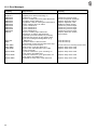
13.
13.1
13.2
Step Motor Output
Programing Switches on the Front . . . . . . . . . . . . . . . . . . . . . . . . . . . . . . . . .
Displays on the Front . . . . . . . . . . . . . . . . . . . . . . . . . . . . . . . . . . . . . . . . .
41
41
.
.
.
.
.
.
1. General
The MICROCONTROL controls of the DÜRKOPP ADLER 745-22;-23;
-24 include the integrated comprehensive MULTITEST testing and
monitoring system.
A microcomputer assumes the control tasks, monitors the sewing
process and signals operating faults and malfunctions.
Special programs facilitate mechanical adjustments and make
possible a rapid testing of the input and output elements without
additional measuring apparatus.
Errors and test results are shown in a 2 x 16 digit display.
Under normal working conditions the display shows information to
operation and the sewing process.
When an operating error or malfunction occurs the functions are
interrupted. The cause is shown in the display by the appropriate error
symbol.
In most cases the error symbol will disappear when the cause of the
fault has been remedied.
In some cases the main switch must be turned off during error
correction for safety reasons.
A portion of the error messages are meant only for the service
personnel.
All functions can be called up and changed by pressing the
appropriate key. The unit must be in its initial position for this.
When the unit is switched on the controls conduct several
comprehensive self-tests. Among other things the program and data
memories and the display are checked for flawless operation at this
time.
After the machine is switched off the set values of the individual
functions are stored in the program and data memories (battery
buffered) and automatically activated when switched on
again.
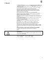
ATTENTION !
The controls for the Class 745-24 are not compatible with the controls
for the Class 745-22;-23.
Controls 745-22;-23: Parts no. 9850 745040
Controls 745-24:
Parts no. 9850 745030
3
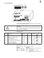
2. Description of the Controls
2.1 Keys on the Front Panel
Key
4
Function
Key
Function
Selecting Sewing and Testing Programs
Stopping the Current Program,
Activating a Selected Program
Sewing Length L1
Increase Parameter Value
Sewing Length L2
Decrease Parameter Value
Sewing Length L3
Light Barrier On
Sewing a Seam Series
Selecting the Positioning Point
Correcting of Seam Beginning/End when
Sewing Flaps with Light barrier
Tape Feed On/Off
Correcting the Corner Knives at
Seam Beginning and Seam End
Tacking On/Off
Setting Tape Length when Sewing with
Light Barrier
Selecting the Closing Order of the
Flap Clamps
Setting the Counter
Center Knife and Corner Knife
On/Off
2.2 Internal Switches
DIP-Schalter b417
b401
b402
on
off
In the control behind the display there are three pre-selector switches
for setting certain machine parameters.
CAUTION !
The switches are only evaluated once when the sewing unit is turned
on.
After changing a switch setting switch the main switch off and then on
again or operate the STOP key.
DIP-Switch b417:
745-22;-23
OFF
ON
OFF
745-24
ON
b417
Function
.1
.2
.3
.4
.5
.6
.7
.8
Stitch Length
2,5 mm
3,2 mm
2,5 mm
3,2 mm
Stitch Condensation Stitch Length
0,8 mm
1,4 mm
0,8 mm
1,4 mm
Maximum Sewing Length
180 mm
200 mm
180 mm
200 mm
Thread Monitor
ON
OFF
No function
Locking Vacuum (b8 / s14)
OFF
ON
OFF
ON
Late Opening of the Flap Clamps
OFF
ON
OFF
ON
with Reverser Device
OFF
ON
No function
Continuous Operation
OFF
ON
OFF
ON*
(only in combination with .4 "OFF")
* Thread monitor is turned off
745-22;-24: b417.7 = OFF
745-23:
b417.7 = ON (with Reverser Device)
Dial b401:
Dial b402:
Sewing Revolutions
Operation Mode of the Left Transport Clamp
b401 = 1
2500 1/min
b402 = 0 No function
b401 = 2
2750 1/min
b402 = 1 Lower left transport clamp
b401 = 3
3000 1/min
separately
b402 = 2 Lower left transport clamp with the
right
5
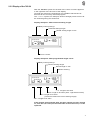
2.3 Display
The Microcontrol is equipped with a 2 x 16-digit display.
It shows the program number, sewing lengths, bobbin thread reserve
and piece count. By operating errors or malfunctions the functions are
interrupted and the cause shown by the appropriate error symbol.
The operational readiness of the sewing unit is shown by having the
current parameters in the display. The settings are the same as those
last selected before the machine was switched off.
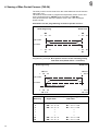
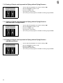
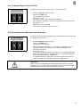
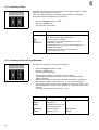
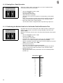
2.3.1 Display of the 745-22;-23
Display example 1: With selected sewing length
Program number
Selected sewing length
Stored sewing length in mm
Bobbin thread reserve
Piece counter
Display example 2: With programmed length series
Program number
Current sewing length
Stored length in mm
Then stacking
4. Length to be sewn
3. Length to be sewn
(Current sewing distance is underlined)
2. Length to be sewn
1. Length to be sewn
6
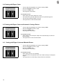
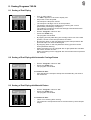
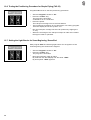
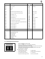
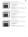
2.3.2 Display of the 745-24
With the 745-24 a symbol for the bias of the corner incisions appears
in the right half of the first line of the display.
Through this symbol the seamstress can establish which bias has
been set for the currently selected program.
The "=====" symbol, for example, denotes straight pocket corners at
the seam beginning and seam end.
Display example 1: With selected sewing length
Bias pocket openings
Selected sewing length
Stored sewing length in mm
Piece counter
Display example 2: With programmed length series
Bias pocket openings
Current sewing length
Stored length in mm
Then stacking
4. Length to be sewn
3. Length to be sewn (here: Light barrier seam)
2. Length to be sewn
(The arrow marks the current sewing length)
1. Length to be sewn
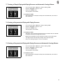
If the display remains blank after the main switch has been turned
on, then the 1,6 A fuse(on the underside of the mains unit) is to be
replaced.
7
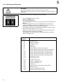
3. Description of the Function Keys
The values for the various functions can be set as follows:
– Call up the desired function by pressing the appropriate function
key.
The function will be shown in the display with a blinking cursor.
– Change the set value with the "+ / -" keys.
– Press the same function key again.
The change is completed.
The unit is ready to start again.
3.1 Selecting and Changing Sewing Length
With the L1, L2 and L3 keys three sewing lengths stored in memory
can be selected. A change of the sewing length can only occur before
the feed procedure has begun.
– Select the stored sewing length by pressing the key L1, L2 or L3.
The selected sewing length is shown in the right half of the first
display line.
– If "L?" appears in the display, then a sewing length without an
allowable value in memory was selected.
Enter an allowable value with the "+/-" keys or select a different
sewing length.
– Change the set sewing length with the "+/-" keys.
– Press the function key (L1, L2 or L3).
The set sewing length will be stored in memory.
It will remain in memory until it is changed again.
– For further details see chapter 5 and 6 ("Sewing Programs").
CAUTION !
When changing the sewing length L1 it is essential that the corner
knife interval also be altered at the same time.
Setting the Corner Knife Interval
That sewing length which is most often sewn should be stored under
L1.
The interval between the corner knives must be set so that it is the
same as the sewing length stored under L1.
With all other sewing lengths the corner incision occurs seperately in
two strokes. After the incision of the first corner knife the material is
transported to the second corner knife.
Exception:
With Class 745-23 the corner knives must always be switched on or off
together.
Positioning the Material
– With short seams under 75 mm place the material at the forward
positioning point.
– If, by sewing lengths under 75 mm, the rear positioning point is
ERROR" will appear in the
chosen, then the error message "
display. You must then change to the forward positioning point.
– With placing at the rear positioning point the following condition
must be satisfied: L1 - L2(L3) < 50
ERROR" will appear in the
Otherwise the error message "
display. You must then change to the forward positioning point.
8
3.2 Sewing of a Seam Series
With the aid of the "F" key a stored series of up to four seams can be
called up.
745-22;-23:The series can be made up of any desired order of the
three sewing lengths L1, L2 and L3.
745-24:
The series can be made up of any desired order of the
sewing lengths L1, L2, L3 and the light barrier seams LX1,
LX2 and LX3.
Calling up the Series
– Call up the series by pressing the key "F".
The series is shown in the lower display line.
The current sewing length has a special marking:
745-22;-23: The current sewing length is underlined (e.g. "L2").
745-24:
The current sewing length is preceded by an arrow
(e.g. "->L1").
The current sewing length with the appropriate value in millimeters
is shown in the right half of the upper display line (see display
example 2).
– A star "*" behind a sewing length means that stacking occurs after
this length is sewn.
Without stacking the material is transported back to the feed area
after sewing.
Then the next sewing length is automatically activated.
– Using the "+/-" keys any desired sewing length in the series can be
activated.
Key "+":
Cursor to the right
Key " -":
Cursor to the left
– To exit from the series press the keys L1, L2 or L3.
The approriate sewing length (L1, L2 or L3) is activated.
– To exit form the series with the 745-24 press the key " ".
The light barrier seam is activated.
Programming a New Series
The values for the programmed sewing lengths must established
before entering the series mode (see "Selecting and Adjusting the
Sewing Length").
– Press and hold the key "F".
– At the same time press the key "-".
The previous series is erased.
– By pressing the keys L1, L2 and L3 up to four sewing lengths can
be entered in the desired order.
– 745-24 only: After selecting a sewing length the following functions
can be set for this length using the appropriate keys:
Light Barrier On / Off
Positioning Point
Tape Feed On / Off
Tacking On / Off
Closing Order of the Flap Clamps
Corner and Center Knives On / Off
9
CAUTION !
The functions set with the keys only valid for the sewing program in
the series mode.
The settings have no effect on the sewing programm beyond the
series mode.
–
–
–
745-24: Each entry of a sewing length must be confirmed with the
"Σ" key.
745-24: Programming the light barrier seam LX1, LX2 or LX3:
Press the "
" key until the desired light barrier seam X1, X2 or
X3 appears in the display.
Set the desired functions for the selected sewing lenght using the
keys listed on page 9.
Confirm with the "Σ" key.
After selecting a sewing length (L1, L2 or L3) stacking after this
sewing length can be programmed by pressing the "+" key.
CAUTION !
With the 745-24 the selection of the sewing length and the functions
must first be confirmed with the "Σ" key.
Then stacking after this sewing length can be programmed by pressing
the "+" key.
–
–
By pressing the "-" key the last entry is erased.
To start the series press the key "F" again.
The first sewing length is automatically set.
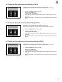
3.3 Setting the Piece Counter
By pressing this key the piece counter is reset to 0000.
The current piece count is shown in the left half of the lower display
line. The piece counter shows the number of pieces made since the
last resetting of the counter.
3.4 Selecting the Positioning Point
Depending on the type of sewing pieces the feed occurs at the forward
or rear positioning point.
By pressing this key the positioning point is changed.
If the LED above the key is lit then the forward positioning point was
selected.
The changeover between manual and automatic alteration of the
positioning points occurs in program P42.
3.5 Switching the Tape Feed On/Off
By pressing this key the tape feed is switched on and off.
If the LED above this key is lit then the tape feed is switched on.
10
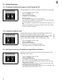
3.6 Switching Tacking On/Off
By pressing this key tacking is switched on and off.
If the LED above the key is lit then tacking is switched on.
CAUTION !
With 1.4 mm stitch length in stitch condensation
tacking is generally switched off.
3.7 Selecting the Closing Order of the Flap Clamps
With this key the order of the closing of the flap clamps can be set.
In sewing programs P07 to P12 the order of the closing of the flap
clamps cannot be set.
Operating the key switches between four possibilities.
The order is shown by the two LEDs above the key:
– Both LEDs lit:
The flap clamps close at the same time.
– Only the left LED is lit:
First the left flap clamp closes, then the right.
– Only the right LED is lit:
First the right flap clamp closes, then the left.
– Both LEDs are off:
Operation without flap clamps (optimally timed procedure).
The timing for the opening of the flap clamps in the feed area is
established by the setting of the preselector switch b417.6 inside the
controls (see "Internal Switches"):
– In the OFF setting the flap clamps open after the transport clasp
lowers.
– In the ON setting the flap clamps open after the folder lowers.
3.8 Switching the Corner and Center Knives On/Off
With this key the corner knives or the center and corner knives can be
switched on and off.
In sewing programs P07 to P12 the corner and the center knives
cannot be switched off.
Operating the key switches between three possibilities.
The different settings are shown by the two LEDs above the key:
– Both LEDs are lit:
Corner and center knives are switched on.
– Only the right LED is lit:
The corner knives are switched off.
– Both LEDs are off:
All knives are switched off.
11
3.9 Switching On the Light Barrier
By pressing this key the light barrier is switched on.
The light barrier recognizes the seam beginning and seam end on
flaps.
The light barrier cannot be activated in the operating modes for piping
reversing and zippers.
– Press the key.
The lit LED above the key signals, that the light barrier is switched
on.
745-22;-23: Instead of the sewing lengths L1, L2, L3, the display
shows "LX".
745-24:
Through repeated pressing of the key, the display
shows the light barrier seams LX1, LX2 and LX3 in
sequence.
– To switch off the light barrier press one of the keys L1, L2 or L3.
CAUTION !
When sewing with the light barrier, the flap must be placed between
the two positioning points.
If the flap is positioned in front of the forward or extends beyond the
rear positioning point, the error message "LS" appears in the display.
3.10 Correcting the Seam Beginning and Seam End
This key calls up the correction function for seam beginning and seam
end.
The correction of seam beginning (NA) and seam end (NE) occurs for
the sewing lengths L1, L2, L3 and for the light barrier seams LX
(745-22;-23) and LX1, LX2, LX3 (745-24).
By changing the values for NA and NE the corner knife action is
appropriately adjusted for sewing with the light barrier.
– Press the function key.
The set values for NA and NE are shown in the display.
– Increase or decrease the value for NA in steps by pressing the
"+/-" keys.
Minimum:
Maximum:
Median value:
Step distance:
–
–
–
12
0
99
50 (no correction)
1 cycle = 0.085 mm
Press the function key again.
This switches from NA to NE.
Increase or decrease the value for NE in steps by pressing the
"+/-" keys.
Complete the correction procedure by calling up the selected
sewing length.
3.11 Correcting the Corner Knives
This key calls up the correction function for the corner knives at the
seam beginning (MA) and the seam end (ME).
The correction can be made for the sewing lengths L1, L2, L3 as well
as for the light barrier seams LX (745-22;-23) and LX1, LX2 and LX3
(745-24).
– Press the function key.
The set values for MA and ME will be shown in the display.
– Increase or decrease the value for MA in steps by pressing the
"+/-" keys.
Minimum:
Maximum:
Median value:
Step distance:
–
–
–
0
99
50 (no correction)
1 cycle = 0.085 mm
Press the function key again.
This switches from MA to ME.
Increase or decrease the value for ME in steps by pressing the
"+/-" keys.
Complete the correction procedure by calling up the selected
sewing length.
CAUTION !
With the 745-23 the corner knives must always be switched on or off
together.
Set the parameters MA and ME at the median value 50.
Special note for 745-23:
When sewing with piping reverser only sewing length L1 can be set.
3.12 Tape Length when Sewing with Light Barrier
This key sets the tape length at the seam end when sewing with light
barrier.
The set value corresponds to the distance from the initial position of
the transport clasps to cutting.
– Switch on the tape feed.
– Press the function key.
The set value for the tape length is shown in the display.
– Increase or decrease the tape length in steps by pressing the
"+/-" keys.
Minimum:
Maximum:
Step distance:
–
20 mm
100 mm
1 cycle = 1 mm
Complete the setting procedure by calling up the selected sewing
length.
13
4. Sewing of Bias Pocket Corners (745-24)
The bias pocket corners result from the offset between the left and the
right seam row.
The desired seam offset is programmed separately at the control unit
for the seam beginning (BR,BL) and the seam end (ER,EL).
If all parameters are set to the median value "10", then a straight
pocket results.
Parameters for the programming of the bias pocket corners:
Seam beginning
Seam end
BR
1 ... 10 ... 20
ER
1 ... 10 ... 20
Right seam
Left seam
1 ... 10 ... 20
BL
1 ... 10 ... 20
EL
Programming example: Bias pocket corners at the seam beginning
and seam end (Seam offset = 2 stitches)
Seam beginning
Seam end
BR = 9
1 ... 10 ... 20
ER = 9
1 .. 10..20
Right seam
Left seam
Seam offset = 2 stitches
1 ... 10 ... 20
BL = 11
Seam offset
[Stitches]
2
4
6
•
•
•
16
18
14
1 . 10..20
EL = 11
Parameter to be set (Seam beginning)
Right seam
Left seam
BR = 10 - 1 = 9
BR = 10 - 2 = 8
BR = 10 - 3 = 7
•
•
•
BR = 10 - 8 = 2
BR = 10 - 9 = 1
BL = 10 + 1
BL = 10 + 2
BL = 10 + 3
•
•
•
BL = 10 + 8
BL = 10 + 9
= 11
= 12
= 13
= 18
= 19
Display example: Straight pocket corners
BL = Beginning-left needle
BR = Beginning-right needle
ER = End-right needle
EL = End-left needle
Selected sewing distance
Programming the bias of the pocket corners:
–
–
–
–
Simultaneously press the key for the desired sewing distance (L1,
L2 or L3) and the "
" key.
For selecting a light barrier seam:
Press the "
" key until the desired light barrier seam LX1, LX2
or LX3 appears in the display.
Simultaneously press the "
" and the "
" keys.
The parameters for the programmed bias of the selected sewing
distance appear in the display (see display example).
Increase or decrease the parameter values in steps by pressing
the "+/-" keys.
Minimum: 1
Maximum:20
Median value: 10 (straight pocket corner)
Steps: 1 step = 1 stitch of the current stitch condensation
–
–
Attention!
The left and right seam rows must always be offset an equal
number of stitches with reference to the median value "10".
The parameters BR and BL to be set for the desired seam offset
can be found in the table on page 14.
The parameters ER and EL are arrived at in the same manner.
Press the "Σ" key.
The cursor moves to the next parameter.
Complete the setting procedure by pressing the key for the
selected sewing distance L1, L2, L3 or the "
" key (for light
barrier seams).
ATTENTION !
With bias pockets the following additional setting work must be
conducted:
– Manually adjust the angle and height of the corner knives
according to the programmed seam offset (see Operating
Instructions)
or:
Switch the corner knives off via the "
" key on the controlunit.
15
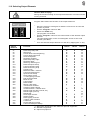
5. Selecting the Sewing and Testing Programs
The sewing and testing programs listed below can be selected with the
"Program" preselector switch.
– Set the "Program" switch to the desired program.
– Switch on the main switch or press the key "STOP".
The desired program is activated.
– If the symbol "P?" appears in the right half of the first display line,
then an illegal program number was selected.
A sewing procedure running at the time the "STOP" key was
operated will be cancelled.
– Correct the setting and press the "STOP" switch.
Switch
Program
00
P00
Display of the Program Version
01
02
03
04
05
06
P01
P02
P03
P04
P05
P06
Sewing program
as P01, with automatic carriage return
as P01, with material return
as P01, with zipper cutter
as P04, with automatic carriage return
as P04, with material return
07
08
09
10
11
12
13
14
15
P07
P08
P09
P10
P11
P12
P13
P14
P15
as
as
as
as
as
as
as
as
as
40
41
42
43
44
45
46
47
P40
P41
P42
P43
P44
P45
P46
P47
Center knife adjustment
Setting the bobbin thread counter
Changing the positioning point manual/automatic
Testing the piping reverser for dual piping
Testing the piping reverser for simple piping
Testing the piping reverser for asymmetrical piping
Testing the positioning procedure (dual piping)
Loading of standard values
X
X
X
51
52
53
54
55
56
57
58
59
60
61
62
63
64
65
66
67
68
69
P51
P52
P53
P54
P55
P56
P57
P58
P59
P60
P61
P62
P63
P64
P65
P66
P67
P68
P69
Setting the remaining thread monitor
Testing the zipper cutter
Checking the needle and center knife actuation
Testing the positioning procedure (simple piping)
Setting the light barrier for seam beginning/end
Setting the material strip reverser
Checking the step motor control
Checking the serial interface
Testing the timer and memory
Checking continuity
Checking the front panel elements
Checking the input elements
Selecting input elements
Selecting output elements
Sewing drive: pedal operation
Sewing drive: set value X, position 2
Sewing drive: set value X, position 1
Sewing drive: set value X, position 1, position 2
Sewing drive: set value X, position 2,
with thread trimming procedure
X
X
X
16
Function
Subclass
745-22 745-23 745-24
X
X
X
X
X
X
X
X
X
X
X
X
X
X
X
X
X
X
X
X
X
X
X
X
P01, with piping reverser for dual piping
P07, with material return
P01, with piping reverser for simple piping
P09, with automatic carriage return
P01, with piping reverser for asymmetr. piping
P11, with material return
P01
without piping reverser for
P02
asymmetrical piping and
P03
simple piping
X
X
X
X
X
X
X
X
X
X
X
X
X
X
X
X
X
X
X
X
X
X
X
X
X
X
X
X
X
X
X
X
X
X
X
X
X
X
X
X
X
X
X
X
X
X
X
X
X
X
X
X
X
X
X
X
X
X
X
X
6. Sewing Programs 745-22
6.1 Sewing of Simple, Dual and Asymmetrical Piping
–
–
–
–
–
–
–
–
–
–
Turn the DIP-Switch b417.7 in switch setting "OFF".
Turn on main switch.
"<---REF" appears in the lower display line.
Step back on the left pedal.
The transport clasps are raised.
The transport carriage runs to its rear position.
The display signals start readiness by showing the current
parameters (see display example 1).
The settings correspond to the last settings selected before the
machine was turned off.
Set the "Program" switch to "01".
Press the "STOP" key.
The program is activated.
By tapping the left pedal bring the carriage return out of the hold
position, switch on the feed procedure and start.
By stepping back on the left pedal during the feed procedure the
previous steps can be activated again.
By stepping back on the left pedal the sewing process can be
interrupted after starting.
When the sewing unit is equipped with a right pedal this activates
the holder and the vacuum.
When the sewing unit is equipped with a knee switch this operates
the vacuum.
6.2 Sewing with Automatic Carriage Return
–
–
–
Turn the DIP-Switch b417.7 in switch setting "OFF".
Set the "Program" switch to "02".
Press the "STOP" key.
The program is activated.
In contrast to P01:
– After stacking the transport clasps are automatically run back to
the feed area.
6.3 Sewing with Material Return
–
–
–
Turn the DIP-Switch b417.7 in switch setting "OFF".
Set the "Program" switch to "03".
Press the "STOP" key.
The program is activated.
In contrast to P01:
– There is no stacking after sewing.
– The material is transported back to the feed area by the transport
clasps.
17
6.4 Sewing with Zipper Cutter
–
–
–
In
–
–
–
–
Turn the DIP-Switch b417.7 in switch setting "OFF".
Set the "Program" switch to "04".
Press the "STOP" key.
The program is activated.
contrast to P01:
After sewing the sewn zipper is cut off.
The material is generally placed at the rear positioning point.
The shortest sewing length is 75 mm.
The light barrier cannot be activated.
6.5 Sewing with Zipper Cutter and Automatic Carriage Return
–
–
–
Turn the DIP-Switch b417.7 in switch setting "OFF".
Set the "Program" switch to "05".
Press the "STOP" key.
The program is activated.
In contrast to P04:
– After stacking the transport clasps are automatically run back to
the feed area.
– The light barrier cannot be activated.
6.6 Sewing with Zipper Cutter and Material Return
–
–
–
Turn the DIP-Switch b417.7 in switch setting "OFF".
Set the "Program" switch to "06".
Press the "STOP" key.
The program is activated.
In contrast to P04:
– After sewing there is no stacking.
– The material is transported back to the feed area by the transport
clasps.
– The light barrier and the flap clamp cannot be activated.
18
7. Sewing Programs 745-23
7.1 Sewing of Dual Piping
–
–
–
–
–
–
–
–
–
–
Turn the DIP-Switch b417.7 in switch setting "ON".
Turn on main switch.
"<---REF" appears in the lower display line.
Step back on the left pedal.
The transport clasps are raised.
The transport carriage runs to its rear position.
The display signals start readiness by showing the current
parameters (see display example 1).
The settings correspond to the last settings selected before the
machine was turned off.
Set the "Program" switch to "01".
Press the "STOP" key.
The program is activated.
By tapping the left pedal bring the carriage return out of the hold
position, switch on the feed procedure and start.
By stepping back on the left pedal during the feed procedure the
previous steps can be activated again.
By stepping back on the left pedal the sewing process can be
interrupted after starting.
When the sewing unit is equipped with a right pedal this activates
the holder and the vacuum.
When the sewing unit is equipped with a knee switch this operates
the vacuum.
7.2 Sewing of Dual Piping with Automatic Carriage Return
–
–
–
Turn the DIP-Switch b417.7 in switch setting "ON".
Set the "Program" switch to "02".
Press the "STOP" key.
The program is activated.
In contrast to P01:
– After stacking the transport clasps are automatically run back to
the feed area.
7.3 Sewing of Dual Piping with Material Return
–
–
–
Turn the DIP-Switch b417.7 in switch setting "ON".
Set the "Program" switch to "03".
Press the "STOP" key.
The program is activated.
In contrast to P01:
– There is no stacking after sewing.
– The material is transported back to the feed area by the transport
clasps.
19
7.4 Sewing of Dual Piping with Piping Reverser
–
–
–
Turn the DIP-Switch b417.7 in switch setting "ON".
Set the "Program" switch to "07".
Press the "STOP" key.
The program is activated.
In contrast to P01:
– After the corner incision the pipings are reversed and the material
overlaps are drawn through the incision.
– The light barrier and the flap clamp cannot be activated.
– Only one sewing length L1 can be activated.
7.5 Sewing of Dual Piping with Piping Reverser and Automatic Carriage Return
–
–
–
Turn the DIP-Switch b417.7 in switch setting "ON".
Set the "Program" switch to "08".
Press the "STOP" key.
The program is activated.
In contrast to P07:
– After stacking the transport clasps are automatically run back to
the feed area.
7.6 Sewing of Simple Piping with Piping Reverser
Presupposition: Optional equipment 0792 030901 (Reverser device
for simple piping) required.
–
–
–
Turn the DIP-Switch b417.7 in switch setting "ON".
Set the "Program" switch to "09".
Press the "STOP" key.
The program is activated.
In contrast to P01:
– After the corner incision the piping is reversed and the material
overlap of the piping and the right material strip is drawn through
the incision.
– Before this operation the left transport clasp is removed aside.
– The light barrier and the flap clamp cannot be activated.
– Only one sewing length L1 can be activated.
20
7.7 Sewing of Simple Piping with Piping Reverser and Automatic Carriage Return
–
–
–
Turn the DIP-Switch b417.7 in switch setting "ON".
Set the "Program" switch to "10".
Press the "STOP" key.
The program is activated.
In contrast to P09:
– After stacking the transport clasps are automatically run back to
the feed area.
7.8 Sewing of Asymmetrical Piping with Piping Reverser
–
–
–
Turn the DIP-Switch b417.7 in switch setting "ON".
Set the "Program" switch to "11".
Press the "STOP" key.
The program is activated.
In contrast to P01:
– After the corner incision the pipings are reversed and the material
overlaps are drawn through the incision.
– Before this operation the left transport clasp is removed aside.
– The light barrier and the flap clamp cannot be activated.
– Only one sewing length L1 can be activated.
7.9 Sewing of Asymmetrical Piping with Piping Reverser and Automatic Carriage Return
–
–
–
Turn the DIP-Switch b417.7 in switch setting "ON".
Set the "Program" switch to "12".
Press the "STOP" key.
The program is activated.
In contrast to P11:
– After stacking the transport clasps are automatically run back to
the feed area.
21
7.10 Sewing of Simple and Asymmetrical Piping without Piping Reverser
–
–
–
–
Turn the DIP-Switch b417.7 in switch setting "ON".
Set the "Program" switch to "13".
Press the "STOP" key.
The program is activated.
The running of the program is suitable to sewing program P01.
7.11 Sewing of Simple and Asymmetrical Piping without Piping Reverser
with Automatic Carriage Return
–
–
–
–
Turn the DIP-Switch b417.7 in switch setting "ON".
Set the "Program" switch to "14".
Press the "STOP" key.
The program is activated.
The running of the program is suitable to sewing program P02.
7.12 Sewing of Simple and Asymmetrical Piping without Piping Reverser
with Material Return
–
–
–
–
22
Turn the DIP-Switch b417.7 in switch setting "ON".
Set the "Program" switch to "15".
Press the "STOP" key.
The program is activated.
The running of the program is suitable to sewing program P03.
8. Sewing Programs 745-24
8.1 Sewing of Dual Piping
–
–
–
–
–
–
–
–
–
Turn on main switch.
"<---REF" appears in the lower display line.
Step back on the left pedal.
The transport clasps are raised.
The transport carriage runs to its rear position.
The display signals start readiness by showing the current
parameters (see display example 1).
The settings correspond to the last settings selected before the
machine was turned off.
Set the "Program" switch to "01".
Press the "STOP" key.
The program is activated.
By tapping the left pedal bring the carriage return out of the hold
position, switch on the feed procedure and start.
By stepping back on the left pedal during the feed procedure the
previous steps can be activated again.
By stepping back on the left pedal the sewing process can be
interrupted after starting.
When the sewing unit is equipped with a right pedal this activates
the holder and the vacuum.
When the sewing unit is equipped with a knee switch this operates
the vacuum.
8.2 Sewing of Dual Piping with Automatic Carriage Return
–
–
Set the "Program" switch to "02".
Press the "STOP" key.
The program is activated.
In contrast to P01:
– After stacking the transport clasps are automatically run back to
the feed area.
8.3 Sewing of Dual Piping with Material Return
–
–
Set the "Program" switch to "03".
Press the "STOP" key.
The program is activated.
In contrast to P01:
– There is no stacking after sewing.
– The material is transported back to the feed area by the transport
clasps.
23
9. Aid Programs
9.1 Center Knife Adjustment
Program P40 alters the incision of the center knife.
If a higher value is selected the incision moves to the outside at the
seam beginning and at the seam end.
With a smaller value the incision moves in the seam.
–
–
–
Set the "Program" switch to "40".
Press the "STOP" key.
The program is activated.
The lower left display line shows the current value for the center
knife incision.
Correct the set value with the "+/ -" keys.
9.2 Setting the Bobbin Thread Counter (745-22;-23)
With the sub-classes 745-22 and 745-23 the bobbin thread is
monitored by a countdown counter.
The setting of this counter is made with program P41.
–
–
–
–
–
Set the "Program" switch to "41".
Press the "STOP" key.
The program is activated.
The lower display line shows the preset value.
The position to be set blinks.
Set the desired value for each of the positions with the "+/ -" keys.
The next higher position is selected with the key "Σ".
By operating both keys "+" and "-" at the same time the counter is
reset to "0000".
Setting the value "0000" causes the bobbin thread monitor to
be shut off by the counter.
Note:
The set value multiplied by factor four is approx. the number of
possible stitches.
9.3 Changing the Positioning Point Manual/Automatic
Program P42 switches over between manual and automatic changing
of positioning point.
An automatic change is only possible when sewing a sewing length.
–
–
–
24
Set the "Program" switch to "42".
Press the "STOP" key.
The program is activated.
The set status is shown in the display.
The switch over between manual and automatic change is made
with key "Σ".
9.4 Testing the Piping Reverser for Dual Piping (745-23)
Program P43 corresponds to sewing program P07.
During the reversing procedure there is a stop after each step.
–
–
–
–
Set the "Program" switch to "43".
Press the "STOP" key.
The program is activated.
After the first step of the draw-through procedure the process is
stopped.
By pressing the "+" key the process is continued to the next stop
point.
9.5 Testing the Piping Reverser for Simple Piping (745-23)
Program P44 corresponds to sewing program P07.
During the reversing procedure there is a stop after each step.
–
–
–
–
Set the "Program" switch to "44".
Press the "STOP" key.
The program is activated.
After the first step of the draw-through procedure the process is
stopped.
By pressing the "+" key the process is continued to the next stop
point.
9.6 Testing the Piping Reverser for Asymmetrical Piping (745-23)
Program P45 corresponds to sewing program P11.
During the reversing procedure there is a stop after each step.
–
–
–
–
Set the "Program" switch to "45".
Press the "STOP" key.
The program is activated.
After the first step of the draw-through procedure the process is
stopped.
By pressing the "+" key the process is continued to the next stop
point.
25
10. Setting Programs
10.1 Testing the Positioning Procedure for Dual Piping (745-23)
Program P46 serves to test the positioning procedure for dual piping.
–
–
–
–
–
–
Set the "Program" switch to "46".
Press the "STOP" key.
The program is activated.
A reference run is conducted.
Press the pedal.
The transport carriage runs to the feed station.
The positioning procedure is run through as in a sewing program.
Then the display shows the symbol "<---".
Run the transport carriage into the rear position by tapping the "Σ"
key.
When the rear edge of the transport clasps is under the needles
the zipper cutter is operated.
10.2 Loading of standard values
Program P47 serves for loading of the following standard values:
Correction seam beginning (NA) / seam end (NE):
Correction of corner knife seam beginning (MA) / seam end (ME):
745-24: Seam beginning (BL) / seam end (EL) left needle:
745-24: Seam beginning (BR) / seam end (ER) right needle:
7
–
–
–
50
50
10
10
Set the "Program" switch to "47".
Press the "STOP" key.
The program is activated.
Press the "Σ" key for starting the program.
The display shows the loaded standard values.
10.3 Setting the Remaining Thread Monitor (Light Reflection Barriers)
Program P51 serves for aligning the light reflection barriers of the
remaining thread monitor.
–
–
–
26
Set the "Program" switch to "51".
Press the "STOP" key.
The program is activated.
The middle of the lower display line shows two bobbins.
With correctly aligned light barriers a reflection occurs when an
empty bobbin is turned.
A reflection of the left light barrier is shown in the left half of the
lower display line by the symbol "]->>".
A reflection of the right light barrier is shown in the right half of the
lower display line by the symbol "<<-[".
10.4 Testing the Zipper Cutter (745-22)
Program P52 can start a zipper cutter cutting sequence.
–
–
–
–
–
Set the "Program" switch to "52".
Press the "STOP" key.
The program is activated.
Press the "Σ" key.
The zipper cutter cutting sequence is started.
If the transport carriage is not in its rear position, this is shown by
the symbol "<---".
Step back on the left pedal.
The transport carriage runs to the rear.
10.5 Checking Needle and Center Knife Actuation
Program P53 checks the actuation of the needles and center knife with
the sewing drive running.
–
–
–
–
–
Set the "Program" switch to "53".
Press the "STOP" key.
The program is activated.
Set the desired revolutions (1 - 13) with the "Program" switch.
The lower display line shows the set value belonging to the
selected revolutions.
Press the "Σ" key.
The sewing drive starts and runs until the "Σ" key is pressed again.
When the sewing drive is stopped there is a positioning sequence
in the 2nd needle position (needle up).
The needles and the center knife can be actuated at any time by
pressing the key "L1" (needles) and "L2" (center knife).
CAUTION !
When exiting program P53 it is essential that the machine head be
allowed to run for a short time with needles and center knife shut off.
Otherwise the next seam will not be sewn correctly.
27
10.6 Testing the Positioning Procedure for Simple Piping (745-23)
Program P54 serves to test the positioning procedure.
–
–
–
–
–
–
Set the "Program" switch to "54".
Press the "STOP" key.
The program is activated.
A reference run is conducted.
Press the pedal.
The transport carriage runs to the feed station.
The positioning procedure is run through as in a sewing program.
Then the display shows the symbol "<---".
Run the transport carriage into the rear position by tapping the
"Σ" key.
When the rear edge of the transport clasps is under the needles
the zipper cutter is operated.
10.7 Setting the Light Barrier for Seam Beginning / Seam End
With program P55 the reflecting light barrier for recognition of the
seam beginning and seam end is aligned.
–
–
–
28
Set the "Program" switch to "55".
Press the "STOP" key.
The program is activated.
Move the transport clasp by hand.
By reflection the first display line will show "+B44".
By interruption "-B44" appears.
10.8 Setting the Material Strip Reverser (745-23)
–
–
–
–
–
Set the "Program" switch to "56".
Press the "STOP" key.
The program is activated.
Press the "Σ" key.
The material and piping reverser is switched on and off.
If the transport carriage is not in its rear position, this is shown by
the symbol "<---".
Step back on the left pedal.
The transport carriage runs to the rear.
29
11. Testing Programs
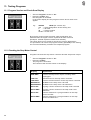
11.1 Program Version and Check-Sum Display
–
–
Set the "Program" switch to "00".
Press the "STOP" key.
Das Program ist activated.
In the lower display line the program version and a check-sum
appear.
e.g.:
745P06
745 =
P
=
06
=
CE9D=
CE9D (for 745-22;-23)
Class designation of the sewing unit
ID letter
Series number
Check-sum
By program versions with the same class designation and
same ID letter the higher version replaces all lower versions
(Example: 745P03 replaces 745P01 and 745P02).
The check-Sum is only meant for the factory service department.
In it specialists can see if the program memory (EPROM) of the sewing
unit controls faultlessly contains the complete program.
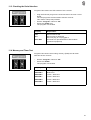
11.2 Checking the Step Motor Control
Program P57 tests the step motor controller and the step motor output.
–
–
Set the "Program" switch to "57".
Press the "STOP".
The program is activated.
The results of the test are shown in the display.
Display
Explanation
AMP ERR
Fault in the step motor output or linking cable
unplugged
Transmission to the step motor controller
Fault in the transmission to the step motor controller
EPROM on the step motor card OK
EPROM on the step motor card defective
Cycling counter module on the step motor card OK
Cycling counter module on the step motor card
defective
Counter module for cycle generation on the step
motor card OK
Counter module for cycle generation on the step
motor card defective
LINK OK
LINK ERR
EPROM OK
EPROM ERR
XCOU OK
XCOU ERR
SCOU OK
SCOU ERR
30
11.3 Checking the Serial Interface
Program P58 checks the SIO module of the controls.
–
–
–
Plug the SIO test plug into the socket b109 on the main circuit
board.
The test plug links the transmitter with the receiver.
This makes a loop test possible.
Set the "Program" switch to "58".
Press the "STOP" key.
The program is activated.
Display
Explanation
OK
Err
SIO module is OK
SIO module is defective
SIO test plug is not plugged in
Controls are operated without SIO module
(optional equipment)
kein SIO
11.4 Memory and Timer Test
Program P59 checks the working memory (RAM) and all timer
switches of the controls.
–
–
Set the "Program" switch to "59".
Press the "STOP".
The program is activated.
Display
Explanation
OK
ERROR
ERROR
ERROR
ERROR
ERROR
Working memory and all timer switches are OK
RAM error
Timer 1 defective
Timer 2 defective
Timer 3 defective
Timer 4 defective
0
6
7
8
9
31
11.5 Continuity Check
Program P60 checks to see if the 24V current supply supplies current
when the output drivers are shut off.
Then the program checks all existing output elements (including
output drivers and installation) for continuity.
–
–
Set the "Program" switch to "60".
Press the "STOP" key.
The program is activated.
Display
Explanation
V?
Short in the installation or
one of the output drivers defective
All circuit have continuity
Interruption in the output element s17, in its
installation or driver
Output element s17 does not exist because it is
optional equipment
Continue the test with the next element
by pressing the "Σ" key.
OK
S17
(Example)
11.6 Checking the Front Panel Elements
Program P61 checks the front panel elements.
–
–
–
–
Set the "Program" switch to "61".
Press the "STOP" key.
The program is activated.
Operate the preselector switch on the front panel.
The display will show the current set value of the preselector
switch operated.
When a key on the front panel is operated (Exception: STOP key)
the numbers relating to this switch (1, 2, 4 or 8) are displayed.
The LEDs on the front panel are selected using code numbers. The
short designation from the circuit diagram (1 - 8) acts as their code
number.
The LEDs are switched on with the "Σ" key.
Switch
Function
Designation
b417
b401
b402
Function switch
Revolutions
Operation mode of the
left transport clamp
Program switch
Stop (Key 13)
PROGRAM
STOP
b413/412
b416
32
Key
Function
Symbol
Indicator
b814
Positioning point forward
LED
b815
Set counter
Display
b816
Minus
b817
Plus
b818
Center and corner knives on / off
LED / LED
b819
Order of closing of the flap clamps
LED / LED
b820
Tacking on / off
LED
b821
Tape feedon / off
LED
b822
Light barrier on
LED / Display
b823
Tape length when sewing with light barrier
Display
b824
Correction the corner knife
Display
b825
Correction of seam beginning and seam end
Display
b826
Sewing of seam series
Display
b827
Sewing length 3
Display
b828
Sewing length 2
Display
b829
Sewing length 1
Display
LED
Function Indication
H1b
H2
H3c
H4c
H5b
H6b
H7a
H8a
Positioning point forward
Light barrier NA / NE
Flap clamp left
Corner knife
Center knife
Flap clamp right
Tacking
Tape guide
11.7 Checking the Input Elements
–
–
–
Set the "Program" switch to "62".
Press the "STOP" key. The program is activated.
Press the input element to be checked.
The display will show the circuit diagram designation and switching
status of the input elements (e.g. "+B25").
The display will change when the switching status of any other
input elements is changed.
The switch status "+" means:
– for switches with contact
= contact open
– for proximity switches
= metal in front of the switch
– for reflecting light barriers
= no reflection
– Continuous beam light barrier
= beam uninterrupted
33
11.8 Selecting Input Elements
CAUTION !
All input elements have been carefully set at the factory.
Adjustment and correction may only be undertaken by trained service
personnel.
Program P63 serves for setting the input elements.
–
–
–
–
–
Set the "Program" switch to "63".
Press the "STOP" key.
The program is activated.
Set the "Program" switch to the code number of the desired input
element.
The short designation in the circuit diagram acts as the code
number (see table). This does not apply for the keys on the front
panel (see "Checking the Front Panel Elements").
The display shows the circuit diagram designation and the switch
status of the input element (e.g. "+B14").
Adjust the input element (e.g. proximity switch) until the desired
switching status is shown in the display.
The meaning of the switch status corresponds to the switching
status in program P62.
Input
Element
b1
b2
b3
b4
b5
b8
b9
b10
b11
b12
b13
b14
b15
b35
b37
b39
b44
b45
b46
b47
34
Function
Carriage at rear
Reference position
Carriage forward
Folder up
Folder down
Material holder lowered / Vacuum on
(second pedal / Knee switch, optional equipment)
Pedal 3 (External transmitter for sewing drive)
Pedal 4 (External transmitter for sewing drive)
Pedal 1 (External transmitter for sewing drive)
Pedal 2 (External transmitter for sewing drive)
Transmitter control
Thread monitor left
Thread monitor right
Position 1 (Needle down)
Position 2 (Needle up)
(Position 3)
Light barrier NA / NE (optional equipment)
Stacker control
Remaining thread monitor left
Remaining thread monitor right
11.9 Selecting Output Elements
Caution Risk of Injury !
During the function testing of the output elements do not reach into the
running machine.
Program P64 checks the function of the output elements.
–
–
–
–
–
Output
Element
s1
s2
s3
s4
s5
s6
s7
s8
s9
s10
s11
s12
s13
s14
s15
s16
s17
s18
s19
s20
s21
s22
s23
s24
s25
s26
s27
s28
s29
s30
s31
s32
Function
Move the transport carriage at a distance of 50 mm to its rear end
position by hand.
Set the "Program" switch to "64".
Press the "STOP" key.
The program is activated.
Set the "Program" switch to the code number of the desired output
element.
The short designation in the circuit diagram serves as the code
number (see table).
Turn the selected output element on and off by tapping the "Σ" key.
745-22
745-23
X
X
Raise flap clamp left
X
X
Swing link
X
X
Corner knife seam beginning
X
X
Corner knife seam end
X
X
Close fold plates
0
0
Smoother forward
X
X
Raise flap clamp right
0
0
Smoother back
X
X
Stacking / Blowing out
X
X
Raise transport clasp
X
X
Lower transport clasp
X
Raise tensioning strip
X
X
Center knife
0
0
Material holder / Vacuum
X
X
Loosen thread tension
X
X
Open thread clamp
0
Close zipper cutter
X
* Lower piping reverser
X
X
Pull thread forward
X
X
Blow out lint
X
X
Lower folder
X
X
Raise folder
0
Zipper cutter back
X
* Knife block forward
X
Transport clasp closed
X
X
Thread trimmer / Thread catch
X
X
Needle right and left (745-22;-23)
Needle right (745-24)
Needle left
0
0
Close tape trimmer
0
0
Advance tape
X
Raise piping reverser
0
* Zipper cutter forward
X
X
Lock hood
0
0
Lift left transport clamp
0
0
Lower left transport clamp
* = Alternative designation with different optional equipment
x = Standard equipment
0 = Optional equipment
745-24
X
X
X
X
X
0
X
0
X
X
X
X
0
X
X
X
X
X
X
X
X
X
0
0
X
0
0
35
11.10 Sewing Drive: Pedal Operation
After the program P65 is activated the unit can be operated with
revolutions selected via the pedal.
–
–
–
–
Set the "Program" switch to "65".
Press the "STOP" key.
The program is activated.
Step forward on the pedal.
The drive runs at those revolutions corresponding to the pedal
position.
After a few seconds the right half of the first display line shows
current revolutions (actual revolutions of the machine head).
Bring the pedal to the neutral position.
The machine head is stopped without a positioning sequence.
11.11 Positioning the Machine Head in the 2nd Needle Position/Revolution Test
Program P66 serves for setting the 2nd needle position (needle up).
After the main switch is turned on the right display half shows the
symbol "SW?".
Different revolutions of the motor can be preselected with the program
switch.
– Set the "Program" switch to "66".
– Press the "STOP" key.
The program is activated.
– Preselect the revolutions of the drive with the "Program" switch.
A total of 13 revolution stages are available (see table).
– With an allowable value the right half of the first display line shows
"0000", with an illegal value "SW?".
– Press and hold key "Σ".
The drive runs with the selected revolutions.
After a few seconds the right half of the first display line shows
current revolutions (actual revolutions of the machine head).
– Release the key "Σ".
The machine head will be positioned in the 2nd needle position
(needle up).
Revolutions 1/min
13
12
11
10
9
8
7
6
5
4
3
2
1
36
3000
2750
2500
1700
1000
720
540
410
310
230
170
130
100
11.12 Positioning the Machine Head in the 1st Needle Position
Operation of the program P67 is as described under program P66.
–
–
Set the "Program" switch to "67".
Press the "STOP" key.
The program is activated.
In contrast to P66:
– The machine head is positioned in the 1st needle position (needle
down).
The slots in the synchronizer for the two needle positions must be
opposite each other.
11.13 Positioning the Machine Head with Cutting Revolutions
Operation of the program P68 is as described under program P66.
–
–
Set the "Program" switch to "68".
Press the "STOP" key.
The program is activated.
In contrast to P66:
– The machine head is positioned in the 1st needle position (needle
down).
– After a short pause the needle is positioned in the 2nd needle
position (needle up).
11.14 Positioning the Machine Head and Thread Trimming
Operation of the program P69 is as described under program P66.
–
–
Set the "Program" switch to "69".
Press the "STOP" key.
The program is activated.
In contrast to P66:
– The positioning of the machine head in the 2nd needle position
(needle up) occurs with a thread trimming sequence.
37
12. Function Displays and Error Messages
12.1 Displays for Operating Aids
Display
Explanation
Remedy
P?
745N06
<----REF
Illegal program selected
Display of the program version
Carriage not in rear position when
switched on (reference run)
Sewing sequence interrupted, run
carriage to rear
Run carriage to rear
Entry of a new series is expected
Illegal sewing length selected
(e.g. Length in P04 - P06 smaller than
75 mm)
Fabric to be scanned by the light barrier
is positioned outside the sewing area
Positioning error, rear positioning point
chosen by sewing lengths under 75 mm
Left bobbin empty
(left blinks)
Right bobbin empty
(right blinks)
Bobbins empty (blinks)
Thread tear (blinks)
Piece counter
Bobbin thread reserve
Left bobbin thread monitor
has reflection
Right bobbin thread monitor
has reflection
Invalid revolution level set
Step motor controller being tested
Transmission to step motor
controller OK
Counter module for cycle counting on
the step motor card OK
Counter module for cycle generation on
the step motor card OK
EPROM on the step motor card OK
Reset "Program" switch
<----REF
PEDAL STOP
<---F?
---L?
LS
ERROR
I
I
I
I
I I
-- X -Σ =xxxx
I =xxxx
]->>
<<-[
SW?
SMC-TEST
LINK OK
XCOU OK
SCOU OK
EPROM OK
38
Step back on pedal
Step back on pedal
Step back on pedal
Program a new seam series
Reset sewing length
Reposition fabric inside the sewing
area
Select the front positioning point
Change left bobbin
Change right bobbin
Change bobbins
Reinsert thread
Reset "Program" switch
12.2 Displays by Malfunctions
Display
Explanation
Remedy
E2
V?
STOP
Fuse e2 in transformer defective
Error message in P60
Hood open
Hood control or Stop key defective
Machine head will not position
Synchronizer not installed,
Motor protection switch off
Synchronizer not plugged in
Short in the lead for switch on pedal,
pedal was already operated when the
main switch was turned on
Transport carriage run up against
forward stop
Transport carriage run up against rear
stop
Transport carriage run in the wrong
direction during reference run
Error during reference run
Error in the stored values
Replace fuse e2 (24V)
POS2
POS-Err
--<>-START ERROR
ERROR --> [b3
ERROR b1 ] <-? <----> ?
REF ERROR
PROG ERROR1
PROG ERROR2
? b417 ?
? b401 ?
ERROR1 LS ] <-ERROR2 LS ] <-ERROR3 LS ] <-ERROR4 LS ] <-ERROR5 LS ] <-ERRORLS --> [END
Error in storing the check-sum
b417.8 only in conjunction with b417.4
Illegal switch position by revolution
selection
No reflection at the beginning of the rail
Reflection at the beginning of the
railincorrect
Too short a flap at rear positioning point
Flap lies beyond forward positioning
point
Lint in front of flap
Flap lies beyond rear positioning point
Close hood, replace hood control or
Stop key
Install synchronizer,
Switch on motor protection switch
Plug in synchronizer
Check lead
Release pedal, press STOP key
Check switch b3
Check switch b1
Check direction of rotation of the
step motor
Check transport carriage and switch b2
Press STOP key and check values
(also in P40)
Check RAM in P59
Reset "Program" switch
Realign light barrier b44
Glue reflecting foil on rail
Realign reflecting foil on rail
Use longer flap
Position flap again
Remove lint, thread
Position flap again
39
12.3 Error Messages
Display
Explanation
DISP-Err
ERROR 0
ERROR 2
ERROR 3
ERROR 4
ERROR 5
ERROR 6
ERROR 7
ERROR 8
ERROR 9
ERR B..
Display error when switching on
RAM error in P59
Error in reading the front panel elements
Program switch defective
Regulator card for sewing drive defective
Short voltage drops in mains
Timer 1 defective
Timer 2 defective
Timer 3 defective
Timer 4 defective
Error in reading input elements:
Defective or falsely adjusted limit
switches (no lower stroke) or proximity
switches are shown in the display with
their circuit diagram designation (e.g.
"ERR B31")
Controls have no SIO module
Interruption in the SIO send/receive loop
Error in step motor output
Step motor controller defective
Error in the transmission to the step
motor controller
Counter module for cycle counting on
step motor card defective
Counter module for cycle generation on
step motor card defective
EPROM on step motor card defective
kein SIO
ERR
AMP ERR
SMC ERR
LINK ERR
XCOU ERR
SCOU ERR
EPRO ERR
40
Remedy
Call factory service dept.
Check front panel elements
Replace program switch
Replace regulator card
Stabilize voltage supply
Call factory service dept.
Call factory service dept.
Call factory service dept.
Call factory service dept.
Replace defective switch,
Reset switch
Press STOP key
Press STOP key
Check LED’s on the step motor card
Replace step motor card
Replace step motor card
Replace step motor card
Replace step motor card
Replace step motor card
13. Step Motor Output
13.1 Programing Switches on the Front
Caution Current !
The three gravity switches are not to be adjusted when under current.
Before adjustment the main switch must be turned off.
–
–
The three gravity switches for step count and current reduction
must be open.
The dial must be in position C.
13.2 Displays on the Front
The five LEDs on the step motor card show operating status and
malfunctions.
LED 1 (green)
LED 2 (red)
LED 3 (red):
LED 4 (red)
LED 5 (red)
Readiness
lit in as far as there is no malfunction
Short circuit
lit with a short circuit between two motor phases
Excess temperature
lit with a heat sink temperature > 75°
Overvoltage
lit with operating voltages > 140 V VDC
(in braking operation)
Undervoltage
lit with operating voltages < 80 V VDC
The step motor runs only when the is no fault in the step motor output.
A fault is displayed as follows:
– The motor is switched currentless.
The green LED 1 goes out.
– The fault is shown in that the appropriate red
LED 2 - 5 is lit.
After the malfunction is corrected the malfunction indicator is is
turned off by switching the main switch off and on.
41