1
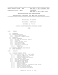
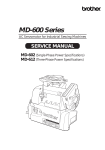
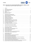
Verkaufskühlmöbel „Gefrieren/Kühlen” AHT Cooling Systems GmbH Verkaufskühlmöbel „Gefrieren/Kühlen” Typ B823, B823B, B823N PARIS 145 AD, VS Refrigerated Display Cabinet „Freezing/Cooling“ PARIS 175 AD, VS Typ B824, B824B, B824N 145 AD, VS PARIS 185 Typ B824, B823, B824B, B823B, B824N B823N PARIS 210 175 AD, VS B824, B829B, B824B, B825N B824N Typ B829, PARIS 250 185 AD, VS Typ B826, B824, B826B, B824B, B826N B824N PARIS 210 AD, VS Typ B829, B829B, B825N PARIS 250 AD, VS ATHEN 175 AD, VS Typ B826, B826B, B826N Typ B842, B842B, B842N ATHEN 210 AD, VS Typ B844, B844B, B844N ATHEN 175 AD, VS Typ B842, B842B, B842N ATHEN XL 210175 AD,AD, VS VS Typ B843, B844, B843B, B844B, B843N B844N ATHEN XL 207-7 AD, VS Typ B846, B846B, B846N ATHEN XL 210 175 AD, VS B843, B845B, B843B, B845N B843N Typ B845, ATHEN XL 207-7 AD, VS Typ B846, B846B, B846N ATHEN XL 210 AD, VS OSLO 210 AD Typ B845, B845B, B845N Typ B610, B610B MALTA 145AD AD, VS OSLO 210 Typ B822, B610, B822B, B610B B822N MALTA 185 AD, VS Typ B828, B828B, B828N MALTA 145 AD, VS Typ B822, B822B, B822N BOSTON 210AD, AD, VS MALTA 185 VS Typ B848, B828, B848B, B828B, B848N B828N BOSTON 210 AD, VS Typ B848, B848B, B848N 1 1 AHT Cooling Systems GmbH LIST OF CONTENTS AHT Cooling Systems GmbH 1 GeneralSystems specifications........................................................................................................................................... 13 AHT Cooling GmbH 2 Ratings plate and serial number ........................................................................................................................... 13 LIST OF CONTENTS 3 Application............................................................................................................................................................. 13 14 General specifications...........................................................................................................................................14 Unpacking and handling ....................................................................................................................................... 13 Bei zu warmer Innentemperatur: x 1 General specifications........................................................................................................................................... tun wenn ... number............................................................................................................................14 215 Was Ratings plate and serial 5 Set up .................................................................................................................................................................... Ratings plate and serial number ........................................................................................................................... 13 i Waren die Deckel lange Zeit offen? 32 Application. ............................................................................................................................................................14 6 Connecting to the electrical supply ....................................................................................................................... 14 3 Application............................................................................................................................................................. 13 4 Unpacking and handling........................................................................................................................................14 i Wurde versehentlich warme Ware eingelagert? 14 ACHTUNG: Arbeiten an der elektrischen Anlage und am 6.1 Internal lighting...................................................................................................................................................... 4 Unpacking and handling ....................................................................................................................................... 13 5 Set up....................................................................................................................................................................14 von Fachkräften durchgeführt i Hatten Sie vorher einen längeren Ausfall der 6.2 Power supply details ............................................................................................................................................. 14 5 Set up dürfen .................................................................................................................................................................... 13 6Kältesystem Connecting to nur the electrical supply........................................................................................................................15 werden. 7 Using the cabinet the firstsupply time and function.................................................................................................... 15 Spannungsversorgung? 6 Internal Connecting to the for electrical ....................................................................................................................... 14 6.1 lighting......................................................................................................................................................15 8 Operating the (-)AHT AD cabinets ............................................................................................................................... 15 6.2 Power supply 6.1 Gerät Internal lighting...................................................................................................................................................... 14 Das wurde imdetails.............................................................................................................................................15 - Prüfzentrum sorgfältig auf 7Leistung Using cabinet for theSollte first time and einmal function....................................................................................................16 8.1 CAREL electronic temperature control unit .......................................................................................................... 15 6.2 Power supply details ............................................................................................................................................. 14 und the Sicherheit geprüft. trotzdem eine Beruht die Störung auf keiner dieser Ursachen rufen Sie bitte 8Störung Operating the (-) AD .time ..............................................................................................................................16 8.2 Electronic temperature unitand AHT 601........................................................................................................ 16 auftreten, überprüfen Sie bitte folgendes: 7 Using the cabinet forcabinets. thecontrol firstzunächst function.................................................................................................... 15 Ihren Kundendienst. 8.1 Electronic temperature control............................................................................................................................... unit control AHT x01 (°C, °F)............................................................................................16 8.3 DANFOSS electronic temperature unit ..................................................................................................... 18 8 Operating the (-) AD cabinets 15 Ist der Netzstecker eingesteckt? x 8.2 (DANFOSS) electronic temperature control unit......................................................................................18 Falls eine Störmeldung auftritt, rufen Sie bitte Ihren 9 Temperature adjustment and control system ....................................................................................................... 19 8.1 SECOP CAREL electronic temperature control unit .......................................................................................................... 15 9x Temperature adjustment and control Liegt Spannung an..................................................................................................................................................... der Steckdose an? system........................................................................................................19 Kundendienst. 9.1 Warning device 20 8.2 Warning Electronic temperature control unit AHT 601........................................................................................................ 16 9.1 device. .....................................................................................................................................................20 x Ist beim electronic Gerät die Taste „/Aux“ oder 10 Maintenance, defrosting and cleaning .................................................................................................................. 20 8.3 DANFOSS temperature control unit ..................................................................................................... 18 10 Maintenance, defrosting and cleaning...................................................................................................................20 „Standby/Reset“ gedrückt worden? 10.1 Maintenance.......................................................................................................................................................... 20 9 Temperature.........................................................................................................................................................20 adjustment and control system ....................................................................................................... 19 10.1 Maintenance. 10.2 Defrosting instructions .......................................................................................................................................... 20 9.1 Defrosting Warning device ..................................................................................................................................................... 10.2 instructions. ..........................................................................................................................................20 10.3 Cleaning ................................................................................................................................................................ 10 Cleaning................................................................................................................................................................20 Maintenance, defrosting and cleaning .................................................................................................................. 20 10.3 11 Replacing the tube ................................................................................................................................................ 21 11 Replacing the tube................................................................................................................................................21 10.1 Maintenance.......................................................................................................................................................... 20 11.1 with fluorescent tubes.........................................................................................................................21 12 Taking the instructions cabinet out of operation for a period of time ....................................................................................... 21 10.2 Appliances Defrosting .......................................................................................................................................... 20 11.2 with LED strips....................................................................................................................................21 13 Disposal ................................................................................................................................................................ 21 10.3 Appliances Cleaning 20 12 the cabinet of operation for a period of time........................................................................................21 14 Accessories........................................................................................................................................................... 11 Taking Replacing the tubeout ................................................................................................................................................ 21 13 ................................................................................................................................................................21 15 What do, if ... ..................................................................................................................................................... 22 12 Disposal. Takingtothe cabinet out of operation for a period of time ....................................................................................... 21 14 Accessories...........................................................................................................................................................21 16 Circuit diagram .............................................................................................................................................292-297 13 Disposal ................................................................................................................................................................ 21 15 What to do, if.........................................................................................................................................................22 17 Circuit diagram light .....................................................................................................................................298-299 14 Accessories........................................................................................................................................................... 21 16 Circuit diagram...........................................................................................................................................268 - 279 18 Declaration of conformity .............................................................................................................................300-308 15 Declaration What to do, of if ... ..................................................................................................................................................... 22 17 conformity. ...........................................................................................................................280 - 288 16 Circuit diagram .............................................................................................................................................292-297 Safety instructions 17 Circuit diagram light .....................................................................................................................................298-299 18 Please Declaration of conformity .............................................................................................................................300-308 read these operating and maintenance instructions through carefully and also pass them on to other x people who are entrusted with handling and using this cabinet. Safety instructions x Check the cabinet for transport damage immediately after delivery. Please readmay these operating instructions through carefully also pass them on to to other x only be used and in themaintenance position in which it is to be operated (level, and horizontal with the opening the x The cabinet people who are entrusted with handling and using this cabinet. top). (Please observe the instructions for set up.) x the cabinet forfor transport damage immediately after delivery. x Check The cabinet is used the storage of foods that have already been chilled or frozen. Therefore any other use is Theconsidered cabinet may only be used in the position in which it is to be operated x not as use as intended. Freezers may only be operated with the(level, lid on.horizontal with the opening to the top). (Please observe the instructions for set up.) x The cabinet starts to work as soon as the operating voltage is switched on. Observe the ratings on the rating plate x and The the cabinet is used the storage foods that have already chilled frozen. other use is relevant localfor regulations forof electrical safety before youbeen connect the or cabinet to Therefore the power any supply. not considered as use as intended. Freezers may only be operated with the lid on. x In all effective refrigeration condensation water is precipitated or the moisture held in the air is frozen onto x refrigerated The cabinet surfaces. starts to work as soon as thetherefore operatingdefrost voltage is cabinet switched on. Observe the ratings on the rating plate The operator must the regularly. and the relevant local regulations for electrical safety before you connect thetocabinet the power direct to sunlight and supply. do not use any x Do not heat the cabinet over 70°C (158°F). Do not expose the cabinet In all effective refrigeration condensation water is precipitated or the moisture held in the air is frozen x heaters or sharp objects when defrosting. Do not spray high pressure cleaners or steam jet cleaners intoonto the refrigerated surfaces. The operator must therefore defrost the cabinet regularly. machine space. notobjects heat the 70°C (158°F). Do break not expose thelid cabinet direct sunlight and do not use any x x Do Sharp cancabinet scratchover and as a consequence the glass (singletopane safety glass). heaters or sharp objects when defrosting. Do not spray high pressure cleaners or steam jet engineers. cleaners into the x Work on the electrical system and the refrigeration system may only be undertaken by qualified Before machine space. unscrewing the machine space cover, the mains plug must be disconnected. x Sharp objects scratch andinterior as a consequence glass Before lid (single pane safety x ATTENTION: can Cabinets with lights have 2break mainsthe cables. working on theglass). electrical installation and x the Work on the electrical system and the refrigeration system may only be undertaken by qualified engineers. Before refrigeration system, both mains plugs must be disconnected. unscrewing the machine space please cover, the mains must beaccording disconnected. x When disposing of the cabinet, check yourplug obligations to the national WEEE regulations and take x the Cabinets with interior lights havePlease 2 mains cables. working on damaged the electrical ATTENTION: cabinet to the local WEEE disposal service. ensure thatBefore the pipes are not (do installation not drill intoand the the refrigeration system, both mains plugs must be disconnected. cabinet). x When disposing of the cabinet, your obligations according to the are national andintake x In order to maintain good food please quality,check it is recommended that frozen foods only WEEE put intoregulations the freezers the the cabinet to the local WEEE disposal service. Please ensure that the pipes are not damaged (do not drill into the period from 8:00 to 20:00 cabinet). operating staff must be instructed by the market manager. • The x In order to maintain good food it use is recommended that frozen foods are sensory only putorinto thefaculties, freezersinexpein the • People (including children) who are quality, not able to this unit safely because of their physical, mental periodorfrom 8:00 to 20:00 rience lack of knowledge should only do so under the supervision or instructions of an accountable person. Children in particular be supervised to ensure that they play manager. with the unit. The operating staff must be instructed by do thenot market • should canisters containing Àammable gasable propellants may stored in the unit. •Ɣ No People (including children) who are not to use this unitbesafely because of their physical, sensory or mental faculties, inexpeƔ No objects such as bottlesshould etc. may bedoplaced onthe topsupervision of the cooler. rience or lack of knowledge only so under or instructions of an accountable person. Children in particular Ɣ The unitbe must be regularly inspected removed from the goods display area. should supervised to ensure that and theyforeign do notbodies play with the unit. • Ɣ • Ɣ Ɣ • If the appliancecontaining should be damaged e.g.gas by shopping trolleys, this beunit. corrected by the store operator. ATTENTION! Risk of injury! No canisters Àammable propellants may bedamage storedmust in the Defrosting water or leakage from bottles not properly sealed may escape from the appliance. These must be cleared up without delay. 12 No objects such as bottles etc. may be placed on top of the cooler. Danger slip be regularly inspected and foreign bodies removed 12 The unitofmust from the goods display area. WARNING: if there is a power failure, the goods stacked must be checked by the store supervisor! 12 13 AHT Cooling Systems GmbH 1 General specifications Before installing and using this cabinet for the first time, the locally applicable regulations stipulated by trade law are to be observed. ATTENTION: In all effective refrigeration, condensation water is precipitated or the moisture held in the air is frozen onto the refrigerated surfaces. This build-up of ice is automatically defrosted by the (-) AD cabinets in regular cycles. AHT cabinets are free from PCB, PCT, asbestos, formaldehyde, cadmium and substances that interfere with wetness. The defrost water which accumulates is led via a drainage channel out of the inside of the cabinet into the machine space and evaporated. The refrigerant R404A (44% R125, 4% R134a, 52% R143a) is covered by the Kyoto Protocol and has a global warming potential (GWP) of 3784. The build-up of ice caused by any leaks in the defrosting drainage channel does not affect the function of the cabinet. Airborne sound emissions of the units < 70 dB(A) In the event of loud noises and/or strong vibrations in the unit, contact a service technician. The weights of the units are given in the datasheets. They can be obtained from AHT. The function of the cabinets is not affected by bulges which may occur in operation. The built-in bars are required for the cabinet to function and must not be removed. The bars are required to distance the food from the wall of the evaporator during the defrosting process. The design of the individual cabinet types may vary. 2 Ratings plate and serial number ATTENTION: ATTENTION:The Themodels modelsBarcelona, Barcelona,Boston, BostonBerlin and Berlin and with double-glazed insulating glass (without withOslo double-glazed insulating glass (without capillary capillary tube/must valve)not mustbe notinstalled be installed at an altitude tube/ valve) at an altitudein in excess 2,000 metres(6,560 (6,560feet) feet)above abovesea sealevel. level. excess ofof 2,000 metres The specifications on the “rating plate" are to be observed for installation and maintenance. This plate can be found on the back of the cabinet. 4 Unpacking and handling The serial number, cabinet type and refrigerant can be found either on the rating plate or on the sticker affixed inside on the plastic frame at the back. ATTENTION: To protect the cooling unit from damage, the cabinet must only be transported and stored in the operating position. Non-observance results in the loss of the warranty. 3 Application AHT units are designed for storing pre-packaged, frozen foods which have already been frozen to the appropriate temperature and pre-packaged frozen ice cream or frozen ice cream stored in suitable containers. The cabinets are not suitable for freezing fresh products. Before the cabinet is unpacked and while it is being unpacked, inspect visually to determine if there is any transport damage. Please look for loose parts, dents, scratches, visible fluid losses, etc. Report any damage to AHT immediately. For the rest the AHT terms of business apply. ATTENTION: A use of the cabinet other than this or one which goes beyond this is considered as not as intended. Before disposing of the packaging material, please check it for any parts of the cabinet which have come loose. The storage of any type of bottles is considered to be improper use for freezers. There is a danger of injury from breakage. The Àawless condition of the refrigeration unit and its proper use must be monitored regularly by the instructed operating staff. To that effect, the units must be checked to make sure that products that have been stored there by third parties (improperly) are removed. 5 Set up x x A Detail „A“ x x B Detail „B“ Minimum distances for the cabinets Distance A = 0mm Distance B = 155mm / 100 mm 14 Set the cabinet up in a well-ventilated place and so that it is level. Refrigerating devices discharge the heat they have taken from the storage space into the ambient air. Therefore the air circulation around the cabinets should not be hindered. Observe minimum distance when assembling in blocks. (See diagram.) The areas in between must not be covered (Exception AHT cover or with AHT approval) In the case of individual cabinets keep a min. distance of 50 mm all round to neighbouring surfaces (e.g.: walls). AHT Cooling Systems GmbH x x x ATTENTION: Mains voltage and mains frequency must match the ratings given on the cabinet’s rating plate. Work on electrical systems may only be undertaken by qualified electricians. The relevant local safety regulations must be observed. Only thin film advertising stickers can be used. Do not fix thick, insulating materials on the outer walls. Avoid draughts and greater heat absorption at the installation site. Do not place cabinets in front of heaters and under air outlets. 6.1 Internal lighting Do not point spotlights into the cabinets. Avoid lighting with light bulbs as much as possible. Fluorescent lights give off less heat! Lighting is already incorporated into the cabinets with AHT cabinets with an internal light. An additional light socket must be available for each chest. No more than 8 internal lights may be connected to one electrical circuit. Any heat radiation into the storage cabinet leads to increased operating costs and can influence the cabinet’s performance. ATTENTION: If the mains cable or light Àex becomes damaged it has to be replaced by AHT or AHT customer service. This information must be taken as a suggestion. The electrical supply company regulations and VDE regulations for the relevant region must be noted and observed. Electrical work must only be carried out by a qualified professional. When using light fixtures these may sometimes be connected to each other using the sockets that are already integrated. In this case you will normally only need 1 - 2 additional sockets for the lighting. With the LAK model no more than 12 light fittings can be connected to 1 fuse, with the LAL model no more than 18 light fittings and with the LA-A model no more than 8 light fittings. No other consumer loads may be connected to these sockets. x x ATTENTION: You must ensure that no AHT cabinets are connected to the lighting circuit. x ATTENTION: Do not expose cabinet to direct sunlight. The cabinet must not be heated over 70°C (158°F). 6 Connecting to the electrical supply The cabinet is a plug-in compact cabinet. The power cable (white) is 175 m. long. With cabinets with an internal light the lighting cable (black or light grey, depending on the country) is 120 cm. long. Both cables are located at the back right of the cabinet and are marked when they are delivered (mains cable lighting cable). The connection cable for the lighting is marked with a sticker and is either black or grey (depending on the country). It is very sensible to mark the light sockets clearly to prevent them being confused with the cabinet connector plug (light grey cable). Otherwise there is the risk that the cabinets will be switched off when the supermarket lights are switched off. • Provide fuses (see technical data on Protect 16 withA (slow-acting) 16 A (surge-proof) fuse. (See technical x • x x • the USA 15 A) datarating on theplate).(for rating plate.) Power cables should have a have minimum cross-section of The supply cable should a minimum cross2.5 mm² (corresponds to USA 14 AWG). It is essential 2 section of 2.5 mm . 3-pole cables MUST be used. 5to use three-core wires. The use of a five-core cable is pole cables must not be used. prohibited. useofofextension extension cables or multiway The use leads or multiple socketsadaptors must be avoided as avoided far as possible. If this cannot be avoided, should be if possible. If this is unavoidable, the mustthehave a minimum cross-section of makecables sure that cables you use have a minimum 2 USA 14 AWG). 2.5 mm² (corresponds to cross-section of 2.5 mm . 6.2 Cabinets should only be connected to shockproof sockets with earth contact and their own mains circuit. No more than 2 cabinets should ever be connected to a circuit. With cabinets with additional flex for interior lighting only a maximum of 8 light flexes may be connected to a fuse. AHT recommends using a cable channel on the floor with sockets built into it or on top. The cable channel used must not be any higher than from the floor to the lower edge of the rear ventilation grid of the cabinet. Any other fixtures or superstructures (e.g. shelves with longitudinal supports above) that obstruct the dissipation of heat between the cabinets must be avoided. Should fittings between the cabinets be necessary anyway, written approval must be obtained from AHT for the relevant design. Power supply details An FI circuit breaker is provided to install AHT cabinets in the supermarket when the electrical installation is done. No more than 2 cabinets must be connected to a safety device like this. One safety device for each cabinet is preferable. 2 cabinets can be supplied for each safety device with a combination of a fuse and circuit breaker (LS/ FI circuit breaker). AHT strongly recommends use anLS/FI LS/FI combination usingofan for appliance (for USA a CB/GFI combination) with witheach C characteristic, 10A rated current and 30mA release current, type G surge for each cabinet. C characteristic, 10 Aprotection nominal current and 30 mA tripping Should this not beresistant“. acceptable, the following current, Typesuggestion G „surge current maximum specifications be acceptable, used: Should this suggestion must not be the following maximum specifications must be used: Fuse Fuse A safety fuse with a 16AAHT fuse appliances, with C characteristic For a circuit breaker with a 16 A (for USA must provided forCAHT 15 A) be characteristic fusecabinets. is to be provided. No more than 2 cabinets are permitted on 1 fuse. However, in order to achieve the highest possible operational safety, we suggest that each chest has its own fuse. FI circuit breakers It is strongly recommended that you use FI circuit breakers. You must ensure that the type G circuit breaker used is be surge-protected. We suggest that the circuit breaker has the following capacity: The sensor connection on the back of the cabinet must only be connected to a safety extra low voltage connection (SELV). 15 AHT Cooling Systems GmbH Rated current Release current 40A 30mA no more than 2 cabinets to 1 FI The cabinets must only be loaded up to the stacking lines. The storage temperature set cannot be guaranteed above the stacking line. As prescribed by VDE100-410 in its current version (issue dated June 2007) the use of a residual current circuit breaker (RCCB) as „additional protection for external areas and sockets“ (411.3.3) is compulsory (as it already is in Austria and Switzerland). ATTENTION: It is possible that defrosting water may escape from the unit. If this happens, it should be cleared up immediately to avoid the danger of a slippery Àoor. A separate safety fuse is appropriate for the lighting for AHT cabinets. Load dropping switches or cabinet cut off switches are not permitted because malfunctions could occur as a result. Should these safety guidelines not be observed claims under the guarantee and/or for damages will not be entertained. ATTENTION: It is not permitted to operate the cabinets without a lid or with the lid open. All cabinets are equipped with glass lids as standard. The lids are required for the correct operation of the cabinet. They should only be opened for loading and unloading the food. 7 Using the cabinet for the first time and function Before being used for the first time (after installation – see section 5) the cabinet should have a minimum temperature of +16°C (60.8°F), otherwise the cabinet must be adjusted to normal room temperature. ATTENTION: When the operating voltage is switched on (plug in mains plug – see section 6) the cooling unit starts to work straightaway. 8 Operating the (-) AD cabinets Despite the automatic de-icing, it is recommended for hygiene reasons that the cabinet is completely defrosted once or twice a year so that any ice build-up can be removed and the cabinet interior can be cleaned. 8.1 CAREL electronic temperature 8.2 Electronic Electronic temperature control unit temperature control unitcontrol 8.1 unit AHT 601 (°C), 701 (°F), 801 (°C), 901 (°F) x01 (°C, °F) AHT 601 The CAREL electronic temperature control unit controls electronic temperature controlIn unit AHT601/701/801/901 601 designed Thetemperature electronic temperature control unit AHT electronic control unit x01 the intemperature the cabinets. addition theisAHT automatic to designed control AHTregulate refrigerators freezers with is to regulate control and AHT and refrigerators and de-icing is and initiated in regular cycles. freezers with automatic can both be used automatic de-icing. Thede-icing. control The unitcontrol can beunit used for Before for theand firstfor time, correctnessIfIfand both foroperating standalone operation and forcheck block installations. the standalone operation block installations. contact cable connections and thebe voltage supply cabinetsofareallinstalled in a block, they must linked via bus one more time. cables. Instructions on cabling and address assignment are given under section “Selecting the bus addresses”. Operation After operating for roughly 1 to 2 hours the desired interior temperature is reached (see section 9 - Recommended storage temperatures). The pre-chilled chilled food can be put in. ATTENTION: Do not stand on or put loads on the glass lid. Before operating the first time, correctness All operation and for adjustment of thecheck cabinet is carried and out contact all cable connections supply via the of control panel. You can and get the to voltage all necessary one more and time.settings by a few presses of the buttons. functions The three figure display (7 segment display) with extra Operation symbols provides you with all necessary information. The temperature is displayed by means of red LEDs in a 7 segment display, in which the value is displayed in 3 figures. There are 4 buttons available as controls, which are assigned as follows: The glass lids are not intended as aids for reaching the upper shelves or for storing miscellaneous objects and are not equipped for such loads. The (-) AD cabinets are set to a temperature of –19°C (-2°F) in the factory. How to change the temperature value is described in section 8. The cabinet has automatic de-icing. The cabinet's de-icing times are pre-set in the control unit. De-icing is automatically initiated twice a week during the night. Deicing can also be initiated manually. Manual initiation of deicing is described in section 8. The cabinets have a real time clock, which ensures that de-icing starts correctly during the night. The time on the clock is pre-set in the AHT factory. If the cabinets are not operated for longer than 6 months, it is possible that the time on the clock needs to be re-set. (This is discernible if the cabinets defrost during shop opening hours.) This means that the frost or ice build-up in the inner container is defrosted and the ensuing water is fed away via the discharge channel. Should you notice that your cabinet is defrosting during opening hours, please call a service engineer to re-set the clock on the control unit correctly. The food does not come to any harm during de-icing. The temperatures stipulated by the standard are not exceeded. In order to maintain good food quality, it is recommended that frozen foods are only put into the freezers in the period from 8:00 to 20:00 PRG/mute Ÿ/aux “+” button … The button-isbutton used to select the enabled Man. Defrost / Set - button Plus-button required values, to assign addresses and to select the Minus-button Standby-button parameter levels. “-” button … The button is used to select the enabled required values, to assign addresses and to select the parameter levels. Fig. x01(°C); (°C, °F) Fig. AHT AHT 601 “MAN. DEFROST / SET” AHT 701 the same but display in °F button … To activate a Set - button def/ź manual defrost, after which a 24 hour block is set until the next deicing, i.e. after this is activated …is The button switches off the “PRG/mute” no further manualbutton defrosting possible for 24 hours. acoustic alarm (buzzer) and deactivates the alarm relay. “STANDBY” button switched onon and off off “STANDBY” button… …The Thecontrol controlunit unitcan canbebe switched and button …This Theswitches required cancontrol be selected using “Set” using this button. the AHT unit using button. This switches thevalue AHT601 x01 control unitonly onlyon ontoto “Stand By”. and then altered with the appropriate buttons. “Stand By”. this button “Ÿ/aux” button … Button is used to increase the required value. “def/ź” button … Button is used to reduce the required value and to activate de-icing manually. 16 AHT Cooling Systems GmbH button the … To activate a manual “MAN. DEFROST SET” General information/ on operating buttons: defrost, after which a 24 hour block is set until the next deButtons must be continuously for longer than icing, i.e. after thispressed is activated no further manual 0.5 seconds to get a reaction defrosting is possible for 24 hours. If a button is not actuated for 10 seconds, the display … value” The control unit can be switched “STANDBY” goes back button to “actual on off using button.immediately, This switches theare AHT 601 Set values arethis accepted if they valid and control unit only on to “Stand By”. 4) If A5 is selected, the required value can be freely set by the user. To be more precise, with the “MAN. DEFROST / SET” button held down, the required value can be freely set between -30°C and +15°C using “+” or “-”. The required setting corresponds to the product temperature at the loading limit when the cabinet is fully loaded. General information on operating the buttons: 5) The return to the actual temperature display / actual value happens after 10 seconds. Buttons be pressed Setting a must required valuecontinuously for longer than 0.5 seconds to get a reaction The in whichforthe is to work can a button is range not actuated 10cabinet seconds, the display Iftemperature be selected by to the following parameters. goes back “actual value” Set values are accepted immediately, if they are valid Parameter Function Required temperature on LL 6) The value set is accepted immediately after the return to the actual value. Selecting the bus address The control unit is delivered with the bus address 0, which corresponds to a standalone cabinet. Setting a required value A1 Deep freezing (required value 1) -18°C The range in which the cabinet is to-20°C work can A2 temperature Deep freezing (required value 2) be selected by the following parameters. A3 Meat refrigeration +1°C A4 Plus cooling +4°C Parameter Function Required temperature on LL A5 Free parameter -18°C (can be set by customer) A1 Deep (required 1) -18°C Settingfreezing range from -30°Cvalue to +15°C A2 Deep freezing (required value 2) -20°C No hasrefrigeration to be set, just the control +1°C range A1, A3 temperature Meat A2, A4 A3, A4 or A5. Plus cooling +4°C A5 Free parameter -18°C Depending on customer requirements, the different control (can be set by customer) ranges can be blocked or enabled. Setting range from -30°C to +15°C When setting values, selections canrange only A1, be No temperaturerequired has to be set, just the control made within those control ranges that have been enabled. A2, A3, A4 or A5. If nothing different is requested by the customer, the Depending on customer requirements, the different control following parameters are enabled: ranges can be blocked or enabled. In this condition (address 00) the cabinets and control units are not registered in the bus system. To identify cabinets in the bus system the addresses, from 01 to a maximum of 48, must be assigned. Before assignment the cabinets must be networked with a 6-core cable (bus cable). The last one in the group must be fitted with a terminal resistance. Then we recommend that the addresses are entered in the sequence of the actual wiring order. The address 01 is essential as energy management and control of the automatic de-icing takes place via this address. Procedure for address assignment: 1) Press the buttons “+” and “-” at the same time for at least 5 seconds. x setting Freezer: A1 When required values, selections can only be made within those control ranges that have been enabled. x Meat cabinet: A3 If nothing different is requested by the customer, the x Switchable A1 and A3 following parameterscabinet: are enabled: x 2) In the display “Adr.” appears (about 0.5 seconds) and alternately the current bus address e.g. “00” (for 2 seconds). 3) If the “+” button is now pressed (for at least 0.5 Freezer: A1 seconds), the next free address on the bus can be assigned. By pressing once and assigning the first address “01”, it would appear in the display. If too high an address was assigned, the current address can be reduced with the “-” button (for 0.5 seconds at least), e.g. from “02” to “01”. x Meat cabinet: A3 Selecting the enabled required value x Switchable cabinet: A1 and A3 The control unit is delivered with the required values Selectingaccording the enabled valuetype. Another required enabled to required the cabinet value can be selected as follows: The control unit is delivered with the required values enabled cabinet type. required 1) Pressaccording the “+” orto“-”thebutton for at leastAnother 1 second. value can be selected as follows: 2) Then “STP” appears (for about 0.5 seconds) and 1) alternately Press the “+” for atvalue leaste.g. 1 second. “-” button theorcurrent required “A1” (for 2 seconds). 2) Then “STP” appears (for about 0.5 seconds) and required value e.g. “A1” 2 3) alternately If the “+” the or current is now pressed, the (for next “-” button seconds). enabled required value can be selected. The selection must be made within 10 seconds, otherwise the display 3) If the “+” or “-” button is now pressed, the next automatically goes back to the actual value. enabled required value can be selected. The selection must be made 10 seconds, ATTENTION: withwithin the (U) series: ifotherwise a switchthe isdisplay made automatically to A1, the actual value. required from A1 to A3 orgoes fromback A3 to the cabinet’s temperature Either fromif –18°C to is +1°C or ATTENTION: changes. with the (U) series: a switch made from +1°C to -18°C! from A1 to A3 or from A3 to A1, the cabinet’s required temperature changes. Either from –18°C to +1°C or from +1°C to -18°C! 4) After 10 seconds the value is accepted and changed to the actual value. 5) For the subsequent cabinets assign the addresses exactly as described in points 1 to 4, always selecting the next free address, e.g. “02” De-icing In addition to the automatic de-icing, a manual de-icing cycle can also be initiated. To do this, the “MAN. DEFROST/SET” button must be pressed briefly. “- d -” appears in the display for about 2 seconds and then “dFr.” is displayed. De-icing is now active. It takes around 10 mins. until the ice on the inner wall of the container starts to melt, beginning at the top. After the de-icing cycle has run, the cabinet returns to normal operation. The display then changes from “dFr.” to the temperature display. 17 AHT Cooling Systems GmbH After every de-icing cycle the manual initiation of de-icing is blocked for 24 hours. De-icing cannot be manually initiated during this time. If the cabinet does not react to the “MAN. DEFROST/SET” button being pressed, the cabinet has probably been defrosted during the night on the time controller. While the button is being pressed “- - -” is displayed in the 7 segment display. Operation Once the voltage has been switched on, the cabinet starts automatically. During normal operation the cabinet’s average interior temperature is displayed in °C. If you press the "Standby / Reset" button for at least 1 second the cabinet will switch to standby mode. The display shows: "- - -". If you press the "Standby / Reset" button once more the cabinet will switch on again and the internal temperature will be displayed. This procedure may take a few seconds. Despite the automatic de-icing, it is recommended for hygiene reasons that the cabinet is completely defrosted once or twice a year so that any ice build-up can be removed and the cabinet interior can be cleaned. Defrost start times with networking via bus Defrosting is performed according to the factory setting, beginning at 21:30. The defrosting day is allocated to a group depending on the bus address and automatically calculated by the control unit. This prevents all cabinets de-icing at the same time. The de-icing cycles are scheduled at 3 day intervals. +/- - Button ٻ ٻڋډڔڌڈ Handling alarms and cancelling alarms In the event of an error, the following is displayed in the 7 segment display. After an error has occurred, the actual value flashes alternately with the error message. In the case of excessive temperature, only the actual value flashes. After a few minutes only a dot below the actual value continues to flash. And every hour the current error message is displayed again. The error messages are listed below: Actual value/Bus Bus error, missing address Actual value/Col. Address collision Actual value/F1 Sensor error, F1 Actual value/F2. Sensor error, F2 Actual value/F3 Sensor error, F3 Actual value/d.Fr./F3 Defrosting system error Actual value/Clock Time/Date not valid Actual value /EE Data fault STANDBY/RESET button “+/-” button … Selection of the temperature range (parameter) and address assignment. “MAN. DEFROST” button … Manual initiation of the deicing process. “STANDBY/RESET” button … Main switch for switching to “Stand By” (from normal operation) and for cancelling the alarm (when there is an alarm). Setting a required value The temperature range in which the cabinet is to work can be selected by the following parameters. Parameter Function Required temperature on LL A1 Deep freezing (required value 1) -18°C (0°F) A2 Deep freezing (required value 2) -20°C (-4°F) A3 Meat refrigeration +1°C (+33.8°F) A4 Plus cooling +4°C (+39.4°F) A5 Free parameter -18°C (0°F) (can be set by the customer) Setting range from -30°C (-22°F) to +15°C (+59°F) Flashing actual value Excessive temperature alarm Once an error has been remedied, the error message goes out automatically. Switching on/off using the STANDBY button, (see section Switching the control unit on and off), can be used to cancel the error message. If the error is still active, the current error message is displayed again. No temperature has to be set, just the control range A1, A2, A3 or A4. 8.2 (DANFOSS) electronic 8.3 SECOP DANFOSS electronic temperature temperature control unitcontrol unit Depending on customer requirements, the different control ranges can be blocked or enabled. When setting required values, selections can only be made within those control ranges which have been enabled. The DANFOSS electronic temperature control unit is designed to control and regulate AHT refrigerators and freezers with automatic de-icing. The control unit can be used both for standalone operation and for cabinets with bus networking. The start times for the automatic de-icing are set in the factory. De-icing takes place during the night. If nothing different is requested by the customer, the following parameters are enabled: Freezer: A1 Before operating for the first time, check correctness and contact of all cable connections and the voltage supply one more time. Meat cabinet: A3 Switchable cabinet: A1 and A3 18 AHT Cooling Systems GmbH ATTENTION: When there is no alarm, a brief press of the “Stand By / Reset” button switches the cabinet off (display “- - -”). Selecting the enabled required value The required value can be selected by pressing the “+/-” button briefly. The currently set parameter appears (e. g. A1). Pressing the “+/-” button briefly again selects the next required value, e.g.: A2. When all enabled parameters have been gone through, A1 is displayed again. Setting automatically accepted 5 seconds after the last button depression. Error code table: F1, F2, (F3), F4 Clock E20 E21 E70 ATTENTION: with the (U) series: if a switch is made from A1 to A3 or from A3 to A1, the cabinet’s required temperature changes. Either from –18°C to +1°C or from +1°C to -18°C! E75 E99 Err Selecting the bus address To identify cabinets in the bus system the addresses from 01 upwards must be assigned. Before assignment the cabinets must be networked with an appropriate bus cable. The last one in the group must be fitted with a terminal resistance. Then we recommend that the addresses are entered in the sequence of the actual wiring order. After every de-icing cycle the manual initiation of de-icing is blocked for 24 hours. De-icing cannot be manually initiated during this time. If the “MAN. DEFROST” button were to be pressed during this time, then the display would change again to the operating display. If the cabinet does not react to the “MAN. DEFROST” button being pressed, the cabinet has probably been defrosted during the night on the time controller. Despite the automatic de-icing, it is recommended for hygiene reasons that the cabinet is completely defrosted once or twice a year so that any ice build-up can be removed and the cabinet interior can be cleaned. Procedure for address assignment: 2) Press the “+/-” button 3 times within 1.5 seconds. “Adr.” display alternates with the address number. With the first cabinet “ADR” would now appear alternately with “OFF” in the display. 3) If the “+/-” button is now pressed, the next free address on the bus can be assigned. Press once and the next free address appears. 9 Temperature adjustment and control system Brief press of the “+/-” button, single jump to the next higher bus address. Long press of the “+/-” button, fast “continuous ATTENTION: Observe the stipulated for your products! After 5 seconds the value is accepted and “- - -” appears in the display. The control unit must be switched on using the “STAND BY/RESET” button. x x x x x x run through” of the bus addresses. Runs through the loop from OFF to the maximum address. 4) Compressor error and all other errors MMI (no communication with system) In addition to the automatic de-icing, a manual de-icing cycle can also be initiated. To do this, the “MAN. DEFROST” button must be pressed briefly. “DEF” appears in the display and the manual de-icing starts. It takes around 10 mins. until the ice on the inner wall of the container starts to melt, beginning at the top. After the deicing cycle has run, the cabinet returns to normal operation. The display then changes from “DEF” to the temperature display. In this condition (OFF) the cabinets and control units are not registered in the bus system. Press the “STAND BY/RESET” button. “- - -” appears in the display, cabinet is switched off. Excessive electronic system temperature De-icing The control units are delivered with the bus address 0. “OFF” is displayed as the bus address. 1) Sensor failure (floor=1, air=2, condenser sensor=4) Battery dead Temperature alarm Excessive temperature on F4 Electronic error storage temperatures Recommended storage temperatures are: Frozen foods: -18°C (0°F) Ice cream: -20°C (-4°F) Minced meat: +1°C (+33.8F) Milk products: +6°C (+42.8°C) Fresh milk: +4°C (+39.2°F) Fruit/Vegetables: +6 / +12°C (+42.8°F / +53.6°F) 5) For the subsequent cabinets assign the addresses exactly as described in points 1 to 4, always selecting the next free address. Alarm and Alarm Reset Please ensure that the products being stored are stored at the required temperature. An alarm is shown by the display of an error message. This error code is displayed alternately with the temperature (flashing display). In addition there is the option of emitting an acoustic signal from a buzzer (built-in as an extra). The temperature display shows a system temperature, which bears no direct relationship with the product temperature. The sensor is positioned on the floor of the cabinet under the floor panel. Depending on the turnover of goods, displays of as low as -25°C (-13°F) are possible. Even if colder temperatures are displayed, this does not mean that the cabinet is set at too cold a temperature, as the product temperature at the loading limit is clearly warmer than at floor level. One short press of the "Stand By / Reset" button. A single press of the “Stand By / Reset” button cancels the acoustic alarm (if connected) and the error code is no longer displayed in the display. A red dot remains in front of the “Tool” symbol in the display. 19 AHT Cooling Systems GmbH 9.1 Warning device As an option the cabinets are equipped with a socket connection so that an external warning device can be added on. This can be found on the back of the (-) AD cabinets. The potential-free contacts can be loaded with a protective extra low voltage of max. 24 V/2 A. If the permitted deviation from the required temperature set is exceeded (warmer), the contact pair 3 and 6 closes and the contact pair 3 and 5 opens. 3 2 1 AHT Cooling Systems GmbH 6 4 5 9.1 10 Pin assignment of the socket for the warning device (view Warning device from the rear of the cabinet). A suitable plug can be obtained as an the accessory. As an option cabinets are equipped with a socket connection so that an external about warning device can be You can get further information additional remote added on. This can be found on the back of the (-) AD monitoring options from your dealer. cabinets. The potential-free contacts can be loaded with a protective extra low voltage of max. 24 V/2 A. If the permitted deviation from the required temperature Maintenance, defrosting and set is exceeded (warmer), the contact pair 3 and 6 closes and cleaning the contact pair 3 and 5 opens. 10.1 Maintenance 3 2 1 ATTENTION: Do not heat cabinets over 70°C (158°F) and6do not 4 to excessive heat (radiant heaters, 5 expose etc.) Pin of are the essentially socket for the warning device (view The cabinets maintenance-free. x assignment from the rear of the cabinet). A suitable plug can be There discharge channel on the cabinet’s inner x obtained as is anaaccessory. container for the defrost water which accumulates You can getautomatic further information about additional remote during de-icing. Any contamination of this monitoring options from your discharge channel must dealer. always be cleared. 10.2 Defrosting instructions 10 Maintenance, defrosting and For units with automatic defrost (AD): If water appears uncleaning der the unit after defrosting, check the seal tightness of the defrosting tray. 10.1 Maintenance (-) AD cabinets are fitted with an automatic defrosting ATTENTION: Do notthat heat cabinets overof70°C (158°F) system. This ensures only a fine layer ice can form abovedothe drain channel. This is removed twice a heaters, week by and not expose to excessive heat (radiant the automatic defrosting system. However, should it be etc.) necessary to defrost the cabinet, this can be done by The cabinets are essentially maintenance-free. x pressing the " /def" or „MAN. DEFROST" button. This will start There the automatic defrosting cycle.onWhen the cycleinner has is a discharge channel the cabinet’s x endedcontainer the cabinet to normal operation. forreturns the defrost water which accumulates during automatic de-icing. Any contamination of this After each defrosting cycle it is not possible to defrost discharge channel must always be cleared. manually for 24 hours. During this time the defrosting cannot beinstructions started manually. If the cabinet does not 10.2process Defrosting respond to pressing the " /def" or "MAN. DEFROST" For units (AD):aIf water appears unbutton it with has automatic probably defrost undergone scheduled defrost der the unit after defrosting, check the seal tightness of the process during the night. defrosting tray. Although automatic defrosting is recommended, completely (-) AD the cabinets areonce fittedor with defrosting defrost cabinet twiceana automatic year to remove the system. This that to only a fine form remaining ice ensures build up and clean the layer insideofof ice the can cabinet. above the drain channel. This is removed twice a week by automatic defrosting system. However, should it be 10.3 the Cleaning necessary to defrost the cabinet, this can be done by WARNING: cleaning the appliance (except pressing thewhen " Do/def" or use „MAN. DEFROST" Thisfor will ATTENTION: not sharp objectsbutton. or tools to the glass panes in the lid), do not use any commercial start theorautomatic When the cycle scratch chip offdefrosting the ice cycle. or frost layer! Risk has of cleaning The appliance only to be cleaned ended theagents. cabinet returns to normalisoperation. damaging the inner walls! with a dry cloth. After each defrosting cycle it is not possible to defrost manually for 24 hours. During this time the defrosting 20 process cannot be started manually. If the cabinet does not respond to pressing the " /def" or "MAN. DEFROST" button it has probably undergone a scheduled defrost process during the night. above the drain channel. This is removed twice a week by the automatic defrosting system. However, should it be necessary to defrost the cabinet, this can be done by pressing the " /def" or „MAN. DEFROST" button. This will start the automatic defrosting cycle. When the cycle has ended the cabinet returns to normal operation. After defrosting cycle it is not possible to defrost Do noteach highto pressure (e.g. steam jet • Use aspray dry cloth wipe downcleaners the outside of the casing manually into for the 24 machine hours. During this time thespace. defrosting cleaners) space and storage from time to time process cannot be started manually. If the cabinet does not • Clean the panes ofcabinets glass with a standard window Moveto food to other x respond pressing the " /def" or "MAN. DEFROST" cleaning agent button it has probably undergone a scheduled defrost xprocess Switch the cabinet off by pressing the "/Aux" or during the night. "Standby/Reset" button for about 1 second WARNING: since window-cleaning agents contain a Although defrosting is recommended, proportion solvent, with plastic completely surfaces Openautomatic orofremove lid contact x defrost be the avoided. cabinet once or particular twice a year to removethat the should It is of importance Let cabinet defrost x remaining ice build up and to clean the inside the on cabinet. no window-cleaning agent residues are ofleft any plastic components. Remove the bars out of the cabinet x 10.3 Cleaning x Clean the channel with a wet sponge or cloth and remove any of contamination ATTENTION: Doparticles not use sharp objects or tools to scratch or chip off the ice or frost layer! Risk of ATTENTION: The channel must not be cleaned with damaging the inner walls! anything pointed or sharp. Do not spray high pressure cleaners (e.g. steam jet 20 Suck out defrosted water using a wet vacuum x cleaners) intoor thedry machine spacean andabsorbent storage space. cleaner out using cloth or sponge. food to other cabinets x Move Wipe cabinet dry, so off cleaning inner chamber x Switch the cabinet by pressing the "/Aux" or "Standby/Reset" button for about 1 second x Switch the cabinet on by pressing the "/Aux" or for about 1 second Open or remove lid x "Standby/Reset" lid, leave cabinet to chill for 1 to 2 hours and x Close Let cabinet defrost put food back in again x Remove the bars out of the cabinet To remove particles of contamination from the channel, it is Clean the channeldividers with a and wet side sponge and x also possible to remove partsorofcloth the bars. particles of contamination Front remove wall andany back wall can then be folded down into the centre of the cabinet, makingmust the channel for ATTENTION: The channel not be accessible cleaned with cleaning is recommended that a manual deanythingpurposes. pointed orItsharp. icing is initiated before cleaning the channel. out defrosted water using a wet vacuum x Wipe theoroutside housing to time cloth using or a x Suck cleaner dry out usingfrom an time absorbent dry cloth sponge. x the panes of glassinner using commercially Wipe cabinet dry, so cleaning chamber x Clean available window cleaner x Switch the cabinet on by pressing the "/Aux" or ATTENTION: The glass lids1 second are made of special "Standby/Reset" for about hardened and heat-reflecting vaporised glass. There is Closelubricant lid, leaveincabinet to chill for 1Totokeep 2 hours and x a special the sliding frame. the lids putproperly, food backyou in again sliding should clean dirt and dust from the frame every nowofand again. To remove particles contamination from the channel, it is also possible to remove dividers and side parts of the bars. If the glass cover is very dirty: Front wall and back wall can then be folded down into the centre of the cabinet, making the channel accessible for x Unplug cleaning purposes. It is recommended that a manual deRemove cover and clean the glass frame inside x icing is initiatedthe before cleaning the channel. and out and in the corners and the cover handle with thecleaner. outside housing from time to time using a x Wipe a steam dry cloth x Dirt on and behind the water guard bar can be x Clean glass If using commercially removedthe withpanes a steamofcleaner. necessary the water available guard barwindow can be cleaner removed with a Torx screwdriver. Remove x ATTENTION: dirt the cover and of kickspecial plates Theonglass lids runners are made with aand steam cleaner too vaporised glass. There is hardened heat-reflecting a special lubricant Dry the cabinetin the sliding frame. To keep the lids x sliding properly, you should clean dirt and dust from Plug every in x the frame now and again. ATTENTION: The ventilation grid on the side and the If the glass cover is very dirty: alarm unit on the front of the cabinet must under no x Unplug circumstances come into contact with the steam cleaner. Danger fire. and clean the glass frame inside Remove theof cover x and activities out and inonthe corners and be theperformed cover handle with Cleaning the unit must exclusia steam cleaner. vely by instructed operating staff. There is a danger of injury from edges. unit models (U) and x sharp Dirt on and When behindcleaning the water guard bar can (S), be safetyremoved gloves must be used. with a steam cleaner. If necessary the water x x guard bar can be removed with a Torx screwdriver. Remove dirt on the cover runners and kick plates with a steam cleaner too Dry the cabinet defrosting If the glass cover is very dirty: can form x Unplug week by uld it be AHT Cooling Systems GmbH x Remove the cover and clean the glass frame inside done by and out and in the corners and the cover handle with This will Light a steam cleaner. ycle has Light cover cover x x Dirt on and behind the water guard bar can be 11 Replacing thea tube removed with steam cleaner. If necessary the water x o defrost guard bar can be removed with a Torx screwdriver. defrosting x Remove dirt on the cover runners and kick plates does not with a steam cleaner too EFROST" x d defrost x Dry the cabinet x x ompletely move the cabinet. Plug in ATTENTION: The ventilation grid on the side and the x alarm unit on the front of the cabinet must under no circumstances come into contact with the steam cleaner. Danger fire. ATTENTION: In of case of lamp breakage, remove all traces of glass carefully frommust the goods display exclusiarea Cleaning activities on the unit be performed ools to andby check over the goodsstaff. for glass vely instructed operating Theresplinters. is a danger of injury Risk of from sharp edges. When cleaning unit models (U) and (S), Specification of the tubes: safety gloves must be florescent used. AHT Cooling Systems (The cabinet typeGmbH can be seen from the rating plate) Remove the lighting cable (black or light grey). Loosen the light cover (transparent part) from the housing by pressing together lightly and remove. (See pictures.) Remove defective florescent tube. Replace with a new special florescent tube of the same type according to the specifications given below. Replace the light cover. 20 Light x Light cover cover PARIS 145 the tube 1 off 11 Replacing 11 Replacing the tube 11.1 Appliances with fluorescent tubes PARIS 175 / ATHEN 175 x 1 off PARIS 185 / ATHEN XL 175 PARIS 210 / MALTA 145 x 2 off x ATHEN 210 / ATHEN XL 210 ATHEN XL 207 / ATHEN XL 207-7 x Remove the lighting cable (black or light grey). Ø 16 x 1149 mm 28W T5 Loosen the light cover (transparent part) from the Ø housing 16 x 1449 mm 35Wlightly andT5remove. (See by pressing together pictures.) defective florescent tube. Ø Remove 16 x 849 mm 21W T5 Replace with a new special florescent tube of the same type according to the specifications given below. Replace the light cover. OSLO 210 / BOSTON 210 PARIS 250 /InMALTA 185 breakage, remove2 all off ATTENTION: case of lamp Ø 16 x 1149 mm traces of glass carefully from the goods display area and check over the goods for glass splinters. 12 Taking the cabinet out of Specificationfor of the operation a florescent periodtubes: of time ATTENTION: EPS insulation material Open lid, let cabinet come back to room temperature and PARIS 145 1 off clean. Ø 16 x 1 off Ø 16 x Leave lid open at least a crack (approx. 2-3 cm). Ventilation prevents PARIS smells and mould buildingXL up in the inner chamber. 185 / ATHEN 175 On no account expose to sunlight PARIS 210 cabinet / MALTA 145 with the lid closed. 2 off (Risk of damage due to high inside temperature) 21W T5 14 Accessories ATHEN 210 / ATHEN XL 210 There is a range of special accessories for the cabinets, such as e.g. x lighting sets x 1149 mm 28W dividing walls, adjusting shelves x Ø 16 impact and water protection bars x 11.2 Appliances with LED strips 12 Taking the cabinet out of de-icing. The food does not come to any harm during The temperatures stipulated by the standard are not exceeded. operation for a period of time The LED strips may only be replaced by an authorised This has also been confirmed by the TÜV. specialist. Please contact our AHT customer service centre Remove all food. or our Coolpoint partner! Open lid, let cabinet come back to room temperature and clean. Leave lid open at least a crack (approx. 2-3 cm). Ventilation prevents smells and mould building up in the inner chamber. If the cabinets are not used for longer than 6 months, it is possible that the time on the clock needs to be re-set. This Do not put the cabinet in the normal rubbish. Instead, please check your obligations accordingmm to the national WEEE regulations 1149 28W T5 and take the cabinet to the local WEEE disposal service. 1449 mmensure that 35W Please the pipes T5 are not damaged. Ø 16 x 849 mm If the cabinets are not used for longer than 6 months, it is XL on 207 ATHEN XLto207-7 possible ATHEN that the time the/ clock needs be re-set. This is the case if cabinets are defrosting during opening hours. OSLO 210 / BOSTON 210 Should you notice that your cabinet is defrosting during 250 /call MALTA 185engineer to re-set the 2 off opening PARIS hours, please a service clock on the control unit correctly. On no account expose cabinet to sunlight with the lid closed. (Risk of damage due to high inside temperature) T5 13 Disposal (The cabinet type can be seen from the rating plate) Remove all food. PARIS 175 / ATHEN 175 28W T5 13 Disposal For further information, please contact your supplier or dealer. ATTENTION: EPS insulation material Do not put the cabinet in the normal rubbish. Instead, please check your obligations according to the national WEEE regulations and take the cabinet to the local WEEE disposal service. Please ensure that the pipes are not damaged. 21 14 Accessories There is a range of special accessories for the cabinets, such ATHEN XL 207 / ATHEN XL 207-7 OSLO 210 / BOSTON 210 AHT Cooling Systems GmbH 185 PARIS 250 / MALTA 2 off Ø 16 x 1149 mm 12 Taking the cabinet out of forifa...period of time 15 operation What to do, 28W T5 13 If the inside temperature is too warm: x Disposal WARNING: insulating material is polyurethe lids open for insulation a long time?material i Were ATTENTION: EPS thane foam (PUR foam) with pentane! warm food put in by i Was Do not put the cabinetmistake? in the normal rubbish. Instead, please check obligations accor-to there previously beenyour a longish interruption i Has Remove all food.Work on the electrical system and the ATTENTION: refrigeration systemcome may only by qualified Open lid, let cabinet backbe to undertaken room temperature and engineers. clean. to the national WEEE regulations and take theding voltage supply? the cabinet to the local WEEE disposal service. Please ensure that the pipes are not damaIf the fault isged. not caused by any of these, please call your customer service department. The cabinet has been acarefully tested for and Leave lid open at least crack (approx. 2-3 performance cm). Ventilation safety in the AHT test centre. Should a fault occur despite prevents smells and mould building up in the inner chamber. this, please check the following first of all: On no account expose cabinet to sunlight with the lid closed. x Is the mains plug plugged in? (Risk of damage due to high inside temperature) x Is there voltage to the socket? If the cabinets are not used for longer than 6 months, it is x Has the "/Aux" or "Standby/Reset" button on the possible that the time on the clock needs to be re-set. This cabinet been pressed? is the case if cabinets are defrosting during opening hours. Should you notice that your cabinet is defrosting during opening hours, please call a service engineer to re-set the clock on the control unit correctly. If an error message occurs, please call your customer service department. 14 Accessories There is a range of special accessories for the cabinets, such as e.g. x x x The food does not come to any harm during de-icing. The temperatures stipulated by the standard are not exceeded. This has also been confirmed by the TÜV. lighting sets dividing walls, adjusting shelves impact and water protection bars For further information, please contact your supplier or dealer. AHT Cooling Systems GmbH x 15 What to do, if ... ATTENTION: Work on the electrical system and the refrigeration system may only be undertaken by qualified engineers. 21 i Were the lids open for a long time? i Was warm food put in by mistake? i Has there previously been a longish interruption to the voltage supply? The cabinet has been carefully tested for performance and safety in the AHT test centre. Should a fault occur despite this, please check the following first of all: x x x If the inside temperature is too warm: If the fault is not caused by any of these, please call your customer service department. If an error message occurs, please call your customer service department. Is the mains plug plugged in? Is there voltage to the socket? Has the "/Aux" or "Standby/Reset" button on the cabinet been pressed? 22