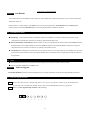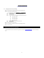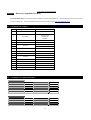
1
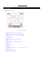
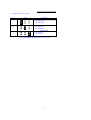
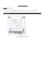
PCM-3900
USER MANUAL
PCM-3900 PC/104 IDE RAID Module
Copyright notice
This document is copyrighted, 2000, by Advantech Co., Ltd. All rights are reserved. The original manufacturer reserves the right to make improvements to the
products described in this manual at any
time without notice.
No part of this manual may be reproduced, copied, translated or transmitted in any form or by any means without the prior written permission of the original
manufacturer. Information provided in this
manual is intended to be accurate and reliable. However, the original manufacturer assumes no responsibility for its use, nor for any infringements upon the rights
of third parties which may result from its use.
Acknowledgements
AMD is a trademark of Advanced Micro Devices, Inc.
Award is a trademark of Award Software International, Inc.
Cyrix is a trademark of Cyrix Corporation.
IBM, PC/AT, PS/2 and VGA are trademarks of International Business Machines Corporation.
Intel and Pentium are trademarks of Intel Corporation.
Microsoft Windows ® is a registered trademark of Microsoft Corp.
RTL is a trademark of Realtek Semiconductor Co., Ltd.
C&T is a trademark of Chips and Technologies, Inc.
UMC is a trademark of United Microelectronics Corporation.
Winbond is a trademark of Winbond Electronics Corp.
For more information on this and other Advantech products, please visit our website at: http://www.advantech.com
For technical support and service, please visit our support website at: http://www.advantech.com/support
This manual is for the PCM-3291.
Part No. 2006390000
1st Edition Printed in Taiwan October 2001
3
PCM-3900 PC/104 IDE RAID Module
Chapter 1 Introduction.
PC/104 IDE RAID Module is an IDE to IDE Disk Array Controller. A “Real-Time-Backup” device designed for Enterprises, Schools, and Personal Using.
It provides a solution for low cost, high performance and redundant Disk Array function.
1.1
Functions and Features
✦ Data Mirroring: RAID Level 1 data mirror function. Backup data from one hard disk drive to another automatically, ensure your OS and important data
to be safe.
✦ Plug and Play: No need to install any device driver.
✦ OS Independence: Supports all PC operating systems.
✦ Auto Rebuild: Under system execution, if one hard disk drive is replaced, PC/104 IDE RAID Module will auto rebuild data to the new hard disk drive.
✦ Hot Swap: When one hard disk drive crashes, PC/104 IDE RAID Module allows you to remove it at once without power off. And by the mean while,
your system can work as usual.
✦ Firmware Upgradable: On-line WWW service, you can get newest firmware version via Internet.
✦ High Performance: System with PC/104 IDE RAID Module provides similar performance as with one single hard disk drive and provides high data
security for users.
✦ High Capacity: Hard disk drive capacity is no limitation.
✦ Easy Maintenance: Special DIY design. End-user can handle normal errors, and reduce MIS loading.
✦ System Indicators: Show system status by LEDs and the Buzzer.
✦ Host Compatibility: Supports IBM PCs, and compatible with most mainboards and chipsets.
✦ Hard Disk Compatibility: Supports all major brands’ IDE hard disk drives.
✦ Support Multi-boot System: Such as System Commander, IBM OS/2 Boot Manager, …….etc.
✦ RAID Manager: A software that operates with RAID system and allow user to Monitor and Remote Monitor the status of RAID systems.
1.2
System Requirements
✦ System: IBM PC Compatible Computer.
✦ CPU: Support Intel, AMD, Cyrix.
✦ Hard disk drive: Support most famous IDE hard disk drives, the capacity can be more than 30 Gbytes; Please make sure your device support LBA Mode
if it is smaller than 1 Gbytes.
4
PCM-3900 PC/104 IDE RAID Module
1.3
Specification
Host Interface
EIDE, IBM PC Compatible
HDD Interface
EIDE, Supports UDMA 33/66/100 HDD (Only UDMA33 for Maxtor HDD)
Card Interface
PC/104 Standard
RAID
!
RAID 1 (Mirror)
Transfer Rate
!
16.67MB/S (PIO mode 4) and 33.3MB/S (UDMA2)
Hot-Swap
!
Taking off HDD without shutdown the system
Auto-Rebuild
!
Automatically doing HDD's data reconstruction
!
1st HDD and 2nd HDD activity
!
Re-built
!
HDD Fail
!
FAT Copy or Sector Copy (FAT Copy Include FAT16, FAT32, NTFS)
!
3 * 90degree 2.54mm 40pin BOX header for 1 Host IDE and 2 Driver IDE
!
2 * 180 degree 2.00mm 44pin header for 2 Driver IDE
Power Connector
!
90 degree small 4 pin
Speaker
!
1* Alarm Speaker
!
EXT 1st HDD and 2nd HDD activity LED
!
EXT Re-built LED
!
EXT HDD Fail LED
!
EXT Speaker
!
Hot swap button
!
+5V
LED
Manual Rebuild
HDD Connector
EXT connector
Supply Voltages
5
PCM-3900 PC/104 IDE RAID Module
Operating Temperature
!
0℃ ~ 70℃
Cable
!
Host IDE × 1, Driver IDE × 2
Supports Operation Systems
!
!
!
!
!
!
!
Reliability
!
Windows NT Server and Workstation, DOS6.22, Windows 98/95/3.1x
NetWare 3.12/4.11/5.0,
SCO UNIX System V
OS/2
Linux (RedHat, Slack Ware, Debian, SuSe, OpenLinux, Turbo Linux)
Free BSD3.1
Solaris 2.x
MTBF > 250,000 hours
Chapter 2 How to Install
PC/104 IDE RAID Module is very easy to install. All you need is to install it the way just like what you may have done with a hard disk drive. Please read the
descriptions bellow in detail.
2.1
Before Installation (Important!)
When you use PC/104 IDE RAID Module, please keep the follwing descriptions in mind. Must means you have to follow the instruction; and Note means
please read it carefully:
✦ Using 2 New Hard Disks Note It is better for PC/104 IDE RAID Module to use two hard disk drives with the same brand and model.
✦ System Installation Note The user may install OS on one hard disk drive first, and then copy to another one by using “Auto Rebuild”
✦ Install a New Hard Disk Drive Must If you buy a new hard disk drive and want to use it with the original hard disk drive, the new hard disk’s capacity
must be equal or larger than the original one’s.
✦ Hard Disk Setup Must Please setup both of two hard disk drives in master mode, which is the default factory-setting mode.
6
PCM-3900 PC/104 IDE RAID Module
2.2
Device Description
PC/104 IDE RAID Module Layout and Parts:
Figure 2.1 PC/104 IDE RAID Module
1.
Host IDE Use an IDE ribbon cable to connect host onboard IDE slot
2.
HDD1 IDE Use one IDE ribbon cable to connect the hard disk drive HDD1
3.
HDD2 IDE Use one IDE ribbon cable to connect the hard disk drive HDD2
4.
2.5’’ true HDD form factor
5.
2.5’’ true HDD form factor
6.
1st LED status indicator, shows HDD1’s status( Failed or Normal )
7.
HDD1 access LED
8.
2nd LED status indicator, shows HDD2’s status( Failed or Normal )
9.
HDD2 access LED
10.
Rebuild LED
11.
External LED connector
12.
Jumper Setting
13.
Buzzer setting External Buzzer:Pin 1 +, pin 3 - ; Internal Buzzer:Pin 3 , 4 On
14.
RS-232 Connector
15.
IDE and Buzzer Switch ( See Table 2.2 )
16.
Buzzer Indicate warning or other message
7
PCM-3900 PC/104 IDE RAID Module
17.
Power In Connect to power supply
Item
1
2
3
Figure
Description
HDD1 IDE Switch
ON = HDD1 Insert
OFF =HDD1 Move
HDD2 IDE Switch
ON = HDD2 Insert
OFF =HDD2 Move
Buzzer Switch
ON = Power On
OFF =Power Off
Table2.2 PC/104 IDE RAID Module Jumper Setting description
8
PCM-3900 PC/104 IDE RAID Module
Chapter 3
How to Use
After the installation of PC/104 IDE RAID Module is completed, users may select the function conveniently just by altering Jumper setting.
3.1
Jumper Setting
Figure3.1 PC/104 IDE RAID Module Jupmer setting
9
PCM-3900 PC/104 IDE RAID Module
✦
Jumper Setting Description:
Item
1
2
3
Figure
8 7 6 5 4
8 7 6 5 4
8 7 6 5 4
3 2 1
3 2 1
3 2 1
Description
Master / Slave
ON = Master
OFF =Slave
Mirror / JBOD
ON = JBOD
OFF =Mirror
Upgrade Firmware
ON = Upgrade Mode
OFF =Normal Mode
Table3.1 PC/104 IDE RAID Module Jumper Setting description
✦ Using FDISK Note If you want to reinstall OS in two used hard disk drives synchronously, please first use FDISK to delete partitions of the two hard disk
drives respectively
10
PCM-3900 PC/104 IDE RAID Module
Chapter 4 Auto-Rebuild
You may install software into one hard disk drive first, and then use “Auto-Rebuild Function” described in this chapter, to copy the content of the first hard
disk drive into another one.
Reference Section 3.1 “Jumper Setting” to select “Mirror” mode. You may check system status by 1st and 2nd LED indicators and Buzzer (Please
reference Figure2.1 to check 1st and 2nd LED indicators). The meaning of LED indicators and Buzzer are as follows.
4.1
LED Indicator & Buzzer
✦ When Booting , 1 st and 2nd LEDs will blink once and Buzzer will alert once, and RAID Level 1 data mirror function already operates. This will
synchronize the two hard disk drives, and protect your operating system and important data on time.
✦ When one hard disk drive is broken-down The Buzzer will alert, you may know which hard disk drive is broken down by 1st and 2nd LED indicators.
If 1st LED indicator is red, it implies that HDD1 is broken down. If 2nd LED indicator is red, it implies that HDD2 is broken down. We suggest to
change the broken one to a normal one, to make sure your operating system and data to be safe.
✦ Auto-Rebuild When one hard disk drive is broken-down, user may replace it with a new one, our system will go into “Auto-Rebuild” mode. At this time,
the LED indicator of the hard disk drive that you just changed will blink. When “Auto-Rebuild” function is completed, the LED indicator will return to
the normal status.
4.2
Notes
✦ If one hard disk LED indicator doesn’t work, please check your LED firstly, you may reboot the system to check if it’s broken
✦ Make sure your HDD1 and HDD2 are set at Master mode。
Chapter 5 Firmware Upgrade
PC/104 IDE RAID Module provides easy firmware upgrade function, user can easily download new version firmware and upgrade utility from internet.
5.1
Firmware Upgrade Procedure
Note 1. Please make a DOS or Windows’ “Bootable Floppy Diskette” (The “Firmware Upgrade Disk”), and then copy the downloaded Firmware
Upgrade Utility (such as FLASH03.EXE) and NEW Firmware Code (such as FIRMWARE.BIN) to Firmware Upgrade Disk.
Note 2. Please set your F/W Upgrade Jumper or Switch => ON as following,
8
7
6
5
4
3
2
1
11
PCM-3900 PC/104 IDE RAID Module
Figure 5.1 Firmware Upgrade Jumper setting
#
Please upgrade your F/W as steps as following,
Step 1. Insert your Firmware Upgrade Disk and boot your system from Floppy Drive.
Step 2. Execute the DOS command as following,
A:\> (1) (2) (3) (For example: FLASH103.EXE 0 FIRMWARE.BIN)
(1) <= FLASH XXX.EXE (File name of Firmware Upgrade Utility)
(2) <= Parameter description : 0,1,2,3 present PC/104 IDE RAID Module position
0
: IDE Channel 1, Master;
1
: IDE Channel 1, Slave;
2
: IDE Channel 2, Master;
3
: IDE Channel 2, Slave
(3) <= XX-XX-XX.BIN (File name of New Firmware Code)
Step 3. Follow the steps show on the PC screen.
Step 4. After completion, set the Jumper or Switch back to original setting respectively
Step5.
5.2
Restart your system
Where To Get New Firmware & Upgrade Utility
You may download New Firmware Code and Firmware Upgrade Utility via Internet at http://www.Advantech.com.tw or contact ADVANTECH’s
agents.
12
PCM-3900 PC/104 IDE RAID Module
Chapter 6 Hardware Compatibility List (HCL)
PC/104 IDE RAID Module can be compatible with most of IBM PCs’ chipsets, and hard disk drives. All of the lists on below are part of our data which
are just for reference only. For more updated information, please check out from our web site: http://www.Advantech.com.tw.
6.1
Compatibility List of Chipsets
Item
Chipset
Mainboard
1
ALi M5229
ASUS P5A
ASUS P3B-F
ASUS P3B-1394
Iwill DBL100
GA-6BXC
2
Intel 440BX
3
Intel 810
ASUS MEW
4
Intel 820
ASUS P3C2000
5
Iwill WO2
Intel 815E
6
ASUS CUSL2
7
SIS 530
WinFast 5300MA
8
SIS 620
ASUS MES-VM
9
SIS 630
ASUS CUSI
10
Iwill VT133+
VIA694X
GA-6VX7-4x
11
6.2
12
VIA 694Z
ASUS CUV4X
13
AMD751
ASUS K7M
14
AMD761
ASUS A7M266
15
KT133
DFI AK74--EC
16
Serverworks ServerSet Ш LE
TYAN LES2510
Compatibility List of IDE Hard Disk Drives
(1)
(2)
(3)
(4)
(5)
Quantum
Model
LM20500AT
AS20000AT
LM15000AT
CX10200A
EL10A013
Size (GB)
20.5
20.0
15.0
10.2
10.0
(1)
(2)
(3)
Seagate
Model
ST340824A
ST330620A
ST330631A
Size (GB)
40.0
30.0
30.0
(6)
(7)
(8)
(9)
(4)
(5)
(6)
Model
KA9100A
CR8400A
CX6400A
CR6400A
Size (GB)
9.1
8.4
6.4
6.4
Model
ST328040A
ST320414A
ST315320A
Size (GB)
28.0
20.0
15.0
13
PCM-3900 PC/104 IDE RAID Module
(1)
(2)
Fujitsu
Model
MPG3307AT
MPD3091AH
Size (GB)
30.7
9.1
(3)
(4)
Model
MPD3064AT
MPD3043AT
Size (GB)
6.4
4.3
(1)
(2)
(3)
(4)
(5)
(6)
IBM
Model
DTLA-307075
DTLA-307045
DPTA-353750
DTLA-307030
DJNA-372200
DTLA-307020
Size (GB)
76.8
46.0
37.5
30.0
22.0
20.0
(7)
(8)
(9)
(10)
(11)
(12)
Model
DJNA-371800
DJNA-371350
DJNA-371010
DJNA-351010
DJNA-370910
DJNA-350640
Size (GB)
18.0
13.5
10.1
10.1
9.1
6.4
(1)
(2)
(3)
(4)
(5)
Maxtor
Model
98196H8
94098U8
94098U6
53073H6
32049H2
Size (GB)
81.0
40.0
40.0
30.0
20.0
(1)
Western Digital
Model
153BA
Size (GB)
15.0
(1)
Samsung
Model
SV2042N
Size (GB)
20.0
(6)
(7)
(8)
(9)
Model
52049H4
90841U2
90648D3
90432D2
Size (GB)
20.0
8.0
6.4
4.3
(2)
Model
WDAC28400
Size (GB)
8.4
14