1
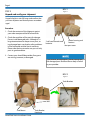
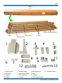
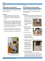
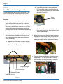
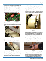
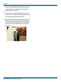
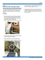
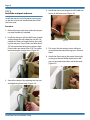
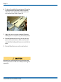
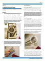
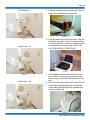
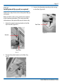
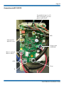
Vesta
Stair Lift
INSTALLATION MANUAL
AmeriGlide
Page 2
Hazard and Warnings
Do not connect/disconnect wiring while the power is on. Before
servicing, disconnect all power to the equipment.
SUDDEN MOVEMENT HAZARD
System may start unexpectedly upon application of power. Stay
clear of moving parts to avoid injury.
• Measuring Tape
• Box cutter, Pocket Knife, or Scissors
• Level
• Pencil, Marker, or Sharpie - Sharpie marks on
the track can be removed with hand sanitizer.
• Masking Tape for holding bolts in place
OPTIONAL: 1/4” Drill Bit to make pilot holes for the
track bracket lag bolts in hardwood floors.
NOTE: Concrete or steel floor installations require
special tools to insert the track bracket lag bolts.
AmeriGlide, Inc. is not responsible for any modifications of the
product made by the user. Do not allow unqualified personnel
to use the equipment. Failure to comply could result in death
or serious injury. Maintenance, inspection, and replacement of
parts must be performed only by authorized personnel familiar
with installation, adjustment, and maintenance. Do not remove
covers or touch circuit boards while power is on.
FIRE HAZARD
Do not use an improper voltage source. Before applying power,
verify that the rated voltage matches the voltage of the incoming power supply.
FOLLOW PROPER ESD PRECAUTIONS.
Before touching circuit boards, touch a grounding point to discharge any static electricity from your body.
Job Site Tools
The following list provides recommended tools and
materials to use during installation:
• Drill or Screwdriver with the following insert or
quick change bits:
Phillips #1, #2, #3 (small, medium, and large)
Allen 3mm, 4mm, and 5mm
Square #3
• Corded or Cordless Drill for inserting the track
bracket lag bolts and drilling optional pilot holes.
• Ratchet
• 13mm Socket
• 14mm Deep Socket
• 12” or longer Socket Extension
• 13mm Wrench or Adjustable Wrench
AmeriGlide Vesta Installation Guide
Page 3
List of installation steps
Follow the steps provided to ensure your safety during installation. Failure to follow instructions renders the Limited Warranty
null and void. In addition, any party installing the product who
deviates from the installation instructions agrees to indemnify,
save, and hold harmless the manufacturer from any and all loss,
liability, or damage that may occur as a result of the deviation.
Contents
Check the job site
3
Unpack and verify your shipment
4
Confirm the stair lift’s handing
6
Connect the track sections together
6
Track assembly
7
Install the bus lines
10
Install the motor housing on track
12
Adjust the motor housing post angle
15
Install the seat post and cover
16
Install the seat
17
Install the limit switch cams
19
Install the upper mechanical stop
21
Install the chargers
21
Check the remotes
22
Install the track end caps
23
Check the installation
24
Test the stair lift’s operation
24
Install optional flip-up rail (as required) 27
Electrical Diagrams and Troubleshooting
Flowchart28
Connections to MS125 PCB
29
Troubleshooting Flowchart
30
Diagnostic Codes
31
Remote Troubleshooting
33
Step 1
Check the job site
Read this manual in its entirety BEFORE beginning work. Confirm that you have all pages of the
manual. It’s better to find out now if there are any
issues that will prevent installation, and not when
you have a non-functioning stair lift taking up
room on your staircase.
Procedure
1. Clear the area so that you can bring in the stair
lift motor housing, seat, and track sections
from your staging area to the staircase.
2. Confirm that the track sections can be maneuvered into the staircase area. If you can’t get
the track through the door, now is the time to
find out!
3. Re-measure the staircase and confirm that
the measurements match what you sent with
your order. If the measurements don’t match,
please contact your AmeriGlide provider before
beginning work to see if the mismatch will
cause an issue or not. Your pre-cut track will be
10” longer than your stair case to allow for an
overhang at the top and bottom.
4. Ensure that the steps will support the maximum capacity of the Vesta stair lift, 300
pounds.
5. Ensure that there is a working, standard household outlet (110 VAC) located at the top or
bottom of the stairs to plug in the charger. It
should be non-switched to ensure that the
charger always has power.
6. Ensure that all electrical equipment and wiring
complies with applicable codes for your area.
7. Ensure that there are no fire and safety issues.
Contact your AmeriGlide provider if necessary.
8. Ensure that there is adequate lighting along
the staircase and at the landings.
AmeriGlide Vesta Installation Guide
Page 4
BOX 1
Step 2
Figure 1
Unpack and verify your shipment
Unpack the Vesta stair lift boxes and confirm that
you have all pieces and that all pieces are undamaged.
Procedure
1. Check the contents of the shipment against
your order receipt and the bill of materials.
2. Check the condition of the parts for damage.
Do not install damaged parts. Although it’s a
large inconvenience to request new parts, using damaged parts can lead to safety problems
in the future and void the Vesta’s warranty.
Please take the time to make sure you use only
parts in good condition.
2 call send controls and
batteries
Motor housing and
footrest
Seat post cover
3. Contact your AmeriGlide provider if any parts
are missing, incorrect, or damaged.
If you receive damaged parts, please photograph
the damaged parts and have them ready to email
to your provider.
BOX 2
Figure 2
Track Brackets
Seat
Seat Mount
AmeriGlide Vesta Installation Guide
Track Bracket
Hardware
Page 5
BOX 3
Figure 3
Side Bus Line Metal Ribbon
Rack
Track
Power Cables
Top Bus Line
1
6
1.
2.
3.
4.
2
8
7
Foot rest cover
Rail bracket
Seat post
Remotes
3
12
5.
6.
7.
8.
Remote holders
Electrical connectors
Limit switch cam
End caps
4
9 10
5
11
13
9. Mechanical stop
13. Rail bracket bolts
10. Key
11. Batteries
12. Rail bracket lag bolts
AmeriGlide Vesta Installation Guide
Page 6
Step 3
Confirm the stair lift’s handing
Step 4
Connect the track sections together
Confirm that you are installing the stair lift on the
proper side of the staircase and that this matches
what you ordered.
Connect the track sections together using the
splice bars provided. NOTE: If your Vesta installation requires only one section of track, you may
skip this section.
Procedure
1. To confirm if the stair lift is a left-hand or a
right-hand unit, begin by standing at the
bottom of the staircase looking up to the top
landing.
Procedure
1. Lay out the bottom section of track on the stairs
with the 1” rack piece that extends from the end
of the track facing towards the top landing.
2. If the stair lift will be installed on the left side of
the staircase, you are installing a left-hand unit.
If the stair lift will be installed on the right side,
you are installing a right-hand unit. (See Figure
4). Confirm that this matches what you ordered
from your AmeriGlide provider.
Note: The Vesta track can be used for either a
right or left handed install. You just have to be
sure that the gear teeth are facing downward.
NOTE: If you have a
right-hand unit, the
1” rack piece should
be facing the bottom
landing.
2. Remove the screw
from the 1” rack
piece using a square
bit. (Figure 6).
Figure 5
3. Flip the track over
4. After loosening all
the set screws in the
splice bars, insert the
splice bars into the track.
Figure 6
5. Tighten the 4 set screws in each splice bar that
are in contact with
the bottom section
of the track. You
should now have the
1” rack piece and 2
splice bars sticking
out from the track
section. (Figure 7).
Figure 4
Right-hand unit installed on right side of stairs
as viewed from bottom of stairway
AmeriGlide Vesta Installation Guide
6. Bring up the top secFigure 7
tion of track and lay it
so that it can be connected to the bottom section of track. To tell which way to orient the top
section of track, look for the 1” gap in the rack
where the rack piece from the bottom section of
Page 7
track will go into (Figure 8).
7. Carefully line up the two sections of track and
Step 5
Track assembly
Install the track mounting brackets on the track to
form a track assembly and then mount the track assembly to the stair treads.
Figure 8
insert the top section into the bottom section
of track. It will take a little bit of work to get the
track sections together – this is normal. If the top
section does not fit onto the splice bars, confirm
that the set screws are loose.
1. When installing the track assembly, the following
measurements must be maintained:
a. A clearance of ½” between the bottom of the
track and the floor at the bottom landing. If
this clearance is not maintained, you will not
be able to install the track end cap. (Figure
10)
8. Make sure there are no gaps in the rail and tighten the remaining set screws.
9. Flip the track over and insert and tighten the
rack screw as shown. The track sections are now
joined. (Figure 9).
Figure 10
b. A clearance of 4” between the bottom of
the rail and every step nose. If this clearance is not maintained, the footrest safety
sensor will be falsely triggered and the stair
lift will stop. (Figure 11).
Figure 9
Figure 11
c. A clearance of 3 ½” from the wall or obstacle
to the back of the track. If this clearance is not
maintained, the Vesta may catch on the wall,
causing damage to the Vesta unit.
OBSTACLES NOTE: The most common example of on obstacle is a hand rail. Measure
from the wall to the outside of the hand rail.
Add 3 ½” to this measurement. This result is
AmeriGlide Vesta Installation Guide
Page 8
the measurement from the wall that must be
maintained.
UNEVEN WALLS NOTE: Most walls are not
perfectly even. It’s important to just maintain
a minimum clearance of 3 ½” from the wall or
obstacle to the back of track. Larger clearances are okay.
d. Finally, a mounting bracket must be installed
on the first step from the bottom and top
landings and immediately before and after
any track splice. The remaining mounting
brackets should be placed at even intervals
between the required brackets.
2. BOTTOM BRACKET - Start by resting the track
on the nose of the steps with the bottom of the
track ½” off the floor. Temporarily put a track end
cap on to prevent the track from cutting into
the spacer. For the spacer, use the foam piece
from the motor housing box as shown. Place this
between the bottom of the track and the floor.
(Figure 12). This foam will also help to keep the
track from sliding while you work with it.
Figure 13
5. Install the lower bracket at an angle onto the
remaining two bolts and hand tighten the nuts,
starting with the bottom one. (Figure 14) If you
tighten the top bolt first, it may obstruct your
view.
Figure 14
6. Rotate the track back to its proper position and
place the track with the lower bracket against
the wall. Adjust the bracket positioning (you may
need to loosen the nuts just slightly) until you
get the 4” clearance between the bottom of the
Figure 12
3. Flip the track onto its side and install the 6 bolts
for the 3 brackets that will be installed in the
bottom section of track. Because of the track
splice bars you will not be able to slide the extra
bolts down from the top later - you must install
them now.
4. Use masking tape to hold the 4 bolts in place
that go to the middle bracket and the bracket
next to the splice. Place the tape immediately
behind the bolt. (Figure 13).
AmeriGlide Vesta Installation Guide
Figure 15
rail and the bottom step’s nose. (Figure 15).
7. Without moving the bracket or track, tighten the
top nut on the bracket. Once this is tight, move
the track assembly away from the wall so you
Page 9
can access the lower nut. Tighten the lower nut.
Swing the track assembly back to the wall and
confirm the 4” clearance. If you measure less than
4”, repeat the procedure until you get a 4” clearance.
8. Place the track assembly so there is a 3 ½” gap
between the wall or obstacle and the back of the
track. For most installations that are against a flat
wall with no obstacles, this simply means placing
the bracket against the wall.
Figure 16
9. Install one lag bolt into the bottom bracket and
tighten it to hold the bracket in place. Do not
place more than one lag bolt into the bracket
at this time. Otherwise you will not be able to
swing the track assembly out as required in later
steps. (Figure 17)
Figure 17
NOTE: If you have hardwood stair treads, be sure
to drill 1/4” pilot holes to prevent the wood from
splitting.
10.Before moving to the top bracket, slightly
loosen the top nut on the bottom bracket.
This will allow you to swing the end of the track
up and down as needed.
11.TOP BRACKET – Swing out the track slightly so
that you can access the back side of the top section of track. Slide in the 4 bolts for the brackets
that will be installed on the top section of track.
These bolts are for the middle bracket and the
bracket next to the splice.
12.Install the upper bracket onto the remaining two
bolts and hand tighten the nuts, starting with
the bottom nut.
13.Swing the track with the upper bracket against
the wall. Adjust the upper bracket positioning
(you may need to loosen the nuts just slightly)
until you get the 4” clearance between the
bottom of the rail and the nose of the step just
below the top landing.
14.Without moving the bracket or track, tighten the
top nut on the bracket. Once this is tight, swing
the track assembly away from the wall so you
can access the lower nut. Tighten the lower nut.
Swing the track assembly back to the wall and
confirm the 4” clearance. If you measure less than
4”, repeat the procedure until you get a 4” clearance.
15.Retighten the top nut on the bottom bracket.
16.Measure from the bottom of the rail to the nose
of every step on the staircase. Do not be surprised to find out that your steps are not even,
most steps are not. Any measurement 4” or larger is okay. If you find a measurement less than 4”,
you will need to increase the gap of the bracket
closest to that step (either the top or bottom
bracket) until you get at least a 4” measurement
at the problem step. If you run into problems,
please contact your AmeriGlide provider before
continuing.
17.You now have properly installed bottom and top
brackets on your track assembly. Swing the top
of the track assembly away from the wall and
install the remaining brackets as described in
the next step. Remember that you must have a
bracket in place immediately before and after
AmeriGlide Vesta Installation Guide
Page 10
the track splice. The other brackets should be
placed at even intervals between the required
brackets. If you feel you need extra brackets,
please contact your AmeriGlide provider before
continuing.
Step 6
Install the bus lines
Install the bus lines inside the track to provide
power for the stair lift.
18.As you add the brackets, just finger tighten the
nuts. Once all brackets are in place, swing the
track back against the wall. Move the brackets so
their bottoms are are flat against the stair tread.
Tighten the top nuts on all the brackets. (Figure
18).
Top bus line
Side bus line
Figure 18
19.Swing the track away from the wall and tighten
the bottom nut on each bracket.
20.Do not tighten the lag bolts on the bottom
bracket until you have removed the foam spacer
and bottom end cap.
21.Swing the track back against the wall. Confirm
that you are maintaining the proper 3 ½” gap
between the wall or obstacle and the back of
the track. Install the bracket lag bolts, starting
from the top of the stairs and working your way
down.
22.Make sure to tighten firmly the lag bolts using a
strong drill or by going back over the bolts and
tightening them with a wrench. On carpeted
stairs, the bases of the brackets will sink into the
carpet.
AmeriGlide Vesta Installation Guide
Figure 19
1. Determine if the charger for the Vesta stair lift
will be located at the bottom or the top of the
stairs. As noted earlier, the charger must be
plugged into a standard household 110 VAC
outlet that is non-switched.
2. Regardless of where the charger will be installed, the bus lines must be installed from
the top landing. Installing the bus line from the
bottom would be very awkward. (Diagram 1).
The bus line will be installed in the deepest of
the bus line holders.
Installation of bus line will be easier if a small
amount of WD-40 is applied to the plastic holder.
Page 11
6. SIDE BUS LINE: The side bus line is a bare metal
ribbon that is inserted down the plastic channel
already in side the track. It is the ground connection to the charger. Feed the side bus line
down the side plastic channel until only a 1 1/2”
metal strip of the metal ribbon is outside the
track, at either the top or bottom of the track.
Diagram 1
3. TOP LANDING CHARGER: The charger attaches to
the metal strips at the end of the bus lines with
quick connect female terminals. For a charger
located at the top landing, make sure to install
the bus line starting with the ends opposite the
metal strips. (Detailed pictures in Step 13).
Keeping the bus line in a roll and working it in
a little at a time is the best method. Do not allow the bus line to bend or kink. This will make it
much harder to install.
4. BOTTOM LANDING CHARGER: The charger attaches to the metal strips at the end of the bus
lines with quick connect female terminals. For
a charger located at the bottom landing, make
sure to install the bus line starting with the ends
that has the metal strips. (Detailed pictures in
Step 13).
5. TOP BUS LINE: The top bus line is a plastic strip
preloaded with a metal ribbon. It is the positive connection to the charger. Feed the bus
line down the channel located inside the track.
Continue to feed the top bus line until the plastic
covered section is completed inside the channel.
Only the metal strip for the charger attachment
should remain outside the channel (1 1/2”), on
either the top or bottom end of the track. (Figure
20).
Figure 20
AmeriGlide Vesta Installation Guide
Page 12
Step 7
Install the motor housing on track
Prepare the motor housing (also referred to as the
base or carriage) for installation and then install
the motor housing on to the track.
b. Is the drive sprocket in good condition?
If it has broken teeth or is not flush to the
drive shaft, please contact your AmeriGlide
provider. (Figure 22).
Procedure
1. Before beginning, check the condition of the
motor housing one more time. This is the best
time to address any problems with the motor
housing as you have easy access to it. It will also
make troubleshooting much easier should you
have problems with the stair lift after completing
installation.
2. Check the motor housing by visually inspecting
the limit switches, the charging plungers, and
the drive sprocket for broken parts and loose
wires. Specifically:
a. Are the arms of the limit switches straight?
If they are bent, please contact your AmeriGlide provider. (Figure 21).
Drive
Socket
Figure 22
c. Do all the roller wheels spin freely and
have snap rings? If not, please contact your
AmeriGlide provider.
3. Remove the top motor housing cover by removing the two Phillips head screws. Install the provided fuse into the fuse holder. The fuse does
not come installed as this help prevent battery
issues. (Figure 23A).
Normal Limit Switch
Figure 23A
4. Connect the negative battery wire to the terminal labeled “B-“ on the circuit board. The battery wire does not come installed as this helps
prevent battery issues. (Figure 23B).
Charging Plunger
Final Limit Switch
Charging Plunger
Figure 23B
Final Limit Switch
Figure 21
AmeriGlide Vesta Installation Guide
Negative Battery
Page 13
5. Once the fuse and battery are connected, you
should see a green LED on the front of the unit.
It will flash a few times and emit an audible
beep (16 times) before staying solid. It flashes
because the charger is not connected yet. You
do not need to connect the charger at this
time. It will be installed later. (Figure 24).
Figure 24
onto the track, be sure to guide the roller wheels
into their proper channels and that the drive
sprocket is in line with the rack in the track. You
will need to hold the motor housing at the same
angle as the track in order to make a smooth
transition. (Figure 27). NOTE: The motor housing
is heavy. This may be one step where you might
Green LED
6. Put the top motor housing cover back on and
screw in the two Phillips head screws. (Figure
25)
Figure 27
prefer assistance. Please do not lift a weight you
are uncomfortable lifting. NOTE: Be careful not
to damage the limit switches when sliding the
motor housing onto the track.
Figure 25
7. Use the temporary rope handle to assist in
lifting the motor housing. (Figure 26). You may
Figure 26
also wish to place your other hand underneath
the motor housing. Move the motor housing
into place by sliding it onto the track from the
top landing. As you slide the motor housing
8. The motor housing will only go a few inches
onto the rail. This is normal. To complete the
installation of the motor housing, you must
activate the temporary rocker switch that comes
Figure 28
attached to the motor housing. (Figure 28). This
will let you run the Vesta’s motor in the down
direction and move the motor housing down
the track. NOTE: All Vesta controls operate on
a 3-5 second delay as a safety feature. Please
AmeriGlide Vesta Installation Guide
Page 14
make sure to hold the control switch for at least 5
seconds before considering that there may be a
problem with the stair lift.
9. Run the Vesta using the temporary rocker switch
until there is a 12” gap from the end of the track at
the top landing to the motor housing.
10.Remove the temporary rope handle from the motor housing by removing the nuts from where it is
attached and taking the rope handle off. Replace
the nuts, but do not tighten them at this point.
(Figure 29).
Figure 29
AmeriGlide Vesta Installation Guide
Page 15
Step 8
Adjust the motor housing post angle
The motor housing post must be adjusted so that
it’s level. This ensures the footrest sensor works
properly and that passengers sit comfortably in
the seat.
rotate the plate as needed until the level shows
that the motor housing post is level.
3. Firmly tighten the three nuts. Confirm that the
motor housing post is still level. If the post’s position has changed, repeat the above steps until
the post is level.
Procedure
1. Place a level on the top of the motor housing
post. This will be your guide. In the unlikely
event the post is already level, you can skip to
step 3 of this section. (Figure 30).
If the seat will not level, remove the 3 nuts and
Figure 30
rotate the motor housing post to align with the
correct elongated hole pattern.
2. There are three nuts on the motor housing
plate. (Figure 31). Loosen these three nuts and
Figure 31
AmeriGlide Vesta Installation Guide
Page 16
Step 9
Install the seat post and cover
4. Attach the front cover diagnostic LED cable connector to the front cover. (Figure 34)
Install the seat post onto the motor housing post
so that the seat can be installed and then install
the front cover.
Procedure
1. Remove the nuts again from where the temporary rope handle was attached.
2. Install the seat post with the half-moon shaped
section facing the wall where the stair lift is attached. You have two height choices for installing the seat post. If most riders are taller than 5’
10”, we recommend setting the seat post high.
If most riders are shorter than 5’ 10”, we recommend setting the seat post low. (Figure 32).
Figure 34
5. The screws for the seat post cover will come
screwed into the motor housing post. Remove
these.
6. Attach the front cover to the motor housing by
screwing in the two Phillips head screws that
you just removed onto either side of the cover.
(Figure 35)
Figure 32
3. Secure the seat post by replacing the two nuts
and tightening them firmly. (Figure 33).
Figure 35
Figure 33
AmeriGlide Vesta Installation Guide
Page 17
Step 10
Install the seat
Install the seat onto the seat post and make any seat
adjustments necessary.
Procedure
1. Slide the seat onto the seat post. It should be a
fairly tight fit. (Figure 36).
OPTIONAL: 3-8
Do the following steps ONLY if you need to
adjust for a wider seat.
3. You can adjust the width of the seating area by
adjusting the arms in or out. If you do not need
to adjust the width of the seating area, please
skip the rest of this section.
4. Remove cover on the back side of the seat backrest. This will require you to remove four screws
and their washers. Set them aside. (Figure 38).
Figure 36
2. Remove the temporary rocker switch. Plug the
seat cable into where the temporary rocker
switch was connected on the motor housing.
(Figure 37).
Figure 37
Figure 38
5. With the cover off, locate the two hex bolts and
nuts on the back side of the seat backrest. Remove them and set them aside. (Figure 39).
Figure 39
AmeriGlide Vesta Installation Guide
Page 18
6. To adjust the width of the seating area, flip up the
seat and locate the hex bolts and nuts on each
side of the seat support. Remove the bolts and
nuts and set them aside. (Figure 40).
Figure 40
7. Adjust the arms in or out as required. The tubes
holding the arms may be snug. Please be patient.
8. Reinstall the hex bolts and nuts on the seat support and the seat backrest. Make sure the seat is
vertical before locking the lower nuts and bolts in
place.
9. Reinstall the plastic over on the seat backrest.
Be careful not to damage the wiring from the motor
housing to the base of the seat while performing this
operation.
AmeriGlide Vesta Installation Guide
Page 19
Step 11
Install the limit switch cams
Install the limit switch cams into the top and bottom
of the track to prevent the stair lift from overrunning
the track.
Procedure
1. You will install the upper and lower limit switch
cams into the top bus line that you installed
previously. The cams fit by sliding into the plastic
section of the top bus line over top of the metal
ribbon running throughout the bus line. (Figure 41) The measurements required depend on
whether you are install a left-hand or right-hand
unit. Make sure you follow the proper set of
instructions.
out. (Figure 42).
3. LEFT-HAND UNIT. The upper limit switch cam
should be 2 ½” from the end of the top of the
track to the screw end of the cam. The lower
limit switch cam should be 9” from the end of
the bottom of the track to the screw end of the
cam. Lock the cams in place by screwing in the
Phillips head screw located on the cam. Confirm
that your measurements are correct. (Diagram
2).
4. RIGHT-HAND UNIT. The upper limit switch
cam should be 9” from the end of the top of the
track to the screw end of the cam. The lower
limit switch cam should be 2 ½” from the end of
the bottom of the track to the screw end of the
cam. Lock the cams in place by screwing in the
Phillips head screw located on the cam. Confirm
that your measurements are correct. (Diagram
3).
5. The side limit switches need to be installed into
the side bus line. They are installed flush with
the end of the side bus line (Figure 43).
Figure 41
2. The easiest way to accurately place the cams is
by using a tape measure and then marking the
proper distance with a pencil or other marker.
This frees your hands to move the cams in and
Figure 43
6. Run the lift and confirm that the stair lift stops at
the proper place. If the stair lift appears to stop
to soon or late, check the positioning of your
cams. If the stair lift fails to stop, please contact
your AmeriGlide provider before continuing.
Figure 42
AmeriGlide Vesta Installation Guide
Page 20
Left-Hand Unit
Diagram 2
Right-Hand Unit
Diagram 3
AmeriGlide Vesta Installation Guide
Page 21
Step 12
Install the upper mechanical stop
Step 13
Install the chargers
Install the upper mechanical stop. This prevents the
motor housing from overrunning the track should
the limit switches fail to operate.
Install the charger at the upper or lower landing as
you previously determined.
Procedure
Procedure
1. The lower mechanical stop is factory installed.
(Figure 44) The upper mechanical stop cannot
be installed until the motor housing is put onto
the track.
1. Do not plug the charger into the wall outlet until
the charger is connected to the bus line.
2. To connect the charger to stair lift, you will need
to connect a ground wire and a power wire. To
attach the black wire, remove the screw shown
below, insert through hole at the end of the
black wire and screw back in (Figure 46).
Figure 44
2. To install the upper mechanical stop, place it
behind the front of the track with the hole in the
stop aligned with the hole in the track. Screw in
the bolt and secure the bolt with the provided
nut. (Figure 45)
Figure 46
3. The upper bus line connects to the white wire
and the black wire to the side bus line (Figure
46). Do not allow copper stripe to contact the
rail or each other.
4. Confirm all connections are correct.
Figure 45
3. During normal operation, the lift should never
touch either mechanical stop. The limit switch
cams stop the lift during normal operation.
5. Route the wiring behind the track using the
lower bolt track (where the bracket bolts go),
then place the lower track end cap on.
6. Plug the charger into the wall outlet. You should
see a green LED light up on the charger if everything is okay. (Figure 47).
7. Mount the charger on the wall at the top or
bottom of the stairway as appropriate for your
AmeriGlide Vesta Installation Guide
Page 22
Step 14
Check the remotes
Check that the included call-send remotes work
and install their holders on the wall.
Figure 47
installation. Using the bracket and two screws
provide, secure the charger to the wall (drill
holes as required) (Figure 48).
1. Call-send remotes come pre-programmed
from your AmeriGlide provider. Customers with
double stair lift installs will have the call-send
remotes programmed on different frequencies
so that each set of controls works with only one
unit.
On left handed units, the green button will move
the stair lift up. The red button will move the stair
lift down. For right handed units, this is reversed.
2. Remove the battery covers on the call-send
remotes and install the provided 9V batteries
in the remotes. (Figure 49). Replace the battery
Figure 48
Figure 49
covers. The red LED on the remove will light up
when you press either button if the batteries
have been installed properly. (Figure 50).
Figure 50
AmeriGlide Vesta Installation Guide
Page 23
3. Vesta call-send remotes are Infrared (IR) remotes.
This means they must be pointed at the sensors
located on either side of the motor housing.
Point each call-send remote at the motor housing and confirm that it works. As noted before,
all Vesta controls operate on a 3-5 second delay
as a safety feature. Please make sure to press
and hold the button for at least 5 seconds before
considering that there may be a problem with
the stair lift.
4. Call-send remote holders should be mount at
the top and bottom landings. Simply orient the
holder properly and screw the holder into place.
(Figure 51). Place a call-send remote into each
holder. (Figure 52.)
Step 15
Install the track end caps
Install the track end caps.
Procedure
1. The track end caps go on to the bottom and top
ends of the track. (Figure 53).
2. To install the caps, simply slide them over the
end of the track, and screw in the provided Phillips head screws, one per end cap. Confirm that
the electrical connections were not jostled when
you placed the cap on.
Secure bottom rail cap with screw
Figure 51
Figure 53
Figure 52
AmeriGlide Vesta Installation Guide
Page 24
Step 16
Check the installation
Step 17
Test the stair lift’s operation
Do a visual check of the installation before beginning
testing.
Test the operation of your Vesta stair lift.
Procedure
1. Verify that all electrical connections have been
made properly. This includes the charger connections and the wire running from the switch
on the seat to the motor housing.
2. Verify that all nuts and screws are firmly tightened.
3. Verify that all track mounting brackets are stable.
Time spent testing your Vesta stair lift now can
prevent long term operational and maintenance
issues. Please take a few extra minutes to perform
all the checks listed below. Issues you overlook
now can cause extra wear and tear that means
extra downtime in the future. If any check fails, do
not use your stair lift until you have resolved the
issue with your AmeriGlide provider.
Procedure
1. Does the up/down rocker switch on the seat’s
arm function properly? The switch is constant
pressure and must be pressed and held to operate. Remember that there is a 3-5 second delay
between pressing a switch and a response from
the Vesta stair lift. This is a safety precaution and
is normal.
2. Do both up and down buttons on each call-send
control work?
3. Do the seat, armrests, and footrest fold up properly? (Figure 54).
Figure 54
4. Does the seat swivel handle work properly? Does
it lock the seat in the 0° (Figure 55), 45° (Figure
56), and 90° (Figure 57) positions?
AmeriGlide Vesta Installation Guide
Page 25
Seat Position - 0o
5. Does the seat belt slide in and out easily? Does it
buckle and unbuckle easily (Figure 58)?
Figure 58
Figure 55
Seat Position - 45o
6. Does the footrest sensor work properly? The stair
lift should stop when it comes in contact with an
obstacle on the stairs. Please use a piece of wood
or other object for testing. (Figure 59) DO NOT
USE YOUR ARM OR LEG FOR TESTING.
Figure 59
Figure 56
Seat Position - 90o
7. Do the upper and lower limit switches work? If
the stair lift is traveling to the mechanical stop,
please contact your AmeriGlide provider for support.
8. Does the swivel seat safety switch work? The stair
lift should not operate if the seat is not locked
in the ride position (0 degrees or parallel to the
staircase). (Figure 60)
Figure 57
Figure 60
AmeriGlide Vesta Installation Guide
Page 26
9. Inspect the rack and gear and ensure that the motor housing travels smoothly along the rail. Only
apply white lithium grease if there is squeaking
during operation.
10.Does the LED on the front cover of the motor
housing light up green? It should be a steady
green light. If it’s flashing, there is an issue with
the charger. Please check that the charger is
plugged in and on. You will see a green light on
the charger itself.
11.If you hear a beeping sound that starts after using
the lift and lasts for 16 beeps, there is an issue
with the charger. Please refer to Step 13.
12.Finally, ride the stair lift yourself. Do you feel the
stair lift is working properly? If not, please contact
your AmeriGlide provider for support.
AmeriGlide Vesta Installation Guide
Page 27
Step 18
Install optional flip-up rail (as required)
3. Screw in the foot plate according to the tracing
on the floor (Figure 63).
Follow these steps if the unit has the optional flip-up
rail section.
Refer to STEP 5 earlier in this guide for the standard
track installation procedure. This section provides
information on the optional flip-up rail section only.
1. Attach the special mounting bracket to the flipup rail section (Figure 61).
Face Plate
Figure 63
Bracket
Foot Plate
Figure 61
2. Trace the foot plate location on the floor (Figure 62).
Figure 62
AmeriGlide Vesta Installation Guide
Page 28
Electrical Diagrams and Troubleshooting Flowchart
AmeriGlide Vesta Installation Guide
Page 29
Connections to MS125 PCB
Terminal block (pins 1 to 17)
Refer to diagram on previous
page for signal details
LEDs
CN6 and CN7
Infrared receiver
Charger input
(CONN18)
Motor 1 (red) and
Motor 2 (black)
GND
Vbatt
B-
AmeriGlide Vesta Installation Guide
AmeriGlide Vesta Installation Guide
Replace PCB.
0 VDC
0 VDC
Check if terminal pins
are shorted together.
If not, replace PCB.
Short circuit in wires connected
in terminals 1 to 17
or infrared sensors.
Test motor directly on battery (VBatt,
GND). Replace motor if necessary.
0 VDC
Check charger operation.
Check for charger voltage
(33 VDC) between GND and
the PCB charger input terminal
when the lift is parked
at either landing.
Green LED flashing
33 VDC
PCB is in sleep mode.
Try to run the unit from
the control switch.
Amber LED on
Lift will not run if standby
voltage is below 21.5 VDC
or the voltage under use
drops below16.5 VDC.
Runs at slow speed
Check charging circuit.
Pull one end of the main fuse out of the fuse holder
and make an amperage test with a multimeter.
The amperage reading will vary depending on the
state of charge of the batteries (max 1 Amp).
Another method is to check if the battery voltage
goes up over time. If no amperage, replace PCB.
33 VDC
Check for 120 VAC at charger input.
Check for 33 VDC at charger output on charging station.
Check for 33 VDC along charger plunger and wiring to PCB terminal.
Correct problem and/or replace battery charger as necessary.
Loss of continuity
between terminals 1-3.
Verify final limit switch
and swivel seat switch.
Red LED on or flashing
3.3 - 3.4 VDC
Check voltage between
terminal 1 and GND.
Disconnect terminals 1 to 17
and infrared sensors.
Voltage above 20 VDC
If voltage okay everywhere,
check output DC voltage between
Motor 1 and Motor 2 when
pushing up or down switch.
Caution: A short circuit between
these 2 terminals will damage PCB.
Check main fuse.
Replace if necessary.
Check DC voltage between GND
and terminals 3, 4, 6, 8, 11, 16.
If the lift needs to travel right,
there must be voltage
between B- and 7, 9, 10, 17.
If the lift needs to travel left,
there must be voltage
between B- and 5, 12, 13, 15.
Repair any open circuits.
If still 0 VDC
0 VDC
VDC
Check DC voltage
between #1 and GND.
No LED on
Reset the PCB.
Disconnect the battery charger. (Disconnect the battery wire
going to the B+ terminal. Reconnect the B+ terminal.)
Measure battery voltage between VBatt and GND.
Register LED status on circuit board.
Lift is not moving
Troubleshooting Procedure
Vesta (MS 125 Board)
Page 30
Troubleshooting Flowchart
Page 31
Diagnostic Codes
For codes displayed on the diagnostic display, refer to the following table to help diagnose and correct any
faults.
If the recommended corrective action provided in the table does not
solve the problem, contact your authorized dealer for assistance.
Code
Status/Fault
No display.
-
On when the stairlift is okay; ready to use.
Flashing when the stairlift is running.
Recommended Corrective Action
Press the UP/DOWN rocker switch and see
if the display comes on. Check that the key
switch and ON/OFF switch are turned on.
No action required.
0
Final limit switch is activated or swivel
seat switch is activated.
Check that the key switch is ON and the seat is
fully swivelled to the riding position.
1
Batteries require charging.
Check that the charger is plugged in and
charging.
2
Batteries not charging.
Check that the charger is plugged in and
charging.
3
Upper limit safety switch is activated.
You have reached the upper limit. Run the unit
in the down direction.
4
Safety edge switch (bumper) in up direction is activated.
Remove any obstacle that may have activated
the switch.
5
Underpan switch is activated.
Remove any obstacle from underneath the
footrest.
6
Safety edge switch (bumper) in down
direction is activated.
Lower limit safety switch is activated
Remove any obstacle that may have activated
the switch.
You have reached the lower limit. Run the unit
in the up direction.
AmeriGlide Vesta Installation Guide
Page 32
7
Batteries approaching critical level and
need charging.
Check that the charger is plugged in and
charging.
9
Rocker switch is activated in UP/DOWN
direction.
No action required.
A
Hinge is open.
Contact your authorized dealer.
B
A switch is active at power on (toggle up,
toggle down, IR up, IR down, or learn.
Contact your authorized dealer.
C
IR address (DIP switch) does not match.
Contact your authorized dealer.
D
Main power relay is welded.
Contact your authorized dealer.
E
Main power relay did not close.
Contact your authorized dealer.
G
Brake not connected.
Contact your authorized dealer.
H
Main power relay has closed early.
Contact your authorized dealer.
L
Current limit exceeded.
Contact your authorized dealer.
N
Stairlift is running at half speed.
Contact your authorized dealer.
O
Main control board has a memory problem.
Contact your authorized dealer.
P
Powered swivel did not respond.
Contact your authorized dealer.
R
No charging current.
Check that the charger is plugged in and
charging.
AmeriGlide Vesta Installation Guide
Page 33
Remote Troubleshooting
Remote not functioning no lights
1. Check and replace the 9v battery.
Remote not functioning w/lights
1. Confirm the lift is functioning by operating the
onboard control.
2. Remove the stair lift’s cover panel to access the
main circuit board.
3. Press and hold the red button located next to
the 17 pin plug on the circuit board (Figure 58).
4. Press and hold the up or down button on the
remote control.
5. Release the red button on the circuit board.
The unit at this time should beep and start moving.
If the unit is at one of the end stops, you may find the
lift does not beep when you release the red button
on the circuit board, if that is the case then press the
other button on the remote.
If one or both remotes do not work after this procedure, then unscrew the back cover of the remote (4
screws - 2 are located beneath the battery cover) and
reverse the dip switch settings (Figure 59), and repeat
the steps described above.
Figure 58
Figure 59
AmeriGlide Vesta Installation Guide
Page 34
AmeriGlide Vesta
INSTALLATION GUIDE
Part No. 000811 Copyright © 2011
AmeriGlide, Inc
www.ameriglide.com
Support
3901 Commerce Park Drive
Raleigh, NC 27610
Toll Free: 855-595-0278
AmeriGlide
AmeriGlide Vesta Installation Guide