1
User's Guide
REFERENCE
86 A1 97EV 01
NOVASCALE
NovaScale T840
NOVASCALE
NovaScale T840
User's Guide
Hardware
September 2008
BULL CEDOC
357 AVENUE PATTON
B.P.20845
49008 ANGERS CEDEX 01
FRANCE
REFERENCE
86 A1 97EV 01
Proprietary Notice and Liability Disclaimer
The information disclosed in this document, including all designs and related materials, is the valuable property of
NEC Computers and/or its licensors. NEC Computers and/or its licensors, as appropriate, reserve all patent,
copyright and other proprietary rights to this document, including all design, manufacturing, reproduction, use, and
sales rights thereto, except to the extent said rights are expressly granted to others.
To allow for design and specification improvements, the information in this document is subject to change at any
time, without notice. Reproduction of this document or portions thereof without prior written approval of NEC
Computers is prohibited.
The Bull product(s) discussed in this document are warranted in accordance with the terms of the Warranty Statement
accompanying each product. However, actual performance of each product is dependent upon factors such as
system configuration, customer data, and operator control. Since implementation by customers of each product may
vary, the suitability of specific product configurations and applications must be determined by the customer and is
not warranted by Bull.
Trademarks
NEC ESMPRO, NEC DianaScope, NEC MWA, and ExpressBuilder are trademarks or registered trademarks of NEC
Corporation.
NovaScale is a registered trademark of Bull SAS.
Adobe, and Adobe Acrobat are registered trademarks of Adobe Systems, Incorporated.
Microsoft, Microsoft Windows, Windows NT, Windows 95, Windows 98, Windows2000 and Windows Server
2003 are all registered trademarks of Microsoft Corporation.
MS-DOS is a registered trademark of Microsoft Corporation.
Intel and Xeon are registered trademarks of Intel Corporation.
All other product, brand, or trade names used in this publication are the trademarks or registered trademarks of their
respective trademark owners.
Copyright © NEC Computers SAS 2006
Suggestions and criticisms concerning the form, content, and presentation of this manual
are invited. A form is provided at the end of this manual for this purpose.
The information in this document is subject to change without notice. Bull will not be liable for errors contained herein, or for
incidental or consequential damages in connection with the use of this material.
User Guide
www.bull.com
Table of Contents
Table of Contents . . . . . . . . . . . . . . . . . . . . . . . . . . . . . . . . . . . . . . . . . . . . . 5
Text Conventions . . . . . . . . . . . . . . . . . . . . . . . . . . . . . . . . . . . . . . . . . . . . . . . . . . . . . . . . . . . . . 12
Safety Notices . . . . . . . . . . . . . . . . . . . . . . . . . . . . . . . . . . . . . . . . . . . . . . . 13
Regulatory Information . . . . . . . . . . . . . . . . . . . . . . . . . . . . . . . . . . . . . . . . . . . . . . . . . . . . . . . . 13
European Notice ............................................................................................................
USA and Canada Notice ................................................................................................
Modifications to the Product..........................................................................................
Connections and Remote Earths ....................................................................................
Power Supply and Cables ..............................................................................................
Batteries .........................................................................................................................
Chassis Cover Removal and Replacement ....................................................................
Laser Compliance Statement .........................................................................................
Warning - Hazardous Voltage! ......................................................................................
Warning -Avoid Electrostatic Discharge!......................................................................
Product Disposal ............................................................................................................
13
14
14
14
15
15
15
16
16
16
16
System Features . . . . . . . . . . . . . . . . . . . . . . . . . . . . . . . . . . . . . . . . . . . . . 17
Related Documents . . . . . . . . . . . . . . . . . . . . . . . . . . . . . . . . . . . . . . . . . . . . . . . . . . . . . . . . . . . 18
Rear View ...................................................................................................................... 19
Status Indicators. . . . . . . . . . . . . . . . . . . . . . . . . . . . . . . . . . . . . . . . . . . . . . . . . . . . . . . . . . . . . . 21
Front Panel..................................................................................................................... 21
Back Panel ..................................................................................................................... 22
Internal View ................................................................................................................. 23
Motherboard . . . . . . . . . . . . . . . . . . . . . . . . . . . . . . . . . . . . . . . . . . . . . . . . . . . . . . . . . . . . . . . . . 24
Motherboard Layout ......................................................................................................
CMOS and Password Clear Jumpers .............................................................................
Reconnect the AC power and power up the system. .....................................................
BIOS Select Jumper.......................................................................................................
Back Panel Connectors ..................................................................................................
Memory Configuration ..................................................................................................
24
25
27
27
28
28
Standard Features . . . . . . . . . . . . . . . . . . . . . . . . . . . . . . . . . . . . . . . . . . . . . . . . . . . . . . . . . . . . 32
Processor........................................................................................................................
Memory..........................................................................................................................
Expansion Slots..............................................................................................................
Video..............................................................................................................................
Network Controller ........................................................................................................
ACPI ..............................................................................................................................
Keyboard and Mouse .....................................................................................................
Peripheral Bays ..............................................................................................................
RAID Support ................................................................................................................
Peripheral Bays ..............................................................................................................
32
32
32
32
33
34
34
34
34
36
Optional Features . . . . . . . . . . . . . . . . . . . . . . . . . . . . . . . . . . . . . . . . . . . . . . . . . . . . . . . . . . . . . 37
DVD-ROM Drive .......................................................................................................... 38
DVD Writer Combination Drive ................................................................................... 39
5
User Guide
www.bull.com
Sony AIT-1 Turbo Tape Drive (IDE) ............................................................................
Sony AIT-2 Turbo Backup Unit (IDE)..........................................................................
LTO 2 Tape Drive (SCSI) .............................................................................................
DAT72 Tape Drive (USB).............................................................................................
Sony AIT-3 Ex Backup Unit (SCSI) .............................................................................
Syskonnect single port PCI-E x1 LAN Board ..............................................................
Intel Pro/1000 PT Dual Port LAN Board ......................................................................
Intel Pro/1000 MT Dual Port LAN Board .....................................................................
S-ATA Hard Disk Drive ................................................................................................
SCSI Hard Disk Drive ...................................................................................................
SAS Hard Disk Drive ....................................................................................................
Adaptec 29160ALP SCSI Controller.............................................................................
Adaptec 29320ALP SCSI Controller.............................................................................
LSI SecuRAID 114 SCSI Controller .............................................................................
Promise Ultra133 TX2 (IDE) ........................................................................................
Promise SuperTrack EX8350 RAID Controller (SATA) ..............................................
LSI 8704 SAS RAID Controller....................................................................................
LSI 8708EM2 SAS/SATA RAID Controller ................................................................
Emulex 1150 Fiber Channel Card .................................................................................
IEEE 1394 Controller Card............................................................................................
RAID 5 Activation Key .................................................................................................
41
42
43
44
45
46
47
49
50
51
52
53
54
55
57
58
60
62
63
64
65
Setting Up Your System . . . . . . . . . . . . . . . . . . . . . . . . . . . . . . . . . . . . . . . 66
Setting Up Your Server (Rack). . . . . . . . . . . . . . . . . . . . . . . . . . . . . . . . . . . . . . . . . . . . . . . . . . . 67
Setup Flow. .................................................................................................................... 67
Selecting Server Site...................................................................................................... 68
Setting Up Your System (Tower) . . . . . . . . . . . . . . . . . . . . . . . . . . . . . . . . . . . . . . . . . . . . . . . . . 70
Setup Flow. .................................................................................................................... 70
Selecting System Site..................................................................................................... 71
Unpacking the System . . . . . . . . . . . . . . . . . . . . . . . . . . . . . . . . . . . . . . . . . . . . . . . . . . . . . . . . . 72
System Chassis Features . . . . . . . . . . . . . . . . . . . . . . . . . . . . . . . . . . . . . . . . . . . . . . . . . . . . . . 73
Front View with Front Bezel ......................................................................................... 73
Front View without Front Bezel .................................................................................... 74
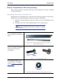
Rack Installation Kit Assembly . . . . . . . . . . . . . . . . . . . . . . . . . . . . . . . . . . . . . . . . . . . . . . . . . . 75
Unpacking the Rack Installation Kit..............................................................................
Before You Begin ..........................................................................................................
Static Precautions...........................................................................................................
Assembly .......................................................................................................................
Assembling the Front and Rear Parts of Support Rails .................................................
Installing the Support Rails............................................................................................
Installing the Filler on the Server ..................................................................................
Installing the Server in the Rack Cabinet ......................................................................
75
77
78
78
79
80
81
82
Making Connections. . . . . . . . . . . . . . . . . . . . . . . . . . . . . . . . . . . . . . . . . . . . . . . . . . . . . . . . . . . 83
Power Supply . . . . . . . . . . . . . . . . . . . . . . . . . . . . . . . . . . . . . . . . . . . . . . . . . . . . . . . . . . . . . . . . 84
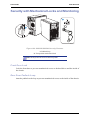
Connecting the Power Cord(s)....................................................................................... 84
Hot-Swappable Power Supply Features ........................................................................ 85
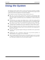
Using the System. . . . . . . . . . . . . . . . . . . . . . . . . . . . . . . . . . . . . . . . . . . . . 87
Powering On your System . . . . . . . . . . . . . . . . . . . . . . . . . . . . . . . . . . . . . . . . . . . . . . . . . . . . . .
Powering Off your System . . . . . . . . . . . . . . . . . . . . . . . . . . . . . . . . . . . . . . . . . . . . . . . . . . . . . .
Forcing a Power Shutdown . . . . . . . . . . . . . . . . . . . . . . . . . . . . . . . . . . . . . . . . . . . . . . . . . . . . .
Resetting the System . . . . . . . . . . . . . . . . . . . . . . . . . . . . . . . . . . . . . . . . . . . . . . . . . . . . . . . . . .
6
88
90
91
92
User Guide
www.bull.com
Configuring Your System . . . . . . . . . . . . . . . . . . . . . . . . . . . . . . . . . . . . . . 93
Configuring RAID . . . . . . . . . . . . . . . . . . . . . . . . . . . . . . . . . . . . . . . . . . . . . . . . . . . . . . . . . . . . . 94
RAID Configuration Utility........................................................................................... 94
RAID Levels .................................................................................................................. 95
RAID Configuration Using Promise Array Management . . . . . . . . . . . . . . . . . . . . . . . . . . . . . 98
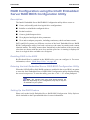
RAID Configuration using the Intel® Embedded Server RAID BIOS Configuration Utility . . 99
Description.....................................................................................................................
Enabling RAID in the BIOS ..........................................................................................
Entering the Intel Embedded Server RAID BIOS Configuration Utility ......................
Setting Up the RAID Feature.........................................................................................
99
99
99
99
RAID Configuration using SuperBuildTM . . . . . . . . . . . . . . . . . . . . . . . . . . . . . . . . . . . . . . . . 100
RAID Configuration using the SCSISelect Utility. . . . . . . . . . . . . . . . . . . . . . . . . . . . . . . . . . . 101
Installing the Hard Disk Drives ................................................................................... 101
Enabling the RAID Feature using the SCSISelect Utility ........................................... 101
Creating Arrays............................................................................................................ 106
RAID Configuration using the MegaRAID Configuration Utility . . . . . . . . . . . . . . . . . . . . . . . 116
RAID Configuration using the LSI Logic Software RAID Configuration Utility . . . . . . . . . . 117
Running the Setup Utility ............................................................................................
Operating Procedures for the Setup Utility..................................................................
Manual Rebuild............................................................................................................
Setting a Hot Spare ......................................................................................................
Check Consistency.......................................................................................................
Others Operations ........................................................................................................
117
120
124
125
127
128
RAID Configuration using the MegaRAID Configuration Utility . . . . . . . . . . . . . . . . . . . . . . . 129
Configuring the BMC . . . . . . . . . . . . . . . . . . . . . . . . . . . . . . . . . . . . . . . . . . . . . . . . . . . . . . . . . 130
Overview......................................................................................................................
Installation ...................................................................................................................
SELVIEW....................................................................................................................
SYSCFG ......................................................................................................................
130
130
130
131
Upgrading Your System . . . . . . . . . . . . . . . . . . . . . . . . . . . . . . . . . . . . . . 138
General Safety Information . . . . . . . . . . . . . . . . . . . . . . . . . . . . . . . . . . . . . . . . . . . . . . . . . . . .
Static Precautions. . . . . . . . . . . . . . . . . . . . . . . . . . . . . . . . . . . . . . . . . . . . . . . . . . . . . . . . . . . .
Equipment Log . . . . . . . . . . . . . . . . . . . . . . . . . . . . . . . . . . . . . . . . . . . . . . . . . . . . . . . . . . . . . .
Tools Recommended to Upgrade Your System. . . . . . . . . . . . . . . . . . . . . . . . . . . . . . . . . . . .
Preparing Your System for Upgrade. . . . . . . . . . . . . . . . . . . . . . . . . . . . . . . . . . . . . . . . . . . . .
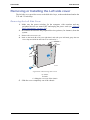
Removing or Installing the Left side cover . . . . . . . . . . . . . . . . . . . . . . . . . . . . . . . . . . . . . . .
138
139
139
139
139
140
Removing the Left Side Cover .................................................................................... 140
Replacing the Left Side Cover..................................................................................... 141
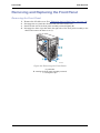
Removing and Replacing the Front Panel . . . . . . . . . . . . . . . . . . . . . . . . . . . . . . . . . . . . . . . . 142
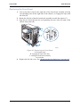
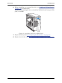
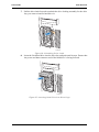
Removing the Front Panel ........................................................................................... 142
Replacing the Front Panel............................................................................................ 143
Installing or Removing a 5.25-inch Device . . . . . . . . . . . . . . . . . . . . . . . . . . . . . . . . . . . . . . . . 144
Adding a 5.25-inch Device .......................................................................................... 144
Removing a 5.25-inch Drive........................................................................................ 146
Fix Hard Disk Drives . . . . . . . . . . . . . . . . . . . . . . . . . . . . . . . . . . . . . . . . . . . . . . . . . . . . . . . . . . 148
Installing a Fixed Hard Disk Drive.............................................................................. 148
Removing a Fixed Hard Drive..................................................................................... 156
Hot-Swap Hard Disk Drives . . . . . . . . . . . . . . . . . . . . . . . . . . . . . . . . . . . . . . . . . . . . . . . . . . . . 159
Removing and Replacing a Hot-Swap Hard Disk Drive ............................................. 159
Cabling the Hot-Swap Hard Disk Drive Cages ........................................................... 161
Upgrading Microprocessor . . . . . . . . . . . . . . . . . . . . . . . . . . . . . . . . . . . . . . . . . . . . . . . . . . . . 166
Upgrading Random Access Memory (RAM). . . . . . . . . . . . . . . . . . . . . . . . . . . . . . . . . . . . . . . 171
7
User Guide
www.bull.com
Recommended Memory Configuration ....................................................................... 171
Checking System Memory........................................................................................... 171
Removing and Replacing a DDR2 module.................................................................. 171
Replacing the Battery . . . . . . . . . . . . . . . . . . . . . . . . . . . . . . . . . . . . . . . . . . . . . . . . . . . . . . . . . 173
Installing and Removing an Expansion Card. . . . . . . . . . . . . . . . . . . . . . . . . . . . . . . . . . . . . . 174
Specific Recommendations.......................................................................................... 174
Installing an Expansion Card....................................................................................... 175
Removing an Expansion Card ..................................................................................... 177
Cabling IDE Devices . . . . . . . . . . . . . . . . . . . . . . . . . . . . . . . . . . . . . . . . . . . . . . . . . . . . . . . . . . 180
The IDE Cable ............................................................................................................. 180
System Power Cables................................................................................................... 180
Cabling an Optical Disk Drive..................................................................................... 181
Cabling SCSI Devices. . . . . . . . . . . . . . . . . . . . . . . . . . . . . . . . . . . . . . . . . . . . . . . . . . . . . . . . . 183
Cabling a SCSI Hard Disk Drive................................................................................. 183
Cabling SATA Devices . . . . . . . . . . . . . . . . . . . . . . . . . . . . . . . . . . . . . . . . . . . . . . . . . . . . . . . . 184
The S-ATA Cable ........................................................................................................ 184
System Power Cables................................................................................................... 184
Cabling a Hard Disk Drive .......................................................................................... 184
Cabling SAS Devices . . . . . . . . . . . . . . . . . . . . . . . . . . . . . . . . . . . . . . . . . . . . . . . . . . . . . . . . . 186
The SAS Cable............................................................................................................. 186
Preparing IDE Devices . . . . . . . . . . . . . . . . . . . . . . . . . . . . . . . . . . . . . . . . . . . . . . . . . . . . . . . . 188
Preparing an IDE Optical Drive................................................................................... 188
Preparing an IDE Tape Drive ...................................................................................... 189
Preparing SCSI Devices . . . . . . . . . . . . . . . . . . . . . . . . . . . . . . . . . . . . . . . . . . . . . . . . . . . . . . . 190
Preparing a SCSI Hard Disk Drive .............................................................................. 190
Preparing a SCSI Tape Drive....................................................................................... 190
Preparing SATA Devices . . . . . . . . . . . . . . . . . . . . . . . . . . . . . . . . . . . . . . . . . . . . . . . . . . . . . . 191
Preparing a S-ATA Hard Disk Drive........................................................................... 191
Preparing SAS Devices . . . . . . . . . . . . . . . . . . . . . . . . . . . . . . . . . . . . . . . . . . . . . . . . . . . . . . . 192
Preparing a SAS Hard Disk Drive ............................................................................... 192
Installing and Using Utilities. . . . . . . . . . . . . . . . . . . . . . . . . . . . . . . . . . . 193
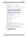
With the ExpressBuilder DVD you can:...................................................................... 193
Software End-User License Agreement ...................................................................... 193
Utilities......................................................................................................................... 193
NEC ESMPRO . . . . . . . . . . . . . . . . . . . . . . . . . . . . . . . . . . . . . . . . . . . . . . . . . . . . . . . . . . . . . . . 194
Functions and Features ................................................................................................ 194
Adaptec Storage Manager‘ - Browser Edition . . . . . . . . . . . . . . . . . . . . . . . . . . . . . . . . . . . . . 195
Features........................................................................................................................ 195
WebPAM . . . . . . . . . . . . . . . . . . . . . . . . . . . . . . . . . . . . . . . . . . . . . . . . . . . . . . . . . . . . . . . . . . . 196
Intel® RAID Web Console 2 Utility (Windows Interface) . . . . . . . . . . . . . . . . . . . . . . . . . . . . . 197
Power Console Plus . . . . . . . . . . . . . . . . . . . . . . . . . . . . . . . . . . . . . . . . . . . . . . . . . . . . . . . . . . 198
Major Functions...........................................................................................................
Components ................................................................................................................
System Setup................................................................................................................
Management PC Setup.................................................................................................
198
198
199
200
SCSISelect Utility . . . . . . . . . . . . . . . . . . . . . . . . . . . . . . . . . . . . . . . . . . . . . . . . . . . . . . . . . . . . 201
Running the SCSISelect Utility ...................................................................................
Adaptec SCSI Utility Configuration Settings..............................................................
SCSI Disk Utilities.......................................................................................................
Exiting Adaptec SCSI Utility ......................................................................................
8
201
201
202
203
User Guide
www.bull.com
HostRAIDTM . . . . . . . . . . . . . . . . . . . . . . . . . . . . . . . . . . . . . . . . . . . . . . . . . . . . . . . . . . . . . . . . 204
Overview of HostRAID ...............................................................................................
Overview of the specifications ....................................................................................
Features........................................................................................................................
References....................................................................................................................
Recommendations and Specifics .................................................................................
204
204
204
205
205
ExpressBuilder . . . . . . . . . . . . . . . . . . . . . . . . . . . . . . . . . . . . . . . . . . . . . . . . . . . . . . . . . . . . . . 206
ExpressBuilder (Windows-Based)............................................................................... 206
Installing the Operating System with Express Setup. . . . . . . . . . . . . . . 207
About Express Setup.................................................................................................... 207
Installing Microsoft Windows Server 2003 . . . . . . . . . . . . . . . . . . . . . . . . . . . . . . . . . . . . . . . 208
Installation Notice........................................................................................................ 208
Installing Windows Server 2003.................................................................................. 210
Updating the System . . . . . . . . . . . . . . . . . . . . . . . . . . . . . . . . . . . . . . . . . . . . . . . . . . . . . . . . . 211
Installing Drivers or Software . . . . . . . . . . . . . . . . . . . . . . . . . . . . . . . . . . . . . . . . . . . . . . . . . . 212
Installing Microsoft Windows Server 2008 . . . . . . . . . . . . . . . . . . . . . . . . . . . . . . . . . . . . . . . 213
Installing Microsoft Windows Server 2003 . . . . . . . . . . . . . . . . . . . . . . . 214
Before Installing Windows Server 2003 . . . . . . . . . . . . . . . . . . . . . . . . . . . . . . . . . . . . . . . . . . 214
Installing Service Pack.................................................................................................
Updating System..........................................................................................................
Re-installing to the Hard Disk which has been upgraded
to Dynamic Disk ..........................................................................................................
Manual Installation when the Disk Array Controllers are Connected.........................
Magneto-Optical device...............................................................................................
Partition Size................................................................................................................
214
214
214
214
214
215
Installing Microsoft Windows Server 2003 . . . . . . . . . . . . . . . . . . . . . . . . . . . . . . . . . . . . . . . . 216
Creating the Windows 2003 OEM-DISK from the ExpressBuilder............................ 216
Windows Server 2003 Installation............................................................................... 217
Reinstallation to Multiple Logical drives .................................................................... 218
Updating the System . . . . . . . . . . . . . . . . . . . . . . . . . . . . . . . . . . . . . . . . . . . . . . . . . . . . . . . . .
Installing Drivers or Software . . . . . . . . . . . . . . . . . . . . . . . . . . . . . . . . . . . . . . . . . . . . . . . . . .
Available Switch Options for Windows Server 2003 Boot.ini File . . . . . . . . . . . . . . . . . . . . .
Collecting the Memory Dump . . . . . . . . . . . . . . . . . . . . . . . . . . . . . . . . . . . . . . . . . . . . . . . . . .
219
220
221
222
Installing Microsoft Windows Server 2008 . . . . . . . . . . . . . . . . . . . . . . . 223
System Security . . . . . . . . . . . . . . . . . . . . . . . . . . . . . . . . . . . . . . . . . . . . . 224
Security with Mechanical Locks and Monitoring. . . . . . . . . . . . . . . . . . . . . . . . . . . . . . . . . . . 225
Front Door Lock .......................................................................................................... 225
Rear Door Padlock Loop ............................................................................................. 225
Software Locks via the BIOS Setup Utility . . . . . . . . . . . . . . . . . . . . . . . . . . . . . . . . . . . . . . . . 226
Using Passwords .......................................................................................................... 226
Maintenance . . . . . . . . . . . . . . . . . . . . . . . . . . . . . . . . . . . . . . . . . . . . . . . . 227
Making Backup Copies. . . . . . . . . . . . . . . . . . . . . . . . . . . . . . . . . . . . . . . . . . . . . . . . . . . . . . . . 227
Cleaning. . . . . . . . . . . . . . . . . . . . . . . . . . . . . . . . . . . . . . . . . . . . . . . . . . . . . . . . . . . . . . . . . . . . 228
Cleaning the External Surfaces of the system ............................................................
Cleaning the Interior of the system..............................................................................
Cleaning the Keyboard ................................................................................................
Cleaning the Mouse .....................................................................................................
Cleaning an Optical Drive and CD-Rom/CD-RW/DVD-Rom....................................
228
229
230
230
230
Care and Handling . . . . . . . . . . . . . . . . . . . . . . . . . . . . . . . . . . . . . . . . . . . . . . . . . . . . . . . . . . . 232
9
User Guide
www.bull.com
Solving Problems . . . . . . . . . . . . . . . . . . . . . . . . . . . . . . . . . . . . . . . . . . . 233
Static Precautions. . . . . . . . . . . . . . . . . . . . . . . . . . . . . . . . . . . . . . . . . . . . . . . . . . . . . . . . . . . . 233
Troubleshooting Guide . . . . . . . . . . . . . . . . . . . . . . . . . . . . . . . . . . . . . . . . . . . . . . . . . . . . . . . 234
System Viewers ........................................................................................................... 234
Lamps........................................................................................................................... 235
Problems at initial System Start-up . . . . . . . . . . . . . . . . . . . . . . . . . . . . . . . . . . . . . . . . . . . . .
Problems After the System Has Been Running Correctly . . . . . . . . . . . . . . . . . . . . . . . . . . .
Problems Running New Application Software. . . . . . . . . . . . . . . . . . . . . . . . . . . . . . . . . . . . .
Problems and Suggestions . . . . . . . . . . . . . . . . . . . . . . . . . . . . . . . . . . . . . . . . . . . . . . . . . . . .
236
237
238
239
Problems with the System............................................................................................
Problems with Windows Server 2003 .........................................................................
Problems with ExpressBuilder.....................................................................................
Problems with Express Setup ......................................................................................
Problems with Disk Array Configuration ...................................................................
Problems with Master Control Menu ..........................................................................
Problems with Disk Array Configuration....................................................................
240
243
245
246
247
247
247
Collecting Event Log . . . . . . . . . . . . . . . . . . . . . . . . . . . . . . . . . . . . . . . . . . . . . . . . . . . . . . . . .
Collecting Configuration Information . . . . . . . . . . . . . . . . . . . . . . . . . . . . . . . . . . . . . . . . . . .
Collecting Dr. Watson Diagnostic Information . . . . . . . . . . . . . . . . . . . . . . . . . . . . . . . . . . . .
Memory Dump (depending on your configuration) . . . . . . . . . . . . . . . . . . . . . . . . . . . . . . . . .
If You Need Assistance . . . . . . . . . . . . . . . . . . . . . . . . . . . . . . . . . . . . . . . . . . . . . . . . . . . . . . .
Error Messages . . . . . . . . . . . . . . . . . . . . . . . . . . . . . . . . . . . . . . . . . . . . . . . . . . . . . . . . . . . . . .
248
249
250
251
252
253
POST Error Messages..................................................................................................
POST Error Beep Codes ..............................................................................................
POST Error Pause Option............................................................................................
Diagnostic LEDs..........................................................................................................
253
255
255
256
Diagnostic LEDs . . . . . . . . . . . . . . . . . . . . . . . . . . . . . . . . . . . . . . . . . . . . . . . . . . . . . . . . . . . . . 260
5V STBY LED.............................................................................................................
Fan Fault LEDs............................................................................................................
System ID LED, System Status LED, and POST Code Diagnostic LEDs..................
DIMM Fault LEDs.......................................................................................................
CPU Fault LEDs ..........................................................................................................
System Status and FRU LEDs .....................................................................................
261
261
261
262
262
262
BIOS Setup Utility . . . . . . . . . . . . . . . . . . . . . . . . . . . . . . . . . . . . . . . . . . . 263
Using the BIOS Setup Utility . . . . . . . . . . . . . . . . . . . . . . . . . . . . . . . . . . . . . . . . . . . . . . . . . . . 263
BIOS Setup Configuration Settings . . . . . . . . . . . . . . . . . . . . . . . . . . . . . . . . . . . . . . . . . . . . . 264
Main Menu...................................................................................................................
Advanced Menu...........................................................................................................
Security Menu..............................................................................................................
Server Management Menu...........................................................................................
Boot Options Menu......................................................................................................
Boot Manager Menu ....................................................................................................
Error Manager Menu ...................................................................................................
Exit Menu ....................................................................................................................
265
266
278
279
281
282
283
284
Updating BIOS. . . . . . . . . . . . . . . . . . . . . . . . . . . . . . . . . . . . . . . . . . . . . . . . . . . . . . . . . . . . . . . 285
Preparing for the Update.............................................................................................. 285
Selecting the BIOS Bank ............................................................................................. 286
Updating the BIOS....................................................................................................... 286
How to Identify BIOS Revision Level . . . . . . . . . . . . . . . . . . . . . . . . . . . . . . . . . . . . . . . . . . . . 288
Recovering BIOS. . . . . . . . . . . . . . . . . . . . . . . . . . . . . . . . . . . . . . . . . . . . . . . . . . . . . . . . . . . . . 289
10
User Guide
www.bull.com
Specifications . . . . . . . . . . . . . . . . . . . . . . . . . . . . . . . . . . . . . . . . . . . . . . 290
Equipment Log. . . . . . . . . . . . . . . . . . . . . . . . . . . . . . . . . . . . . . . . . . . . . . 292
Hardware . . . . . . . . . . . . . . . . . . . . . . . . . . . . . . . . . . . . . . . . . . . . . . . . . . . . . . . . . . . . . . . . . . . 293
Software. . . . . . . . . . . . . . . . . . . . . . . . . . . . . . . . . . . . . . . . . . . . . . . . . . . . . . . . . . . . . . . . . . . . 298
11
User Guide
www.bull.com
Text Conventions
This guide uses the following text conventions.
Warnings, cautions, and notes have the following meanings:
Warning
Warnings alert you to situations that could result in serious personal injury or loss of life.
Caution
Cautions indicate situations that can damage the system hardware or software.
Notes: give important information about the material being
described.
■ Names of keyboard keys are printed as they appear on the keyboard. For example,
Ctrl, Alt, or Enter.
■ Text or keystrokes that you enter appear as boldface type. For example, type
abc123 and press ENTER.
■ File names are printed in upper case letters. For example, AUTOEXEC.BAT.
12
User Guide
www.bull.com
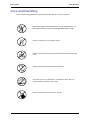
Safety Notices
Caution
To reduce the risk of electric shock which could cause personal
injury, follow all the safety notices.
Symbols are shown in your documentation and on your
equipment to indicate safety hazards.
Regulatory Information
European Notice
Products with the CE marking comply with both the Electromagnetic Compatibility
Directive (2004/108/EEC) and the Low Voltage Directive (2006/95/EEC) - modified
by the Directive 93/68/EEC - issued by the Commission of the European Economic
Community.
Compliance with these directives implies conformity to the following European
Standards:
■ EN55022: Radio disturbance characteristics
■ EN55024 : Immunity characteristics
■ EN6100-3-2: Limitation of harmonic current emissions
■ EN6100-3-3: Limitation of voltage fluctuation and flicker in low-voltage supply
system
■ EN60950-1: Product Safety. If your system includes a telecommunication network
board, the input/output socket is classified as Telecommunication Network Voltage
(TNV-3).
Warning
This is a Class A product. In domestic environment this product
may cause radio interference in which case the user may be
required to take adequate measures (EN55022).
13
User Guide
www.bull.com
USA and Canada Notice
Products with UL marking comply with the following UL standards:
■ UL 1950 (3rd edition 1998)
Products with FCC marking comply with the following FCC standards
■ FCC part 15
The model type/ref. used for UL and FCC certification can be found on the regulatory
labels stuck on your system.
The equipment has been tested and found to comply with the limits for a Class A or B
digital device, pursuant to part 15 of the FCC rules. These limits are designed to
provide reasonable protection against harmful interference when the equipment is
operated in a commercial environment. This equipment generates, uses, and can radiate
radio frequency energy, and if not installed and used in accordance with the instruction
manual, may cause harmful interference to radio communications. Operation of this
equipment in a residential area is likely to cause harmful interference, in which case the
user will be required to correct the interference at his own expense.
Modifications to the Product
CE and FCC Marking
We cannot be held responsible for modifications made by the User and the
consequences thereof, which may alter the conformity of the product with the CE or
FCC Marking.
Connections and Remote Earths
PELV (Protected Extra Low Voltage)
To ensure the extra-low voltage integrity of the equipment, only connect equipment
with mains-protected electrically-compatible circuits to the external ports.
SELV (Safety Extra Low Voltage)
Every input and output of this product is classified as Safety Extra Low Voltage.
Remote Earths
To prevent electrical shock, connect all local (individual office) systems and system
support equipment to the same electrical circuit of the building wiring. If you are
unsure, check the building wiring to avoid remote earth conditions.
Building Supply
Only connect the equipment to a building supply that is in accordance with current
wiring regulations in your country. In the U.K., those are the IEE regulations.
14
User Guide
www.bull.com
Power Supply and Cables
Power Supply
■ The DC push-button on/off switch on the front panel does not turn off the system
AC power. +5vdc is present on the system board whenever the AC power cords are
connected between the system and an AC outlet. Before doing the procedures in
this manual, make sure that your system is powered off and unplug the AC power
cords from the back of the chassis. Failure to disconnect power before opening
your system can result in personal injury and equipment damage.
■ Under no circumstances should the user attempt to disassemble the power supply.
The power supply has no user-replaceable parts. Inside the power supply are hazardous voltages that can cause serious personal injury. A defective power supply
must be returned to your dealer.
Cables
■ In the U.S.A. and Canada, the power cord must be a UL-listed detachable power
cord (in Canada, CSA-certified), type ST or SJT, 16 AWG, 3-conductor, provided
with a moulded-on NEMA type 5-15 P plug cap at one end and a moulded-on cord
connector body at the other end. The cord length must not exceed 9 feet (2.7
meters).
■ Outside the U.S.A. and Canada, the plug must be rated for 250 VAC, 10 amp
minimum, and must display an international agency approval marking. The cord
must be suitable for use in the end-user country. Consult your dealer or the local
electrical authorities if you are unsure of the type of power cord to use in your
country. The voltage change occurs via a switch in the power supply.
■ The detachable power supply cords are intended to serve as the disconnect devices.
■ For PLUGGABLE EQUIPMENT, the socket-outlet shall be installed near the
equipment and shall be easily accessible.
■ This equipment has a 3-wire, grounded power cords. To prevent electrical hazards,
do not remove or defeat the ground prong on the power cords. Replace a power
cord if it gets damaged. Contact your dealer for an exact replacement.
Batteries
Lithium batteries can be dangerous. Improper handling of lithium batteries may result
in an explosion. Dispose of lithium batteries as required by local ordinance. Also see
“Product Disposal” on page 16
Chassis Cover Removal and Replacement
When servicing your system, make sure to replace the chassis cover and secure it with
the screws before plugging in the power cable and turning it on. The chassis cover
ensures proper airflow and cooling.
15
User Guide
www.bull.com
Laser Compliance Statement
The optical devices are tested and certified to be compliant with International Electrotechnical Commission IEC60825-1 and European EN60825-1 standards for Class 1
laser products.
Class 1 laser products are not considered hazardous. The optical devices are designed
such that there is never human access to laser radiation above a Class 1 level during
normal operation or prescribed maintenance conditions.
The optical devices installed in your system are designed for use solely as a component
of such electronic product and therefore do not comply with the appropriate
requirements of Code of Federal Regulation Sec. 1040.10 and Sec. 1040.11 for
COMPLETE laser products
Warning - Hazardous Voltage!
Hazardous voltage is present inside your system when it is connected to an AC supply
even when the system’s power switch is off. Exposure to Hazardous Voltage could
cause personal injury. To reduce the risk of electric shock which could cause personal
injury, follow all safety notices. The symbols shown are used in your documentation
and on your equipment to indicate safety hazards.
Warning -Avoid Electrostatic Discharge!
Circuit cards and integrated circuits can be easily damaged by static electricity. To
reduce risk of damage, store them in protective packaging whenever they are not
installed in your system.
Before you install or remove memory modules, video memory, disk drives, circuit
cards or other devices, protect them from static electricity. To do so, make sure your
system’s power switch is OFF. Then, unplug the system’s AC power cord(s). Wear an
anti-static wrist strap (available at electronic supplies stores) to handle the device you
want to install. Be sure to connect the wrist strap to an unpainted metal portion of the
system chassis.
As an alternative, you can dissipate electrostatic buildup by touching an unpainted
metal portion of the system chassis with one hand. Handle the device you are installing
with the other hand, and maintain continuous contact with the unpainted portion of the
chassis until it is installed in the system.
Product Disposal
The Waste Electrical and Electronic Equipment (WEEE) Directive
requires that used electrical and electronic products must be disposed of
separately from normal household waste in order to promote reuse,
recycling and other forms of recovery and to reduce the quantity of waste
to be eliminated with a view to reducing landfill. WEEE includes
accessories such as keyboard, mouse, remote control, speakers, etc. When you dispose
of such products, please follow the agreement made between you and us and/or your
distributor.
16
User Guide
www.bull.com
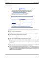
System Features
The NovaScale® T840 is a highly flexible and reliable system designed to offer the
highest levels of performance. It is:
■ based on the Intel® 5000V chipset,
■ designed for the Dual-Core and Quad-Core Intel® Xeon® processors,
■ fitted with higher performance FBDIMM memory,
■ housed in a tower chassis that can also easily be installed into a standard EIA 19inch rack cabinet.
To get comfortable with your computer, take a tour around your system by reading the
sections hereafter.
17
User Guide
www.bull.com
Related Documents
In the ExpressBuilder disc in which you found this User’s Guide, you can also find
several other documents relevant to your system, options and accessories.
Some printed documents may also have been shipped with your system.
We recommend you read these additional documents as it becomes necessary when
setting up, using or upgrading your system.
18
User Guide
www.bull.com
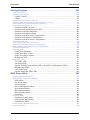
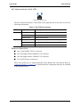
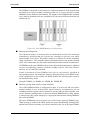
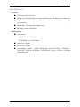
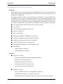
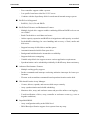
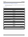
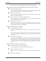
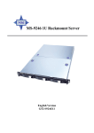
Rear View
A
B
C
D
E
F
H
I
J
G
TP00880
Figure 1: Rear View
A
Power supply bay
Depending on your configuration, it is fitted with a fixed power supply (shown in the picture),
or one with hot-swappable power modules.
B
AC power connector
Connect the power cord to this socket.
C
Alternate SCSI knockout
D
System fan
Keep the area near the venting holes clear for proper ventilation.
E
Connectors
Refer to “Back Panel Connectors” on page 28 for details.
F
Alternate Serial B knockout
G
Expansion boards slots
H
PCI Tool-less card retention mechanism
I
External SCSI knockout
J
Serial B knockout
Refer to the ‘Expansion Boards Slots’ section hererafter for details
19
User Guide
www.bull.com
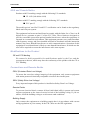
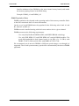
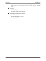
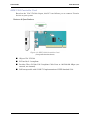
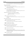
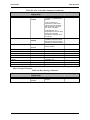
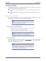
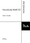
NIC (Network Interface Card) LEDs
Figure 2: NIC Leds
The NIC (Network Interface Card) LEDs at the right and left of each NIC provide the
following information.
Table 1: NIC LED Descriptions
LED
LED State
Description
Left
Off
No network connection
Solid Amber
Network connection in place
Blinking Amber
Transmit/receive activity
Off
10 Mbps connection (if left LED is on or blinking)
Solid Amber
100 Mbps connection
Solid Green
1000 Mbps connection
Right
Expansion Board Slots
■ One 32-bit/33MHz, 5V PCI connector.
■ One full-length 64-bit/100MHz PCI-X connector.
■ One full-length 64-bit/133MHz PCI-X connector.
■ Two x4 PCI Express connectors.
These slots enable you to install additional Video Boards and LAN boards. Refer to
“Optional Features” on page 37 for details about the components that may be installed
in the expansion slots.
20
User Guide
www.bull.com
Status Indicators
This section explains the indication and meanings of the system lamps located on the
front and back panels of your system.
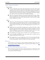
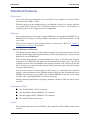
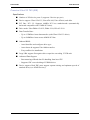
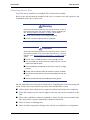
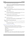
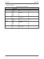
Front Panel
A
B
C
D
E
F
G
H
TP02346
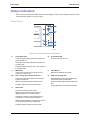
Figure 3: Front panel (front view detail)
A
Power/Sleep LED
B
Continuous green light indicates the system has
power applied to it.
Power/Sleep LED
Powers the system off or on.
Continuous amber light indicates the system is in
S1 Sleep state.
No light indicates the power is off / or the system is
in S4 Sleep state.
C
NMI Button
D
Used to force system halt and dump memory
contents to screen or file.
E/F
Reset Button
Reboots and initializes the system.
NIC 1 Activity LED / NIC 2 Activity LED
G
Hard Drive Activity LED
Continuous green light indicates a link between
system and network.
Random blinking green light indicates hard
drive activity (SCSI or SAS/SATA).
Blinking green light indicates network activity.
Continous amber light indicates a hard drive
fault.
No light indicates the NIC is disconnected.
No light indicates no hard disk drive activity.
H
Status LED
Solid green indicates system ready.
Blinking green indicates that the system is
degraded (processor or memory failure).
Solid amber indicates a critical temperature or
voltage fault, or a missing CPU/terminator.
Blinking amber indicates a power fault, fan fault, or
a non-critical temperature or voltage fault.
No light indicates a fatal error during POST.
21
User Guide
www.bull.com
Back Panel
Network Interface Card (NIC) Ports Activity Lamps
Refer to the back panel description for more details. See “NIC (Network Interface
Card) LEDs” on page 20.
Power Supply LEDs (Hot-Swap Power Supply Only)
Please refer to “Power Supply LEDs” on page 85 for more information.
Diagnostic LEDs
Please refer to “Diagnostic LEDs” on page 256 for more information.
22
User Guide
www.bull.com
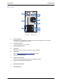
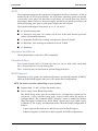
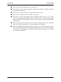
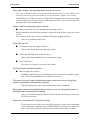
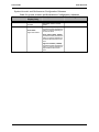
Internal View
A
L
B
C
D
K
E
J
F
G
I
H
TP02033
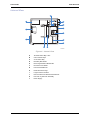
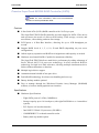
Figure 4: Internal View
A
Tool-less Device Bay Locks
B
5.25-in Device Bays
C
3.5-in Device Bay
D
Drive Bay EMI Shield
E
Drive Cage Retention Mechanism
F
PCI Add-in Card Guide
G
Front Panel USB Ports
H
Fixed Hard Drive Cage
I
Large Processor Air Duct
J
Rear Tool-less PCI Retention Mechanisms
K
Fan Duct / System Fan Assembly
L
Power Supply
23
User Guide
www.bull.com
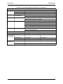
Motherboard
Motherboard Layout
A
B
C D
E
F
G
HI
UU
TT
J
K
SS
L
RR
M
QQ
PP
N
OO
NN
MM
LL
KK
JJ
II
HH
GG
O
P
Q
R
EE CCAA X W
FF DD BB Z Y
VUT
S
AF000173
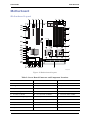
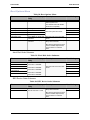
Figure 5: Motherboard Layout
Table 2: Server Board Connector and Component Locations
A.
PCI 32/33 Slot 1
B.
PCIe x4 Slot 3
C.
PCI-X 64/133 Slot 4
D.
PCI-X 64/100 Slot 5
E.
PCIe x4 Slot 6
F.
Back Panel I/O Ports
G.
Diagnostic LEDs
H.
System ID LED
I.
System Status LED
J.
System Fan 6
K.
System Fan 5
L.
Main Power Connector
M.
Auxiliary Signal Connector
N.
DIMM Sockets
O.
Processor 1 Socket
P.
Processor 2 Socket
Q.
Processor Fan 2 Header
R.
Processor Fan 1 Header
S.
Processor Voltage Regulator
T.
Battery
U.
Processor Power Connector
V.
IPMB Header
W. SAS RAID 5 Key
X.
IDE Connector
Y.
LCP Header
Z.
AA. SAS SGPIO
SAS_SES2
BB. System Fan 3
CC. System Fan 4
DD. System Fan 2
EE. System Fan 1
FF. SATA SGPIO
GG. USB 4-5
24
User Guide
www.bull.com
Table 2: Server Board Connector and Component Locations (Continued)
HH. SATA 0 Connector
II.
SATA 1 Connector
JJ. SATA 2/SAS 0 Connector
KK. SATA 3/SAS 1 Connector
LL. SATA 4/SAS 2 Connector
MM. SATA 5/SAS 3 Connector
NN. Backplane Connector B
OO. Front Panel Header
PP. Backplane Connector A
QQ. USB 6
RR. SATA RAID 5 Key
SS. Speaker
TT. Serial B EMP Connector
UU. Chassis Intrusion
CMOS and Password Clear Jumpers
CMOS
CLR
2
3
PASSWORD
CLR
Default
Default
2
CLEAR
CMOS 3
CLEAR
PASSWORD
J1J2
J1J1
AF000187
Figure 6: CMOS and Password Clear Jumpers
Table 3: CMOS and Password Clear Jumper Descriptions
Jumper Name
Jumper Purpose
CMOS Clear
If pins 2-3 are jumpered, the CMOS settings will be cleared on the
next reset. These pins should be jumpered on 1-2 for normal
operation.
Password Clear
If pins 2-3 are jumpered, administrator and user passwords will be
cleared on the next reset. These pins should be jumpered on 1-2
for normal operation.
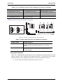
Clearing the Password
If the user or administrator password(s) is lost or forgotten, moving the password clear
jumper into the "clear" position clears both passwords. The password clear jumper
must be restored to its original position before a new password(s) can be set.
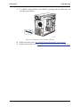
1. Power down the system and disconnect the AC power.
25
User Guide
www.bull.com
2. Open the server chassis.
3. Move the jumper (J1J2) from the normal operation position on pins 1 and 2
(Password Clear Protect), to the pins 2 and 3 (Password Clear Erase position),
as indicated in the following diagram.
CMOS
CLR
PASSWORD
CLR
Default
2
Default
2
CLEAR
CMOS 3
3
J1J1
CLEAR
PASSWORD
J1J2
AF000187
Figure 7: Password Clear Jumper
4. Reconnect the AC power, power up the system.
5. Power down the system and disconnect the AC power.
6. Return the Password Clear jumper to the Password Clear Protect position,
covering pins 1 and 2.
7. Close the server chassis.
8. Reconnect the AC power and power up the server.
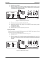
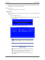
Clearing the CMOS
If you are not able to access the BIOS setup screens, the CMOS Clear jumper will need
to be used to reset the configuration RAM.
1. Power down the system and disconnect the AC power.
2. Open the server.
3. Move the jumper (J1J1) from the normal operation position (pins 1 and 2) to
pins 2 and 3 (CMOS Clear Force Erase position), as indicated in the following
diagram.
CMOS
CLR
2
3
J1J1
PASSWORD
CLR
Default
Default
2
CLEAR
CMOS 3
CLEAR
PASSWORD
J1J2
AF000187
Figure 8: CMOS Clear Jumper
26
User Guide
www.bull.com
4.
5.
6.
7.
Reconnect the AC power, power up the system.
When the system begins beeping, power it down and disconnect the AC power.
Replace the jumper on pins 1 and 2.
Close the server chassis.
Reconnect the AC power and power up the system.
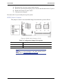
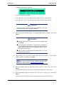
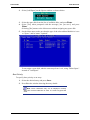
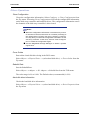
BIOS Select Jumper
This jumper is used to select the BIOS image from which the system will boot.
Figure 9: BIOS Select Jumper (J1J3)
Table 4: Configuration Jumper Descriptions
Pins
Jumper Purpose
1-2
Force BIOS to bank 2
2-3
System is configured for normal operation (bank 1) (Default)
Note: for more information on the BIOS Update process,
please refer to “Updating BIOS” on page 285.
27
User Guide
www.bull.com
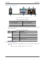
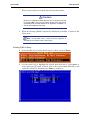
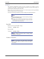
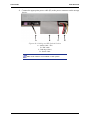
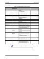
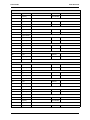
Back Panel Connectors
A
B
H
G
C
D
F
E
AF000184
Figure 10: Back Panel Connectors
Table 5: Back Panel Connectors
A.
Mouse
B.
Serial Port B
C.
NIC 1 (10/100/1000 Mb)
D.
NIC 2 (10/100/1000 Mb)
E.
USB 2-3
F.
USB 0-1
G.
Video
H.
Keyboard
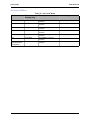
The NIC (Network Interface Card) LEDs at the right and left of each NIC provide the
following information.
Table 6: NIC LED Descriptions
LED
LED State
Description
Left
Off
No network connection
Solid Amber
Network connection in place
Blinking Amber
Transmit/receive activity
Off
10 Mbps connection (if left LED is on or blinking)
Solid Amber
100 Mbps connection
Solid Green
1000 Mbps connection
Right
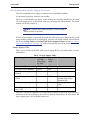
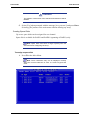
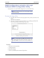
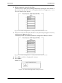
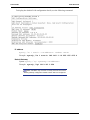
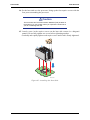
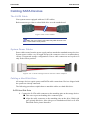
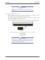
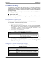
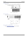
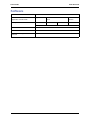
Memory Configuration
The server board provides eight DIMM sockets across two channels, Channel A and
Channel B.
- Channel A consists of DIMM sockets A1, A2, A3, and A4.
28
User Guide
www.bull.com
- Channel B consists of DIMM sockets B1, B2, B3, and B4.
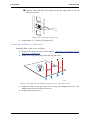
Figure 11: Memory Channels
Memory Modes of Operation
Depending on your DIMM configuration, the server can operate in one of the following
modes:
■ Single-channel mode
This is the minimum possible DIMM configuration. The system will automatically
switch to this mode if only DIMM_A1 is populated.
Note: this single DIMM mode operation
recommended for “performance” applications.
is
not
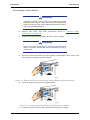
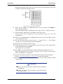
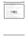
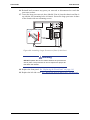
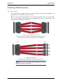
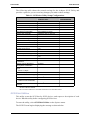
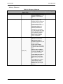
■ Dual-channel mode (maximum interleave mode)
The DIMMs on adjacent channels on each branch are configured for maximum
interleave in order to provide the optimal lock-step operation.
29
User Guide
www.bull.com
The DIMMs in identical socket positions of adjacent channels of the branch must
be identical in terms of timing, technology and size. It is not required to match
DIMMs between different slot numbers. For instance, the DIMM module installed
in A1 must be identical to the one installed in B1, but can be different from the one
installed in A2.
Figure 12: Two DIMM Memory Configuration
■ Memory mirroring mode
Two identical images of memory data are maintained and provide maximum
redundancy, meaning that the system can continue to operate even when
uncorrectable errors occur. The primary image is on Branch 0, and the secondary
image on Branch 1. The controller directs read transactions to the primary branch
while write transactions are directed to both branches under normal circumstances.
All DIMMs on the same DIMM sockets on the adjacent branches must be identical
in terms of technology, number of rancks, timing, and size. The total effective
memory size is reduced by one-half.
Install a minimum of four DIMMs (one pair in each branch, installed in
corresponding slots), and enable the memory mirroring feature in the BIOS Setup.
If the configuration is not suitable, the BIOS disables the mirroring and reverts to
the default memory mode.
Example: DIMM_A1, DIMM_A2, DIMM_B1, DIMM_B2
■ Memory sparing mode (dual or single channel)
One of the DIMM modules is configured as spare. It is reserved, and can replace
another module in case it should fail. Spared memory configurations are not
redundant, and the system cannot continue to operate when an uncorrectable error
occurs. Memory sparing allows to detect an affected DIMM before it fails, replace
it, and preserve the system integrity by copying the data from the failing DIMM to
the reserved DIMM.
The spare DIMM must be at least the size of the largest primary DIMM in use.
When sparing is enabled, the BIOS selects the spare automatically during POST,
and the total effective memory size will be reduced by the size of the spare DIMM.
30
User Guide
www.bull.com
Install a minimum of two DIMMs on the same channel on any branch, and enable
the memory sparing feature in the BIOS Setup.
Example: DIMM_A1 and DIMM_A2.
DIMM Population Rules
DIMM population rules depend on the operating mode of the memory controller. Refer
to the rules mentioned above for more information.
On the server board DIMMs must be populated in the following order: bank A1 and
B1, bank A2 and B2, etc.
DIMMs must be installed starting with the lowest number slot in a given channel.
DIMMs must meet the following requirements:
- Use only Fully Buffered DIMMs (FBD) with DDR2 DRAM technology.
- Use only FBD DDR2-533 and FBD DDR2-667 stacked DIMM modules. The
peak data bandwidth in dual channel mode is 6.4 GB/s (2 x 3.2 GB/s) with
DDR2-533/PC2-4200 and 8.0 GB/s with DDR2-667/PC2-5300.
We recommend you do not mix DIMMs of different speed ratings, even though it is
supported. The overall system memory speed will be determined by the slowest DIMM
populated.
31
User Guide
www.bull.com
Standard Features
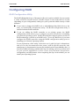
Processor
The system board accommodates up to two Dual-Core or Quad-Core Intel® Xeon®
processors with 2 MB L2 cache.
When two processors are installed, they are of identical revision, core voltage, and bus/
core speed. When only one CPU is installed, it must be in socket 1. No terminator is
required in the case of a single processor configuration.
Memory
The system board provides eight 184-pins DIMM slots each supporting DDR2 533 or
DDR2 667 ECC memory. You may install a minimum of 1 GB and as much as 16 GB
(8 x 2 GB).
Your system supports dual-channel memory architecture. Refer to “Memory
Configuration” on page 28 for details.
Memory Sparing and Mirroring
The chipset includes hardware that supports memory mirroring and memory on-line
sparing. Both memory mirroring and memory on-line sparing provide a way to prevent
data loss in case a DIMM fails.
With memory mirroring the system maintains two copies of all data in the memory
subsystem. If a DIMM fails, the data is not lost because the second copy of the data is
available from the mirrored DIMM in the opposite channel. The system will not fail
due to memory error unless both the primary and the mirrored copy of the data become
corrupt at the same time.
In a mirrored system, the maximum usable memory is one-half of the installed
memory, with a minimum of four DIMMs installed. Since the data is duplicated across
DIMMs, it means that up to one-half of the installed DIMMs are actively in use at any
one time. The remaining DIMMs are used for mirroring.
Memory mirroring and memory sparing are mutually exclusive. Only one can be active
at a time.
Expansion Slots
■ One 32-bit/33MHz, 5V PCI connector.
■ One full-length 64-bit/100MHz PCI-X connector.
■ One full-length 64-bit/133MHz PCI-X connector.
■ Two x4 PCI Express connectors.
Video
The motherboard features the ATI RN50 video controller with 16 MB external video
memory.
32
User Guide
www.bull.com
Network Controller
Note: To ensure EMC product regulation compliance, the
system must be used with a shielded STP/FTP LAN cable.
The motherboard features the Intel® 82563EB dual port controller for 10/100/1000
Mbit/s Ethernet LAN connectivity.
Intel(R) I/O Acceleration Technology
The Intel(R) I/O Acceleration Technology (Intel(R) I/OAT) is a new Intel platform
network technology that accelerates, optimises and seamlessly scales enterprise servers
on Microsoft Windows Server operating systems.
■ Acceleration moves networking data to applications faster.
■ Optimization allows you to increase the load on your servers without increasing
power consumption.
■ Seamless multiple port scaling gives you increased networking throughput from
teaming along with reliable Server and application availability.
Intel(R) I/OAT requires the following to operate on Microsoft Windows Operating
Systems:
■ A server chipset that is Intel(R) I/OAT capable.
■ Microsoft Windows Server 2003 with Service Pack 1or R2 installed.
■ The Scalable Networking Pack from Microsoft.
■ An Intel network connection that is Intel(R) I/OAT capable.
■ The RSS advanced setting must be enabled
■ Both the Offload Receive IP Checksum and Offload Receive TCP Checksum must
be enabled under TCP/IP Offloading Options.
Check to see if the system is capable of using Intel(R) I/OAT and if it is active using the
IOATCHK utility located at the following path:
EXPBUILDER\DRIVERS\NETWORK\INTEL\LANV10.4\PLATFORM\IOATDMA\
WS03/IOATCHK.EXE
To active Intel(R) I/OAT on your system, please apply the activation patch included in
your ExpressBuilder disc. Select the path corresponding to your Microsoft Windows
Server 2003 version.
33
User Guide
www.bull.com
ACPI
The motherboard supports the Advanced Configuration and Power Interface (ACPI) as
defined by the ACPI 2.0 specifications. An ACPI aware operating system can put the
system into a state where the hard drives spin down, the system fans stop, and all
processing is halted. However, the power supply will still be on and the processors will
still be dissipating some power, so the power supply fans will still run.
The system board supports sleep states s0, s1, s3, s4, and s5:
■ s0: Normal running state.
■ s1: Processor sleep state. No context will be lost in this state and the processor
caches will maintain coherency.
■ s3: Suspend to RAM. Your working environment is Saved To RAM.
■ s4: Hibernate. Your working environment is Saved To Disk
■ s5: Shutdown.
Keyboard and Mouse
The keyboard/mouse controller is PS/2-compatible.
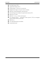
Peripheral Bays
Your system features three 5.25-inch bays that you can use with either a hard disk
drive, an optical device or a tape backup unit.
The 3.5-inch bay may be fitted with an optional floppy disk drive.
RAID Support
Depending on your system, the motherboard features an onboard controller (ESB2-E)
which provides RAID support either for S-ATA and/or SAS configurations.
SATA On-board controller (depending on your system)
■ Supports both 1.5 and 3.0 Gbps data transfer rates.
■ Can be set-up via the BIOS Setup utility.
The BIOS Setup utility provides multiple drive configuration options on the
Advanced > ATA Controller setup page, some of which affect the ability to
configure RAID. The “Onboard SATA Controller” option is enabled by default.
When this option is enabled, the “SATA Mode” option can be set to either Legacy
or Enhanced. The Legacy and Enhanced modes affect the RAID configuration as
follows:
- Legacy supports four disk drives and does not provide RAID support.
- Enhanced supports six disk drives and is required for RAID configurations.
34
User Guide
www.bull.com
■ Provides RAID modes 0, 1, and 10.
For RAID 0, 1, and 10, enclosure management is provided through the
SATA_SGPIO connector on the server board when a cable is attached between this
connector on the server board and to the backplane or I2C interface.
SATA/SAS On-board controller (depending on your system)
In addition to the SATA features described above, SAS models also have a dual-mode
4-port Serial Attached SCSI (SAS) controller that supports both SAS and SATA hard
disk drives.
■ Capable of data transfer rates of up to 3.0 Gbps per port.
■ Supports eight physical drives and eight logical arrays. The SAS controller
supports up to 120 physical drives when expanders are used.
■ Can be set-up via the BIOS Setup utility.
The BIOS Setup utility includes options on the Advanced > Mass Storage setup
page to enable or disable the SAS option ROM and the SAS controller. Both of
these options must be enabled to use RAID.
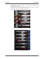
- When the SAS controller is enabled, the two black SATA ports on the server
board continue to function as SATA ports. The four blue ports can be used as
either SAS or SATA ports.
Note: If the SAS option ROM is disabled in the BIOS Setup
utility, but the SAS controller is enabled, the four blue ports on
the server board continue to function as either SAS or SATA
ports and the two black ports on the server board continue to
function as SATA-only ports. However, RAID support is not
available.
- When the SAS controller is disabled in the BIOS Setup utility, only the two
black SATA ports will be available.
When the SAS option ROM is enabled in the BIOS Setup utility, it enables SAS
RAID modes 0, 1, or 10 for the four blue ports on the server board.
■ The SAS controller can mix SAS and SATA drives.
35
User Guide
www.bull.com
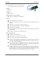
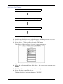
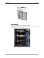
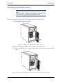
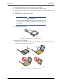
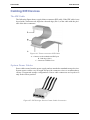
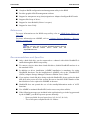
Peripheral Bays
The system supports a variety of standard PC AT-compatible peripheral devices. The
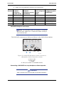
chassis includes these peripheral bays:
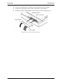
■ Two 5.25-inch file bays for installing half-height 5.25-inch peripheral devices such
as optional tape drives (An optical drive is factory-installed).
A
TP02032
■ One 3.5-inch bay.
■ The hard disk drive cage in which SCSI, S-ATA or SAS hard disk drives can be
installed. Depending on your configuration, the hard disk cage is either fixed or
hot-swappable.
36
User Guide
www.bull.com
Optional Features
You will find hereafter information about the optional components that may be
installed in your system.
This is not an exhaustive list, some options may not be available any more, others may
have been added.
37
User Guide
www.bull.com
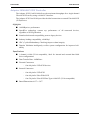
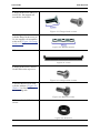
DVD-ROM Drive
Features
■ DVD read speed: 16X max
■ SMART-X Smart Monitoring & Adjusting Read-speed Technology for eXtraction
■ ABS® (Auto Balance System) mechanism to reduce vibration & noise while high
speed rotating
■ Plug & Play with emergency manual eject
■ Belt Tray Loading Mechanism
Specifications
■ Speed (max):
- CD-ROM: 48x (7200 KB/s)
- DVD-ROM: 16x (21600 KB/s)
■ Buffer size: 256 KB
■ Access time: 120 ms
■ Compatibility: ATAPI / E-IDE Half-Height internal DVD+R / DVD+R9 /
DVD+RW / DVD-R / DVD-RW / DVD-ROM / CD-R / CD-RW / CD-ROM
combination drive
38
User Guide
www.bull.com
DVD Writer Combination Drive
Features
■ ATAPI / E-IDE Half-Height internal DVD+R / DVD+RW / DVD-R / DVD-RW /
DVD+R9 / DVD-R9 / DVD-ROM / CD-R / CD-RW / CD-ROM combination
drive.
■ Support Double Layer DVD +/- R9 Recording Function.
■ SMART-BURN avoiding Buffer Under RunError, automatically adjusting writing
strategy and running OPC to provide the best burning quality.
■ SMART-X function adjusts CD-DA / VCD / DVD data extraction to a fastest
allowable speed according to both the data request rate from the host and the disk
quality.
■ ABS® system to reduce vibration and noise during recording and reading.
■ Supports Fixed Packet, Variable Packet, TAO, SAO, DAO, Raw Mode Burning &
Over-Burn.
■ DVD read compliant : DVD single/dual layer ( PTP / OTP ), DVD-R ( 3.9 GB / 4.7
GB ), DVD-R multi-borders, DVD+R, DVD+R multi-sessions, DVD-RW, and
DVD+RW.
■ CD read compliant : CD-DA, CD-ROM, CD-ROM / XA, Photo-CD, Multisession, Karaoke-CD, Video-CD, CD-I FMV, CD Extra, CD Plus, CD-R, and CDRW.
■ Supports both 8 cm and 12 cm CD and DVD discs.
■ Supports Fixed packet, Variable packet, Disc-at-once, Session-at-once and Trackat-once.
■ Transfer modes: PIO mode 4, DMA mode 2 and Ultra DMA mode 4.
Specifications
■ Speed
- DVD+R: 16x max (write)
- DVD+R9: 8x max (write)
- DVD-R: 16x max (write)
- DVD-R9: 4x max (write)
- DVD+RW: 8x max (re-write)
- DVD-RW: 6x (re-write)
- CD-R: 48x (write)
- CD-RW: 24x (re-write)
■ Buffer size: 2 MB (max)
39
User Guide
www.bull.com
■ Access time:
- DVD family: 160 ms
- CD family: 160 ms
■ Power requirements:
- +5v +/-5% and less than 100 mVp-p ripple voltage
- +12v +/-5% and less than 200 mVp-p ripple voltage
40
User Guide
www.bull.com
Sony AIT-1 Turbo Tape Drive (IDE)
Please refer to the documentation on the Tape Online CD for more information.
41
User Guide
www.bull.com
Sony AIT-2 Turbo Backup Unit (IDE)
Please refer to the documentation on the Tape Online CD for more information.
42
User Guide
www.bull.com
LTO 2 Tape Drive (SCSI)
Please refer to the documentation on the Tape Online CD for more information.
43
User Guide
www.bull.com
DAT72 Tape Drive (USB)
Please refer to the documentation on the Tape Online CD for more information.
44
User Guide
www.bull.com
Sony AIT-3 Ex Backup Unit (SCSI)
Please refer to the documentation on the Tape Online CD for more information.
45
User Guide
www.bull.com
Syskonnect single port PCI-E x1 LAN Board
■ Bus interface:
- PCI-Express 1.0a compliant
- x1 PCI-Express Serial Link (adapter can also be operated in x4, x8 and x16
Slots)
- PCI-Express Native Hot Plug according to PCI-Express 1.0a and Advanced
Configuration
■ IEEE Standard
■ 10/100/1000BASE-T
■ Full height bracket
■ TCP, UDP and IP checksum calculation
■ Jumbo frames support
■ TCP segmentation
■ Dynamic Interrupt Moderation
■ Promiscuous Mode/ Multicast support
■ Alert Standard Format (ASF)
■ PXE/ RPL support
■ Advanced Power Management/ Wake on LAN
■ Link Aggregation
■ Redundant Switch Failover
■ PCI Express Hot-Plug
■ Parity
■ Virtual LAN (VLAN) support
■ Virtual Cable TesterTM (VCT)
46
User Guide
www.bull.com
Intel Pro/1000 PT Dual Port LAN Board
Two gigabit copper server connections in a single PCI Express
slot.
Interface
■ PCI Express.
Connectors
■ Two RJ-45.
IEEE standards / network topology:
■ 10BASE-T, 100BASE-TX, 1000BASE-T.
Features
■ Intel® PROSet Utility and Intel® PRO Intelligent Install for easy installation.
■ Intel® lead-free1 technology.
■ Plug and play specification support Standard.
■ Auto-negotiation, full-duplex capable.
■ Integrated media access control (MAC) and physical layer (PHY).
■ Includes a full-height bracket.
■ Cable distance: 100m in Category-5 for 100/1000 Mbps and Category-3 for 10
Mbps.
Network Management
■ Wired for Management (WfM) baseline v2.0 enabled for servers.
■ DMI 2.0 support, Windows Management Instrumentation (WMI) and SNMPmanageable SMBus support.
■ Remote Installation Services (RIS).
■ Diagnostics (loopback, testability, PHY register access).
■ Advanced Configuration and Power Interface (ACPI) 1.0 power management.
■ Wake on LAN support over PCI Express.
■ PXE 2.0 enabled through boot read-only memory (ROM).
Advanced Software Features
■ Adapter Fault Tolerance (AFT).
■ Switch Fault Tolerance (SFT).
■ Adaptive Load Balancing (ALB).
47
User Guide
www.bull.com
■ Fast EtherChannel (FEC).
■ Gigabit EtherChannel (GEC).
■ Teaming support : Scales up to 8 connections.
■ Multiple teams: Supports 4 separate teams, maximum.
■ IEEE 802.3ad (link aggregation control protocol).
■ PCIe Hot Plug/Active peripheral component interconnect (PCI).
■ IEEE 802.1Q VLANs.
■ IEEE 802.3 (z, ab, u, x) flow control support.
■ TCP checksum offload — transmission control protocol (TCP), user datagram
protocol (UDP), Internet protocol (IP).
■ IEEE 802.1p.
■ TCP segmentation/large send offload.
■ Interrupt moderation.
48
User Guide
www.bull.com
Intel Pro/1000 MT Dual Port LAN Board
PCI-X Gigabit Adapter for Copper Networks.
Interface
■ PCI-X.
Connectors
■ Two RJ-45
IEEE standards / network topology:
■ 10BASE-T, 100BASE-TX, 1000BASE-T.
Features
■ Intel® Single DriverTM technology.
■ Backward Compatibility with previous generations of Intel PRO/1000 Network
Adapters.
■ Supports 64- or 32-bit PCI-X 1.0 or PCI 2.2 buses.
■ Remote Management Support (WfM, RIS, SNMP/DMI).
■ IEEE 802.3ab Compatibility.
■ Interrupt Moderation: delivers increased performance while significantly reducing
CPU utilization.
■ Includes a low profile and a full-height bracket.
Network Management
■ Compatible with Fast Ethernet.
■ Gigabit speeds on Category-5 cable networks.
■ Auto-sensing, self-configuring 10/100/1000 Mbps.
■ Advanced Cable Diagnostics: dynamically tests and reports network problems
(error rate, cable length) and automatically compensates for cable issues (cross
over cable, wrong pin-out/polarity).
■ Large Send Off-load/TCP Segmentation Off-load: Compatible with Large Send
Off-load feature of Microsoft Windows Server 2003, 2000 and XP which enables
wire speed performance with low CPU utilization.
■ Expanded Advanced Server Features: Intel® ANS software increases uptime with
redundant, teamed connections and scales bandwidth by balancing network traffic
across multiple server connections. Now offers Switch Fault Tolerance and Test
Switch Configuration to test compatibility and further increase uptime.
49
User Guide
www.bull.com
S-ATA Hard Disk Drive
■ SATA II specification.
■ Capacity: 80GB minimum
■ 7200RPM
■ RAID 0, RAID 1, RAID 5 and RAID 0+1 support
50
User Guide
www.bull.com
SCSI Hard Disk Drive
■ Capacity: 73GB minimum
■ 10000 or 15000 RPM
■ RAID 0, RAID 1, RAID 5 and RAID 0+1 support
51
User Guide
www.bull.com
SAS Hard Disk Drive
■ Capacity: 73GB minimum
■ 15000 RPM
■ RAID 0, RAID 1, RAID 5 and RAID 0+1 support
52
User Guide
www.bull.com
Adaptec 29160ALP SCSI Controller
The Adaptec SCSI Card 29160 delivers the maximum throughput for a single channel
Ultra160 SCSI card by using a 64-bit PCI interface.
The Adaptec SCSI Card 29160 provides the ideal connection to external Ultra160 SCSI
(LVD) devices.
Highlights
■ 160 MByte/sec performance
■ SpeedFlex technology ensures top performance of all connected devices,
regardless of SCSI generation
■ Seamless backwards compatibility protects legacy devices
■ Industry-leading compatibility, reliability*
■ CRC (Cyclical Redundancy Checking) improves data integrity
■ Domain Validation intelligently verifies system configuration for improved reliability
Specifications
■ 1-channel, 64-bit (32-bit compatible), ideal for internal and external hard disk
drive configurations
■ Data Transfer Rate: 160MB/sec
■ External Connectors
- One 68-pin for LVD SCSI devices
■ Internal Connectors
- One 68-pin for LVD SCSI
- One 68-pin for Ultra Wide SCSI
- One 50-pin for Ultra SCSI Bus Type 64-bit PCI (32-bit compatible)
■ Board Dimensions 6.87" x 3.87"
53
User Guide
www.bull.com
Adaptec 29320ALP SCSI Controller
The Adaptec SCSI Card 29320 provides the ideal connection to external Ultra320 SCSI
(LVD) devices.
Highlights
■ Adaptec Seamless Streaming® ; this technology pushes the performance of
Ultra320 SCSI to its theoretical limit by implementing in hardware three new
design advances:
- Ultra Streaming Data Path
- Matrix Command Management
- Rapid Packet Protocol Engine
■ 320 MByte/sec performance per channel
■ Industry-leading compatibility and reliability
Specifications
■ Hardware Features
- 64-bit/ 133 MHz PCI/PCI-X interface
- Compatible with 32-bit PCI slots (thus running in the slower 32-bit mode)
- Single-channel Ultra320 SCSI card.
■ Connectors
- 68-pin internal connector
- 68-pin VHDCI external connector for Ultra320 SCSI (LVD) hard disks drives
■ Physical Specifications
- Size: 16,8cm x 6,4cm
54
User Guide
www.bull.com
LSI SecuRAID 114 SCSI Controller
Highlights
With support for 64-bit addressing and a full RAID feature set, the SecuRAID 114
delivers unsurpassed data throughput and fault tolerance for your mid-range server or
performance workstation.
Designed around LSI Logic's next-generation I/O technology - Fusion-MPT™- the
SecuRAID 114 leverages a streamlined firmware-level programming interface and
advanced hardware designs to offer unequalled I/O efficiency and performance. The
SecuRAID 114 also incorporates a space-saving MD2 (low-profile PCI) form factor,
increasing available space, even in the most limited server and workstation enclosures.
■ One single-channel LSI53C1020 Ultra320 SCSI controller
■ IA-64 ready
■ Intel GC80302 integrated I/O processor
■ 64-bit, 66 MHz PCI
■ PCI 2.2 compliant
■ Integrated 64 MB ECC SDRAM cache memory
■ Advanced management and configuration utilities
■ Supports up to 40 logical drives per controller
■ Auto resume during array reconstruction
■ Background initialization for Quick RAID 5 setup
■ FlexRAID®:
- Online capacity expansion
- Online RAID level migration
Features
■ Disk Array Features
- Supports RAID0/RAID1/RAID5/RAID10/RAID50
- Supports up to 40 logical drives
- Supports hot-swap of failed drives
- Automatic rebuild of hot spare drives
- Auto resume on array reconstruction
■ Hardware Features
- 64-bit / 66MHz PCI interface compliant to PCI Rev2.2
- A 64MB cache memory is soldered on the card.
- Single-channel, PCI RAID controller card with an Ultra 320 SCSI interface
55
User Guide
www.bull.com
- Modes supported: SE or LVD mode, SCSI FAST, ULTRA, ULTRA2, 160M and
320M
■ Connectors:
- one internal 68-pin
- one external VHDCI-68-pin connector
■ Physical & Environmental Specifications
- Size: 16,76 x 6,45 cm
- Operating temperature: up to 55°C
- Voltage: 5V± 0.25V
56
User Guide
www.bull.com
Promise Ultra133 TX2 (IDE)
Specifications
■ Number of ATA device ports: 2 (supports 2 devices per port)
■ Device support: Ultra ATA/133, Ultra ATA/100, Ultra ATA/66, and older
■ PCI Bus: PCI 2.2. Supports 66MHz PCI bus motherboards (automatically
backward compatible with 33MHz PCI slots).
■ Drive mode: Ultra DMA 6/5/4/3/2; DMA 2/1/0; PIO 4/3/2/1/0
■ Data Transfer Rate:
- Up to 133MB/sec burst data transfers (with Ultra ATA/133 drives)
- Up to 266MB/sec burst across 66MHz PCI bus
■ Onboard BIOS:
- Auto-identifies and configures drive type
- Auto-detects & supports Ultra Mode transfers
- Easy conflict-free installation
■ Large LBA support: Recognizes drive capacities exceeding 137GB each
■ Advanced Data Support:
- Bus mastering offloads data I/O handling from host CPU
- Supports CRC error-checking of UDMA drives
■ Device support: Dual IDE ports support separate timing and optimum speeds of
attached drive(s) or ATAPI device(s)
57
User Guide
www.bull.com
Promise SuperTrack EX8350 RAID Controller (SATA)
Notes: For more information, refer to the documentation
included on the ExpressBuilder DVD.
Features
■ 8-Port Serial ATA (SATA) RAID controller with 3.0 Gb/s per port.
The SuperTrak EX8350 RAID controller provides support for SATA 3Gb/s drives
and and meets the needs of disk-to-disk backup, NAS storage, security and
surveillance, video editing, and near-line storage.
■ PCI-Express x 4 Host Bus Interface, allowing for up to 1GB throughput per
second.
■ Support RAID levels 0, 1, 5, 6, 10, 50 and JBOD (depending on your server
configuration).
■ Online capacity expansion and RAID level migration to add capacity as needed.
■ Hardware-accelerated RAID 6 Capable for maximum reliability.
The SuperTrak EX8350 delivers multi-drive performance by taking advantage of
Intel's XScale 80333 I/O processor technology. It offers advanced RAID 6
technology for high level fault tolerance, allowing multiple simultaneous drive
failures without downtime or data loss.
■ Multiple logical drive support.
■ Automatic/manual rebuild of hot spare drive.
■ PerfectRAID technology for robust error handling and recovery.
■ Battery backup module optional.
■ Easy to manage through the Web-based Promise Array Manager (WebPAM)
software, a browser-based graphical user interface.
Specifications
■ Hardware Specifications.
- Eight SATA ports at 3.0Gb/s (300MB/sec).
- Storage capacity up to 16.0 terabytes (with eight 500GB drives x 4 controllers/
system).
- PCI-Express x 4 host bus interface.
- Intel IOP333 XScale I/O processor (500 MHz).
- 128MB DDR ECC on-board controller cache.
- Battery back-up module option.
58
User Guide
www.bull.com
- Four controller support within a system.
- Low profile form factor ideal for 1U/2U server.
- Combine with the SuperSwap 4100 for an advanced internal storage system.
■ RAID Levels Supported.
- RAID 0,1,5,6,10, 50 and JBOD.
■ RAID Fault Tolerance and Robustness Features.
- Multiple logical drive support enables combining different RAID levels on one
set of disks.
- Read Check table to avoid data read errors.
- Online capacity expansion and RAID level migration to add capacity as needed.
- PerfectRAID technology for error handling and recovery of fatal, media and
disk errors.
- Support hot swap of failed drives and hot spares.
- Automatic/manual rebuild of hot spare drive.
- Background initialization for instant drive availability.
- Supports bad sector remapping.
- Variable stripe block size support to meet various application requirements.
- Synchronization can be scheduled periodically for RAID array data consistency.
■ Advanced Performance Features.
- Multiple caching policy support.
- Packet commands and interrupt coalescing minimize interrupts for better performance.
- Elevator seek streamlines commands based upon data location on the disk.
■ Web-based Promise Array Manager.
- Creates, deletes, expands, and converts disk arrays remotely.
- Array synchronization and rebuild scheduling.
- Monitors drive, array, and enclosure status and provides online event logging.
- E-mail notification of drive, array, controller or enclosure events (e.g. error or
degrade conditions).
■ SuperBuild BIOS.
- Array configuration utility at the BIOS level.
- BIOS Boot Specification support: boot system from any array.
59
User Guide
www.bull.com
LSI 8704 SAS RAID Controller
Notes:
■ For more information, refer to the documentation included
on the ExpressBuilder DVD-ROM.
■ Before installing this card, make sure that your motherboard
is fitted with 667MHz SDRAM FBDIMMs. Malfunctions may
otherwise occur.
Features
■ One internal SAS port.
■ PCI Express performance up to 2.5 Gbits/s per lane.
■ Online RAID level migration.
■ Drive migration: Drive migration is the transfer of a set of hard drives in an
existing configuration from one controller to another. The drives must remain on
the same channel and must be reinstalled in the same order as in the original
configuration. The controller to which you migrate the drives cannot have an
existing configuration.
■ Drive roaming: drive roaming occurs when the physical disks are changed to
different ports on the same controller. When the drives are placed on different
channels, the controller detects the RAID configuration from the configuration
data on the drives.
Configuration data is saved in both the NVRAM on the RAID controller and on
the hard drives attached to the controller. This maintains the integrity of the data on
each drive, even if the drives have changed their target ID.
■ Patrol read.
■ User-specified rebuild rate.
■ Hardware clustering support on the board.
■ 32 Kbyte nonvolatile random access memory (NVRAM) for storing RAID system
configuration information; the MegaRAID SAS firmware is stored in flash ROM
for easy upgrade.
Specifications
■ Hardware Specifications:
- LSISASA1078 with Integrated PowerPC processor.
- PCI Express 1.0a compliant.
- 2.5 Gb/s per lane.
- x4, x8 and x16 lane width.
60
User Guide
www.bull.com
- Cache memory of 128MB DDRII 667MHz SDRAM.
■ RAID Levels Supported:
- RAID Levels 0, 1, 5, 6, 10, 50, and 60.
■ Configuration software: MegaRAID Management Suite. Refer to “RAID
Configuration using the MegaRAID Configuration Utility” on page 126.
- Online.
- MegaRAID Storage Manager.
- MegaCLI (Command-line Interface).
- Pre-Boot.
- MegaRAID BIOS Configuration Utility.
61
User Guide
www.bull.com
LSI 8708EM2 SAS/SATA RAID Controller
Features
■ 8 SAS/SATA compatible ports
■ Optional battery backup module
■ Optional RAID5/6 key activation
■ Connect up to 16 intermixed SAS
and SATA devices within the same
array
■ Auto-resume on array rebuild
■ Auto resume array reconstruction
■ Online Capacity Expansion
■ Comprehensive management tools
■ Audible alarm circuit
Specifications
■ Hardware Specifications:
- LSI SAS 1078 RAID Chip
- PCI Express compliant.
- 3 Gb/s per lane.
- x8 lane width.
- Cache memory of 128MB or 256MB DDRII 667MHz SDRAM (depending on
your configuration).
■ RAID Support:
- RAID Levels 0, 1, 10.
- RAID Levels 0, 1, 10, 5, 6 and 50 with the optional activation key.
■ Configuration software: MegaRAID Management Suite. Refer to “RAID
Configuration using the MegaRAID Configuration Utility” on page 129.
- Online: MegaRAID Storage Manager Software.
- Pre-Boot: MegaRAID BIOS Configuration Utility (WebBIOS).
Notes:
For more information, refer to the documentation included on
the ExpressBuilder DVD-ROM.
62
User Guide
www.bull.com
Emulex 1150 Fiber Channel Card
Use this fiber channel card to connect your server to a storage library.
For more information, please refer to the documentation on the SAN Storage Builder
CD shipped with the storage unit.
63
User Guide
www.bull.com
IEEE 1394 Controller Card
Based on the VIA VT6306 chipset, this PCI card allows you to connect Firewire
devices to your system.
Features & Specifications
Figure 13: IEEE 1394 Controller Card
(Low profile bracket shown)
■ Chipset VIA VT6306
■ PCI bus Rev2.2 compliant.
■ Provides Three P1394a Full Compliant Cable Ports at 100/200/400 Mbps (two
external, one internal).
■ Full Interoperable with i.LINK ™ Implementation of IEEE Standard 1394.
64
User Guide
www.bull.com
RAID 5 Activation Key
Depending on your configuration, a RAID 5 activation key may have been plugged on
your server motherboard. Refer to the “Motherboard Layout” on page 24 to locate the
connector (referenced as “RR” on the drawing).
This activation key allows you to setup your hard disk drives in a RAID 5
configuration. For more information about RAID 5, refer to “Configuring RAID” on
page 94.
To configure your disk array, follow the procedure described in “RAID Configuration
using the Intel® Embedded Server RAID BIOS Configuration Utility” on page 99.
65
User Guide
www.bull.com
Setting Up Your System
This chapter describes how to select a site, unpack the system, make cable connections,
and power on the system units. Information on front and rear panel features, switches
and LEDs are also included in this chapter.
66
User Guide
www.bull.com
Setting Up Your Server (Rack)
This chapter describes how to select a site, unpack the system, make cable connections,
and power on the system units. Information on front and rear panel features, switches
and LEDs are also included in this chapter.
Setup Flow.
Selecting t
Select a suitable site for the server. Assemble the 19-inch rack assembly.
Unpack the server and accessories from the shipping carton box.
Install the server into the rack assembly.
Connect peripheral devices to the server.
Connect the power cord to the server.
Power on the server to start software setups. Setups depend on the optional internal devices installed and
the peripheral devices connected.
If no operating system was factory-installed, install one to the server.
Install the utilities in the provided ExpressBuilder disc.
Making backup copie
After all the system setup procedures are completed, make backup copies of system information.
System information is required for recovering the server from the trouble or after replacing the system
board.
67
User Guide
www.bull.com
Selecting Server Site
To use the server, install it on a standard EIA 19-inch rack assembly.
Refer to the documentation attached to the rack or contact your sales agent for the
installation of the server on the rack.
Warning
Observe the following instructions to use the server safely. Failure to
follow these instructions may result in death or serious personal injury.
See “General Safety Information” on page 138 for details.
■ Do not use the server in any unapproved place.
■ Do not connect the ground line to a gas pipe.
Caution
Observe the following instructions to use the server safely. Failure to
follow these instructions may cause a fire, personal injury, or property
damage. See “General Safety Information” on page 138 for
details.
■ Do not carry or install the server only by a single person.
■ Do not install the server where the load may be concentrated on a specific point.
■ Do not install any component on the server only by a single
person.
■ Do not pull out a device from the rack if the rack is unstable.
■ Do not leave more than one device being pulled out from the
rack.
■ Do not provide the wiring exceeding the rating power.
Do not install the rack in the places listed below. Installing the rack or mounting the
server on the rack in such a place may cause some malfunction to occur.
■ Narrow space from which devices cannot be pulled out from the rack completely
■ Place that cannot bear the total weights of the rack and devices mounted on the
rack
■ Place where stabilizers cannot be installed or where the rack can be installed only
after the practice of proper earthquake-resistant construction
■ Place of uneven or slanting floor
■ Place of drastic temperature change (near a heater, air conditioner, or refrigerator)
68
User Guide
www.bull.com
■ Place where intense vibration may be generated
■ Place where corrosive gas is generated, chemicals are nearby, or chemicals may be
accidentally sprayed over
■ Place where a carpet not subject to anti-static process is laid.
■ Place where some objects may be fallen on the rack
■ Place near a device generating intense magnetic field (such as a TV, radio,
broadcast/communication antenna, power transmission wire, and electromagnetic
crane) is placed (If unavoidable, contact your sales agent to request proper shield
construction.)
■ Place where the power cord of the server must be connected to an AC outlet that
shares the outlet of another device with large power consumption.
■ Place near equipment that generates power noise (e.g., contact spark at power-on/
power-off of commercial power supply through a relay). If you must install the
server close to such equipment, request your sales agent for separate power cabling
or noise filter installation.
69
User Guide
www.bull.com
Setting Up Your System (Tower)
This chapter describes how to select a site, unpack the system, make cable connections,
and power on the system units.
Setup Flow.
Select a suitable site for the system.
Unpack the system and accessories from the shipping carton box.
Connect peripheral devices to the system.
Connect the power cord to the system.
Power on the system to start software setups. Setups depend on the optional internal devices installed and
the peripheral devices connected.
If no operating system was factory-installed, install one to the server.
Install the utilities in the provided ExpressBuilder disc.
Making backup c
After all the system setup procedures are completed, make backup copies of system information.
System information is required for recovering the system from the trouble or after replacing the system
board.
70
User Guide
www.bull.com
Selecting System Site
Warning
Observe the following instructions to use the system safely. Failure to
follow these instructions may result in death or serious personal injury.
See “General Safety Information” on page 138 for details.
■ Do not use the system in any unapproved place.
■ Do not connect the ground line to a gas pipe.
Caution
Failure to follow the instructions listed below may cause a fire, personal injury, or property damage. See “General Safety Information”
on page 138 for details.
■ Do not install the system where the load may be concentrated on a specific point.
■ Do not provide the wiring exceeding the rating power.
Do not install the system in the places listed below, doing so may cause malfunctions to
occur.
■ Place of uneven or slanting floor
■ Place of drastic temperature change (near a heater, air conditioner, or refrigerator)
■ Place where intense vibration may be generated
■ Place where corrosive gas is generated, chemicals are nearby, or chemicals may be
accidentally sprayed over
■ Place where a carpet not subject to anti-static process is laid.
■ Place near a device generating intense magnetic field (such as a TV, radio,
broadcast/communication antenna, power transmission wire, and electromagnetic
crane) is placed (If unavoidable, contact your sales agent to request proper shield
construction.)
■ Place where the power cord of the system must be connected to an AC outlet that
shares the outlet of another device with large power consumption.
■ Place near equipment that generates power noise (e.g., contact spark at power-on/
power-off of commercial power supply through a relay). If you must install the
system close to such equipment, request your sales agent for separate power
cabling or noise filter installation.
71
User Guide
www.bull.com
Unpacking the System
When you receive your system, inspect the shipping containers prior to unpacking.
If the shipping boxes are damaged, note the damage, and if possible, photograph it for
reference.
After removing the contents of the containers, keep the cartons and the packing
materials.
If the contents appear damaged when you unpack the boxes, file a damage claim with
the carrier immediately.
72
User Guide
www.bull.com
System Chassis Features
Front View with Front Bezel
The following figure shows the location of the front system features
Figure 14: Front Viewl
A
5.25-inch bays
B
Refer to “Front Panel” on page 21 for more
information on the buttons and LEDs.
Two 5.25-inch bays, one of which may include a
tape backup unit or optical disc drive.
C
Hard Disks cage
D
Depending on your configuration, this cage either
contains SATA, SCSI or SAS drives, which can be
hot-swappable or fixed.
E
Front panel
USB ports
73
Drives bay access door & lock
User Guide
www.bull.com
Front View without Front Bezel
A
B
C
D
E
TP00882
Figure 15: Front view without front bezel
A
5.25-inch bays
B
One 3.5-inch bay, that may be fitted with a
floppy disk drive (optional).
Two 5.25-inch bays, one of which may include a
tape backup unit, CD-ROM drive, DVD-ROM
drive, DVD-RW drive or COMBO DVD-ROM CDRW drive.
C
Hard Disks cage
D
Depending on your configuration, this cage either
contains SATA, SCSI or SAS drives, which can be
hot-swappable or fixed.
E
3.5-inch bay
Front panel USB ports
74
Drives bay EMI shield (shown open)
User Guide
www.bull.com
Rack Installation Kit Assembly
This section provides the assembly instructions for mounting the server into a standard
19-inch rack cabinet.
Unpacking the Rack Installation Kit
Although the rack installation kit is inspected and carefully packaged at the factory,
damage may occur during shipping. Follow these steps for unpacking.
1. Visually inspect the shipping containers; notify your carrier immediately of any
damage.
2. Carefully remove the rack mounting hardware and verify the parts.
Note: The quantities noted below are subject to change
without notice.
2 sets of support rail assemblies (1 front and 1 rear part for
each)
Figure 16: Rail assembly front and rear parts
(right side shown)
6 (minimum) self-tapping
screws (TCB M5) for support
rails front and rear parts
assembling
Figure 17: Self-tapping screws
6 (minimum) washers, to be
used with the 6 self-tapping
screws ("Figure 17: Self-tapping screws")
Figure 18: Washers for the self-tapping screws
75
User Guide
www.bull.com
8 flange head screws (M5x12)
used to fix the support rail
assemblies to the rack
Figure 19: Flange head screws
4 washer plates, to be used
with the flange head screws to
fix the support rail assemblies
to the rack ("Figure 19: Flange
head screws")
Figure 20: Washer plates
Filler
Figure 21: Filler
4 flange head screws, used to
fix the filler to the top cover
Figure 22: Flange head screws
2 Screws M5x16, to be used
with the washers ("Figure 24:
Washers") to fix the filler to
the mounting rails
Figure 23: M5x16 screws
2 Washers for the M5x16
screws
Figure 24: Washers
76
User Guide
www.bull.com
2 Caged nuts, to be used with
the screws ("Figure 23: M5x16
screws" ) and washers ("Figure
24: Washers") to fix the filler
to the mounting rails
Figure 25: Caged nuts
If some of the parts listed above are missing or if the hardware is damaged, notify your
server representative.
Additional Parts for Future Use
8 (minimum) screws (TCB
M5)
Figure 26: Screws
8 (minimum) washers
Figure 27: Washers
Before You Begin
Before you begin, please review the following cautions, warnings, and general
guidelines.
Warning
Be sure that power to the system is turned off and unplugged.
All voltage is removed only when the power cords are
unplugged.
■ Avoid excessive vibration and shock. Dropping an electronic component can cause
serious damage.
■ Do not disconnect or remove parts other than those specified in the procedure.
■ Do not touch I/O connector pins.
77
User Guide
www.bull.com
■ All screws are Phillips-head, unless otherwise specified.
■ On completion of any assembly or reassembly, perform a power-on test. If a fault
occurs, verify that the assembly or reassembly was performed correctly. If the
problem persists, see “Solving Problems” on page 233.
Static Precautions
An electrostatic discharge (ESD) can damage disk drives, option boards, and other
components. You can provide some ESD protection by wearing an anti-static wrist
strap attached to chassis ground when handling system components.
Electronic devices can be easily damaged by static electricity. To prevent damage, keep
them in their protective packaging when they are not installed in your system.
Assembly
The following subsection describes how to assemble your rack-mount server into a
standard 19-inch rack cabinet.
Before you begin select an appropriate location in your rack cabinet for the rack-mount
server. To improve rack stability, mount heavier items towards the bottom of the rack
cabinet. If the rack is a stand-alone unit and the rack is more than 75% filled with
components, consider installing an optional stabilizer kit.
Note: When planning your system configuration for the rack
cabinet you should consider the length of the cables that interconnect system components.
Warning
■ ANCHOR THE EQUIPMENT RACK: The equipment rack must be
anchored to an unmovable support to prevent it from falling
over when one or more servers are extended in front of it on
slide assemblies. The anchors must be able to withstand a
force of up to 113 kg (250 lbs). You must also consider the
weight of any other device installed in the rack.
■ MAIN AC POWER DISCONNECT: You are responsible for installing an AC power disconnect for the entire rack unit. This
main disconnect must be readily accessible, and it must be
labelled as controlling power to the entire unit, not just to the
server(s).
■ GROUNDING
THE RACK INSTALLATION: To avoid the potential
for an electrical shock hazard, you must include a third wire
safety grounding conductor with the rack installation. If a
server power cord is plugged into an AC outlet that is part of
the rack, then you must provide proper grounding for the
rack itself. If server power cords are plugged into wall AC
78
User Guide
www.bull.com
outlets, the safety grounding conductor in each power cord
provides proper grounding only for the server. You must provide additional, proper grounding for the rack and other
devices installed in it.
Caution
Temperature: The operating temperature of the server, when
installed in an equipment rack, must not go below 5 °C or rise
above 35 °C. Extreme fluctuations in temperature can cause a
variety of problems in your server.
Ventilation: The equipment rack must provide sufficient airflow
to the front of the server to maintain proper cooling. It must also
include ventilation sufficient to exhaust a maximum of 4,100
Btu's per hour for the server. The rack selected and the
ventilation provided must be suitable to the environment in
which the server will be used.
Note: For vertical reference, every three screw holes on the
rack vertical mounting rail are equal to 1U (1.75 inches).
Mounting holes in the vertical rails of equipment racks are commonly spaced in a 5/8 x 5/8 x 1/2-inch sequence. Perform the
following steps carefully; brackets must be mounted with precision to allow room for the next server you install in a rack.
Assembling the Front and Rear Parts of Support Rails
The support rails are made of a front and a rear part. Those two parts may be adjusted
to fit the distance between the front and rear vertical rails of the rack.
1. Assemble the front (A) and rear (B) parts of the right support rail with 3 self
tapping screws (C) and 3 flat washers (D).
Note: When using self-tapping screws, we recommend you
tighten the screw for 3 quarters of a turn, and loosen for 1
quarter. Repeat this cycle until the screw is completely
tightened.
79
User Guide
www.bull.com
2. Adjust the total length to fit the distance between the front and rear vertical
rails of the rack before securing the screws.
Figure 28: Right support rail front and rear parts
3. Assemble the left support rail the same way.
Installing the Support Rails
1. Install the right support rail (A) as shown in illustration.
2. Secure the rail to the front (B) and rear (C) vertical mounting rails with two
flange head screws (D) and the washer plate (E).
F
C
B
A
D
D
E
Figure 29: Installing the right support rail
3. Insert one caged nut (F) as shown in the figure above, in the middle hole of the
sixth U. Insert the caged nut in the front mounting rail as follows (see "Figure
30: Inserting a caged nut"):
■ Position the caged nut on the inside of the front vertical mounting rail.
■ Hook the side lip of a caged nut into the square hole in the rail.
80
User Guide
www.bull.com
■ Push the other side lip of the caged nut into the square hole in the rail
until it is secured.
Figure 30: Inserting a caged nut
4. Repeat steps 1 to 3 for the left support rail.
Installing the Filler on the Server
Install the filler on the server as follows:
1. Remove the right side door as described in “Removing or Installing the Left
side cover” on page 140.
2. Remove the four plastic plugs from the top side cover.
TP02004
Figure 31: Removing the Plastic Plugs from the Top Side Cover
3. Install the filler on the top of the cover using four flangehead screws. The
handles must face the front of the server.
4. Replace the top side cover.
81
User Guide
www.bull.com
Installing the Server in the Rack Cabinet
Warning
The system can weigh up to 23.5 kg. If it contains numerous
optional boards and peripheral devices, it will weigh more. To
avoid personal injury, make sure you have at least one person
help you lift or move the system.
1. Lift the server onto the support rails and slide it toward the rear of the cabinet.
2. Assemble the M5x16 screws ("Figure 23: M5x16 screws") and their assorted
washers ("Figure 24: Washers") as shown in the figure below.
3. Secure the server to the vertical mounting rails by inserting the screws prepared in
step 2 in the caged nuts located in the middle of the sixth U (A).
A
A
Figure 32: Securing the server to the rack cabinet
82
User Guide
www.bull.com
Making Connections
Connect your keyboard, monitor, and mouse. Also connect any external peripheral
devices such as a printer or scanner by following the instructions included with these
devices.
Caution
Damage to the system may result if the keyboard/ mouse cable
is inserted or removed when power is applied to the system.
Inserting a telephone line connector into a LAN RJ-45 port may
result in personal injury and equipment damage.
83
User Guide
www.bull.com
Power Supply
Depending on your configuration, your system features one of the power supplies
described below:
■ A hot-swappable power supply fitted with one or two power supply modules
(implying redundancy features).
■ A fixed power supply.
Connecting the Power Cord(s)
Plug the female end of the AC power cord(s) shipped with your system into the input
receptacle(s) on the rear of your system power supply.
Plug the male end of the power cord(s) into NEMA 5-15R outlet(s) for 100-120 VAC
or NEMA 6-15R outlet(s) for 200-240 VAC.
If a power cord supplied with the system is not compatible with the AC wall outlet in
your region, obtain a suitable power cord that meets the following criteria:
■ The power cord must be rated for the available AC voltage and have a current
rating that is at least 125% of the current rating of the system.
■ The power cord connector that plugs into the wall outlet must be terminated in a
grounding-type male plug designed for use in your region. It must have
certification marks showing certification by an agency acceptable in your region.
■ The power cord connector that plugs into the system must be an IEC- type CEE-22
female connector.
■ The power cord must be less than 1.8 meters (6.0 feet) long.
When connecting the power cord(s) to a power control unit such as a UPS unit, confirm
that the power control unit is powered OFF. Connecting the power cord(s) while power
is supplied to the power control unit may cause a failure.
Warning
Do not attempt to modify or use the supplied AC power cord if it
is not the exact type required.
84
User Guide
www.bull.com
Hot-Swappable Power Supply Features
This hot-swappable power supply consists of two independent modules.
It can function properly with only one module.
However, if two modules are fitted, if one of the power modules should fail, the other
one will supply power to the system until you can change the failed module. The failed
module can be hot-swapped.
Note: Connect both power modules to power outlets to
ensure continuous operation.
When a power module is operating normally, the LED is lit green. Should it fail (or the
power module switched off, or unplugged), a buzzer will sound, and the LED will turn
off. Press the Fan Failure, Overheat and Power Supply Failure button (see “Front
View with Front Bezel” on page 73) on the front panel to turn off the alarm.
Power Supply LEDs
There are two LEDs on the back of the power supply. Refer to the table below for more
information.
Table 7: Power Supply LEDs
Power Supply Condition
Status LED
(AC OK /
Power Supply Fail)
OFF
Green
Green
Power LED
(Power
Good)
Any DC outputs in short
circuit
Green
OFF
DC Fan not spinning
Amber
OFF
Over-Temperature Protection (OTP)
Amber
Green
AC Power Off
AC Power On in Standby
AC ON and all outputs in
Normal
Remarks
OFF
OFF
Green
Power distribution
module board only.
Module OK.
Module protection
only
Send out alert signal
The PSU is protected against over-temperature conditions that may be caused by a
reduction of the fan cooling or an excessive ambient temperature. In OTP mode, the
power supply unit will eventually shut down.
85
User Guide
www.bull.com
Hot-Swapping a Power Module
Warning
Hazardous voltage, current, and energy levels are present
inside the power supply. There are no user-serviceable parts
inside it; servicing of the power supply should be done only by
technically qualified personnel.
1. Observe the safety and ESD precautions listed in “General Safety
Information” on page 138.
2. Remove the power cable from the defective power supply.
Warning
Put on protective gloves before you follow the instructions
below. The power modules are very hot and there is a risk of
severe burns.
3. Press up on the green latch (A) while pulling on the handle (B) to remove the
hot-swap power supply from the chassis.
B
A
TP00856
Figure 33: Removing the Hot Swap Power Supply Module from the Chassis
4. Insert the new hot swap power supply module.
TP00854
Figure 34: Inserting Hot Swap Power Supply Module in Chassis
5. Connect the power cable to the replaced hot swap power supply.
86
User Guide
www.bull.com
Using the System
The following sections describe how to use this system properly and safely, including
an explanation of the system power on/off sequences, what the POST program checks
in the system, and how to perform a forced power shutdown.
When using the system the following precautions should be observed:
■ Make sure you power off the system before connecting or disconnecting cables
between the system and peripheral devices. Connecting or disconnecting the cables
while the system is powered on may cause malfunction or failures within the
system.
■ Verify that the access lamp on the diskette drive is unlit before turning off the
system or ejecting the floppy disk. Turning off the system or ejecting the floppy
disk while the access lamp is lit may damage data being stored on the floppy disk.
■ After turning off the system, wait at least 10 seconds before turning it on again.
Cycling the power immediately may cause malfunction or failures of the system.
■ Before relocating the system, turn off the power and unplug the power cord from
the outlet. Moving the system when it is powered may cause malfunction or
failures of the system.
■ Clean the system regularly. Regular cleaning prevents failures of the system and its
components.
■ Lightning may cause a momentary voltage drop. To prevent this problem, an
uninterruptible power supply unit is recommended.
■ Only use options qualified for the system. A non-qualified option may be mounted
or connected to the system, but it may fail to operate normally or even cause failures. These types of failures are not covered under warranty.
87
User Guide
www.bull.com
Powering On your System
Caution
Never turn off the system before the characters following the
Boot-BIOS logo are displayed on the screen.
Power on your system as follows.
1. Make sure all external devices, such as a video display, keyboard, and mouse
(optional) have been connected, and the power cords are connected.
2. Power on the video display and any other external devices.
Note: If the system power cord(s) is connected to a power
control unit such as an UPS (Uninterruptible Power Supply)
make sure that the power control unit is powered on.
3. If applicable, open the door behind which the power button is located.
4. Press the POWER button to power on the system. The POWER lamp lights
green. If it is does not light, make sure that the ac power cord is connected to a
functional ac power source.
After a few seconds your system begins the internal Power-On Self Tests (POST). The
POST automatically checks the system board, CPU(s), memory, keyboard, mouse, and
most installed peripheral devices. It also displays the start messages of the BIOS setup
utility during execution.
The POST check results should be especially monitored in the following cases:
■ When the system is being used for the first time.
■ When the system appears to fail.
■ When the system beeps many times between power-on and the OS start-up.
■ When an error message appears on the screen.
Note: For error messages that appear on the display unit,
see “Error Messages” on page 253.
88
User Guide
www.bull.com
Caution
Always allow the POST to complete before powering down your
system.
If you have problems powering on your system, see “Solving Problems” on page 233.
If an operating system was factory-installed on your system, you can start using it.
If not, insert the ExpressBuilder disc into the optical disc drive, reboot the system and
follow the screen prompts to run ExpressBuilder.
89
User Guide
www.bull.com
Powering Off your System
When the system is powered on, pressing the power on/off switch on the front panel of
the system turns the power off.
To turn the system power off:
1. Shutdown the operating system (OS). In most cases, this will shut down the
system after a few seconds (the POWER lam turns off). This is called a
software power-off.
If necessary, press the POWER switch on the front of the computer chassis
again to power off the system. The POWER lamp turns off.
2. Power off the peripheral devices.
Note: If the system power cord is connected to a power
control unit such as an UPS (Uninterruptible Power Supply),
refer to the UPS user's guide for proper power-off procedures.
90
User Guide
www.bull.com
Forcing a Power Shutdown
A forced power shutdown can be used when performing a soft power-off or pressing
the power on/off switch does not power off the system.
To perform a forced power shutdown, press on the power on/off switch located on the
front panel of the system for at least 4 seconds to force the system power off.
To power on after a forced shutdown, wait at least 10 seconds and then power on again.
91
User Guide
www.bull.com
Resetting the System
There are two ways to reset the system.
Caution
Resetting the system clears the DIMM memory and the data in
process. To reset the system when it is not frozen, make sure
that no processing is in progress.
■ Soft reset
If the system halts before starting the OS, press and hold Ctrl and Alt and press
Delete. This restarts the system.
■ Hard reset
Press the reset button at the front of the system. (See “Forcing a Power Shutdown” on
page 91.)
92
User Guide
www.bull.com
Configuring Your System
Configuration and setup utilities are used to change your system configuration.
■ RAID Configuration Utilities
Depending on your configuration (SATA, SCSI, both) and on your disk drive
controller, one or several RAID Configuration Software Utilities may be available
on your system. These software utilities may allow you to perform some of the
following actions: configure the RAID level, setup arrays, format the drives, etc.
■ BIOS Setup Utility
You can configure your system, as well as option boards you may add to your
system, using the BIOS Setup Utility. Several unique system parameters are
configured using the BIOS Setup, which is stored in the system FLASH memory.
If your system has been factory configured, the BIOS Setup Utility does not need
to be run unless you want to change the password or security features, add certain
types of option boards or devices, or upgrade your system board.
For more information about the BIOS Setup Utility, see “BIOS Setup Utility” on
page 263.
93
User Guide
www.bull.com
Configuring RAID
RAID Configuration Utility
The RAID (Redundant Array of Inexpensive Devices) option available for your system
is either a RAID controller board, a RAID chipset on the motherboard, or both
(depending on your configuration) which gives your system the added security of fault
tolerance.
■ If you want to change the RAID level or add additional hard disk drives to the
array, use the RAID configuration utility. The RAID configuration utility is
included with the RAID controller.
■ If you are adding the RAID controller to an existing system, the RAID
configuration utility allows you to configure your disk array before reinstalling
your network operating system. The RAID controllers support various versions of
RAID technology (referred to as RAID levels). To use any RAID level, you must
configure the RAID controller using the RAID configuration utility prior to
installing your Network Operating System.
For an explanation of this utility, check this user’s guide for basic informations,
and refer to the documentation that comes with the RAID controller (the
manufacturer’s documentation is generally included on the ExpressBuilder disc). It
describes RAID technology and provides tips on making your array perform well
in your specific application. It also covers array hardware preparation,
configuration, and initialization. After completing the steps in the manual, you can
install your Operating System.
94
User Guide
www.bull.com
RAID Levels
RAID Configuration
RAID 0
RAID 1
RAID 10
RAID 5
Number of required hard disk drives
2
2
4
3
RAID 0 and RAID 1
■ RAID0 (striping)
When a logical drive is striped, the read and write blocks of data are interleaved
between the sectors of multiple disk drives. Performance is increased, since the
workload is balanced between drives or “members” that form the logical drive.
Identical drives are recommended for performance as well as data storage
efficiency. The logical drive's data capacity is equal to the number of drive
members multiplied by the smallest logical drive member's capacity.
RAID 0 Stripe interleaves data across multiple drives For example, one 100GB
and three 120GB drives will form a 400GB (4 x 100GB) logical drive instead of
460 GB.
Warning
■ RAID0 does not have data redundancy. When a hard disk
drive failure occurs, data cannot be restored.
■ Logical capacity of the array becomes a multiple of the connected hard disk drive.
■ RAID1 (mirroring)
When a logical drive is mirrored, identical data is written to a pair of disk drives,
while reads are performed in parallel. The reads are performed using elevator seek
and load balancing techniques where the workload is distributed in the most
efficient manner. Whichever drive is not busy and is positioned closer to the data
will be accessed first.
With RAID 1, if one disk drive fails or has errors, the other mirrored disk drive
continues to function. This is called Fault Tolerance. Moreover, if a spare disk
drive is present, the spare drive will be used as the replacement drive and data will
begin to be mirrored to it from the remaining good drive.
Due to the data redundancy of mirroring, the capacity of the logical drive is only
the size of the smallest disk drive. For example, two 100GB disk drives which
have a combined capacity of 200GB instead would have 100GB of usable storage
95
User Guide
www.bull.com
when set up in a mirrored logical drive. Similar to RAID 0 striping, if disk drives
of different capacities are used, there will also be unused capacity on the larger
drive.
Warning
■ RAID1 reads or writes data to/from the several hard disk
drives at the same time. The disk access performance is
lower than the single disk.
■ Logical capacity of the array is equal to one hard disk drive
connected.
Raid 10 & RAID 5
These RAID levels may also be available on your system. Browse through the next
sections of this User’s Guide for more information.
■ RAID 10
Mirror/Stripe combines both of the RAID 0 and RAID 1 logical drive types. It can
increase performance by reading and writing data in parallel while protecting data
with duplication. At least four disk drives are needed for RAID 10 to be installed.
With a four-disk-drive logical drive, one drive pair is mirrored together then
striped over a second drive pair.
The data capacity is similar to a RAID 1 logical drive, with half of the total storage
capacity dedicated for redundancy. An added plus for using RAID 10 is that, in
many situations, such a logical drive offers double fault tolerance. Double fault
tolerance may allow your logical drive to continue to operate depending on which
two disk drives fail.
96
User Guide
www.bull.com
■ RAID 5
RAID level 5 organizes data across the disk drives of the logical drive, and
distributes parity information across the disk drives along with the data blocks.
This organization allows increased performance by accessing multiple disk drives
simultaneously for each operation, as well as fault tolerance by providing parity
data. In the event of a disk drive failure, data can be re-calculated by the RAID
system based on the remaining data and the parity information.
The adjustable block size of the RAID 5 logical drive allows for performance
tuning based on the typical I/O request sizes for your system. The block size must
be set at the time the logical drive is created and cannot be adjusted dynamically.
RAID 5 makes efficient use of hard drives and is the most versatile RAID Level. It
works well for file, database, application and web servers.
The capacity of a RAID 5 logical drive is the smallest disk drive size multiplied by
the number of disk drives, less one. Hence, a RAID 5 logical drive with four 100
GB disk drives will have a capacity of 300 GB. A logical drive with two 120 GB
disk drives and one 100 GB disk drive will have a capacity of 200 GB.
97
User Guide
www.bull.com
RAID Configuration Using Promise Array
Management
Please refer to the documentation included on the ExpressBuilder disc.
98
User Guide
www.bull.com
RAID Configuration using the Intel® Embedded
Server RAID BIOS Configuration Utility
Description
The Intel® Embedded Server RAID BIOS Configuration utility allows a user to:
■ Create, add, modify, and clear logical drive configurations.
■ Initialize or rebuild the configured drives.
■ Set the boot drive.
■ Create a global hotspare drive.
■ View physical and logical drive parameters.
■ View and set adapter properties, including consistency check and auto-resume.
SATA and SAS systems use different versions of the Intel Embedded Server RAID
BIOS Configuration utility, but both versions use the same keystrokes and contain
identical menus. The utility menus show limited help at the bottom of the screen and
selections are chosen with the arrow keys and the space bar. A warning is displayed if
there is no logical drive available to be configured.
Enabling RAID in the BIOS
RAID should first be enabled in the BIOS before you can configure it. For more
information, refer to “BIOS Setup Utility” on page 263.
Entering the Intel Embedded Server RAID BIOS Configuration Utility
When the SATA RAID or SAS RAID options are enabled in the server BIOS, an option
to enter the Intel Embedded Server RAID BIOS Configuration utility displays during
the server boot process. To enter the utility, press the <Ctrl> + <E> when prompted.
Note: The onboard SAS and SATA RAID features are
optional. Depending on your configuration, they may or may not
be available on your system.
Setting Up the RAID Feature
Please refer to the Intel® Embedded Server RAID BIOS Configuration Utility Software
Guide included on the ExpressBuilder disc for more information.
99
User Guide
www.bull.com
RAID Configuration using SuperBuildTM
Please refer to the Promise SuperTrak EX8350 Disk Array Controller User’s Guide
included on the ExpressBuilder disc for more information.
100
User Guide
www.bull.com
RAID Configuration using the SCSISelect Utility
Installing the Hard Disk Drives
Install the required SCSI hard disk drives to your system.
Caution
■ Use two hard disk drives of the same revolution (rpm).
■ To configure RAID 1, use also two hard disk drives of the
same capacity.
Enabling the RAID Feature using the SCSISelect Utility
Two or more of the installed hard disk drives can be used either as a single disk or a
RAID drive.
Note: The factory-set value is to use the hard disk drive as
a single disk drive.
To configure a disk drive connected to the onboard SCSI connector with the
SCSISelect Utility:
1. Start the SCSISelect Utility. See “Running the SCSISelect Utility” on
page 201.
AIC-7902 A at Slot 23 02:03:00
AIC-7902 B at Slot 23 02:03:01
101
User Guide
www.bull.com
2. Select the channel to set HostRAID to open the Options window.
3. Select [Configure/View SCSI Controller Settings] and press Enter.
4. Select [Disabled] of Host RAID on Configuration menu and press Enter.
5. Change it to [Enabled].
6. Press Esc. The confirmation message [Save Changes Mode?] appears. Select
[Yes].
102
User Guide
www.bull.com
7. Select [Configure/View HostRAID Settings] and press Enter.
8. Select [Configure/View HostRAID] and press Enter.
Main Menu
When you select [Configure/View HostRAID Settings], the Main Menu as shown
below appears upon completion of the device scan.
103
User Guide
www.bull.com
Main Menu Display
ID
Indicates either the SCSI ID of the hard disk drive or the ID of the array.
Type
Indicates the RAID level for the array, and any available disk drive that is not in
the array.
- Hard Drive: Available hard disk drive that is not in the array.
- Striped (R0): Array configured in RAID0.
- Mirrored (R1): Array configured in RAID1.
- Stripe/Mirror (R10): Array configured in RAID 10 (spanning of
RAID1).
- Spare: Hard disk drive assigned as a spare disk.
Vendor
Indicates the manufacturer of the hard disk drive or HostRAID (Adaptec).
Product
Indicates the model name of the hard disk drive or the array name.
Size
Indicates the capacity of the hard disk drive or that of the array.
Status
Indicates the status of the hard disk drive or array.
- Free: Available hard disk drive that is not in the array.
- Optimal: Array is in normal state.
- Degraded: One of the RAID1 or RAID10 hard disk drives is failed.
- Dead: One or more RAID0 hard disk drives is failed.
Two or more RAID1 or RAID10 hard disk drives are failed.
- Building: The array is in build process.
- Verify: The array is in verify process.
- Rebuild: The array is in rebuild process.
104
User Guide
www.bull.com
When you select the array on Main Menu, the detailed information of the hard disk
drives in array is displayed.
Detailed indications
ID
Indicates the SCSI ID of the hard disk drives that configures the array
Type
Indicates the RAID level for the array.
- Striped (R0): Array configured in RAID0
- Mirrored (R1): Array configured in RAID1
- Stripe/Mirror (R10): Array configured in RAID 10 (spanning of
RAID1)
Vendor
Indicates either the manufacturer of the hard disk drive or HostRAID (Adaptec).
Product
Indicates the model name of the hard disk drive or the array name.
Size
Indicates the capacity of the hard disk drive or that of the array.
Status
Indicates the status of the hard disk drive or that of the array.
- Optimal: the hard disk drive is operating normally.
- Degraded: the hard disk drive is degraded.
- Failed: the hard disk drive is failed.
- Building: the hard disk drive is being built.
- Verify: the hard disk drive is being verified.
- Replaced: the hard disk drive is being rebuilt.
- Missing: the hard disk drive is hidden from the controller.
Exiting the Utility
To exit the utility, press Esc until a message prompts you to exit.
105
User Guide
www.bull.com
Select [Yes] to exit and press any key to restart the computer. The changes you have
made become valid after the system restarts.
Creating Arrays
Follow the procedures below to create an array.
Requirements
Before creating arrays, make sure the disks for the array are connected and installed in
your system.
1. Start the SCSISelectUtility.
Select [Configure/View HostRAIDSettings] from Options menu of the channel
to create an array.
2. Press C on the main menu to create an array..
Note: Some characters may not be displayed correctly
when the console redirection is used. It is safe to bypass this
issue.
Caution
■ At least two hard disk drives are required to create an array.
■ If hard disk drives of different capacities are used, the array
capacity is determined according to the smaller one.
■ Use only hard disk drives which models are supported by
the system.
106
User Guide
www.bull.com
■ The hard disk drive which has been configured as an array
disk drive cannot be selected.
3. Select a RAID type in [Select RAID Type] window and press Enter.
Put a cursor to the selected item, another window opens indicating the
minimum and maximum number of disks to create an array and a message for
assigning a spare disk.
Note: To set the RAID level, see or “Creating RAID1 Array”
on page 109 and “Creating RAID0 Array” on page 107.
Caution
After creating an array, set the boot priority for the created array
according to "Boot Priority".
Creating RAID0 Array
To create a RAID0 array:
1. Select [RAID-0] on the [Select RAID Type] window.
107
User Guide
www.bull.com
2. Use the cursor key to highlight the desired hard disk drives, press Space to
select them (an [X] mark is placed next to the selected hard disk drive) and
when the selection is finished, press Enter to validate it.
.
3. Select the desired stripe size and press Enter. Available stripe sizes are 16, 32,
and 64 KB.
4. Enter the desired RAID Name in [Assign RAID Name] window and press
Enter.
Caution
■ A RAID Name must be unique, and up to 15 characters are
acceptable.
■ If a valid partition information or a boot block is detected in
the selected hard disk drive, a warning message will be displayed. Select [Yes] to continue creating an array, or [No] to
cancel the array creation.
■ Take to select the appropriate hard disk drives. If not, the
data will not be restored.
5. The message "Do you want to make this array as bootable?". Select either
[YES] or [NO], and then press Enter.
Note: The boot priority can be changed after the arrays
have been created. Refer to “Boot Priority” on page 115.
6. When prompted with the message [Create Array?], select [Yes] and press
Enter.
Selecting [No] cancels the array creation and returns to the Main menu.
108
User Guide
www.bull.com
7. When prompted with the message [Are you sure?], select [Yes] and press
Enter.
Selecting [No] cancels the array creation and returns to the Main menu.
8. When the message [Build Completed] is displayed, press Esc to return to the
Main menu.
Note: On the Main menu, make sure that "Optimal" is
indicated for the status of the created array.
Creating RAID1 Array
To create a RAID1 array, perform either of the followings:
■ Create a new RAID1 array.
■ Migrate to RAID1 array using the data stored in an existing single disk.
(Migration)
Creating RAID1 array using an existing single hard disk drive is called "migration".
During the migration, the source hard disk drive must have been used as the boot disk
in the standard SCSI connection.
Refer to the "HostRAID Setup Card" documentation for details on the migration.
To create a RAID1 array:
1. Select [RAID-1] on the [Select RAID Type] window.
2. Use the cursor key to highlight the desired hard disk drives, press Space to
select them (an [X] mark is placed next to the selected hard disk drive) and
when the selection is finished, press Enter to validate it.
Select one of the options in the [RAID-1 Build Option] window and press
Enter.
109
User Guide
www.bull.com
Available options are as follows:
- Create new RAID-1:Default
- Copy from (X) to (Y):Copy data from the disk of ID X to that of ID Y.
- Copy from (Y) to (X):Copy data from the disk of ID Y to that of ID X.
Caution
Double-check the copy source and copy destination. If they are
incorrect, the data will no longer be restored.
3. Enter the desired RAID Name in [Assign RAID Name] window and press
Enter.
Caution
■ A RAID Name must be unique, and up to 15 characters are
acceptable.
■ If a valid partition information or a boot block is detected in
the selected hard disk drive, a warning message will be displayed. Select [Yes] to continue creating an array, or [No] to
cancel the array creation.
■ Take to select the appropriate hard disk drives. If not, the
data will not be restored.
4. The message "Do you want to make this array as bootable?". Select either
[YES] or [NO], and then press Enter.
Note: The boot priority can be changed after the arrays
have been created. Refer to “Boot Priority” on page 115.
5. When prompted with the message [Create Array?], select [Yes] and press
Enter.
Selecting [No] cancels the array creation and returns to the Main menu.
6. When prompted with the message [Are you sure?], select [Yes] and press
Enter.
Selecting [No] cancels the array creation and returns to the Main menu.
110
User Guide
www.bull.com
When an array has been created, the build operation starts.
Caution
Be sure to complete the Build process. Do not stop the process
by pressing Esc. The OS only detects arrays which have been
completely built, and their status set to "Optimal". In addition, no
OS can be installed in that array.
7. When the message [Build Completed] is displayed, press Esc to return to the
Main menu.
Note: On the Main menu, make sure that "Optimal" is
indicated for the status of the created array.
Creating RAID10 Array
1. Select [RAID-10] on [Select RAID Type] window and press Enter.
2. Use the cursor key to highlight the desired hard disk drives, press Space to
select them (an [X] mark is placed next to the selected hard disk drive) and
when the selection is finished, press Enter to validate it.
111
User Guide
www.bull.com
3. Select the desired stripe size and press Enter. Available stripe sizes are 16, 32,
and 64 KB.
4. Enter the desired RAID Name in [Assign RAID Name] window and press
Enter.
Caution
■ A RAID Name must be unique, and up to 15 characters are
acceptable.
■ If a valid partition information or a boot block is detected in
the selected hard disk drive, a warning message will be displayed. Select [Yes] to continue creating an array, or [No] to
cancel the array creation.
■ Take to select the appropriate hard disk drives. If not, the
data will not be restored.
5. The message "Do you want to make this array as bootable?". Select either
[YES] or [NO], and then press Enter.
Note: The boot priority can be changed after the arrays
have been created. Refer to “Boot Priority” on page 115.
6. When prompted with the message [Create Array?], select [Yes] and press
Enter.
Selecting [No] cancels the array creation and returns to the Main menu.
7. When prompted with the message [Are you sure?], select [Yes] and press
Enter.
Selecting [No] cancels the array creation and returns to the Main menu.
8. When the message [Build Completed] is displayed, press Esc to return to the
Main menu.
Deleting Arrays
To delete an array:
Caution
Before deleting an array, back up the hard disk drive data.
Deleted arrays cannot be restored.
1. On the main menu, highlight the array you wish to delete and press Enter.
112
User Guide
www.bull.com
2. Press D on the screen shown below.
Note: Some characters may not be displayed correctly
when the console redirection is used. It is safe to bypass this
issue.
3. Select [Yes] when prompted with the message [Delete Array?] and press Enter.
Selecting [No] returns to the main menu without deleting any array.
4. Depending on your RAID level:
■ <RAID0>
The [Deleting information] window appears, select the hard disk drive
from which you wish to delete a partition or boot block, or select [None],
then press Enter.
<Example>
Drive ID 0:Data in drive 0 is entirely erased. Data in drive 1 is reserved.
Drive ID 1:Data in drive 1 is entirely erased. Data in drive 0 is reserved.
Drive ID 0 & 1:All the data in both drives is erased.
None:Array is deleted, but the data is reserved in both drives.
■ <Other than RAID0>
The [Deleting information] window is not displayed, proceed to the next
step.
113
User Guide
www.bull.com
Caution
The partition or boot block of the selected hard disk drive will be
deleted.
5. Select [Yes] when prompted with the message [Are you sure?] and press Enter.
Selecting [No] returns to the main menu without deleting any array.
Creating Spare Disks
Up to two spare disks can be assigned for one channel.
Spare disk is available for RAID1 and RAID10 (spanning of RAID1) only.
Note: Spare disks must have a larger capacity than the
hard disk drives configuring the array.
To assign a spare disk:
1. Press S on the Main Menu.
Note: Some characters may not be displayed correctly
when the console redirection is used. It is safe to bypass this
issue.
114
User Guide
www.bull.com
2. Select [Add Spare] on the Option window as shown below.
3. Select the spare disk from the list of available disks, and press Enter.
4. Select [Yes] when prompted with the message [Are you sure?] and press
Enter.
Selecting [No] returns to the Main menu without assigning any spare disk.
5. On the Main menu, make sure that the type of the selected hard disk drive is set
to "Spare", and its status "Optimal".
To un-assign a spare disk, take the same steps from 1 to 4, using "Delete Spare"
instead of "Add Spare".
Boot Priority
To specify boot priority to an array:
1. Select the desired array, and press Enter.
2. Press B on the window showing the array details.
Note: Some characters may not be displayed correctly
when the console redirection is used. It is safe to bypass this
issue.
115
User Guide
www.bull.com
RAID Configuration using the MegaRAID
Configuration Utility
Please refer to the documentation included on the MegaRAID Ultra 320 Disk Array
Controller disc.
116
User Guide
www.bull.com
RAID Configuration using the LSI Logic
Software RAID Configuration Utility
Use this utility to set up the RAID configuration of your hard disk drives.
Note: This utility cannot be run via the remote console
feature of DianaScope.
Running the Setup Utility
1. Press Esc when the full screen logo appears after you have powered on the
server.
The POST screen appears.
2. Check the description shown on the POST screen, and then press Ctrl + M.
The LSI Logic Software RAID Setup Utility starts.
Figure 35: LSI Logic Software RAID Configuration Utility
TOP Menu (Management Menu)
Note: To exit the utility, press Esc in the TOP menu of LSI
Logic Software RAID Setup Utility. Select Yes, and then press
Ctrl + Alt + Delete to reboot the server when prompted to do
so.
Tree Menu
+: Selection/execution parameter
←: Setting parameter.
•: Information display
>: Can be set (modified) after creation of logical drive
117
User Guide
www.bull.com
Table 8: Tree Menu
Menu
Description
+Configure
Performs Configuration settings
+Easy Configuration
Set configuration (Using fixed value)
+New Configuration
Set new configuration
+View/Add Configuration
Additional setting / viewing configuration
+Clear Configuration
Clear configuration
+Select Boot Drive
Chose Bootable Logical Drive
+Initialize
Initialize logical drive
+Objects
Various settings
+Adapter
+Sel. Adapter
Set disk array controller
Clear configuration
←Rebuild Rate
30
←Chk Const Rate
30
←FGI Rate
30
←BGI Rate
30
←Disk WC
Off
←Read Ahead
On
←Bios State
Enable
←Stop on Error
No
←Fast Init
Enable
←Auto Rebuild
On
←Auto Resume
Enable
←Disk Coercion
1GB
←Factoty Default
+Logical Drive
Logical drive operation
+Logical Drives
Select logical drive (when multiple logical drives exist)
+Initialize
Initialize logical drive
+Check Consistency
Check logical drive redundancy
+View/Update Parameters
Display logical drive information
• RAID
Display RAID level
• SIZE
Display logical drive capacity
• Stripe SIZE
Display stripe size
• #Stripes
Display the number of hard disk drives in logical drive
• State
Display logical drive status
• Spans
• Disk WC
Off: Write through
On: Write back
• Read Ahead
118
User Guide
www.bull.com
Table 8: Tree Menu (Continued)
Menu
Description
+Physical Drive
Physical drive operation
+Physical Drive Selection Menu
Select physical drive
+Make HotSpare
Set as hot-spare disk for auto rebuilding
+Force Online
Make a disk online
+Force Offline
Make a disk offline
+Drive Properties
Display hard disk drive information
• Device Type
Hard disk drive type
• Capacity
Hard disk drive capacity
• Product ID
Hard disk drive model
• Revision No.
Hard disk drive revision
+Rebuild
Perform rebuilding
+Check Consistency
Perform logical drive redundancy check
119
User Guide
www.bull.com
Operating Procedures for the Setup Utility
Creating/Adding a Configuration
Run the LSI Logic Software RAID Setup Utility
Set new configuration information (pack/logical drive settings)
Check the logical drive settings
Initialize logical drive
Perform a Consistency Check
Exit the LSI Logic Software RAID Setup Utility
1. Run the LSI Logic Software RAID Setup Utility.
Select Configure → New Configuration from the TOP menu (Management
Menu).
Select View/add Configuration to add a configuration.
Caution
■ Creating a configuration using the New Configuration menu
clears any existing configuration information. To add configuration information to an existing configuration, select View/
add Configuration.
■ You cannot create a Spanning of RAID1 or set the logical
drive capacity on the Easy Configuration menu.
Use the New Configuration or View/Add Configuration
instead.
120
User Guide
www.bull.com
2. When prompted to proceed, select Yes.
The Scan Device starts (the scanning information is displayed at the bottom of
the screen). Once the Scan Device is completed, the New Configuration - Array
Selection Menu screen appears.
Figure 36: New Configuration - Array Selection Menu screen
3. Move the cursor onto the hard disk drive to be packed by using the cursor key
and then press Space to select it.
The display for the selected hard disk drive changes from Ready to Online.
Figure 37: New Configuration - Array Selection Menu screen
4. Press F10 to set Select Configurable Array(s).
5. Press Space.
SPAN-1 is set.
Figure 38: Select Configurable Arrays screen
121
User Guide
www.bull.com
6. Press F10 to create a logical drive.
The Logical Drives Configure screen appears. (The figure below shows an
example of a RAID1 configured with two hard disk drives.)
Figure 39: Logical Drives Configure screen
7. Select RAID, Size, DWC, RA, or Span by using cursor keys. Then press Enter
to fix the selection and set each value.
(1) RAID: Sets the RAID level.
Parameter
Remarks
0
RAID0
1
RAID1
10
Spanning of RAID1
The selectable RAID level varies depending on the number of hard disk drives
that configure a pack.
(2) Size: Sets the logical drive size.
Up to 40 logical drives can be created per disk array controller.
(3) DWC: Sets the parameter for the Disk Write Cache.
Parameter
Remarks
Off
Write through
On
Write back
(4) RA: Sets the parameter for the Read Ahead.
Parameter
Remarks
Off
Does not perform read ahead
On
Performs read ahead
(5) Span: Sets the Span.
Parameter
Remarks
SPAN=NO
Does not set span
SPAN=YES
Sets span
122
User Guide
www.bull.com
When performing a Span, create two or more sets of the same pack at the pack
creation, as shown in the figure below.
Figure 40: Spanning of RAID1
8. When all the settings are completed, select Accept and then press Enter to
create the logical drive.
The created logical drive is displayed in the Logical Drive Configured screen.
9. After creating a logical drive, press Esc to close the screen.
Go back to the Save Configuration? screen and then select Yes to save the
configuration.
10. Once it is confirmed that the configuration has been saved, press Esc to return
to the Top menu screen.
11. On the Top menu screen, select Objects → Logical Drive → View/Update
Parameters to check the logical drive information.
12. Select Initialize in the Top menu screen.
13. When the Logical Drives screen appears, move the cursor to the logical drive
to be initialized, and press Space.
The logical drive is selected.
14. Press F10 to start the initialization, and press Yes when prompted to do so.
When the progress bar in the Initialize Logical Drive Progress screen reaches
100%, initialization is completed.
15. Execute a Check Consistency on the logical drive that has been initialized.
Refer to “Check Consistency” on page 127 for more information.
16. Press Esc to return to the Top menu and exit the LSI Logic Software RAID
Setup Utility.
Caution
■ Be sure to execute a Check Consistency after creating a
configuration.
■ Check Consistency has two modes: "check and recover"
and "check only".
123
User Guide
www.bull.com
Manual Rebuild
Replace a hard disk drive
Run the LSI Logic Software RAID Setup Utility
Execute the rebuilding
Exit the LSI Logic Software RAID Setup Utility
1. Replace a hard disk drive and power on the server.
2. Run the LSI Logic Software RAID Setup Utility.
3. Select Rebuild from the Top menu.
The Rebuild – Physical Drives Selection Menu screen appears.
Figure 41: Rebuild – Physical Drives Selection Menu
4. Move the cursor onto the hard disk drive displaying "FAIL" and then press
Space to select it.
Several hard disk drives can be selected (simultaneous rebuilding.)
5. The Fail indication for the selected hard disk drive starts blinking.
6. Once the hard disk drive is selected, press F10 to start rebuilding.
7. Press Yes when prompted to do so. The rebuild process starts.
When the progress bar in the Rebuild Physical Drives in Progress screen
reaches 100%, the rebuilding is completed.
8. Press Esc to return to the Top menu and exit the LSI Logic Software RAID
Setup Utility.
124
User Guide
www.bull.com
Setting a Hot Spare
Install a hard disk drive
Run the LSI Logic Software RAID Setup Utility
Set for hot spare.
Exit the LSI Logic Software RAID Setup Utility
1. Install a hard disk drive to be used as hot spare, and then power on the server.
2. Run the LSI Logic Software RAID Setup Utility.
3. Select Objects → Physical Drive from the TOP menu.
The Objects - Physical Drive Selection Menu screen appears.
Figure 42: Objects - Physical Drive Selection Menu screen
4. Move the cursor onto the hard disk drive to be used as hot spare and press
Enter.
5. The "Port #X" screen appears. Select Make HotSpare.
6. Select Yes when prompted to do so.
The hard disk drive indication changes to "HOTSP."
125
User Guide
www.bull.com
7. Press Esc to return to the Top menu and exit the LSI Logic Software RAID
Setup Utility.
Figure 43: Objects - Physical Drive Selection Menu screen
Caution
■ Select "Objects" → "Physical Drive" → "Port #X" → "Force
Offline" to cancel the hot spare setting.
■ When two or more hard disk drives (of the same capacity)
are assigned as hot spare, rebuilding starts with the one with
the smaller CH number/ID number.
126
User Guide
www.bull.com
Check Consistency
Run LSI Logic Software RAID Setup Utility
Perform Check Consistency
Exit LSI Logic Software RAID Setup Utility
1. Run the LSI Logic Software RAID Setup Utility.
2. Select Check Consistency from the Top menu.
The Logical Drives screen appears.
3. Move the cursor onto the logical drive to be checked, and press Space to select
it.
4. Once the logical drive is selected, press F10 to start the consistency check.
5. When prompted to do so, press "Yes".
The consistency check starts.
When the progress bar in the Check Consistency Progress screen reaches
100%, the consistency check is completed.
6. Press Esc to return to the Top menu and exit the LSI Logic Software RAID
Setup Utility.
Caution
■ Be sure to execute a Check Consistency after creating a
configuration.
■ Check Consistency has two modes: "check and recover"
and "check only".
127
User Guide
www.bull.com
Others Operations
Clear Configuration
Clears the configuration information. Select Configure → Clear Configuration from
the Top menu. Executing Clear Configuration clears all the configuration information
on the disk array controller and hard disk drives. The configuration information on all
the channels of the disk array controller is also cleared.
Notes:
■ When the configuration information on the disk array controller and that on the hard disk drive do not match (excluding at
the replacement of a faulty disk array controller), configuration may fail if you select the configuration information on the
disk array controller. In this case, execute "Clear Configuration" to create the configuration again.
■ Use the MegaRAID Storage Manager to delete a specific
logical drive.
Force Online
Puts online a hard disk drive being in the FAIL status.
Select Objects → Physical Drive → (select hard disk drive) → Force Online from the
Top menu.
Rebuild Rate
Sets the Rebuild Rate.
Select Objects → Adapter → Sel. Adapter → Rebuild Rate from the TOP menu.
The value range is 0% to 100%. The Default value (recommended) is 30%.
Hard disk drive information
Checks the hard disk drive information.
Select Objects → Physical Drive → (select hard disk drive) → Drive Properties from
the Top menu.
128
User Guide
www.bull.com
RAID Configuration using the MegaRAID
Configuration Utility
Use this utility to set up the RAID configuration of your hard disk drives.
Notes:
For more information, refer to the specific documentation
included on the ExpressBuilder DVD-ROM.
129
User Guide
www.bull.com
Configuring the BMC
Overview
The servers’ Integrated Baseboard Management Controller (iBMC) provides the ability
for IPMI-based management systems to monitor and retrieve information from the
server ‘Out-Of-Band’, independent of whether any operating system is running.
To permit management systems to do this it is necessary to configure the BMC with an
IP address and user credentials. This is done using the SYSCFG (System
Configuration) utility.
An additional Windows application, SELVIEW (System Event Log Viewer) is provided
to view the contents of the BMC’s System Event Log.
Installation
Linux
Refer to the release notes in the \BMC\Linux\<version>\SysCfg directory for
instructions on installing the Linux version of the SYSCFG utility.
Windows
Windows-based SYSCFG and SELVIEW utilities are provided on the ExpressBuilder
DVD. These can be found in the \BMC\Windows\<arch> directory.
These utilities can be run directly from the ExpressBuilder DVD.
IMB Driver Installation
To use the Windows BMC utilities it is necessary to first install the Intelligent
Management Bus device driver. This driver provides the Operating System with access
to the BMC.
To install the IMB device driver from the DVD drive, run the following from the
Command Prompt:
<cd-drive>:
cd \BMC\Windows\<arch>\IMBDRIVER
install.cmd
Once installed, the device can be seen in the Device Manager under the System Devices
section.
SELVIEW
SELVIEW (System Event Log Viewer) is provided to view the contents of the BMC’s
System Event Log and save the log to a file. This file can then be sent to a support team
for analysis.
This utility is only available for the Windows Operating System.
Refer to the release notes for further information on using SELVIEW.
130
User Guide
www.bull.com
SYSCFG
The SYSCFG command-line utility is used to configure the IP address and user
credentials of the BMC. Although Windows and Linux versions of this utility are
provided, their command syntax is the same.
Refer to the System Configuration Utility User Guide found on the ExpressBuilder
DVD for further details of each command.
Execute the following commands (in bold) to change the required parameters.
Note:
■ These commands must be run from the directory containing
the SYSCFG.EXE program.
■ Entering some commands may produce an error, caused by
the BMC being too busy at that time to respond. Re-enter
the command a few seconds later.
Reset BMC
Restore the factory default BMC settings:
Command:
syscfg /rfs
Reset the BMC:
Command:
syscfg /rbmc
Note:
Wait 10 seconds before entering further
configuration commands.
IP address Configuration
Note: The IP address of the BMC operates independently
of any operating system IP address and must be unique to
avoid conflicts.
131
User Guide
www.bull.com
To display the default LAN configuration details, use the following command:
IP address
syscfg /le 1 static <IP-address> <subnet mask>
Exemple : syscfg /le 1 static 192.168.1.10 255.255.255.0
Default Gateway
Syntax:syscfg /lgi <gateway-IP-address>
Example: syscfg /lgi 192.168.1.254
Note: The BMC may not work correctly if it does not have a
default gateway configured. Please ensure that it is configured.
132
User Guide
www.bull.com
To confirm the LAN configuration details, use the following command:
C:\BMC\SysCfg>syscfg /d lan 1
LAN Configuration Settings:
--------------------------LAN Channel Selected: 1
LAN Alert Destination Index Selected: None. LAN
Alert Configuration will not be displayed.
IP Address Source: Static
BMC Host IP Address: 192.168.1.10
Subnet Mask: 255.255.255.0
Gateway IP Address: 192.168.1.254
Gateway MAC Address: 00-00-00-00-00-00
Backup Gateway IP Address: 0.0.0.0
Backup Gateway MAC Address: 00-00-00-00-00-00
Community String: AMI
Gratuitous ARP Enable: Disabled
Gratuitous ARP Interval (milliseconds): 0
BMC ARP Response Enable: Enabled
133
User Guide
www.bull.com
User Configuration
Five users can be defined within the BMC. By default, these users are configured as
follows:
User Name
Status
1
Anonymous User
Disabled
2
blank
Enabled
3
blank
Disabled
4
blank
Disabled
5
blank
Disabled
User #
To view the configuration of a particular user, use the following command:
Syntax:syscfg /d user <user#> <channel#>
Examples:
It is not possible to delete a user – only change its’ name and password.
In this example, we will change the name and password of User#2, enable it and assign
it administrator privileges.
134
User Guide
www.bull.com
User Name and password
To change the name and password of a user, run the following command:
Syntax:syscfg /user <user#> <new name> <new password>
Example: syscfg /user 2 bmcuser bmcpassword
Enable User
Ensure that the user is enabled:
Syntax:syscfg /ue <user#> <enable/disable> <channel#>
Example: syscfg /ue 2 enable 1
Now view the new configuration:
Channel Configuration
The BMC has a number of management ‘channels’. We need to configure the channel
used for remote network management – Channel #1.
135
User Guide
www.bull.com
View current channel status
We can see above that, by default, the Access Mode for Channel #1 is set to ‘Disabled’
and there is no Authentication Type for the Administrator. Both of these default settings
must be changed to allow remote access to this channel.
Authentication Type
Syntax:syscfg /c <channel#> 4 <authentication-type>
Command:
syscfg /c 1 4 md5
Access Mode
Syntax:syscfg /c <channel#> 7 <access-mode>
Command:
syscfg /c 1 7 always
136
User Guide
www.bull.com
View updated channel status
With the IP address and User IDs configured and enabled, an IPMI-based management
system can now communicate directly with the BMC.
137
User Guide
www.bull.com
Upgrading Your System
General Safety Information
Warning
The DC push-button on/off switch on the front panel does not
turn off completely the system AC power. +5vdc is present on
the system board whenever the AC power cord connects the
system to an AC outlet. Before doing the procedures in this
manual, make sure that your system is powered off and unplug
the AC power cord from the back of the chassis.
Failure to disconnect the power cord before opening your
system can result in personal injury and equipment damage.
Caution
Operating your system with the top covers removed can damage your system components.
For proper cooling and airflow, always replace the top covers
before powering on your system.
Warning
Avoid burns: If the system has been running, any installed processor and heat sink on the processor board(s) will be hot.
To avoid the possibility of a burn, be careful when removing or
installing components that are located near processors.
Contact your sales representative or dealer for a list of approved optional peripheral
devices.
138
User Guide
www.bull.com
Static Precautions
An electrostatic discharge (ESD) can damage disk drives, option boards, and other
components. You can ensure some ESD protection by wearing an anti-static wrist strap
attached to chassis ground when handling system components. Electronic devices can
be easily damaged by static electricity. To prevent damage, keep them in their
protective packaging when they are not installed in your system.
Equipment Log
Use the equipment log form located at the end of this manual to record the model and
serial number of your system, all the installed options, and any other pertinent
information specific to your system. You will need this information when configuring
your system.
Tools Recommended to Upgrade Your System
Depending on the upgrade, you will need one or more of the following tools:
■ Phillips screwdriver (#1 bit and #2 bit)
■ Flat-head screwdriver
■ Small needle nose pliers
■ Pen or pencil
■ ESD workstation or anti-static wrist strap (recommended)
Preparing Your System for Upgrade
To prepare your system for installation or removal of system components perform the
following procedure:
1. Observe the safety and ESD precautions listed under “General Safety
Information” and “Static Precautions” at the beginning of this chapter.
2. Shutdown the operating system (OS).
3. If necessary, press the power on/off switch on the front panel of the system (See
“Powering On your System” on page 88.). The power-on LED goes out.
4. Power off the peripheral devices.
5. Unplug the system power cord(s) from the AC wall outlet(s).
Note: If the system power cord is connected to a power
control unit such as an UPS (Uninterruptible Power Supply),
refer to the UPS user's guide for proper power-off procedures.
6. Unplug all the I/O cables connected to the rear panel of your system.
139
User Guide
www.bull.com
Removing or Installing the Left side cover
The left side cover provides access to the disk drive bays, to the motherboard and to the
5.25 and 3.5-inch bays.
Removing the Left Side Cover
1. Make sure the power switches for the computer, video monitor and any
peripheral devices are turned OFF and unplug the power cord (see “General
Safety Information” on page 138).
2. Disconnect the monitor and peripheral devices (printers, for instance) from the
system.
3.
4.
Remove the two screws (A).
Push on the latch (B) with your right hand, and with your left hand, grasp the rear
cover clasp and slide the left side cover rearward (C).
A
B
C
A
TP00559
Figure 44: Removing the cover
A: screws
B: latch
C: sliding the cover out of the chassis
5. Slide the cover completely out of the chassis.
140
User Guide
www.bull.com
Replacing the Left Side Cover
Avoid damaging your system - before replacing the left side cover, make sure no cables
or other devices protrude from the chassis.
1. Take a few moments to examine the interior side of the cover, and notice the
rails and hooks inside the cover.
2. Leaving about 1 centimetre to slide the cover forward, lay the cover on the
chassis, and check that the rail is ready to slide on its corresponding edge and
that the slots are ready to fit with their corresponding metal hooks. You may
find this procedure easier to follow if you lay the unit on the left side.
3. Slide the cover forward as far as it will go (A), and make sure the cover is
properly inserted; the cover, the chassis and the front bezel should fit squarely
together.
B
A
TP00831
B
Figure 45: Replacing the left side cover
A: sliding the left side cover forward
B: screws
4. Replace and tighten the screws (B).
141
User Guide
www.bull.com
Removing and Replacing the Front Panel
Removing the Front Panel
1. Remove the left side cover. See “Removing the Left Side Cover” on page 140
2.
3.
4.
Disengage the two panel tabs from the left side of the chassis (A).
Rotate the left side of the front panel assembly outward slightly (B).
Disengage the three clips that attach the right side of the front panel assembly to the
chassis and remove the front cover (C).
C
A
C
C
A
B
TP02034
Figure 46: Removing the Front Panel
A: panel tabs
B: rotating the front panel assembly outward
C: front panel clips
142
User Guide
www.bull.com
Replacing the Front Panel
1. Line up the three clips on the right-side of the front bezel assembly with the
corresponding slots on the right-side of the chassis (A). Engage the clips with
the slots (B).
2. Rotate the left side of the the front bezel assembly towards the chassis (C).
3. Snap the two bezel tabs into the corresponding recesses at the left edge of the
chassis front panel (D).
A
A
D
A
B
A
D
C
TP02035
Figure 47: Replacing the Front Panel
A: front panel clips
B: engaging the clips in the slots
C: rotating the front bezel assembly
D: bezel tabs
4. Replace the left side cover. See “Replacing the Left Side Cover” on page 141.
143
User Guide
www.bull.com
Installing or Removing a 5.25-inch Device
This section of the chapter describes how to add and remove 5.25-inch devices. You
can install an optical disc drive, tape backup unit, or other 5.25-inch devices in the
additional 5.25-inch bay.
See the installation instructions included with those items for specific installation
information. Before installing a 5.25-inch device, read the section “Preparing IDE
Devices” on page 188.
Note: Additional power and/or data cables may be included
with your system. In this case, store them in a safe place, you
will need them if you decide to add additional drives.
Adding a 5.25-inch Device
1.
2.
3.
4.
Remove the left side cover. See “Removing the Left Side Cover” on page 140.
Remove the front panel. See “Removing the Front Panel” on page 142.
Remove the EMI shield from the 5.25-inch device drive bay (A).
Move the latch to the “unlock” position (B).
B
A
TP00651
Figure 48: Removing 5.25-inch Drive EMI Shield
144
User Guide
www.bull.com
5.
6.
7.
8.
Insert the drive into the 5.25-inch device drive bay (C).
Line up the holes in the optical disc drive with the holes in the chassis (D).
Move the latch to the “lock” position (E).
Connect the power (P3 or P4 connector from the power supply) and data cables
to the rear of the optical disc drive (F).
D
F
E
C
TP00695
Figure 49: Installing an Optical Disc Drive
Note: For more information, see “Cabling IDE Devices”
on page 180.
9. If necessary, remove the filler plate from the front bezel assembly.
TP01723
145
User Guide
www.bull.com
10. Replace the front panel. See “Replacing the Front Panel” on page 143.
11. Replace the left side cover. See “Replacing the Left Side Cover” on page 141.
Note: If necessary, modify the BIOS Setup program to
recognise the additional device. For additional information, refer
to “BIOS Setup Utility” on page 263.
Removing a 5.25-inch Drive
1. Remove the left side cover. See “Removing the Left Side Cover” on page 140.
2. Remove the front panel. See “Removing the Front Panel” on page 142.
3. Disconnect the power and data cables from the rear of the optical disc drive
(A).
4. Move the latch to the “unlock” position (B).
5. Slide the optical disc drive out of the device drive bay (C).
A
B
C
TP00825
Figure 50: Removing an Optical Disc Drive
146
User Guide
www.bull.com
6. When reinstalling a new optical disc drive, see “Adding a 5.25-inch Device”
on page 144 for instructions.
If you are not replacing the drive, reinstall the EMI shield and front panel filler
plate, if available.
TP02048
Figure 51: Installing 5.25-in Drive EMI Shield
7. Replace the front panel. See “Replacing the Front Panel” on page 143.
8. Replace the left side cover. See “Replacing the Left Side Cover” on page 141.
147
User Guide
www.bull.com
Fix Hard Disk Drives
Installing a Fixed Hard Disk Drive
Up to six SATA or 4 SCSI fixed hard drives can be installed in the fixed hard drive cage. Power
requirements for each individual hard drive may limit the maximum number of drives that can be
integrated into the server chassis.
Caution
Fixed drives are NOT hot swappable. Before removing or
replacing the drive, you must first take the server out of service,
turn off all peripheral devices connected to the system, turn off
the system by pressing the power button, and unplug the AC
power cord from the system or wall outlet.
Warning
Drive bay slots 1, 3, and 5 MUST be populated first. Failure to
do so could result in thermal issues within the chassis.
1
2
3
4
5
6
AF000316
Figure 52: Drive Bay Slot Order
(SAS/SATA drives illustrated.)
148
User Guide
www.bull.com
Note: Additional power and/or data cables may be included
with your system. In this case, store them in a safe place, you
will need them if you decide to add additional drives.
1. Remove the left side cover. See “Removing the Left Side Cover” on page 140.
2. Remove the front panel. See “Removing the Front Panel” on page 142.
3. Loosen the thumb screw and remove the drive cage EMI shield (A).
A
B
TP01869
Figure 53: Removing Drive Cage EMI Shield from Chassis
149
User Guide
www.bull.com
4. Remove any PCI add-in boards that use the PCI card guide. For instructions,
see “Removing an Expansion Card” on page 177.
5. Remove the PCI card guide by pressing in on the blue tabs (A) and pulling the
PCI card guide outward (B).
A
B
TP01732
Figure 54: Removing PCI Card Guide
6. Route the required power cables (connectors P8-P13) from behind the PCI card
guide through the cable routing area at the bottom of the fixed drive cage.
AF000317
Figure 55: Routing Hard Drive Power Cables
150
User Guide
www.bull.com
7. Pull the drive latch forward to unlatch the drive locking assembly for the drive
bay you want to install a hard drive in.
AF000318
Figure 56: Unlatching Drive Latch
8. Insert the fixed hard drive into the drive bay and push until it stops. Ensure that
the power and data connector end of the hard drive is facing forward.
AF000319
Figure 57: Inserting Hard Drive into Drive Cage
151
User Guide
www.bull.com
9. Push the drive latch until the hard drive locks into drive bay.
AF000320
Figure 58: Latching Drive Latch
10. Install additional drives as necessary.
SCSI configuration
You can install a maximum of 4 SCSI fixed hard drives.
If you connect 3 drives or less, install them as described in the picture below, in
the slots 1 (ID2), 3 (ID1) and 5 (ID0).
Figure 59: Three SCSI Hard Disk Drives Installed
152
User Guide
www.bull.com
If you connect 4 drives, install them as described in the picture below, in the
slots 1 (ID3), 2 (ID2), 3 (ID1) and 5 (ID0).
Figure 60: Four SCSI Hard Disk Drives Installed
SATA configuration
If you connect 3 drives or less, install them as described in the picture below, in
the slots 1 (SATA0), 3 (SATA1) and 5 (SATA2).
Connect the disk SATA connector to its respective motherboard SATA
connector.
153
User Guide
www.bull.com
The PP4 Power supply is composed of: 2 SATA power connectors and 4
MOLEX power connectors.
If the hard drive disk does not contain a MOLEX power port but only a SATA
power port, please use a SATA/MOLEX converter:
If you connect 3 disks or more, please follow this order:
Figure 61: Using a SATA/MOLEX Power Adapter
.
Figure 62: Using a MOLEX Power Port
154
User Guide
www.bull.com
11. Install power (A) and data (B) cables to each of the installed drives.The cables
route through the oval opening at the bottom of the fixed drive cage.
A
B
AF000429
Figure 63: Cabling a Fixed Hard Drive
Note: The SCSI data cable must feature a terminator.
12. Re-attach the drive cage EMI shield to the chassis and tighten the thumb screw.
AF000315
Figure 64: Re-installing Drive Cage EMI Shield
155
User Guide
www.bull.com
13. Re-install the PCI card guide. Insert tabs on left side of PCI card guide into
slots in chassis (A). Swing PCI card guide into chassis until right-side blue
tabs snap into place (B).
A
B
TP01735
Figure 65: Re-installing PCI Card Guide
14. Re-install any PCI add-in cards that were removed. Refer to “Installing an
Expansion Card” on page 175.
15. Replace the front panel. See “Replacing the Front Panel” on page 143.
16. Replace the left side cover. See “Replacing the Left Side Cover” on page 141.
Removing a Fixed Hard Drive
Caution
Fixed drives are NOT hot swappable. Before removing or
replacing the drive, you must first take the server out of service,
turn off all peripheral devices connected to the system, turn off
the system by pressing the power button, and unplug the AC
power cord from the system or wall outlet.
1. Remove the left side cover. See “Removing the Left Side Cover” on page 140.
156
User Guide
www.bull.com
2. Remove the front panel. See “Removing the Front Panel” on page 142.
3. Loosen thumb screw (A) and remove the drive cage EMI shield. Apply slight
pressure to the right side of the drive bay access door and swing the door
outward (see letter “B”).
A
B
TP01869
Figure 66: Removing the Drive Cage EMI Shield
4. Disconnect the data and power cables from the hard drive to be removed (A).
5. Pull the drive latch forward (B) to unlatch the drive locking mechanism for the
hard drive you want to remove.
B
A
AF000430
Figure 67: Preparing Fixed Hard Drive for Removal
157
User Guide
www.bull.com
6. Slide the hard drive out of the fixed hard drive cage and place it on an antistatic surface. When replacing the hard drive, see “Installing a Fixed Hard
Disk Drive” on page 148 for instructions.
AF000431
Figure 68: Removing Fixed Hard Drive from Drive Bay
7. Re-attach the drive cage EMI shield to the chassis and tighten the thumb screw.
AF000315
Figure 69: Re-installing Drive Cage EMI Shield
8. Replace the front panel. See “Replacing the Front Panel” on page 143.
9. Replace the left side cover. See “Replacing the Left Side Cover” on page 141.
158
User Guide
www.bull.com
Hot-Swap Hard Disk Drives
Note: Additional power and/or data cables may be included
with your system. In this case, store them in a safe place, you
will need them if you decide to add additional drives.
Removing and Replacing a Hot-Swap Hard Disk Drive
1. Open the drive bay access door.
AF000311
Figure 70: Opening the Drive Bay Access Door
2. Press on the green latch at the front of the drive carrier (A).
3. Pull out on the black lever (B) to slide the drive carrier from the hot swap drive
cage.
A
B
AF000312
Figure 71: Removing the Drive Carrier from the Hot Swap Drive Cage
159
User Guide
www.bull.com
4. Remove the four screws that attach the hard drive to the drive carrier. Lift the
drive from the carrier. Store the old drive in an anti-static bag.
TP01714
Figure 72: Removing the Hard Drive from the Drive Carrier
5. Remove the new drive from its anti-static bag and place in the drive carrier.
With the drive circuit-side down, position the connector end of the drive so that
it is facing the rear of the drive carrier.
Align the holes in the drive to the holes in the drive carrier and attach the drive
to the carrier with the screws removed in the previous step.
TP00929
Figure 73: Installing the Hard Drive in the Drive Carrier
TP01713
Figure 74: Installing the Plastic Retention Device in the Drive Carrier
6. With the black lever in the fully open position, slide the drive carrier into the
chassis. The green latch must be to the left. Do not push on the black lever
until the lever begins to close by itself.
When the black lever begins to close by itself, push on it to lock the drive
carrier into place.
160
User Guide
www.bull.com
Notes: For proper airflow, the drive carrier must be replaced
in the chassis, even if no hard drive is installed in it.
AF000313
Figure 75: Re-installing the Drive Carrier in the Hot Swap Drive Cage
7. Close the drive bay access door.
AF000314
Figure 76: Closing the Drive Bay Access Door
Cabling the Hot-Swap Hard Disk Drive Cages
Refer to the instructions below should you have to disconnect and reconnect the
backplane and server board/RAID controller card cables.
Cable instructions differ depending upon whether you are installing a SCSI or SAS/
SATA hot swap drive cage.
161
User Guide
www.bull.com
For a six-drive SAS/SATA hot swap drive cage:
Caution
It is critical that you connect the SAS/SATA data cables correctly from the SAS/SATA backplane to your server board or
RAID controller card. Failure to do so may result in data loss.
1. Connect the two power cables (A) to the power cable connectors on the SAS/
SATA backplane.
2. Connect a SAS/SATA data cable (B) to each appropriate SAS/SATA connector
on the SAS/SATA backplane. The hard drives in the drive cage are numbered
as follows when viewed from the front.
B
A
TP00987
Figure 77: Cabling the SAS/SATA Hot Swap Drive Cage
162
User Guide
www.bull.com
3. Make server board/RAID controller card connections.
Drive
Position in a
Number Pedestalconfigured
system (SCSI)
Position in a
Pedestalconfigured system
(SATA/SAS)
Position in a
Position in a RackRack-configured configured system
system
(SATA/SAS)
(SCSI)
Drive 0
Top
Bottom
Right
Left
Drive 1
Second from top
Second from bottom
Second from right
Second from left
Drive 2
Third from top
Third from bottom
Third from right
Third from left
Drive 3
Third from bottom
Third from top
Third from left
Third from right
Drive 4
Second from bottom
Second from top
Second from left
Second from right
Drive 5
Bottom
Top
Left
Right
SAS/SATA Backplane connectors
Notes: The SAS/SATA cables are labeled to correspond
with each drive. Make sure to connect the cables correctly to
avoid confusion later.
The SAS/SATA connectors are laid out as follows on the SAS/SATA backplane.
HDD 5
HDD 4
HDD 3
HDD 2
HDD 1
HDD 0
A
B
HDD 1
HDD 3
C
HDD 2
HDD 5
HDD 0
HDD 4
D
AF00450
Figure 78: SAS/SATA Backplane Cable connectors
(Backplane without expander shown)
A: Power cable
B: Data cable
C: IPMB
D: SES (not available in AXX6DRV3GEXP)
Connecting a SAS/SATA hot swap backplane without expander
Caution
SATA controllers cannot be used with an expander backplane.
163
User Guide
www.bull.com
1. Connect the two power cables (A) to the power cable connectors on the SAS/
SATA backplane.
2. Connect a SAS/SATA data cable (B) to each appropriate SAS/SATA connector
on the SAS/SATA backplane.
3. Connect the IPMB cable (C).
4. Connect the fan power to the FAN1 connector on the motherboard.
Figure 79: Connecting the Six-drive SAS/SATA Hot-Swap
Drive Cage Backplane without Expander
(fan bracket not shown in the illustration for clarity)
Connecting a SAS/SATA hot swap backplane with expander
Caution
SATA controllers cannot be used with an expander backplane.
1. Connect the two power cables (A) to the power cable connectors on the SAS/
SATA backplane.
164
User Guide
www.bull.com
2. Connect a SAS/SATA data cable (B) to each appropriate SAS/SATA connector
on the SAS/SATA backplane.
3. Connect the IPMB cable (C).
4. Connect the fan power to the FAN1 connector on the motherboard.
6-Driv
e Exp
ande
r HS
Back
SAS
A
C
plane
1S
AS 0
B
AF00448
Figure 80: Connecting the Six-drive Hot Swap Drive Cage Backplane with Expander
(fan bracket not shown in the illustration for clarity)
If you are installing a six-drive SCSI hot swap drive cage:
1. Connect the two power cables (A) to the two power cable connectors on the
SCSI backplane.
2. Connect the SCSI data cable (B) to the SCSI connector on the SCSI backplane.
3. (Optional, dependent on server board installed) Connect the IPMB header (C)
to the IPMB connector on the SCSI backplane.
4. Connect the fan power to the FAN1 connector on the motherboard.
B
C
A
TP02056
Figure 81: Cabling the SCSI Hot Swap Drive Cage
165
User Guide
www.bull.com
Upgrading Microprocessor
Your system is fitted with up to 2 Intel® Xeon® dual core processors installed in 771type sockets. To replace one of the processors, refer to the procedure below.
For more information on the processor configuration, refer to “Processor” on page 32.
Warning
■ Always operate your server chassis with the processor air
duct in place. This air duct is required for proper airflow
within the chassis.
■ The processor air duct must only be used with active thermal
solutions.
1. Remove the left side cover. See “Removing the Left Side Cover” on page 140.
2. Remove the front panel. See “Removing the Front Panel” on page 142.
3. Loosen the two mounting screws and remove the large processor air duct
labeled “Part A”.
TP01136
Figure 82: Removing Large Processor (Part A) Air Duct
Save the screws. You will need them to re-install the processor air duct.
166
User Guide
www.bull.com
4. Unplug the processor fan cable from the server board.
5. Loosen the four captive screws on the corners of the heat sink.
6. Twist the heat sink slightly to break the seal between the heat sink and the
processor.
7. Lift the heat sink from the processor.
Caution
If it does not pull up easily, twist the heat sink again. Do not
force the heat sink from the processor. Doing so could damage
the processor.
8. Lift the processor lever.
AF000176
Figure 83: Lifting the Processor Lever
9. Raise the CPU load plate.
Push the rear tab with your finger tip (A) to bring the front end of the load plate up
slightly. Open the load plate as shown (B).
A
B
AF000177
Figure 84: Raising the CPU Load Plate
167
User Guide
www.bull.com
10. Remove the processor.
Caution
Do not touch the socket pins; they are very sensitive and easily
damaged.
11. Take the processor out of the box and remove the protective shipping cover.
A
AF000180
Figure 85: Removing the Shipping Cover
12. Orient the processor with the socket so that the processor cutouts match the
socket notches. Install the processor as shown below.
A
B
AF000181
Figure 86: Installing the Processor
Note: Make sure the alignment triangle mark and the
alignment triangle cutout align correctly. The CPU fits only in
one correct orientation. Do NOT force the CPU into the socket
to prevent bending the pins and damaging the CPU.
13. Lower the CPU load plate and lower the socket lever completely.
Note: Retain the protective socket cover for use when
removing a processor that will not be replaced.
168
User Guide
www.bull.com
14. Set the heat sink over the processor, lining up the four captive screws with the
four posts surrounding the processor.
Caution
The heat sink has Thermal Interface Material (TIM) located on
the bottom of it. Use caution when you unpack the heat sink so
you do not damage the TIM.
15. Loosely screw in the captive screws on the heat sink corners in a diagonal
manner. Do no fully tighten one screw before tightening another.
Gradually and equally tighten each captive screw until each is firmly tightened.
2
3
4
1
AF000179
Figure 87: Installing the Heat Sink
169
User Guide
www.bull.com
16. Reinstall and reconnect any parts you removed or disconnected to reach the
processor sockets.
17. Lower the large processor air duct (labeled “Part A) into the chassis and line it
up with the two mounting holes in chassis. Secure the large processor air duct
to the chassis with two mounting screws.
TP01137
Figure 88: Installing Large Processor (Part A) Air Duct
Warning
DO NOT operate the server chassis without the processor air
duct in place. The processor air duct is required for proper airflow within the chassis.
18. Replace the front panel. See “Replacing the Front Panel” on page 143.
19. Replace the left side cover. See “Replacing the Left Side Cover” on page 141.
170
User Guide
www.bull.com
Upgrading Random Access Memory (RAM)
Recommended Memory Configuration
Refer to “Specifications” on page 290 and to “Memory Configuration” on page 28 for
more information.
Checking System Memory
If you do not know how much memory is installed in your system, check the amount by
using the relevant following procedure.
1. On the Windows desktop, click on Start, and select Control Panel.
2. Click on Switch to classic view.
3. Double click on the System icon, and click on the General tab. This tab shows
the random access memory (RAM). This is the amount of system memory in
your computer.
Removing and Replacing a DDR2 module
Figure 89: DDR2 FB-DIMM Memory Module Sample
If your memory configuration requires the removal of a module, perform the following
steps:
Remove the left side cover. See “Removing the Left Side Cover” on page 140.
Remove the front panel. See “Removing the Front Panel” on page 142.
Locate the memory upgrade sockets on the motherboard.
Press the plastic clips at the outer edge of the socket away from the memory
module. This ejects the memory module from the socket. Do not touch the
module's metal "fingers." Store the module in an anti-static bag (available at
electronic supply stores) or a cardboard box.
5. IAlign the new module with an empty memory socket. Make sure the notch on
the module aligns with the key in the socket. The module is designed to install
into the socket in only one way.
6. Press the module firmly into the socket. If you have difficulty installing a
module, do not force it! Carefully remove the module, then check the
1.
2.
3.
4.
171
User Guide
www.bull.com
alignment of the module's notch with the one in the socket. Then re-install the
module.
7. Make sure the locking clips at either end of the module click closed. If the
brackets do not secure themselves to the module, carefully remove the module,
then reinstall it.
8. Replace the front panel. See “Replacing the Front Panel” on page 143.
9. Replace the left side cover. See “Replacing the Left Side Cover” on page 141.
Note: The amount of installed memory will be automatically
detected by the system.
172
User Guide
www.bull.com
Replacing the Battery
All motherboards use a battery to maintain system configuration information. If it fails
to maintain system configuration, replace it with an identically rated battery from the
same manufacturer.
Replace the battery as described below:
Caution
Removing the battery from the motherboard causes the computer to lose system configuration information. Before removing
it, run Setup and record the system configuration settings.
Use this information to restore the system after replacing the
battery.
1. Turn off and unplug the system unit and any external options connected to the
system.
2. Remove the left side cover. See “Removing the Left Side Cover” on page 140.
3. Locate the battery on the motherboard. See “Motherboard” on page 24.
4. Use your finger to carefully remove the battery from the battery socket on the
motherboard.
Warning
The battery may explode if it is incorrectly replaced or improperly discarded.
Use only an identically rated battery from the same
manufacturer.
5.
6.
7.
8.
With the positive (+) side facing up, press the new battery into the socket.
Replace the left side cover. See “Replacing the Left Side Cover” on page 141.
Connect the external peripherals and the power cables.
Run Setup to reconfigure system parameters.
173
User Guide
www.bull.com
Installing and Removing an Expansion Card
Your computer's motherboard features several expansion slots that can accommodate
accessory expansion cards, such as a SCSI board or a RAID board.
Specific Recommendations
RAID Controller
Take the following into consideration when installing either a S-ATA Disk array
controller or a SCSI Disk array controller.
Refer to the manual that comes with the RAID controller for more details.
■ Prepare the hard disk drives and cables corresponding to the RAID controller to be
installed.
■ Configure the Logical Settings of the hard disk drive.
■ Prepare the number of hard disk drives required for the desired RAID (Redundant
Array of Inexpensive [Independent] Disks) level. See “Configuring RAID” on
page 94.
■ Installing hard disks in the disk array configuration or changing the RAID level
initializes hard disks. Make sure to backup any valuable data that may be present
on the hard disk drive before installing the disk mirroring controller board and
configuring the array.
■ Use hard disks of the same capacity and revolution for each pack to configure them
in the array.
■ The disk array configuration improves the disk reliability. On the other hand, the
disk capacity is reduced (not equal to the sum of the array’s hard disks total
capacity).
■ Use an appropriate RAID configuration utility to configure the RAID.
■ When the disk array controller board is replaced, restore the disk array
configuration information to the new disk array controller board. Use the
configuration utility for the restoration. Refer to the RAID configuration utility
specific to your card for more details.
SCSI Controller
Take the following into consideration either when installing an SCSI controller or when
using SCSI hard disk drives as internal hard disk drives.
Refer to the manual that comes with the SCSI controller for details.
■ Prepare the hard disk drives (up to 6 drives) and cables appropriate to SCSI
controller to be installed.
■ Configure the Logical Settings of hard disk drive.
■ When the controller is chosen to boot on OS, install the hard disk controller in the
highest priority PCI slot, i.e. in the smallest PCI slot number.
174
User Guide
www.bull.com
■ After the installation, set the transfer rate of the board, those of the devices
connected to the board, and other parameters by using the SCSI BIOS utility of the
SCSI controller. Refer to the document coming with the board for the details of the
settings and the procedures.
Graphics Card
When installing 75W or greater add-in cards (especially graphics cards) in PCI-E
connectors, the add-in cards must be individually powered.
Use available power cables from the system power supply and plug the connector onto
the graphics cards.
Caution
Failure to specifically power 75W or greater add-in cards may
damage both the motherboard and the add-in cards.
Installing an Expansion Card
Note:You may want to install an operating system before
installing any PCI add-in boards.
1. Remove the left side cover. See “Removing the Left Side Cover” on page 140.
2. Remove the front panel. See “Removing the Front Panel” on page 142.
3. Press on the back panel PCI Add-in Card Retention Device lock corresponding
to the slot into which you wish to install the PCI card. The retention device
opens.
TP01748
Figure 90: Opening the PCI Add-in Card Retention Device
175
User Guide
www.bull.com
4. Remove the PCI slot shield, if it has not already been removed, by pushing the
shield out from the inside of the chassis.
TP01744
Figure 91: Removing the PCI Slot Shield
5. Remove a PCI add-in board from its protective wrapper.
Caution
Be careful not to touch the components or gold-edge connectors. Place the board on an anti-static surface.
176
User Guide
www.bull.com
6. Record the type and serial number of the add-in board in your equipment log
7. Set jumpers or switches on the board according to the manufacturer’s
instructions.
8. Hold the PCI add-in board by its top edge or upper corners. Firmly press the
add-in board into an expansion slot on the server board (A).
9. Close the back panel PCI Add-in Card Retention Device (B).
BB
A
TP01745
Figure 92: Installing the PCI Add-in Board
10.
11.
12.
13.
Repeat the previous steps until all PCI add-in boards are installed.
Attach cables, if necessary.
Replace the front panel. See “Replacing the Front Panel” on page 143.
Replace the left side cover. See “Replacing the Left Side Cover” on page 141.
Removing an Expansion Card
Caution
PCI add-in boards are extremely sensitive to electric static
discharge (ESD) and always require careful handling. After
removing the add-in board from its protective wrapper or from
the server board, place it with the component side up on a
grounded, static-free surface or conductive foam pad. Do not
slide the add-in board over any surface.
1. Remove the left side cover. See “Removing the Left Side Cover” on page 140.
177
User Guide
www.bull.com
2. Remove the front panel. See “Removing the Front Panel” on page 142.
3. Open the back panel PCI Add-in Card Retention Device by pressing open from
the inside of the chassis.
TP01725
Figure 93: Opening the PCI Add-in Card Retention Device
4. Disconnect any cables that may be attached to the PCI add-in board that needs
to be removed.
5. Firmly grab the PCI add-in board by its top edge or upper corners and remove
it from the expansion slot on the server board (A).
Place the removed add-in board in an anti-static protective wrapper.
6. Close the back panel PCI Add-in Card Retention Device (B).
BB
A
TP01724
Figure 94: Removing the PCI Add-in Board
178
User Guide
www.bull.com
7. If available, replace the PCI slot shield by pressing the slot shield into the
opening on the chassis.
TP01726
Figure 95: Replacing the PCI Slot Shield
8. Replace the front panel. See “Replacing the Front Panel” on page 143.
9. Replace the left side cover. See “Replacing the Left Side Cover” on page 141.
179
User Guide
www.bull.com
Cabling IDE Devices
The IDE Cable
The following figure shows a typical three-connector IDE cable. If the IDE cable is not
keyed with a connector tab, align the coloured edge (Pin 1) of the cable with the pin 1
side of the drive connector.
Figure 96: Three-connector IDE Cable
A - Connects to the motherboard IDE port
B - Red edge (Pin 1)
C - Connects to IDE devices
System Power Cables
Power cables come from the power supply and are attached to standard storage devices.
System power cables vary in length and provide connector sizes to accommodate a
variety of supported storage configurations. Power cable connectors are keyed to fit
only in the correct position.
Figure 97: IDE Storage Device Power Cable Connector
180
User Guide
www.bull.com
Cabling an Optical Disk Drive
All optical devices require power and IDE cable connections. Devices shipped with the
system are already connected.
The following procedure explains how to attach the cables to an optical drive.
1. Connect the IDE cable connector (B) to the matching pins on the storage
device.
■ Take care to prevent bending drive connector pins.
■ Align the cable connector to the matching pins on the drive.
2. Locate an available power connector coming from the power supply.
181
User Guide
www.bull.com
3. Connect the appropriate power cable (D) to the power connector on the storage
device.
Figure 98: Cabling an IDE Optical Device
A - Audio Cable - N/A
B - IDE cable
C - Red edge (Pin 1)
D - Power cable
Note: Audio Cable is not available on this system.
182
User Guide
www.bull.com
Cabling SCSI Devices
Cabling a SCSI Hard Disk Drive
All storage devices require power and DATA cable connections. Devices shipped with
the system are already connected.
The following procedures explain how to attach the cables to a hard disk drive.
SCSI Hard Disk Drive
All storage devices require power and SCSI cable connections. Devices shipped with
the system are already connected.
The following procedure explains how to attach the cables to a hard disk drive.
1. Connect one of the relevant SCSI cable connectors (A) to the matching pins on
the storage device.
- Take care to prevent bending drive connector pins.
- Align the cable connector to the matching pins on the drive.
2. Locate an available power connector coming from the power supply.
3. Connect the appropriate power cable (B) to the power connector on the storage
device.
Figure 99: Cabling a SCSI Hard Disk Drive
A - SCSI cable
B - Power cable
183
User Guide
www.bull.com
Cabling SATA Devices
The S-ATA Cable
Your system comes equipped with two S-ATA cables.
Both connectors go either to a hard disk drive or to the motherboard.
Figure 100: S-ATA Cable
Note: The color of the S-ATA cable may differ from the color
of the cable shown in the picture.
System Power Cables
Power cables come from the power supply and are attached to standard storage devices.
System power cables vary in length and provide connector sizes to accommodate a
variety of supported storage configurations. Power cable connectors are keyed to fit
only in the correct position.
Figure 101: S-ATA Storage Device Power Cable Adaptor
Cabling a Hard Disk Drive
All storage devices require power and DATA cable connections. Devices shipped with
the system are already connected.
The following procedures explain how to attach the cables to a hard disk drive.
S-ATA Hard Disk Drive
1. Connect the S-ATA cable connector to the matching pins on the storage device.
■ Take care to prevent bending drive connector pins.
■ Align the cable connector to the matching pins on the drive. Black side
goes to hard disk drive; blue side goes to motherboard. Refer to S-ATA
Hard Disk Drive picture hereafter.
184
User Guide
www.bull.com
2. Locate an available power connector coming from the power supply.
3. Connect the appropriate power cable to the cable power adaptor.
4. Connect the power cable adaptor to the connector on the storage device.
Figure 102: S-ATA Hard Disk Drive
185
User Guide
www.bull.com
Cabling SAS Devices
The SAS Cable
Your system comes equipped with one of the following SAS cables, depending on the
hard disk drives controller you have selected.
Refer to the instructions included in the Installing Hard Disk Drives or Hard Disk
Drives Cage chapters (depending on your configuration) for more information on the
motherboard to backplane connection.
Figure 103: SAS Cable (1 to 1)
Connect one end of the cable to the motherboard SAS connector,
and the other end to the hard disk drives cage backplane.
Figure 104: SAS Cable (1 to 4)
A: Backplane connector
B: Motherboard connectors (numbered P1 through P4)
Note: The color of the SAS cable may differ from the color
of the cable shown in the picture.
186
User Guide
www.bull.com
.
Figure 105: SAS Cable (1 to 4)
A: Backplane connector
B: Motherboard connectors
187
User Guide
www.bull.com
Preparing IDE Devices
Note: Please note that in normal operation mode, the ‘cable
select’ position is recommended for all IDE devices.
Preparing an IDE Optical Drive
Before installing a CD/DVD-ROM drive in the system, the jumper on the back of the
drive must be set as “cable select”.
Refer to the “Jumper settings (example)” hereafter for details about configuring IDE
drives as master or slave.
Refer to the instructions printed on the device for further jumper setting information.
Figure 106: Connectors on the Back of an Optical Drive (example)
A - Jumper block
Figure 107: Jumper settings (example)
A - Master
B - Slave
C - Cable select
188
User Guide
www.bull.com
Caution
Always connect IDE optical drives to the secondary IDE connector.
Preparing an IDE Tape Drive
Before installing a tape drive in the system, it should be set as a master or a slave
device using the drive select jumper at the back of the drive.
Refer to the “Connectors on the Back of a Tape Drive (example)” hereafter for details
about configuring IDE drives as master or slave.
Refer to the instructions printed on the device for further jumper setting information.
Figure 108: Connectors on the Back of a Tape Drive (example)
A - Master Setting
B - Slave Setting
C - Cable Select
Caution
Always connect IDE tape drives to the primary IDE connector.
IDE tape drives must not be connected to a data cable on which
an optical disc drive is also connected.
189
User Guide
www.bull.com
Preparing SCSI Devices
Preparing a SCSI Hard Disk Drive
Before installing a SCSI hard disk drive in the system, it should be set as ID0, ID1, ID2
or ID3.
Refer to the instructions printed on the device for further jumper setting information.
Preparing a SCSI Tape Drive
Before installing a SCSI tape drive in the system, it should be set as ID4.
Refer to the instructions printed on the device for further jumper setting information.
190
User Guide
www.bull.com
Preparing SATA Devices
Preparing a S-ATA Hard Disk Drive
S-ATA hard disk drives do not need being prepared.
191
User Guide
www.bull.com
Preparing SAS Devices
Preparing a SAS Hard Disk Drive
SAS hard disk drives do not need being prepared.
192
User Guide
www.bull.com
Installing and Using Utilities
Please setup the server using the ExpressBuilder disc both when setting it up for the
first time, and when you make changes to its configuration.
With the ExpressBuilder DVD you can:
■ Install the Operating System, using the Express Setup.
■ Create a support disk; this disk will be used to manually install a Microsoft
operating system.
■ Install utilities, such as management software for Windows (NEC ESMPRO etc.).
Note: Some of the utilities mentionned above may not be
available on your server.
■ Read the on-line documentation (Windows systems only).
Note: Some of the features can be performed remotely
using a cross cable (COM) or LAN.
Software End-User License Agreement
Carefully read the terms and conditions of the Software End User License Agreement
printed on the ExpressBuilder disc sleeve.
Utilities
All the utilities described in the pages hereafter are not available on your server system.
Most depend on your configuration.
For instance, amid the several RAID configuration and management utilities listed,
only the ones relevant to your RAID hardware (card or chipset) will be available.
193
User Guide
www.bull.com
NEC ESMPRO
NEC ESMPRO lets a system administrator manage remote servers across a network.
NEC ESMPRO monitors server hardware and software configurations, failures, and
performance.
Using the log data collected by NEC ESMPRO, a system administrator can track longterm and short-term performance, monitor server usage, create graphs to record trends,
and check server failure rates. The administrator can use the information collected to
create more efficient data routing procedures and optimize the server usage.
Caution
For installation procedure and detailed explanations on NEC
ESMPRO, refer to the online documentation provided on the
ExpressBuilder disc.
Functions and Features
NEC ESMPRO offers many functions and features for managing remote servers across
a network. These features help the system administrator perform daily system
operation, system extension, and transfer tasks. Some features of NEC ESMPRO
Manager include:
■ Hardware and software server configuration
- Hardware resources mounted in servers, such as the CPU, memory, disks, disk
arrays, and LAN boards.
- Software resources, such as operating system information and the drivers running on each server.
■ Server failures
- On-screen real-time displays provide the system administrator with the failure
type, location, cause, and a suggested corrective action.
- Failure data includes hardware failure information such as system board temperature, memory failure, crashes, and software failure information.
■ Performance
- NEC ESMPRO monitors server performance, displays server usage on the
screen and displays information, such as the rate of CPU load, memory usage,
disk usage, and LAN traffic. Usage threshold values can help the system
administrator monitor and prevent server overloads.
194
User Guide
www.bull.com
Adaptec Storage Manager™ - Browser Edition
Adaptec Storage Manager™ - Browser Edition (hereinafter abbreviated to ASMBE) is
a management utility for the HostRAID system and provides RAID functions through
the SCSI interface in your server.
You can use the following functions for HostRAID by installing ASMBE in your
system.
Features
■ Maintaining ZCR and HostRAID storage system.
■ Making a consistency check on redundant disk arrays.
■ Recording ZCR and HostRAID events into the event log.
■ Omitting the installation of client software into each management PC if ASMBE is
installed.
Before attempting to operate ASMBE, read the Adaptec Storage ManagerTM - Browser
Edition User's Guide included on the ExpressBuilder disc.
195
User Guide
www.bull.com
WebPAM
The Web-Based Promise Array Management (WebPAM) software offers local and
remote management and monitoring of all FastTrak logical drives that exist anywhere
on a network. The browser-based graphical user interface provides email notification of
all major events/alarms, memory cache management, drive event logging, logical drive
maintenance, rebuild, and access to all components in the RAID configuration (server,
controller, logical drives, physical drives, and enclosure).
For more information on using WebPAM, refer to the WebPAM Online Help.
196
User Guide
www.bull.com
Intel® RAID Web Console 2 Utility (Windows
Interface)
The Intel RAID® Web Console 2 allows the management of the RAID drives and
volumes in a user-friendly interface.
Please refer to the Intel® Embedded Server RAID BIOS Configuration Utility Software
Guide included on the ExpressBuilder disc for more information.
197
User Guide
www.bull.com
Power Console Plus
Power Console Plus is a utility used to control the RAID system of the disk array
controllers (SecuRAID) produced by LSI Logic.
Using Power Console Plus enables operations (e.g., monitoring and maintenance) of
RAID systems that are constructed on local systems and systems connected through
networks (TCP/IP). The operations can be done online on graphical screens without the
system being stopped.
Major Functions
Power Console Plus provides the following features:
■ Support for the Wizard function in order to facilitate configuration
■ Makes it possible to change of RAID level
■ Compatible with SAF-TE
■ Performance monitor support
■ Supports enclosure functions such as temperature monitoring, power monitoring,
and fan monitoring
■ Enables the settings of Write, Read, and Cache policies for each logical drive
■ Supports the save and restore functions for configuration
■ Enables the display of the SCSI transfer rate
Components
Power Console Plus consists of the following five components:
■ SNMP Agent (not supported)
■ MegaRAID Service Monitor
Enables NEC ESMPRO to monitor the SecuRAID controller by registering event
logs. Install MegaRAID Service Monitor in the system in which the SecuRAID
controller is mounted.
■ MegaRAID Client
Controls the RAID system on graphical screens. Install MegaRAID Client in the
system in which the SecuRAID controller mounted or in the management PC that
is connected through the system and network.
■ MegaRAID Server
Enables control of the SecuRAID controller via the network. Install MegaRAID
Server in the system in which the SecuRAID controller mounted.
■ MegaRAID Registration Server
198
User Guide
www.bull.com
Enables control of the SecuRAID controller via the network. Install in one of
systems and management PCs that are connected through network. The above
components must be installed correctly for establishing the environment to use
Power Console Plus.
Power Console Plus components to be installed are different between the target
systems and management PC.
■ Server (system in which the SecuRAID controller is mounted):
Install the following three components in this system:
- MegaRAID Service Monitor
- MegaRAID Server
- MegaRAID Client
Start Power Console Plus of management PC, after the Power On machine that
installed "Server" and "Management Server".
Install the following component in this PC:
- MegaRAID Client
■ Management server (Machine that manages all systems that are monitored and
controlled by management PCs):
Install the following component in one of the systems or management PCs:
- MegaRAID Registration Server
System Setup
This section explains the Power Console Plus setup in the system in which the
MegaRAID controller is mounted.
Operating Environment
■ Hardware
- Machine: server connected with the AMI disk array controller (A)
- Memory: Size large enough for OS operation + 8MB or more
- Free space of the hard disk: 5MB or more
- Display unit: Screen size 1024 × 768 or larger
- Required peripheral equipment: Network Interface card, CD-ROM unit, Pointing device such as a mouse
■ Software
- Microsoft Windows XP
- Microsoft Windows 2003
199
User Guide
www.bull.com
Management PC Setup
This section explains Power Console Plus setup in a computer that manages systems
via the network (TCP/IP).
Operating Environment
■ Hardware
- Machine: PC/AT-compatible machine (which contains Intel Pentium or a CPU
at least equivalent to it)
- Memory: Size large enough for OS operation + 8MB or more
- Free space of the hard disk: 5 MB or more
- Display unit: Screen size 1024 × 768 or larger
- Required peripheral equipment: Network Interface card, CD-ROM unit, Pointing device such as a mouse
■ Software
- Microsoft Windows XP
- Microsoft Windows 2003
200
User Guide
www.bull.com
SCSISelect Utility
The SCSISelect Utility detects and configures the SCSI controller located on the
system board or an optional SCSI controller board installed in your system. This utility
may be started with a simple key operation while POST is in progress and requires no
specific start-up disk.
The SCSISelect Utility is used mainly to set the transfer rate of connected SCSI device.
Use the SCSISelect Utility to:
■ Change default values
■ Check and/or change SCSI device settings that may conflict with those of other
devices in the system.
Running the SCSISelect Utility
You access the SCSISelect Utility when you turn on or reboot your system.
To run the utility, perform the following procedure:
1. Power-on or reboot the system.
2. When the “Press Ctrl-A to run SCSI Utility...”message appears, press Ctrl+A.
The SCSI utility starts. When the Adaptec SCSI Utility detects more than one
host adapters, it displays a selection menu listing the slot number of each
adapter. Select the adapter you wish to configure.
3. The following screen is displayed:
Table 9: SCSISelect Utility Selection Menu
Menu
Description
Configure/View Controller Settings
Configure host adapter and device settings.
SCSI Disk Utilities
The utility scans the SCSI bus for SCSI devices,
reports a description of each device. Run these utilities
before configuring SCSI devices.
4. If you wish to format a disk, verify disk media, or display a list of devices and
their SCSI IDs, select SCSI Disk Utilities.
If you wish to configure the adapter or a device, select Configure/View
Controller Settings.
Adaptec SCSI Utility Configuration Settings
The following keys are active for all Adaptec SCSI Utility screens:
Table 10: Active Keys
Key
Action
Arrows
Up and down arrows move from one parameter to another within a
screen.
ENTER
Displays options for a configurable parameter. Selects an option.
ESC
Moves back to previous screen or parameter or EXIT if at the Main
menu.
F5
Switches between color and monochrome.
F6
Resets to host adapter defaults.
201
User Guide
www.bull.com
The following table shows the normal settings for the Adaptec SCSI Utility and
provides a place for you to record any changes you make to these settings.
Table 11: SCSISelect Utility Setup Configurations
OPTION
RECOMMENDED SETTING OR
DISPLAY ONLY
YOUR
CONFIGURATION
SCSI Bus Interface Definitions
SCSI Controller ID
7
SCSI Controller Parity
Enabled
SCSI Controller Termination
Enabled
Additional Options
Boot Device Configuration
Press ENTER for menu
Master SCSI Controller
29320ALP slot 01 03:01:00
Boot SCSI Controller
29320ALP slot 01 03:01:00
SCSI Device Configuration
Press ENTER for menu
Sync Transfer Rate (MB/Sec)
320
Packetized
Yes
QAS
Yes
Initiate Wide Negotiation
Yes
Enable Disconnection
Yes
Send Start Unit Command
Yes
BIOS Multiple LUN Support
No 1
Include in BIOS Scan
Yes 1
Advanced Configuration
Press ENTER for menu.
Reset SCSI Bus at IC
Initialization
Enabled
Display <Ctrl-A> Messages
During BIOS Initialization
Enabled
Extended Int13 Translation for
DOS
Drives >1 GByte
Enabled
POST Display Mode
Verbose
SCSI Controller Int13 Support
Enabled1
Domain Validation
Enabled1
Support Removable Disks
Under Int13 as Fixed Disks
Disabled1, 2
BIOS Support for Bootable
CDROM
1 No
2
Enabled1
effect if BIOS is disabled.
Do not remove media from a removable media drive if it is under BIOS control.
SCSI Disk Utilities
This utility scans the SCSI bus for SCSI devices, and reports a description of each
device. Run this utility before configuring SCSI devices.
To enter the utility, select SCSI Disk Utilities on the Options menu.
The SCSI ID scan begins displaying the message as shown below.
202
User Guide
www.bull.com
Scanning SCSI ID : 0
LUN Number : 0
When the SCSI ID scan completes, the screen listing SCSI IDs and associated devices
appears.
Select SCSI Disk and press <Enter>
SCSI ID #0
: No device
SCSI ID #1
: No device
SCSI ID #2
: No device
SCSI ID #3
: No device
SCSI ID #4
: No device
SCSI ID #5
: No device
SCSI ID #6
SCSI ID #7
: No device
: Adaptec
Adaptec29320ALP
AIC-7901
SCSI ID #8
: No device
SCSI ID #9
: No device
SCSI ID #10 : No device
SCSI ID #11 : No device
SCSI ID #12 : No device
SCSI ID #13 : No device
SCSI ID #14 : No device
SCSI ID #15 : No device
With this screen you can determine the SCSI IDs of the installed options. You can also
view the device information by selecting a device and pressing Enter.
The following submenu appears.
SCSI ID#4: xxxxxxxxx
Firmware: xxxx xxx
Capacity: xxGB
Format
Verify Disk Media
The following table lists submenu items and descriptions.:
Table 12: Submenu Items
Submenu item
Description
Format
Formats the selected device.
Verify Disk Media
Verifies all the sectors in the selected device. If one or more bad
sectors are found, the sectors are remapped.
Exiting Adaptec SCSI Utility
To exit the Adaptec SCSI Utility, press ESC until a message prompts you to exit (if you
changed any settings, you are prompted to save the changes before you exit).
203
User Guide
www.bull.com
HostRAIDTM
The following is an overview of HostRAID and explains the setup procedure.
Overview of HostRAID
HostRAID is an integrated RAID technology that adds entry level RAID support. It is
also called intelligent RAID on chip (iROC) or software RAID and it is build into the
firmware of the controller. There is no additional RAID processor on HostRAID cards.
HostRAID is available for both Serial ATA and SCSI cards, though not for all of them.
Check the specifications of the card installed in your system for support information.
HostRAID configuration requires:
■ A specific driver to control the disk arrays - refer to the setup procedure explained
in this manual.
■ "Adaptec Storage Manager - Browser Edition" (hereinafter referred to as
"ASMBE"), which is a disk array management utility. Refer to the HostRAID™
(SATA) Adaptec Storage Manager™ Browser Edition User's Guide for the setup
procedure. Also see “Adaptec Storage Manager‘ - Browser Edition” on page 195.
Note: Since the JAVA-based management utility ASMBE
uses the browser (IE5.5 or later), the software must be installed
on each server, but not onto each client PC.
Overview of the specifications
Hard disk drive:
One hard disk drive for each channel
(two hard disk drives max.)
RAID level:
RAID0 or RAID1
Operating system:
Microsoft Windows Server 2003 Standard Edition/Enterprise Edition
Microsoft Windows 2000 Server/
Advanced Server
Setting up the disk arrays:
BIOS setup utility,
RAID Configuration Utility (specific to
the card)
Modifying the disk arrays:
ExpressBuilder
ASMBE
Features
■ Bootable array support
■ Global Spares (minimum 1 spare, maximum 2 spares)
204
User Guide
www.bull.com
■ Complete RAID configuration and management utility in the BIOS
■ Provides graphical RAID management software
■ Support for transparent array (data) migration to Adaptec Intelligent RAID cards
■ Supports Hot Swap of drives
■ Support for Auto Rebuild (if there is a spare)
■ Support for Auto Verify
References
For more information on the BIOS setup utility, refer to “BIOS Setup Utility” on
page 263.
For more information on ASMBE, refer to “Adaptec Storage Manager‘ - Browser
Edition” on page 195.
Note: You may view or print the HostRAID Adaptec Storage
Manager™ Browser Edition User's Guide from the
ExpressBuilder disc.
Recommendations and Specifics
■ Only a hard disk drive can be connected to a channel with which HostRAID is
enabled through the BIOS setup utility.
■ To connect a device other than a hard disk drive, disable HostRAID and use it as
the standard SATA.
■ In addition to driver installation, ASMBE installation is mandatory for using
HostRAID functions. For the installation of ASMBE, refer to the "HostRAID™
(SATA) Adaptec Storage Manager™ Browser Edition User's Guide."
■ If you replace a hard disk drive being used with HostRAID, please replace the hard
disk drive after power-off of the system. Be sure to check the PORT number of the
hard disk drive to be replaced in ASMBE in advance.
■ HostRAID does not permit the use of the standby/hibernation mode of ACPI
functions.
■ Use ASMBE to maintain HostRAID, but do not use any other utilities.
■ If the following messages are included in the application log or in the log generated
by the ASMBE, your RAID system operates normally.
- Spare test failed for pool spare (bus=%2, ch=%3, id=%4)
- Test of all spares completed with %1 failures
205
User Guide
www.bull.com
ExpressBuilder
ExpressBuilder is an automated software integration tool that helps simplify the
process of installing and configuring your system. It provides a flexible, guided
installation process for system administrators to install Microsoft® Windows Server®
2003 and Microsoft® Windows Server® 2008.
To install other operating systems, please contact your service representative for more
information on the operating systems certified on the system.
Note: Before using ExpressBuilder for initial setup,
complete the hardware configuration.
ExpressBuilder includes two distinct programs:
■ ExpressBuilder (Windows-based)
■ Express Setup
ExpressBuilder (Windows-Based)
Use this application to:
■ Read the User's Guide or the other documents,
■ Update the system, and
■ Install software applications (depending on your configuration).
Notes:
■ An internet-browser with XML language support is mandatory to use the ExpressBuilder software application.
■ Some documents are provided in the PDF format. Use the
Adobe Acrobat Reader to read these documents.
Insert the ExpressBuilder disc into the optical disc drive, the autorun should start
automatically and display the ExpressBuilder window.
If the Autorun function is invalid in your system, run \ar_menu\autorun_menu.exe
directly on the disc.
Click on the menu items to display the available services and options.
206
User Guide
www.bull.com
Installing the Operating
System with Express Setup
This section describes information on using Express Setup to install and configure the
following operating systems to the system.
■ Microsoft® Windows Server® 2003
■ Microsoft® Windows Server® 2008
Caution
Before installing the operating system, adjust the system date
and time by using the BIOS setup utility "SETUP."
About Express Setup
The "Express Setup" included in your ExpressBuilder DVD is intended for initial setup
of the system. Its automatic installation mode guides the user easily through the process
by detailing specific hardware features and providing screen prompts for software
selection and configuration. The program loads the utilities and drivers, applies RAID
settings, partitions the disk, and installs the desired operating system.
Caution
Express Setup is intended for the initial setup of the system.
Therefore, it clears the contents of the hard disk.
207
User Guide
www.bull.com
Installing Microsoft Windows Server 2003
This subsection provides information on installing the Microsoft® Windows Server®
2003 Standard Edition x32 or x64 in the system. Read the instructions in this section
before proceeding the installation.
Installation Notice
This section explains precautions and matters you should be aware of before beginning
the installation in order to install Windows Server 2003 correctly.
Supported Operating System on this Model
The system supports Microsoft Windows Server 2003 Standard Edition (hereinafter,
referred to as "Windows Server 2003") x32 and x64.
BIOS Specification
Before installing the Operating System, verify if the BIOS specification of the
hardware is correct. See “BIOS Setup Utility” on page 263.
Restrictions
Caution
■ Before starting the installation, complete all the process of
adding the optional device and the setup of system mainframe (BIOS and optional board specification)
■ After completing Express Setup, see "Setup for Solving
Problems" described later to specify the settings for trouble
recovery such as "Specifying Memory Dump".
Installing on a RAID Pack
If you want to install Windows Server 2003 on a volume, the RAID pack needs to be
configured first.
208
User Guide
www.bull.com
Creating Partition Size
The minimum size for the partition where the system is to be installed can be calculated
from the following formula.
Size necessary to install the system + Paging File Size + Dump File Size
Size necessary to install the system= 2900 MB
Paging File Size (Recommended)= Mounted Memory Size × 1.5
Dump file Size= Mounted Memory Size + 12 MB
Caution
■ The above paging file size is necessary for collecting debug
information (memory dump). If you set the default value of
paging file size smaller than the 'recommended' value, the
accurate debug information (memory dump) may not be collected.
■ The maximum paging file size which can be set on one partition is 4095 MB. If the above paging file size exceeds
4095 MB, specify 4095 MB for the paging file size.
■ If you install any application program or the like, add necessary space to the partition to install these programs.
For example, if the mounted memory size is 512 MB, the minimally required partition
size will be calculated by the above formula as follows:
2900 MB + (512 MB * 1.5) + (512 MB + 12 MB) = 4192 MB
209
User Guide
www.bull.com
Installing Windows Server 2003
This section describes how to setup the system using Express Setup.
1. Turn on your system.
2. Insert the ExpressBuilder DVD in your optical disc drive.
3. Restart the system.
To restart the system, press Ctrl + Alt + Del or turn off the system once, and
turn it on again.
4. When prompted, select the language of your choice, and click OK.
Note : At this step, the choosen language is set up for
installation menus only. The language of Microsoft Windows
Server 2003 is linked to the version you are going to install on
your computer.
5. Click on Setup Windows.
6. In the ExpressSetup assistant window, select the following options:
■ Operating system to install.
■ System partition to create, if you need to create one.
■ Display settings.
■ Network identification, if needed.
■ Network options, if needed.
■ User information.
■ Country settings.
■ Computer’s role.
7. Click START Installation, and click OK.
8. When prompted to read the Licence agreement, do so, and click Yes.
9. When prompted to insert the Microsoft Windows Server 2003 CD-ROM, insert
it, and click OK.
10. When prompted to do so, click on Ctrl + Alt + Del to logon.
11. Log on using Administrator as User name, without any password.
12. Follow the on-screen instructions provided by the operating system to
complete the Windows Server 2003 installation.
13. See “Updating the System”, page 211.
The installation is completed.
210
User Guide
www.bull.com
Updating the System
To ensure normal system operation you should update your system using the following
procedure.
Caution
You should update your system if you have:
■ Changed the system configuration (when adding or removing optional built-in devices, do not restart the system once
the system configuration has been changed, but update the
system.).
■ Recovered the system using a recovery process
■ Restored the system using a backup tool.
Log on to the system using the administrator account or another account which is a
member of the Administrators group.
1. Insert the ExpressBuilder disc into the optical device drive, the autorun should
start automatically and display the ExpressBuilder window.
If the Autorun function is invalid in your system, run
\ar_menu\autorun_menu.exe directly on the disc.
2. In the Menu Items, click on Setup Windows, and select Update the system.
Wait until the driver installation is completed.
3. Remove the ExpressBuilder disc from the optical device drive.
4. Restart your computer.
The update is completed.
211
User Guide
www.bull.com
Installing Drivers or Software
Proceed as follows to install specific drivers or software.
Log on to the system using the administrator account or another account which is a
member of the Administrators group.
1. Insert the ExpressBuilder disc into the optical device drive, the autorun should
start automatically and display the ExpressBuilder window.
If the Autorun function is invalid in your system, run
\ar_menu\autorun_menu.exe directly on the disc.
2. In the Menu Items,
■ To install specific drivers: click on Setup Windows, select Driver
Directory, and browse to the directory of your choice.
■ To install software applications: click on Setup Software, and select the
application of your choice.
3. Follow the on-screen instructions
Note: Prepare a blank floppy disk. You may need it when
installing a driver.
212
User Guide
www.bull.com
Installing Microsoft Windows Server 2008
Please refer to the additional documentation provided on the ExpressBuilder DVD.
213
User Guide
www.bull.com
Installing Microsoft
Windows Server 2003
This section describes the procedures for installing Windows Server 2003 without
using the Express Setup tool.
Before Installing Windows Server 2003
Please read carefully the following information BEFORE beginning your Windows
Server 2003 Installation.
Installing Service Pack
You can install the Service Pack on the system. When the Service Pack is not delivered
with your system, prepare it by yourself.
Updating System
If you change the configuration of the system, update your system with the
ExpressBuilder disc delivered with your system.
Re-installing to the Hard Disk which has been upgraded
to Dynamic Disk
If you want to leave the existing partition when installing the system on the hard disk
upgraded to Dynamic Disk, note the following issue:
■ Do not select the partition where the operating system had been installed as the
partition to install the operating system newly.
■ Select "Use the current File System" for the format of operating system partition.
Manual Installation when the Disk Array Controllers are Connected
If you keep the disk array controllers connected during installation process, po-up
messages may appear. This does not affect on system behavior. Click [YES] and
continue the isntallation.
Magneto-Optical device
If you specify the file system as NTFS with a MO Device connected during the
installation, the file system will not be converted normally. Disconnect the MO device
and restart the installation from the beginning.
214
User Guide
www.bull.com
Partition Size
The minimum required partition size for installation of Windows Server 2003 is:
■ 2900 MB + Paging file size + Dump file size
■ Paging file size (recommended) = installed memory * 1.5
■ Dump file size = Installed memory size + 12 MB
Caution
■ The above paging file size is necessary for collecting debug
information (memory dump). If you set the default value of
paging file size smaller than the 'recommended' value, the
accurate debug information (memory dump) may not be collected.
■ The maximum paging file size which can be set on one partition is 4095 MB. If the above paging file size exceeds
4095 MB, specify 4095 MB for the paging file size.
■ The dump file size for a system with more than 2 GB memory installed is '2048 MB + 12 MB'.
For example, if installed memory size is 512 MB, the minimum required partition size is:
2900 MB + (512 MB * 1.5) + (512 MB + 12 MB) = 4192 MB.
Dividing into the partition of the recommended size into multiple disks as written
below will solve problem that it cannot be reserved in one disk.
1. Set the "Size required for installation + Paging file size".
2. See Appendix F and set that debugging information (equivalent to the dump
file size) is to be written to a separate disk.
(If the disk does not have enough free space to enable the file size to be written,
then after installing the system using the "Size required for installation +
Paging file size," install an additional new disk.)
215
User Guide
www.bull.com
Installing Microsoft Windows Server 2003
You will need the following for Windows Server 2003 installation:
■ ExpressBuilder disc
■ Microsoft Windows Server 2003 Standard Edition (disc)
■ Windows Server 2003 OEM-DISK for ExpressBuilder
Before installing, create Windows Server 2003 OEM-DISK for ExpressBuilder.
Creating the Windows 2003 OEM-DISK from the ExpressBuilder
Note: An internet-browser with XML language support is
mandatory to use the ExpressBuilder software application.
Follow the steps below:
1. Prepare a formatted 3.5-inch floppy disk.
2. Run the operating system.
3. Insert the ExpressBuilder disc into the optical device drive, the autorun should
start automatically and display the ExpressBuilder window.
If the Autorun function is invalid in your system, run
\ar_menu\autorun_menu.exe directly on the disc.
4. In the Menu Items, click on Create drivers disk, and select the option
corresponding to your system configuration.
5. Insert the floppy disk into the floppy disk drive, click on Copy It and wait until
the floppy disk is created.
6. Click on OK and close the Floppy disk copy window.
7. Eject, write-protect and label the diskette, then keep it safely.
216
User Guide
www.bull.com
Windows Server 2003 Installation
This section explains how to perform a clean installation of Windows Server 2003.
1. Power on the system.
2. Insert the Windows Server 2003 disc in the optical device drive.
3. Press Ctrl + Alt + Delete to reset the system.
If a bootable operating system is already installed on the hard disk, press Enter
while the message "Press any key to boot from CD..." is displayed at the top of
the screen.
If no bootable operating system is installed on the hard disk, this step is
unnecessary.
The Windows Server 2003 setup screen will be displayed. If the screen is not
displayed, Enter was not pressed properly. Retry after turning the system off
then on again.
4. If a RAID controller is installed, press F6 while:
– "Setup is inspecting your computer's hardware configuration..." is displayed.
– A screen with a solid blue background is displayed.
Note: There is no visible indication on screen when F6 has
been pressed.
5. When the following message is displayed, press S.
Setup could not determine the type of one or more mass storage devices
installed in your system, or you have chosen to manually specify an adapter.
Currently, Setup will load support for the following mass storage devices.
The following message is displayed.
Please insert the disk labeled
manufacturer-supplied hardware support disk
into Drive A:
*Press ENTER when ready.
6. Insert the Windows Server 2003 OEM-DISK for ExpressBuilder into the
floppy drive, and press Enter.
7. Follow the on-screen instructions to complete the installation.
8. After the installation is completed, be sure to follow the procedures described
in “Updating the System” on page 219 and “Installing Drivers or Software”
on page 220.
217
User Guide
www.bull.com
Reinstallation to Multiple Logical drives
This section describes the procedure for reinstalling the operating system if the
multiple logical drives exist.
Before Re-installing the Operating System
Be sure to make backup copies before re-installing the operating system just in case.
Re-installing the Operating System
1. Start the clean installation following the procedure described in this guide.
2. Specify the partition in which you want to install the operating system when
the following message appears:
The following list shows the existing partitions and unpartitioned space on this
computer.
Use the UP and DOWN ARROW keys to select an item in the list.
* Cannot modify the drive letter of your system or boot volume. Confirm the
proper drive letter is assigned and then, continue the setup.
3. Continue the clean installation following the procedure described earlier in this
chapter.
* The drive letter of the re-installed system may differ from the one of the
previous system. If you need to modify the drive letter, follow the procedure in
"Modifying the Drive Letter".
Modifying the Drive Letter
Be aware that the drive letter of the system or boot volume cannot be modified using
the following procedure.
1. Click the Start menu, right-click My Computer, and specify Manage to start
Computer Management.
2. Specify the Disk Management in the left side of the window.
3. Right-click the volume you want to modify the drive letter and specify the
Change Drive Letter and Path....
4. Click Yes.
5. Choose Assign a drive letter and specify the drive letter you want to assign.
6. Click OK.
7. If the following message appears, click Yes:
Changing the drive letter of a volume may cause programs to no longer run.
Are you sure you want to change this drive letter?
8. Close the Computer Management window.
218
User Guide
www.bull.com
Updating the System
To ensure normal system operation you should update your system using the following
procedure.
Caution
You should update your system if you have:
■ Changed the system configuration (when adding or removing optional built-in devices, do not restart the system once
the system configuration has been changed, but update the
system.).
■ Recovered the system using a recovery process
■ Restored the system using a backup tool.
Log on to the system using the administrator account or another account which is a
member of the Administrators group.
1. Insert the ExpressBuilder disc into the optical device drive, the autorun should
start automatically and display the ExpressBuilder window.
If the Autorun function is invalid in your system, run
\ar_menu\autorun_menu.exe directly on the disc.
2. In the Menu Items, click on Setup Windows, and select Update the system.
Wait until the driver installation is completed.
3. Remove the ExpressBuilder disc from the optical device drive.
4. Restart your computer.
The update is completed.
219
User Guide
www.bull.com
Installing Drivers or Software
Proceed as follows to install specific drivers or software.
Log on to the system using the administrator account or another account which is a
member of the Administrators group.
1. Insert the ExpressBuilder disc into the optical device drive, the autorun should
start automatically and display the ExpressBuilder window.
If the Autorun function is invalid in your system, run
\ar_menu\autorun_menu.exe directly on the disc.
2. In the Menu Items,
■ To install specific drivers: click on Setup Windows, select Driver
Directory, and browse to the directory of your choice.
■ To install software applications: click on Setup Software, and select the
application of your choice.
3. Follow the on-screen instructions
Note: Prepare a blank floppy disk. You may need it when
installing a driver.
220
User Guide
www.bull.com
Available Switch Options for Windows Server
2003 Boot.ini File
Many different switches will be available if you edit Boot.ini file. For the available
switch options, refer to the following information:
■ Microsoft Knowledge Base - Article ID: 833721
"Available switch options for the Windows XP and the Windows Server 2003
Boot.ini files"
If your system has a memory capacity in excess of 4GB in its installing, adding /PAE
switch in Boot.ini file will enable the system to be installed with over 4GB of memory.
However, the Microsoft operating system products which support /PAE switch option
are limited. Refer to the following article in Microsoft Knowledge Base to check the
supported products.
■ Microsoft Knowledge Base - Article ID: 291988
"A description of the 4GB RAM tuning feature and the Physical Address
Extension switch"
Below is the example on how to add /PAE switch to Boot.ini file.
1. Click [Start], point to [Settings], and then click [Control Panel].
2. In [Control Panel], double-click [System].
3. Click the [Advanced] tab, and then click [Settings] under [Setup and
Recovery].
4. Under [System Setup], click [Edit] to open [Boot.ini].
5. Add "/PAE" to [Operating Systems] section in [Boot.ini] file, and then save it.
<Example of Boot.ini file>
[boot loader]
timeout=30
default=multi(0)disk(0)rdisk(0)partition(2)\WINDOWS
[operating systems]
multi(0)disk(0)rdisk(0)partition(2)\WINDOWS="Windows Server 2003,
Standard" /fastdetect
multi(0)disk(0)rdisk(0)partition(2)\WINDOWS="Windows Server 2003,
Standard, PAE" /fastdetect /PAE
C:\CMDCONS\BOOTSECT.DAT="Microsoft Windows Recovery Console" /
cmdcons
This is the end of editing Boot.ini file.
Note: If you choose one of the items in the "Default
operating system" drop-down list box in [Setup and Recovery]
group box, you can make your system start automatically from
the switch you specified.
221
User Guide
www.bull.com
Collecting the Memory Dump
If applicable, set to collect the memory dump (debug information).
222
User Guide
www.bull.com
Installing Microsoft
Windows Server 2008
Please refer to the additional documentation provided on the ExpressBuilder DVD to
install Windows Server 2008 without using the Express Setup tool.
223
User Guide
www.bull.com
System Security
To help prevent unauthorized entry or use of the system, the system may include
several security features, both hardware and software.
224
User Guide
www.bull.com
Security with Mechanical Locks and Monitoring
B
A
AF000308
Figure 109: WA2500/SA2500 Security Features
A: Padlock loop
B: Two-position mechanical lock
Note: the keys can be found on the front panel.
Front Door Lock
Lock the front door to prevent unauthorized access to the hard drives and the inside of
the chassis.
Rear Door Padlock Loop
Attach a padlock to the loop to prevent unauthorized access to the inside of the chassis.
225
User Guide
www.bull.com
Software Locks via the BIOS Setup Utility
The BIOS Setup Utility provides security features to prevent unauthorized or
accidental access to the system. Once the security measures are enabled, you can access
the system only after you enter the correct password(s). For example:
■ Set and enable a supervisor password.
■ Set and enable a user password.
Using Passwords
You can set either the user password, the supervisor password, or both passwords. If
only the user password is set, you:
■ Must enter the user password to enter BIOS Setup.
■ Must enter the user password to boot the system if Password on Boot is enabled in
the BIOS Setup.
226
User Guide
www.bull.com
Maintenance
This chapter describes the daily maintenance of the system and precautions when
relocating or storing the system.
Making Backup Copies
We recommend you make backup copies of your valuable data stored in hard disks of
the system on a regular basis. For backup storage devices suitable for the system and
backup tools, consult with your sales agent.
Also make a backup copy of the disk array configuration data if your system is in the
array configuration. When your hard disks have been auto-rebuilt due to a failure, it is
recommended to make a backup copy of the configuration data. To make a backup
copy of the configuration data, use the configuration utility that is resident in the
FLASH memory on the optional disk array controller board. Refer to the manual
supplied with the board.
227
User Guide
www.bull.com
Cleaning
Clean the system on a regular basis to keep the system in a good shape.
Warning
■
Do not disassemble, repair, or alter the system.
■
Do not look into the optical device drive.
■
Do not remove the lithium battery.
■
Disconnect the power plug before working with the system.
Caution
■
Avoid installation in extreme temperature conditions.
■ Make sure to complete board installation.
Cleaning the External Surfaces of the system
Caution
■ To avoid altering the material and color of the system, do not
use volatile solvents such as thinner and benzene to clean
the system.
■ The power receptacle, the cables, the connectors on the
rear panel of system, and the inside of the system must be
kept dry. Do not moisten them with water.
For daily cleaning, wipe the external surfaces of the system with a dry soft cloth
If stains remain on the surfaces:
1. Make sure that the system is off-powered (the POWER/SLEEP lamp goes off).
228
User Guide
www.bull.com
2. Unplug the power cord of the system from a power outlet.
3. Wipe off dust from the power cord plug with a dry cloth.
4. Soak a soft cloth in neutral detergent that is diluted with cold or lukewarm
water, and squeeze it firmly.
5. Rub off stains on the system with the cloth prepared in Step 4.
6. Soak a soft cloth in water, squeeze it firmly, wipe the system with it once again.
7. Wipe the system with a dry cloth.
8. Wipe off dust from the fan exhaust opening on the rear of the system with a dry
cloth.
Cleaning the Interior of the system
One important item in a good maintenance program is regular and thorough cleaning of
the interior of the system, especially around the motherboard.
Dust buildup inside the system can lead to several problems. As dust acts as a thermal
insulator, a buildup can prevent proper system cooling. Excessive heat will shorten the
life of system components. Also, dust may contain conductive or corrosive materials
that can cause short circuits or corrosion of electrical contacts.
How often you should clean the interior of the system depends on the environment in
which it is located. For most office environments, you probably should clean the
system every 12 months. For more severe environments, clean the interior every 6
months.
To clean the interior of the system, you will need a small vacuum cleaner (with plastic
tipped nozzle and electrostatic protection), a computer grade canned air, and a small
brush.
Warning
Unplug all power cords before performing any maintenance.
Voltage is present inside the system and display unit even after
the power is turned off. All voltage is removed only when the
power cord is unplugged.
Caution
Do not use the brush made of chemical fabric, or the
cleaning material that will generate an electrostatics.
To clean the interior of the system:
1. Turn off the system and unplug all power cables.
229
User Guide
www.bull.com
2. Remove the logic cover and the drive cover.
3. Use a small brush to loosen any dust and debris on the mother board.
4. Use computer grade canned air to blow dust off components on the
motherboard.
5. Use a small vacuum cleaner with plastic tip to vacuum out dust and debris from
the interior of the system.
6. Reinstall the logic cover and the drive cover.
7. Reconnect all power cables and turn on the system.
Cleaning the Keyboard
1. Power off the system and peripheral devices.
The POWER/SLEEP lamp is off.
2. Wipe the keyboard surface with a dry cloth.
Cleaning the Mouse
The mouse operation depends on the degree of smoothness of the internal ball rotation.
To keep the mouse ball clean, use the mouse in a place with little dust.
To clean the mouse:
1. Prepare cold or lukewarm water, neutral detergent, alcohol, two dry soft
clothes, and cotton swabs.
2. Power off the system.
The POWER/SLEEP lamp goes off.
3. Turn the mouse upside down, and rotate the mouse ball cover counter
clockwise to remove it.
4. Take out the ball from the mouse. Cover the bottom of the mouse with your
hand, and turn your hand holding the mouse (the mouse is on your palm with
the button upward). The mouse ball is released onto your palm.
5. Soak a soft cloth in neutral detergent that is diluted with cold or lukewarm
water, and squeeze it firmly.
6. Rub off stains on the mouse ball. Softly wipe the mouse ball with the cloth
prepared in Step 5.
7. Wipe the mouse ball with a dry soft cloth.
8. Wipe three small rollers inside the mouse with a cotton swab soaked with
alcohol. Wipe stains slowly and carefully by rotating rollers with the tip of the
cotton swab.
9. Blow out any dust from the mouse. Protect your eyes from the dust.
10. Put the mouse ball back into the mouse.
11. Place the mouse ball cover, and rotate it clockwise until it is locked.
Cleaning an Optical Drive and CD-Rom/CD-RW/DVD-Rom
A dust-accumulated tray or a dusty optical drive may cause the device not to read data
correctly.
230
User Guide
www.bull.com
To Clean an Optical Drive:
1. Power the system.
The POWER/SLEEP lamp is lit.
2. Press the optical drive tray Open/Close button on the front of the optical drive.
The tray opens.
3. Hold the disc and take it out from the tray.
Note: Do not touch the signal side of the disc with your
hand.
4. Wipe the tray with a dry soft cloth.
Caution
Do not wipe the lens of the optical drive. Doing so may damage
the lens and may cause a malfunction of the drive.
5. Push on the tray front to close the tray.
To Clean a CD-Rom or CD-RW or DVD-Rom:
Wipe the signal side of the disk with a dry soft cloth.
Caution
■ Wipe disks from the center to the outside.
■ Use only disc cleaner if necessary. Cleaning an optical disc
with record spray/cleaner, benzene, or thinner causes damage to the disk contents. At worst, inserting the disk into the
system may cause failure.
231
User Guide
www.bull.com
Care and Handling
Use the following guidelines to properly handle and care for your system.
Protect the system from extremely low or high temperatures. Let
the system warm (or cool) to room temperature before using it.
Keep the system away from magnetic forces.
Keep the system dry. Do not wash the system with a wet cloth or pour fluid
into it.
Protect the system from being bumped or dropped.
Check the system for condensation. If condensation exists, allow it to
evaporate before powering on the system.
Keep the system away from dust, sand, and dirt.
232
User Guide
www.bull.com
Solving Problems
This chapter helps you identify and solve problems that may occur during system
installation or while using your system. The first section of this chapter tells you how to
reset your system in the event of problems. The next few sections provide
troubleshooting checklists and procedural steps that help you isolate specific system
problems. The last section includes BIOS and system user information.
Warning
The DC push-button on/off switch on the front panel does not
turn off completely the system AC power. +5vdc is present on
the system board whenever the AC power cord is connected
between the system and an AC outlet. Before doing the procedures in this manual, make sure that your system is powered off
and unplug the AC power cords from the back of the chassis.
Not disconnecting power before opening your system can result
in personal injury and equipment damage
Caution
Running your system with the cover removed can damage your
system components.
For proper cooling and airflow, always replace the covers
before powering on your system.
Static Precautions
An electrostatic discharge (ESD) can damage disk drives, option boards, and other
components. You can provide some ESD protection by wearing an anti-static wrist
strap attached to chassis ground when handling system components.
Electronic devices can be easily damaged by static electricity. To prevent damage, keep
them in their protective packaging when they are not installed in your system.
233
User Guide
www.bull.com
Troubleshooting Guide
This section provides you a guide to identify a problem and locate its source.
Warning
The system power and any peripheral devices should be turned
off before connecting or disconnecting peripheral devices to or
from the system.
Otherwise, you could permanently damage the system or
peripheral devices.
1. Turn off the system and any peripheral devices. Disconnect all external
peripherals from the system, except for the keyboard and monitor. The
system´s power cord must be plugged into a grounded electrical outlet.
2. Make sure your keyboard and monitor are properly connected to the system.
Turn the monitor on, then adjust its brightness and contrast controls to suit
your preference (see your monitor´s documentation).
3. Turn the system on. If the power indicator does not light up, but the system
seems to be operating normally, the indicator may need replacement.
4. Monitor the power-on self test (POST) execution. Each time you turn on the
system, the POST checks the system board, memory, keyboard, and certain
peripheral devices.
5. Check the following during the POST:
IfthePOSTdoesnotdet ctanyerors,thesystemshouldbo tup.
Erorsthatdonotprevent hebo tproces (non-fat lerors)displayames agethatmayap earsimilartothefol wingdisplay:
■ (Error Message Line 1)
■ (Error Message Line 2)
■ Press <F1> to continue,
■ <DEL> to enter Setup
■ You should note the error and press F1 to resume the boot-up process, or
DEL to enter Setup.
6. Errors that prevent the boot process from continuing (fatal errors) are
communicated by a series of audible beeps. If this type of error occurs, record
the information and refer to the Error Messages: Beep Codes section.
System Viewers
Monitor the occurrence of fault with the Remote Manager (NEC ESMPRO, ASWM or
another utility, depending on your system) during the system operation.
Especially take note on whether any alert is reported to the Remote Manager on the
management PC.
234
User Guide
www.bull.com
Lamps
The system includes lamps to indicate the system states by a variety of colors and
display patterns on the front panel, hard disk drive, and power supply.
Refer to“Status Indicators” on page 21 for more information.
235
User Guide
www.bull.com
Problems at initial System Start-up
Problems that occur at initial system start-up are often caused by incorrect installation
of components or incorrect configuration. Hardware failure is a less frequent cause.
■ Are all cables properly connected and secure?
■ Is AC power available at the wall outlet?
■ Are the configuration settings correct in Setup? Are all drivers properly installed?
■ Are all the expansion cards fully seated in their slots on the motherboard?
■ Are all DIMMs installed correctly?
■ Is the processor fully seated in its socket on the motherboard?
■ Are switches and jumpers on the system board correct (if they have been changed
from their original default settings)?
■ Are all jumper and switch settings on optional add-on cards and peripheral devices
set correctly? Check the documentation included with these devices for details.
Ensure that there are no system resource conflicts between hardware components.
(For example, two add-on cards could inadvertently share the same interrupt,
resulting in a conflict.)
■ Are adapter cards and disk drives correctly installed?
■ Is the keyboard properly connected to the system and is it connected in the right
PS/2 port?
■ Is a bootable diskette installed in your system's floppy drive A:? (if a floppy disk
drive is intalled).
■ Is the hard disk properly formatted or defined?
■ Is the operating system properly loaded? Check the operating system documentation.
236
User Guide
www.bull.com
Problems After the System Has Been Running
Correctly
After the system hardware and software have been running correctly, problems can
indicate equipment failure. Use the checklist below to try and correct the situation.
If the problem recurs after you have checked these items, refer to “Troubleshooting
Guide” on page 234.
■ If you are running software from a diskette or CD, try using a new copy.
■ If you are running software from a hard disk drive, make sure that all of the
necessary files are installed. There may be a problem with the copy on the hard
disk. Reinstall the software on the hard disk and try again.
■ If problems appear intermittently, there may be a loose cable, dirt in the keyboard
(if keyboard input is incorrect), or other random component failures.
■ A transient voltage spike, power cut, or brownout may have occurred. Symptoms
of voltage spikes include a flickering video display, unexpected system reboots,
and the system not responding to user commands. If necessary, exit any open
applications and shut down your system power. Reboot the system, then load the
software and try again.
■ Voltage spikes can occasionally cause the heads of the disk drive to contact the
disk. This can corrupt or destroy data files. If you are experiencing voltage spikes
on the AC electrical power line, install an uninterruptible power supply between
the power outlet and the system’s power cord.
237
User Guide
www.bull.com
Problems Running New Application Software
Problems occurring when you run new application software are usually related to the
software. Faulty equipment is much less likely, especially if other software runs
correctly. Use the checklist below to see if the situation may be easily corrected. If the
problem persists after you have checked these items, contact the software vendor's
customer service.
■ Does the system meet the minimum hardware requirements for the software? Refer
to the software documentation.
■ Is the software an authorised copy? Unauthorised copies often do not work. Obtain
an authorised copy of the software.
■ If you are running the software from a CD or diskette, is it a good copy?
■ If you are running the software from a CD, is the disc scratched or dirty?
■ Is the software correctly installed? Were all necessary procedures followed and
files installed?
■ Are the correct device drivers installed?
■ Is the software correctly configured for the system?
■ Are you using the software correctly?
238
User Guide
www.bull.com
Problems and Suggestions
Contact your Authorised Service Representative if the suggested actions do not solve
the problem.
Table 13: Problems and Suggestions
What to do
Application software problems
What to do
Make sure all cables are installed correctly.
Verify that your system hardware configuration is set correctly. In Setup,
check the values against the system settings that you previously recorded. If
an error is evident (wrong type of drive specified, for example), make the
change in Setup and reboot the system. Record your change.
Make sure the software is properly configured for the system. Refer to the
software documentation for information. Try a different copy of the software to
see if the problem is with the copy you are using.
If other software runs correctly on the system, contact the vendor of the failing
software.
Characters on screen are distorted
or incorrect
Make sure the brightness and contrast controls are properly adjusted. Make
sure the monitor's video signal cable and power cables are properly installed.
(Shut down system power before reconnecting cables.) Make sure your
monitor is compatible with the video mode you have selected. (Check your
monitor's documentation.)
Characters do not appear on screen Make sure the monitor is plugged in and turned on. Are the brightness and
contrast controls properly adjusted? Make sure that the video signal cable is
properly connected. (Turn the system power off before reconnecting cables).
Make sure your system's video adapter card is installed, enabled. Reboot the
system.
CMOS RAM settings are wrong
If system settings stored in CMOS RAM change for no apparent reason (for
example, the time of day is in error), the backup battery may no longer have
enough power to maintain the settings. Replace the battery.
Diskette drive light does not go on Make sure the power and signal cables for the drive are properly installed.
when drive is in use or is tested by Check that the drive is properly configured and enabled in Setup.
POST.
Hard drive light does not go on
when drive is in use or is tested by
POST.
Power on light does not go on
Make sure the power and signal cables for the drive are properly installed.
Make sure the front panel connector is securely attached to the system board
headers. Check that the drive is properly configured and enabled in Setup.
Check the drive manufacturer's manual for proper configuration for remote
hard disk drive activity.
If your HDDs are plugged onto a PCI card, this is normal. The LED will light
only when detecting activity on the optical drives.
If the system is operating normally, check the connector between the system
board and the front panel. If OK, the light may be defective.
239
User Guide
www.bull.com
Problems with the System
Fail to power on the system:
■
Is the system is properly supplied with power?
- Check if the power cord is connected to a power outlet (or UPS) that meets the
power specifications for the system.
- Check the power cord for broken shield or bent plugs.
- Make sure the power breaker for the connected power outlet is on.
- If the power cord is plugged to a UPS, make sure the UPS is powered and it outputs power. See the manual that comes with the UPS for details.
■ Did you press the POWER/SLEEP switch?
- Press the POWER/SLEEP switch on the front of the system to turn on the
power (the POWER/SLEEP lamp lights).
Fail to power off the system
■ Is the power switch enabled?
- Restart the system and start the BIOS setup utility
No screen display appears and beep occurs.
■
Is the DIMM board installed securely?
- Check whether the DIMM board is inserted into the mating connector securely.
- Make sure the jumper switches have been returned to their original positions
after CMOS clearing. for the positions of the jumper switches.
POST fails to complete:
■
Is the DIMM board installed?
- At least two DIMM boards are required for operation.
■
Is the memory size large?
- The memory check may take a few seconds if the memory size is large. Wait for
a while.
■ Did you perform any keyboard or mouse operation immediately after you started
the system?
- If you perform any keyboard or mouse operation immediately after start-up,
POST may accidentally detect a keyboard controller error and stops proceeding.
In such a case, restart the system once again. Do not perform any keyboard or
mouse operation until the BIOS start-up message appears when you restart the
system.
■
Does the system contain appropriate memory boards or PCI devices?
240
User Guide
www.bull.com
- Operation of the system with unauthorized devices is not guaranteed.
Fail to access to internal or external devices (or such devices fail to operate):
■ Are cables properly connected?
- Make sure that the interface cables and power cord are properly connected. Also
make sure that the cables are connected in the correct order.
■ Is the power-on order correct?
- When the system has any external devices connected, power on the external
devices first, then the system.
■ Did you install drivers for connected optional devices?
- Some optional devices require specific device drivers. Refer to the manual that
comes with the device to install its driver.
■ Is BIOS configuration correct?
- Some devices connected to the serial or parallel port may require I/O port
address or operation mode settings. Refer to the manual that comes with the
board for details to make correct settings.
The keyboard or mouse fails to operate:
■
Is the cable properly connected?
- Make sure that the cable is connected to the correct connector on the rear of the
system.
- The keyboard or mouse does not operate if it is connected when the system is
powered (not applicable to USB devices). Power of the system first and connect
it properly.
■ Are the system drivers installed?
- Refer to the manual that comes with your OS to check that the keyboard and
mouse drivers are installed. (These drivers are installed along with the OS.)
Some OS's allow you to change the keyboard and mouse settings. Refer to manual that comes with your OS to check that the keyboard and mouse settings are
correct.
Fail to access (read or write) to the floppy disk:
■ Does the floppy disk drive contain a floppy disk?
- Insert a floppy disk into the floppy disk drive until it clicks.
■
Is the floppy disk write-protected?
- Place the write-protect switch on the floppy disk to the "Write-enabled" position.
■ Is the floppy disk formatted?
241
User Guide
www.bull.com
- Use a formatted floppy disk or format the floppy disk in the floppy disk drive.
Refer to the manual that comes with the OS for formatting a floppy disk.
Fail to access to the disc:
■
Is the disc properly set in the disc drive tray?
- The tray is provided with a holder to secure the disc. Make sure that the disc is
placed properly in the holder.
■
Is the disc applicable to the system?
- The disc for Macintosh is not available for use.
- For the disk which does not conform to the CD standard, the playback of such a
disk with the CD drive is not guaranteed.
Inserted the correct disc but an error message is displayed:
The CD-ROM is not inserted or the wrong CD-ROM is inserted.
Please insert the correct CD-ROM.
OK
■ Is the data side of the disc dirty or injured?
- Take the disc out of the disc drive, check that it is not dirty or injured, reset and
click [OK].
Fail to access the hard disk
(Refer to the documentation supplied with the disk array controller.)
■ Is the hard disk applicable to the system?
- Operation of any device that we do not authorize is not guaranteed.
■ Is the hard disk properly installed?
■ Is the hard disk properly configured?
Fail to access the (internal or external) SCSI devices:
■ Is the SCSI device applicable to the system?
- Operation of any SCSI device that we do not authorize is not guaranteed.
■ Is the cable connection changed?
■ Are SCSI devices properly configured?
- When the system has external SCSI devices connected, devices settings, including SCSI ID and terminator, are required. Refer to the manual that comes with
the SCSI device for details.
■ Is cable length exceeded?
- Refer to the manual that comes with the SCSI device for details.
242
User Guide
www.bull.com
■ Are the optional SCSI controllers properly configured?
- When the system has an optional SCSI controller installed and SCSI devices
connected to it, use the POST Setup utility that comes with the optional SCSI
controller for proper configuration. See the manual that comes with the optional
SCSI controller for details.
The system is not found on the network:
■
Is the LAN cable connected?
- Make sure to connect the LAN cable to the network port on the rear of the system. Also make sure that the LAN cable to use conforms with the network
interface standard.
■ Is the BIOS configuration correct?
- The internal LAN controller may be disabled with the BIOS SETUP utility of
the system. Check the setting with the BIOS SETUP utility.
■ Ηave the protocol and service already configured?
- Ιnstall the distinctive network driver for the system. Make sure that the protocol, such as TCP/IP, and services are properly specified.
■ Ιs the transfer speed correct?
- Open the network property dialog box in control panel to specify the "Link
Speed & Duplex" value the same as the value specified for HUB.
Wake on LAN does not start from standby state.
■ Ιs Hub set to Auto-Negotiation? Or, Is the client set to Auto-Negotiation/optimum
speed?
- For both hub and client, Wake on LAN does not start from the standby state if
the speed is fixed to 1000Mbps.
Problems with Windows Server 2003
A log appears and no network cable is connected to the network port:
When network cable is not connected with a port, a log (see the example below) may
be found in event log. But this has no affect on the behavior of Lan driver.
Event ID: 6
Source: E100B
Type: Error
Description: Hardware failure detected.
Machine: (Name of your system)
Lan: 100BASE
Solution: Connect a network cable in a port and then reboot the system or change the
[Smart Power Down] value to "Off", the log will not be found in event log any more.
243
User Guide
www.bull.com
The system displays the message below and fails to log on:
This copy of Windows must be activated with Microsoft before you can continue. You
cannot log on until you activate Windows. To shut down the computer click Cancel.
In Windows Server 2003, the above message will be displayed if you use the operating
system without executing the license authentication. Select "Yes", and execute the
procedure for license authentication.
Cannot install the operating system correctly.
■ Did you check the notes on installing the operating system?
During installation, the following warning is registered in the System Log of the Event
Viewer:
Error detected on the device \Device\CdRom0 during the paging operation.
- There is no problem on this issue.
Fail to start the OS:
■ Is a floppy disk in the floppy disk drive?
- Take out the floppy disk and restart the system.
■ Is the ExpressBuilder disc in the disc drive?
- Take out the ExpressBuilder disc and restart the system.
■ Is the OS broken?
- Use the recovery process to recover the system.
The OS presents unstable operation:
■ Did you update the system?
- Installing a network drive after installation of the OS may cause unstable operation. Use the ExpressBuilder disc to update the system.
The system does not restart automatically when a stop error occurs, though the
system is adjusted to automatically restarting:
- When the system does not restart automatically, restart it manually.
The system restarts automatically when a stop error occurs, though the system is
NOT adjusted to automatically restarting:
- There is no problem about this issue. Check the System Event Log to check that
STOP error occurred.
Cannot turn the power OFF at the blue screen:
- If you want to turn off the power at the blue screen, execute forced shutdown
(forced shutdown: continue to press POWER/SLEEP switch for 4 seconds). The
power will not be turned off if you press the switch for less than 3 seconds.
244
User Guide
www.bull.com
The PXE boot (network boot) fails or the system is not found on the network:
■ Is the cable connected properly?
- Connect the proper cable to the network port on the rear of the server. In addition, make sure that the used cable conforms to the network interface standard.
■ Is BIOS configuration correct?
- The internal LAN controller may be disabled with the CMOS Setup utility of
the system. Check the setting with the BIOS setup utility.
■ Have the protocol and service already configured?
- Install the distinctive network driver for the system. Make sure that the protocol, such as TCP/IP, and services are properly specified.
■ Is the transfer speed correct?
- Open the network property dialog box in control panel to specify the link speed
and duplex value the same as the value specified for HUB.
Problems with ExpressBuilder
When the system does not boot from the ExpressBuilder disc, check the following:
■ Did you set the ExpressBuilder during POST and restart the system?
- If you do not set the ExpressBuilder during POST and restart the system, an
error message will appear or the OS will boot.
■ Is BIOS configuration correct?
- The boot device order may be specified with the CMOS Setup utility of the system. Use the CMOS Setup utility to change the boot device order to boot the
system from the disc drive first.
<Menu to check: [Boot]>
■ Has an error message appeared?
- When an error occurs while the ExpressBuilder is in progress, the following
message appears. After this message appears, check the error and take the
appropriate corrective action according to the message listed in the table below.
Table 14: Error Messages
Message
Cause and Solution
This machine is not supported
This ExpressBuilder version is not designed for
this system. Execute the ExpressBuilder on the
compliant system.
Hard disk access error
The hard disk is not connected or has failed.
Check whether the hard disk is correctly
connected.
245
User Guide
www.bull.com
Table 14: Error Messages (Continued)
Message
Cause and Solution
NvRAM access error
An access to the non-volatile memory (NvRAM)
has failed.
The system-specific information does not exist
on the baseboard. Please restore the backup
data or write the data by using [System
Information Management] of the Off-line
Maintenance Utility. Only the authorized
personnel are allowed to do this operation.
The system-specific information can't be
acquired on the mother board.
Problems with Express Setup
■ Following message appears when you try to install Express Setup to the hard disk
that has smaller capacity than the specified partition size:
“The specified partition size has exceeded the capacity of the hard disk. The setup
created the partition at the maximum size that can be reserved on the hard disk.
Setup will continue the process.”
Then the system displays the OK button.
- It is not an abnormal condition. Press Enter to continue the installation.
■ The message “Press R to retry” can not be displayed correctly when copying the
files from disc or checking disc:
- Press R. When the message appears again even if you press R, restart the
Express Setup from the beginning. In case the same result occurred after the
restart of installation, contact Maintenance Service Company and ask them to
check the disc drive.
■ Express Setup terminated and asks to input setup information.
- There are some errors on the specified setup information. Follow the instruction
to input the correct value. It is not necessary to cancel the installation.
■ Specified to join the Domain, but the system is installed as Workgroup.
- When the setup fails to join the Domain during the installation, it will install the
system as Workgroup. Open [System] in Control Panel to specify joining the
Domain.
■ Entered the incorrect Product ID/CD key.
- Even if you entered the incorrect Product ID/CD key, Express Setup will start.
However, the setup will stop and asks you to re-enter the correct value. Also in
this case, input request will occur when rebooting after GUI setup completed
during Express Setup. If these 2 inputs are done correctly, there is no problem
on Windows setup.
■ Unable to specify the details of Network adapter.
246
User Guide
www.bull.com
- In Express Setup, you can not specify the details of Network adapter. Specify
them from Control Panel after starting Windows.
Problems with Disk Array Configuration
Refer to the manual supplied with the RAID controller.
Problems with Master Control Menu
The master control menu fails to appear:
■ Is your system Windows NT 4.0 or later, or Windows 95 or later?
- The disc Autorun feature is supported by Windows NT 4.0 and Windows 95.
The older versions do not automatically start from the disc.
■ Is Shift pressed?
- Setting the disc with Shift pressed down cancels the Autorun feature.
Problems with Disk Array Configuration
Refer to the manual that comes with the disk array controller for any trouble occurring
with the disk array in this system.
247
User Guide
www.bull.com
Collecting Event Log
This section describes on how to collect the log of various events that occurred on the
system.
Caution
If STOP error, system error, or stall occurred, follow the procedure below after restarting the system.
1. Click [Management Tool]: [Event Viewer] from the Control Panel.
2. Select the type of the log to collect.
On [Application Log], the events related to the running application is archived.
On [Security Log], the events related to the security is archived. On [System
Log], the events occurred at the item which configures Windows system is
archived.
3. Click [Save as...] in the [Run] menu.
4. Input the file name of archived log in the [File Name] box.
5. Select the type of the log file you want to save in the [File Type] list box and
click [OK].
For more information, refer to Windows Online Help.
248
User Guide
www.bull.com
Collecting Configuration Information
This section describes how to collect the information on hardware configuration and
inside specification.
In order to collect information, "Diagnostic Program" is used.
Caution
If STOP error, system error, or stall occurred, follow the procedure below after restarting the system.
1. Point to [Settings] in Start menu, and click [Control Panel].
The [Control Panel] dialog box appears.
2. Double-click [Management Tool], and double-click [Computer Management].
The [Computer Management] dialog box appears.
3. Click [System Tool]: [System Information].
4. Click [Save as System Information File] in the [Operation] menu.
5. Enter the file name to save in the [File Name] box.
6. Click [Save].
249
User Guide
www.bull.com
Collecting Dr. Watson Diagnostic Information
Dr. Watson collects diagnostic information related to application errors. The location to
save the information can be specified as you like.
250
User Guide
www.bull.com
Memory Dump (depending on your
configuration)
If an error occurs, the dump file should be saved to acquire necessary information.
If you saved the dump to DAT, write down that it is saved as "NTBackup" or
"ARCServe" on the label. You can specify the location to save the diagnostic
information as you like...
Caution
■ Consult with your sales agent before dumping the memory.
Dumping the memory while the system is in process may
affect the system operation.
■ Restarting the system due to an error may display a message indicating insufficient virtual memory. Ignore this message and proceed. Restarting the system may result in
dumping improper data.
251
User Guide
www.bull.com
If You Need Assistance
If you have a problem with your computer, first review the sections of “Solving
Problems” on page 233.
Note: Refer to the warranty booklet delivered with your
system to find out how to contact the local office in your country.
For technical support such as BIOS upgrades, consult our Web site at the following
address: www.bull.com
252
User Guide
www.bull.com
Error Messages
This section details the POST error codes and messages, and the meaning of the diagnostic LEDs colour combinations.
POST Error Messages
Whenever a recoverable error occurs during POST, BIOS displays a message on the
video display screen and causes the speaker to beep as the message appears. BIOS also
issues a beep code (one long tone followed by two short tones) during POST if the
video configuration fails or if an external ROM module does not have the correct
checksum.
The BIOS indicates errors by writing an error code to the PS/2-standard logging area in
the Extended BIOS Data Area, and by displaying a message on the screen, which is
sometimes preceded by the POST Error Code. The error code will also be logged to the
Event Logging area.
The Response section in the following table is divided into two types:
■ Pause: the message is displayed in the Error Manager screen, an error is logged to
the SEL, and user input is required to continue. The user can take immediate
corrective action or choose to continue booting.
■ Halt: the message is displayed in the Error Manager screen, an error is logged to
the SEL, and the system cannot boot unless the error is resolved. The user needs to
replace the faulty part and restart the system.
Table 15: POST Error Messages and Handling
Error code
Error message
Response
004C
Keyboard / interface error
Pause
0012
CMOS date / time not set
Pause
5220
Configuration cleared by jumper
Pause
5221
Passwords cleared by jumper
Pause
5223
Configuration default loaded
Pause
0048
Password check failed
Halt
0141
PCI resource conflict
Pause
0146
Insufficient memory to shadow PCI ROM
Pause
8110
Processor 01 internal error (IERR) on last boot
Pause
8111
Processor 02 internal error (IERR) on last boot
Pause
8120
Processor 01 thermal trip error on last boot
Pause
8121
Processor 02 thermal trip error on last boot
Pause
8130
Processor 01 disabled
Pause
8131
Processor 02 disabled
Pause
8160
Processor 01 unable to apply BIOS update
Pause
8161
Processor 02 unable to apply BIOS update
Pause
8190
Watchdog timer failed on last boot
Pause
8198
Operating system boot watchdog timer expired on last boot
Pause
0192
L3 cache size mismatch
Halt
0194
CPUID, processor family are different
Halt
253
User Guide
www.bull.com
Table 15: POST Error Messages and Handling (Continued)
Error code
Error message
Response
0195
Front side bus mismatch
Pause
0197
Processor speeds mismatched
Pause
8300
Baseboard management controller failed self-test
Pause
8306
Front panel controller locked
Pause
8305
Hotswap controller failed
Pause
84F2
Baseboard management controller failed to respond
Pause
84F3
Baseboard management controller in update mode
Pause
84F4
Sensor data record empty
Pause
84FF
System event log full
Pause
8500
Memory Component could not be configured in the selected
RAS mode
Pause
8520
DIMM_A1 failed Self Test (BIST)
Pause
8521
DIMM_A2 failed Self Test (BIST)
Pause
8522
DIMM_A3 failed Self Test (BIST)
Pause
8523
DIMM_A4 failed Self Test (BIST)
Pause
8524
DIMM_B1 failed Self Test (BIST)
Pause
8525
DIMM_B2 failed Self Test (BIST)
Pause
8526
DIMM_B3 failed Self Test (BIST)
Pause
8527
DIMM_B4 failed Self Test (BIST)
Pause
8528
DIMM_C1 failed Self Test (BIST)
Pause
8529
DIMM_C2 failed Self Test (BIST)
Pause
852A
DIMM_C3 failed Self Test (BIST)
Pause
852B
DIMM_C4 failed Self Test (BIST)
Pause
852C
DIMM_D1 failed Self Test (BIST)
Pause
852D
DIMM_D2 failed Self Test (BIST)
Pause
852E
DIMM_D3 failed Self Test (BIST)
Pause
852F
DIMM_D4 failed Self Test (BIST)
Pause
8540
Memory Component lost redundancy during the last boot
Pause
8580
DIMM_A1 Correctable ECC error encountered
Pause
8581
DIMM_A2 Correctable ECC error encountered
Pause
8582
DIMM_A3 Correctable ECC error encountered
Pause
8583
DIMM_A4 Correctable ECC error encountered
Pause
8584
DIMM_B1 Correctable ECC error encountered
Pause
8585
DIMM_B2 Correctable ECC error encountered
Pause
8586
DIMM_B3 Correctable ECC error encountered
Pause
8587
DIMM_B4 Correctable ECC error encountered
Pause
8588
DIMM_C1 Correctable ECC error encountered
Pause
8589
DIMM_C2 Correctable ECC error encountered
Pause
858A
DIMM_C3 Correctable ECC error encountered
Pause
858B
DIMM_C4 Correctable ECC error encountered
Pause
858C
DIMM_D1 Correctable ECC error encountered
Pause
858D
DIMM_D2 Correctable ECC error encountered
Pause
858E
DIMM_D3 Correctable ECC error encountered
Pause
858F
DIMM_D4 Correctable ECC error encountered
Pause
254
User Guide
www.bull.com
Table 15: POST Error Messages and Handling (Continued)
Error code
Error message
Response
8600
Primary and secondary BIOS IDs do not match
Pause
8601
Override jumper is set to force boot from lower alternate
BIOS bank of flash ROM
Pause
8602
WatchDog timer expired (secondary BIOS may be bad!)
Pause
8603
Secondary BIOS checksum fail
Pause
POST Error Beep Codes
The following table lists POST error beep codes. Prior to system Video initialization,
BIOS uses these beep codes to inform users on error conditions. The beep code is
followed by a user visible code on the diagnostic LEDs.
Table 16: POST Error Beep Codes
Beeps
Error Message
Description
3
Memory error
System halted because a fatal error related to the
memory was detected.
6
BIOS rolling back error
The system has detected a corrupted BIOS in the
flash part, and is rolling back to the last good BIOS.
POST Error Pause Option
For POST error(s) that are listed as Pause, the BIOS enters the error manager and waits
for the user to press an appropriate key before booting the operating system or entering
BIOS Setup.
The user can override this option by setting POST Error Pause to disabled in the BIOS
Setup utility Main menu page. If POST Error Pause is set to disabled, the system will
boot the operating system without user-intervention. The default value is set to enabled.
255
User Guide
www.bull.com
Diagnostic LEDs
During the system boot process, BIOS executes several platform configuration
processes, each of which is assigned a specific hex POST code number. As each
configuration routine is started, the BIOS will display the POST code on the POST
code diagnostic LEDs found on the back edge of the server board. To assist in
troubleshooting a system hang during the POST process, the diagnostic LEDs can be
used to identify the last POST process to be executed.
Each POST code is represented by a combination of colors from the four LEDs. The
LEDs are capable of displaying three colors: green, red, and amber.
Table 17: POST Progress Code LED Example
8h
4h
2h
1h
LEDs
Red
Green
Red
Green
Red
Green
Red
Green
ACh
1
1
0
1
1
0
0
0
Result
Amber
Green
Red
MSB
Off
LSB
Table 18: Diagnostic LEDs Codes
Check Point
Diagnostic LED
Decoder
Description
(G=green; R=red; A=amber)
MSB
LSB
Host Processor
0x10h
OFF
OFF
OFF
R
Power-on initialization of the host processor (bootstrap
processor)
0x11h
OFF
OFF
OFF
A
Host processor cache initialization
0x12h
OFF
OFF
G
R
Starting application processor initialization
0x13h
OFF
OFF
G
A
SMM initialization
OFF
OFF
R
G
Initializing a chipset component
0x22h
OFF
OFF
A
OFF
0x23h
OFF
OFF
A
G
0x24h
OFF
G
R
OFF
0x25h
OFF
G
R
G
0x26h
OFF
G
A
OFF
Host Processor
Chipset
0x21h
Memory
256
User Guide
www.bull.com
Table 18: Diagnostic LEDs Codes (Continued)
Check Point
Diagnostic LED
Decoder
Description
(G=green; R=red; A=amber)
MSB
LSB
0x27h
OFF
G
A
G
0x28h
G
OFF
R
OFF
0x50h
OFF
R
OFF
R
Enumerating PCI busses
0x51h
OFF
R
OFF
A
Allowing allocations to PCI busses
0x52h
OFF
R
G
R
Hot plug PCI controller initialization
0x53h
OFF
R
G
A
Reserved for PCI bus
0x54h
OFF
A
OFF
R
Reserved for PCI bus
0x55h
OFF
A
OFF
A
Reserved for PCI bus
0x56h
OFF
A
G
R
Reserved for PCI bus
0x57h
OFF
A
G
A
Reserved for PCI bus
0x58h
G
R
OFF
R
Resetting USB bus
0x59h
G
R
OFF
A
Reserved for USB devices
PCI Bus
USB
ATA / ATAPI / SATA
0x5Ah
G
R
G
R
Resetting PATA / SATA bus and all devices
0x5Bh
G
R
G
A
Reserved for ATA
0x5Ch
G
A
OFF
R
Resetting SMBUS
0x5Dh
G
A
OFF
A
Reserved for SMBUS
0x70h
OFF
R
R
R
Resetting the video controller (VGA)
0x71h
OFF
R
R
A
Disabling the video controller (VGA)
0x72h
OFF
R
A
R
Enabling the video controller (VGA)
0x78h
G
R
R
R
0x79h
G
R
R
A
0x7Ah
G
R
A
R
SMBUS
Local Console
Remote Console
Keyboard (PS2 or USB)
0x90h
R
OFF
OFF
R
Resetting the keyboard
0x91h
R
OFF
OFF
A
Disabling the keyboard
0x92h
R
OFF
G
R
Detecting the presence of a keyboard
0x93h
R
OFF
G
0x94h
R
G
OFF
R
Clearing keyboard input buffer
0x95h
R
G
OFF
A
Instructing keyboard controller to run Self Test (PS2 only)
Enabling the keyboard
Mouse (PS2 or USB)
0x98h
A
OFF
OFF
R
Resetting the mouse
0x99h
A
OFF
OFF
A
Detecting the mouse
0x9Ah
A
OFF
G
R
Detecting the presence of a mouse
0x9Bh
A
OFF
G
A
Enabling the mouse
Fixed Media
257
User Guide
www.bull.com
Table 18: Diagnostic LEDs Codes (Continued)
Check Point
Diagnostic LED
Decoder
Description
(G=green; R=red; A=amber)
MSB
0xB0h
R
LSB
OFF
R
R
Resetting fixed media device
0xB1h
R
OFF
R
A
Disabling fixed media device
0xB2h
R
OFF
A
R
Detecting presence of a fixed media device (IDE hard drive
detection, etc.)
0xB3h
R
OFF
A
A
Enabling/configuring a fixed media device
0xB8h
A
OFF
R
R
Resetting removable media device
0xB9h
A
OFF
R
A
Disabling removable media device
0xBAh
A
OFF
A
R
Detecting presence of a removable media device (IDE CDROM drive detection, etc.)
0xBCh
A
G
R
R
Enabling/configuring a removable media device
Removable Media
Boot Device Selection
0xD0
R
R
OFF
R
Trying boot device selection
0xD1
R
R
OFF
A
Trying boot device selection
0xD2
R
R
G
R
Trying boot device selection
0xD3
R
R
G
A
Trying boot device selection
0xD4
R
A
OFF
R
Trying boot device selection
0xD5
R
A
OFF
A
Trying boot device selection
0xD6
R
A
G
R
Trying boot device selection
0xD7
R
A
G
A
Trying boot device selection
0xD8
A
R
OFF
R
Trying boot device selection
0xD9
A
R
OFF
A
Trying boot device selection
0xDA
A
R
G
R
Trying boot device selection
0xDB
A
R
G
A
Trying boot device selection
0xDC
A
A
OFF
R
Trying boot device selection
0xDE
A
A
G
R
Trying boot device selection
0xDF
A
A
G
A
Trying boot device selection
Pre-EFI Initialization (PEI) Core
0xE0h
R
R
R
OFF
Started dispatching early initialization modules (PEIM)
0xE2h
R
R
A
OFF
Initial memory found, configured, and installed correctly
0xE1h
R
R
R
G
Reserved for initialization module use (PEIM)
0xE3h
R
R
A
G
Reserved for initialization module use (PEIM)
Driver eXecution Environment (DXE) Core
0xE4h
R
A
R
OFF
Entered EFI driver execution phase (DXE)
0xE5h
R
A
R
G
Started dispatching drivers
0xE6h
R
A
A
OFF
Started connecting drivers
0xE7h
R
A
A
G
Waiting for user input
0xE8h
A
R
R
OFF
Checking password
DXE Drivers
0xE9h
A
R
R
G
Entering BIOS setup
0xEAh
A
R
A
OFF
Flash update
0xEEh
A
A
A
OFF
Calling Int 19. One beep unless silent boot is enabled
258
User Guide
www.bull.com
Table 18: Diagnostic LEDs Codes (Continued)
Check Point
Diagnostic LED
Decoder
Description
(G=green; R=red; A=amber)
MSB
0xEFh
A
LSB
A
A
G
Unrecoverable boot failure / S3 resume failure
Runtime Phase / EFI Operating System Boot
0xF4h
R
A
R
R
Entering sleep state
0xF5h
R
A
R
A
Exiting sleep state
0xF8h
A
R
R
R
Operating system has requested EFI to close boot services
(ExitBootServices ( ) has been called)
0xF9h
A
R
R
A
Operating system has switched to virtual address mode
(SetVirtualAddressMap ( ) has been called)
0xFAh
A
R
A
R
Operating system has requested the system to rest
(ResetSystem ( ) has been called)
Pre-EFI Initialization Module (PEIM) / Recovery
0x30h
OFF
OFF
R
R
Crisis recovery has been initiated because of a user
request
0x31h
OFF
OFF
R
A
Crisis recovery has been initiated by software (corrupt
flash)
0x34h
OFF
G
R
R
Loading Crisis recovery capsule
0x35h
OFF
G
R
A
Handing off control to the crisis recovery capsule
0x3Fh
G
G
A
A
Unable to complete crisis recovery
259
User Guide
www.bull.com
Diagnostic LEDs
The motherboard features several onboard diagnostic LEDs to assist in troubleshooting
issues caused by the motherboard.
This section provides the LEDs locations and meanings.
Table 19: LEDs Summary
Name
Colour
Condition
What it describes
Power/Sleep (S1/S3)
Green
ON
Power On
Green
BLINK
Sleep (S1/S3)
Status Front Panel and
Baseboard
-
OFF
Power Off (also S4)
Green
ON
System READY
Green
BLINK
System Degraded (memory, CPU failure)
Amber
ON
BW/BIOS: Fatal Alarm. Post error/NMI event.
FW only: CPU/Terminator missing, Fan,
Temperature, Voltage, visible if fatal error
causes a power down.
FANS
Amber
BLINK
-
OFF
-
OFF
Amber
ON
FAN alarm, Temperature or Voltage non-critical
alarm, Drive fault.
BW/BIOS: In redundant fan systems, if one or
more fans are missing during POST, BIOS
should turn on LED.
FW only: Fan failure only.
CPU
DIMM
-
OFF
Amber
ON
-
OFF
Amber
ON
Fatal alarm. CPU/Terminator missing/CPU
failure
Memory failure - fatal.
Progress code
See Flash tab for details of the code.
GEM424 (SATA/SAS)
Green
OFF
Note: Amber ON and
Grenn OFF indicates it is
OK to remove the HDD
HDD in Standby/Stopped. HDD may be
removed. LED normally OFF.
Green
BLINK 1s
Spin-up/Spin-down
LED ON for 0.5s, OFF for 0.5s, 50% duty-cycle
of 1s
Green
ON
Active/Idle power.
Green
BLINK 2s
Formatting
LED ON for 1s, OFF for 1s, 50% duty-cycle of
2s
Amber
ON
Fault
Amber
BLINK
Flashing - ON for 1s, OFF for 1s, 50% dutycycle of 2s
Indicates rebuild.
Power Supply
HDD ACTIVITY
Green
BLINK
Hard Disk Drive Access
-
OFF
No Access
260
User Guide
www.bull.com
Table 19: LEDs Summary (Continued)
Name
Colour
Condition
What it describes
LAN#1 - Link/Act
Green
ON
Link
Green
BLINK
LAN Access (off when there is traffic)
-
OFF
Disconnect
Green
ON
Green, link speed is 100Mbits/sec
Amber
ON
Amber, link speed is 1000Mbits/sec
-
OFF
OFF, link speed is 10 Mbits/sec
Green
ON
Link
Green
BLINK
LAN Access (off when there is traffic)
-
OFF
Disconnect
Green
ON
Green, link speed is 100Mbits/sec
Amber
ON
Amber, link speed is 1000Mbits/sec
-
OFF
OFF, link speed is 10 Mbits/sec
LAN#1 - Speed
LAN#2 - Link/Act
LAN#2 - Speed
Identification
Blue
ON
Unit selected for identification
Blue
BLINK
Blink under software control
-
OFF
No identification
5V STBY LED
This LED lights when AC power is applied to the platform and 5C standby voltage is
supplied to the motherboard by the power supply.
Fan Fault LEDs
Fan Fault LEDs are located near their adjacent header.
System ID LED, System Status LED, and POST Code Diagnostic
LEDs
The motherboard provides LEDs for both the system ID and the system status. POST
code diagnostic LEDs are located on the back edge of the motherboard.
For more information on the Diagnostic LEDs, refer to “Diagnostic LEDs” on
page 256.
261
User Guide
www.bull.com
DIMM Fault LEDs
The motherboard provides a memory fault LED for each DIMM slot.
Figure 110: DIMM Fault LEDs
CPU Fault LEDs
The motherboard provides a memory fault LED for each processor socket.
Figure 111: CPU Fault LEDs
System Status and FRU LEDs
Refer to “Status Indicators” on page 21 for more information.
262
User Guide
www.bull.com
BIOS Setup Utility
The BIOS Setup Utility is used to change system configuration parameters. The utility
is resident in the system FLASH memory and does not require a diskette or an
operating system present to run.
Using the BIOS Setup Utility
You access the BIOS Setup utility when you turn on or reboot your system. To run the
BIOS Setup Utility, perform the following procedure:
1. Power-on or reboot the system. “Press <F2> to enter SETUP” displays.
2. Press F2. The BIOS Setup Utility starts and the Main Menu is displayed. The
menu bar at the top of the Main Menu lists the following selections:
Use the arrow keys to select a menu or an item on a displayed menu. Press the value
keys (listed in the table below) to cycle through the allowable values for the selected
field. Use the Exit menu’s “Save Changes” selection to save the current values on all
the menus.
To display a submenu, position the cursor on a selection that has a submenu and press
ENTER. An arrow precedes selections with submenus.
Refer to the following table for information on the keys that you use with BIOS Setup.
These keys are also listed at the bottom of the Setup menu.
Table 20: BIOS Setup Keys
Key
Function in Setup Menu
F1
Get Help about an item.
ESC
The <Esc> key provides a mechanism for backing out of any field.
This key will undo the pressing of the Enter key.
When the <Esc> key is pressed while editing any field or selecting
features of a menu, the parent menu is re-entered.
When the <Esc> key is pressed in any sub-menu, the parent
menu is re-entered.
When the <Esc> key is pressed in any major menu, the exit
confirmation window is displayed and the user is asked whether
changes can be discarded. If “No” is selected and the <Enter> key
is pressed, or if the <Esc> key is pressed, the user is returned to
where he/she was before <Esc> was pressed, without affecting
any existing any settings. If “Yes” is selected and the <Enter> key
is pressed, setup is exited and the BIOS returns to the main
System Options Menu screen.
Left or right arrow keys
The left and right arrow keys are used to move between the major
menu pages.
The keys have no affect if a sub-menu or pick list is displayed.
263
User Guide
www.bull.com
Table 20: BIOS Setup Keys (Continued)
Key
Function in Setup Menu
Up or down arrow keys
The up/down arrow is used to select the previous/next value in a
pick list, or the previous/next option in a menu item's option list.
The selected item must then be activated by pressing the <Enter>
key.
F5 or -
The minus key on the keypad is used to change the value of the
current item to the previous value. This key scrolls through the
values in the associated pick list without displaying the full list.
F6 or +
The plus key on the keypad is used to change the value of the
current menu item to the next value. This key scrolls through the
values in the associated pick list without displaying the full list.
Enter
The <Enter> key is used to activate sub-menus when the selected
feature is a submenu, or to display a pick list if a selected option
has a value field, or to select a sub-field for multi-valued features
like time and date. If a pick list is displayed, the <Enter> key will
select the currently highlighted item, undo the pick list, and return
the focus to the parent menu.
Tab
The <Tab> key is used to move between fields. For example,
<Tab> can be used to move from hours to minutes in the time item
in the main menu.
F9
Load default configuration values.
F10
Save configuration values and exit.
BIOS Setup Configuration Settings
The BIOS Setup Configuration tables show the default settings for the BIOS Setup
Utility and provide a place for you to record any changes you make to these settings.
Recommended values are bold in the following tables.
264
User Guide
www.bull.com
Main Menu
Table 21: Standard BIOS Features Menu
Feature
Choices or
Display Only
Description
BIOS Version
Display only
Information only. Displays the BIOS
version.
Your Setting
yy = major version
xx = minor version
zzzz = build number
BIOS Build Date
Information only. Displays the BIOS
build date.
Platform ID
Displays the System ID. (example:
S5000XVN, S5000VSA, or
S5000PAL)
Processor
Type
Displays the Intel processor name
and speed.
Core Frequency
Displays the current speed of the boot
processor in GHz or MHz
Count
The number of processors detected.
Total Memory
Displays the total physical memory
installed in the system, in MB or GB.
The term physical memory indicates
the total memory discovered in the
form of installed FBDIMMs.
Quiet Boot
Enabled
Disabled
If enabled, BIOS splash screen is
displayed.
If disabled, BIOS POST messages are
displayed.
POST Error Pause
Enabled
Disabled
If enabled, the system will wait for
user intervention on critical POST
errors.
If disabled, the system will boot with
no intervention, if possible.
System Date
[MM/DD/YYYY]
Month valid values are 1 to 12.
Day valid values are 1 to 31.
Year valid values are 1998 to 2099.
System Time
[HH:MM:SS]
Hours valid values are 0 to 23.
Minutes valid values are 0 to 59.
Seconds valid values are 0 to 59.
Note: The BIOS may display more options that presented
here.
265
User Guide
www.bull.com
Advanced Menu
Table 22: Advanced Menu
Feature
Choices or
Display Only
Description
Processor
Press Enter
Press Enter to open the
submenu
Memory
Press Enter
Press Enter to open the
submenu
ATA Controller
Press Enter
Press Enter to open the
submenu
Serial Port
Press Enter
Press Enter to open the
submenu
USB Configuration
Press Enter
Press Enter to open the
submenu
PCI
Press Enter
Press Enter to open the
submenu
System Acoustic
and Performance
Configuration
Press Enter
Press Enter to open the
submenu
266
Your Setting
User Guide
www.bull.com
Processor Submenu
Table 23: Processor Submenu
Feature
Core Frequency
System Bus
Frequency
Choices or
Display Only
Description
Display only
Frequency at which processors
currently run.
Display only
Current frequency of the
processor system bus.
Hyper Threading
Technology
Enabled
Enhanced
SpeedStep
Technology
Enabled
Core Multi
Processing
Enabled
Virtualization
Technology
Enabled
Execute Disable Bit
Enabled
Disabled
Disabled
Disabled
Disabled
Disabled
Hardware
Prefetcher
Enabled
Adjacent Cache
Line Prefetch
Enabled
Processor Re-test
Enabled
Disabled
Disabled
Disabled
Your Setting
Enables or disables HyperThreading Technology on the
processors.
Enables or disables Enhanced
Intel SpeedStep® Technology
on the processors.
Sets the state of logical
processor core in a package.
When enabled, a Virtual
Machine Monitor can utilize the
additional hardware capabilities
provided by Intel® Virtualization
Technology
When disabled, forces the XD
feature flag to always return 0
Enables or disables the
hardware prefetcher feature
Enables or disables the
adjacent cache line prefetch
When enabled, all the
processors will be activated
and re-tested on the next boot.
This option automatically resets
to disabled on the next boot.
Processor 1
Information
Press Enter
Displays another submenu with
the information below.
Processor 2
Information
Press Enter
Displays another submenu with
the information below.
Processor 1 Information Submenu
Table 24: Processor 1 Information Submenu
Feature
Choices or
Display Only
Processor Family
Display only
Maximum
Frequency
Display only
L2 Cache RAM
Display only
Processor Stepping
Display only
CPUID Register
Display only
Description
267
Your Setting
User Guide
www.bull.com
Processor 2 Information Submenu
Table 25: Processor 2 Information Submenu
Feature
Choices or
Display Only
Processor Family
Display only
Maximum
Frequency
Display only
L2 Cache RAM
Display only
Processor Stepping
Display only
CPUID Register
Display only
Description
268
Your Setting
User Guide
www.bull.com
Memory Submenu
Table 26: Memory Submenu
Feature
Choices or
Display Only
Description
Total Memory
Display only
Information only. The amount of
memory available in the system
in the form of installed
FBDIMMs, in units of MB or
GB.
Effective Memory
Display only
Information only. The amount of
memory available to the
operating system in MB or GB.
The effective memory is the
difference between total
physical memory and the sum
of all memory reserved for
internal usage, RAS
redundancy and SMRAM.
This difference includes the
sum of all FBDIMMs that failed
memory BIST during POST, or
were disabled by the BIOS
during memory discovery
phase in order to optimize
memory configuration.
Current Configuration
Displays one of the following:
- Maximum Performance
Mode: System memory is
configured for optimal
performance and efficiency and
no RAS is enabled.
- Single-channel Mode:
System memory is functioning
in a special, reduced efficiency
mode.
Display only
- Memory Mirroring Mode:
System memory is configured
for maximum reliability in the
form of memory mirroring.
- Single-DIMM Sparing Mode:
System memory is in the
sparing mode, with a single
FBDIMM acting as the spare
unit.
- Dual-DIMM Sparing Mode:
System memory is in the
sparing mode, with a pair of
FBDIMMs acting as a single
spare unit.
269
Your Setting
User Guide
www.bull.com
Table 26: Memory Submenu (Continued)
Feature
Choices or
Display Only
Description
Configure Memory RAS and
Performance
Press Enter
Select to configure the system
RAS and performance. This
takes the user to a different
screen.
DIMM #
Displays the state of each
DIMM socket present on the
board. Each DIMM socket field
reflects one of the following
possible states:
- Installed: There is a FBDIMM
installed in this slot.
- Not Installed: No FBDIMM is
installed in this slot.
Display only
- Failed: The FBDIMM installed
on this slot is faulty /
malfunctioning.
- Disabled: The FBDIMM
installed on this slot has been
disabled by the BIOS in order to
optimize memory configuration.
- Spare Unit: The FBDIMM is
functioning as a spare unit for
memory RAS purposes.
270
Your Setting
User Guide
www.bull.com
Configure Memory RAS and Performance Submenu
Table 27: Configure Memory RAS and Performance Submenu
Feature
Choices or
Display Only
Description
DIMM Data Transfer Rate
Auto
When set to Auto, for 1066
MHz FSB CPU, all DIMMs are
set to 533 MHz. For 1333 MHz,
all DIMMs are set to 667 MHz.
533 MT/s (266 MHz)
667 MT/s (333 MHz)
Your Setting
When set to 533 MT/s, the
DIMMs frequency is forced to
533 MHz regardless of the CPU
frequency.
When set to 667 MT/s, the
DIMMs frequency is forced to
667 MHz regardless of the CPU
frequency.
Thermal Throttling
Enabled
Disabled
AMB Thermal Sensor
Enabled
Disabled
When set to disabled, the
chipset and BIOS will not
perform any electrical throttling
on overheated DIMMs.
Controls the operation of the
thermal sensors on the AMB.
When disabled, also disables
thermal throttling.
ATA Controller Submenu
Table 28: ATA Controller Submenu
Feature
Choices or
Display Only
Description
Onboard PATA Controller
Enabled
Enables or disables the
onboard Parallel ATA controller.
Disabled
Onboard SATA Controller
Enabled
Disabled
SATA Mode
Enhanced
Legacy
When enabled, the SATA
contoller can be configured in
IDE, RAID, or AHCI Mode.
RAID and AHCI modes are
mutually exclusive.
In Legacy Mode, BIOS can
enumerate only four drives. It
provides four options to choose
a mix of SATA and PATA drives
(See Legacy IDE Channel
option below).
In Enhanced Mode, the BIOS
is not limited to legacy PATA
fourdrive limitations, and can
enumerate the two PATA drives
and four SATA drives (totaling
six drives) regardless of AHCI
mode, and can list/boot to the
remaining two SATA drives as
well with AHCI Support.
AHCI and RAID Modes are
supported only when SATA
Mode is selected as
“Enhanced”.
271
Your Setting
User Guide
www.bull.com
Table 28: ATA Controller Submenu (Continued)
Feature
Choices or
Display Only
Description
AHCI Mode
Enabled
Unavailable if the SATA mode
is “Legacy” or if RAID Mode is
selected.
Disabled
Your Setting
If AHCI is enabled, no
information for HDD will be
displayed because the BIOS
does not identify any drives
when AHCI is enabled.
The identification and
configuration is left to the AHCI
Option ROM. No HDD
information in displayed in the
BIOS Setup.
Configure SATA as RAID
Enabled
Disabled
Staggard Spin Up Support
Enabled
Disabled
Unavailable when AHCI mode
is enabled. This mode can be
selected only when the SATA
controller is in Enhanced Mode.
Available only when AHCI
Mode is enabled
Primary IDE Master
Information only.
Primary IDE Slave
Information only.
SATA 0
Information only.
SATA 1
Information only.
SATA 2
Information only.
SATA 3
Information only.
SATA 4
Information only.
SATA 5
Information only.
Mass Storage Submenu
Table 29: Mass Storage Submenu
Feature
Choices or
Display Only
Description
SAS Controller
Enabled
Enable or disable the SAS
controller
Disabled
272
Your Setting
User Guide
www.bull.com
Table 29: Mass Storage Submenu (Continued)
Feature
Choices or
Display Only
Description
SAS Option ROM
Enabled
When enabled, initializes the
embedded SCSI device option
ROM
Disabled
Enable Intel(R)
SROMBSAS18E
Enabled
Disabled
When enabled, initialises the
RAID On MotherBoard
(ROMB.)
Unavailable if the RAID Key is
not present.
WARNING: Before changing
modes, back up array data and
delete existing arrays, if any.
Otherwise, loss of all data may
occur.
Before enabling this ROMB
option, please back up any
existing data on the disks.
ROMB Configuration will
destroy any data on the disks.
RAID On Motherboard requires
the use of the RAID Activation
Key and a memory DIMM for
ROMB.
Ensure Activation Key and
memory DIMM for ROMB is
installed prior to enabling.
273
Your Setting
User Guide
www.bull.com
Serial Port Submenu
Table 30: Serial Ports Submenu
Feature
Choices or
Display Only
Description
Serial A Enable
Enabled
Enables or disables Serial A
port.
Disabled
Address
3F8h
2F8h
Selects the base I/O address
for Serial A.
3E8h
2E8h
IRQ
3
4
Serial B Enable
Enabled
Disabled
Address
3F8h
2F8h
Selects the Interrupt Request
line for Serial A.
Enables or disables Serial B
port.
Selects the base I/O address
for Serial B.
3E8h
2E8h
IRQ
3
4
Selects the Interrupt Request
line for Serial B.
274
Your Setting
User Guide
www.bull.com
PCI Submenu
Table 31: PCI Submenu
Feature
Choices or
Display Only
Description
PCI Memory
Mapped I/O Space
2.5GB
3.0GB
3.5GB
If enabled, allows for mapping
of PCI memory above the 4GB
boundary. This requires an OS
which can utilize memory
above 4GB
On-board Video
Enabled
Disabled
Enabled or disables the
onboard video controller.
Must be enabled for dual
monitor video to work
Dual Monitor Video
Enabled
Disabled
If enabled, will allow the
onboard video to be in
conjunction with an add-in
video controller.
Onboard video will be primary
video
On-board NIC ROM
Enabled
Disabled
NIC 1 MAC Address
No entry allowed
NIC 2 MAC Address
No entry allowed
IO Acceleration
Tech
Enabled
Disabled
Enables or disables the
network controller option ROM.
If disabled, NIC1 and NIC2
cannot be used to boot the
system
Enables or disables the Intel® I/
O Acceleration Technology
feature of the onboard NICs.
275
Your Setting
User Guide
www.bull.com
USB Configuration Submenu
Table 32: USB Configuration Submenu
Feature
Choices or
Display Only
Description
USB Devices
Enabled:
Display only
Shows the number of USB
devices in system
USB Controller
Enabled
If disabled, all of the USB
controllers will be turned off and
inaccessable by the OS.
Disabled
Legacy USB
Support
Enabled
Disabled
Auto
EHCI Hand-off
Enabled
Disabled
Port 60/64
Emulation
Enabled
Device Reset
Timeout
10 Sec
Disabled
20 Sec
Enables Legacy USB support.
Auto option disables legacy
support if no USB devices are
connected.
This is a workaround for
operating systems without
EHCI Hand-off support. The
EHCI ownership change should
be claimed by EHCI driver.
Enables I/O Port 60h/64h
emulation support. This should
be enabled for the complete
USB keyboard Legacy support
for non-USB aware operating
systems.
USB Mass storage device Start
Unit command timeout.
30 Sec
40 Sec
Storage Emulation:
Auto
USB Device Type
and Mode
Floppy
If a USB device is plugged,
displays the USB device type
and mode.
Forced FDD
Hard Disk
CD-ROM
USB 2.0 Controller
Enabled
Disabled
USB 2.0
ControllerMode
High Speed
Low Speed
If disabled, all of the USB 2.0
controller will be turned off and
inaccessable by the OS.
Choose Mode of operation of
USB 2.0 controller: High Speed
or Low Speed.
276
Your Setting
User Guide
www.bull.com
System Acoustic and Performance Configuration Submenu
Table 33: System Acoustic and Performance Configuration Submenu
Feature
Choices or
Display Only
Description
Set Fan Profile
Performance
Select the fan control profile
that will be used to cool the
system.
Acoustic
Altitude
300m or less
301m-900m
Higher than 900m
300m or less (<= 980ft):
Provides the best performance
option for servers operating at
or near sea level.
301m - 900m (980ft - 2950ft):
Provides the best performance
option for servers operating at
moderate altitudes above sea
level.
Higher than 900m (>2950ft):
Provides the best performance
option for servers operating at
high elevations above sea
level.
277
Your Setting
User Guide
www.bull.com
Security Menu.
Table 34: Security Menu
Feature
Choices or
Display Only
Description
Administrator
Password
Installed
Indicates whether the
administrator password is set
(display only).
User Password
Set
Not Installed
Not Installed
Indicates whether the user
password is set (display only).
Admin Password
Up to 7
alphanumeric
characters
Press Enter to display the
supervisor password entry
screen. With the supervisor
password, all SETUP menus
are available for access. This
option is available only when
you log into the SETUP utility
with the supervisor password.
User Password
Up to 7
alphanumeric
characters
Press Enter to display the user
password entry screen. With a
user password, only certain
menus are accessible. This
option is available only if the
Supervisor Password is set.
Front Panel Lockout
Enabled
When enabled, the front panel
power and reset button will be
locked. Power and reset must
be controlled via a system
management interface
Disabled
278
Your Setting
User Guide
www.bull.com
Server Management Menu
Table 35: Server Management Menu
Feature
Choices or
Display Only
Description
Assert NMI on
SERR
Enabled
Disabled
If enabled, NMI is generated on SERR and
logged.
Assert NMI on
PERR
Enabled
Disabled
If enabled, NMI is generated on PERR.
SERR option needs to be enabled to
activate this option.
Resume on AC
Power Loss
Stay Off
This option allows you to select how the
system will react following a loss of power.
Last State
Your Setting
Last State means that the system will be
restored to the state which it was in
previous to the power loss.
Reset
Stay Off means that you will have to
restart your system with the power on
button and
Reset means the system will reboot itself
automatically.
Clear System Event
Log
Enabled
Disabled
Clear System Event Log. Will reset to
Disabled after reboot
FRB-2 Enable
Enabled
Disabled
If enabled, the BMC will reset the system if
the BIOS does not complete the Power On
Self Test before the FRB-2 timer expires.
O/S Boot Watchdog
Timer
Enabled
Disabled
If enabled, starts a BIOS timer which can
only be shut off by Intel Management
Software after the operating system loads.
Helps determine that the operating system
successfully loaded or resets the system.
O/S Boot Watchdog
Timer Policy
Power Off
Reset
O/S Boot Watchdog Timer Policy
O/S Boot Watchdog
Timer Timeout
5 minutes
10 minutes
15 minutes
20 minutes
O/S Boot Watchdog Timer Timeout
Console Redirection
Press Enter
System Information
Press Enter
Console Redirection Submenu
Table 36: Console Redirection submenu
Feature
Choices or
Display Only
Description
Console redirection
Disabled
Enables and disables the ability of the
system to redirect screen data across
serial connection.
Serial1
Serial2
Flow Control
None
RTS/CTS
Sets the handshake protocol the BIOS
should expect from the remote console
redirection application
279
Your Setting
User Guide
www.bull.com
Table 36: Console Redirection submenu (Continued)
Feature
Choices or
Display Only
Description
Baud Rate
9600
19.2K
36.4K
57.6K
115.2K
Sets the communication speed for the
redirection data
Terminal Type
VT100
VT100+
VT-UTF8
PC-ANSI
Sets the character formatting for the
console redirection screen
Your Setting
System Information Submenu
Table 37: System Information submenu
Feature
Choices or
Display Only
Description
Board Part Number
Board Serial Number
System Part Number
System Serial Number
Chassis Part Number
Chassis Serial Number
Display only
BMC Firmware Revision
HSC Firmware Revision
SDR Revision
UUID
280
Your Setting
User Guide
www.bull.com
Boot Options Menu
Table 38: Boot Options Menu
Feature
Choices or Display
Only
Description
Boot Timeout
10
Sets the default timeout value
before system boot.
Your Setting
The 656535 value will disable
the timeout completely.
Boot Option #1
Primary Master CD-ROM
Boot Option #2
SATA Port 0 Hard Disk
Boot Option #3
IBA GE Slot 0500 v1236
Boot Option #4
[EFI Shell]
Hard Disk Order
Press Enter to display the
submenu
Sets the order of the hard disk
drives.
BEV Device Order
Press Enter to display the
submenu
Sets the order of the Bootstrap
Entry Vector Devices.
Sets the system boot order.
BEV devices are devices which
have a bootable Option ROM,
such as add-in or onboard
NICs.
Hard Disk Order Submenu
Table 39: Hard Disk Order Submenu
Feature
Choices or Display
Only
Hard Disk #1
SATA Port 0 Harddisk
Hard Disk #2
SATA Port 1 Harddisk
Hard Disk #3
SATA Port 2 Harddisk
Hard Disk #4
Description
Your Setting
Sets the order of the hard disk
drives.
SATA Port 3 Harddisk
Hard Disk #5
Hard Disk #6
SATA Port 4 Harddisk
SATA Port 5 Harddisk
BEV Device Order Submenu
Table 40: BEV Device Order Submenu
Feature
Choices or Display
Only
Description
BEV Device #1
IBA GE Slot 0500 v1236
BEV Device #2
IBA GE Slot 0501 v1236
Sets the order of the Bootstrap
Entry Vector Devices.
BEV devices are devices which
have a bootable Option ROM,
such as add-in or onboard
NICs.
281
Your Setting
User Guide
www.bull.com
Boot Manager Menu
Allows you to boot the system using one of the items listed below (depending on your
system).
■ Launch EFI Shell
■ Primary Master CD-ROM
■ SATA Port 0 Hard disk
■ IBA GE Slot 0500 v1236
■ [EFI Shell]
282
User Guide
www.bull.com
Error Manager Menu
The Error Manager Menu displays any errors encountered during POST.
283
User Guide
www.bull.com
Exit Menu
You can make the following exit selections on the Main Menu. Select an option using
the up or down arrow keys, then press <Enter> to execute the option.
You must select one of the items from the menu or menu bar to exit.
Table 41: Exit Menu
Choices
Description
Save Changes and Exit
Exits after writing all modified Setup item values to NVRAM.
F10 key can be used for this operation.
Discard Changes and Exit
Reads previous values of all Setup items from NVRAM and
exits the BIOS Setup.
ESC key can be used for this operation.
Save Changes
Saves all modified Setup item values to NVRAM.
Discard Changes
Reads previous values of all Setup items from NVRAM.
Restore Defaults
Load default values for all SETUP items.
F9 key can be used for this operation.
Save User Default Values
Saves current values so that they can be restored later.
Settings will be reset to factory defaults if the ocnfiguration is
cleared.
Restore User Default Values
Restores previously saved user default values.
284
User Guide
www.bull.com
Updating BIOS
The update utility allows you to update the BIOS stored in the flash memory. The code
and data in the update file include the following:
■ On-board system BIOS, including the recovery code, BIOS Setup Utility, and
strings.
■ On-board video BIOS, and other option ROMs for devices embedded on the server
board.
Preparing for the Update
The steps below explain how to prepare to update the BIOS, including how to record
the current BIOS settings and how to obtain the update utility.
Note: In the unlikely event that a BIOS error occurs during
the BIOS update process, a recovery process may need to be
followed to return the system to service.
Recording the Current BIOS Settings
1. Boot the computer and press <F2> when you see the message:
Press <F2> Key if you want to run SETUP
2. Write down the current settings in the BIOS Setup program.
Note: Do not skip step 2. You will need these settings to
configure your computer at the end of the procedure.
Obtaining the Update
Consult our Web site at the following address: www.bull.com to download the required
files (these files may have been zipped for your convenience). Save these files on a
floppy disk (unzip them if necessary).
Note: Review the instructions and release notes that are
provided in the readme file distributed with the BIOS image file
before attempting a BIOS update. The release notes contain
critical information regarding jumper settings, specific fixes, or
other information to complete the update.
285
User Guide
www.bull.com
Selecting the BIOS Bank
The motherboard has 4 MB of flash space for system BIOS. This flash is divided into 2
banks of 2MB each, the Upper Bank and the Lower Bank. The BIOS can reside in one
or both of these banks.
The BIOS area from which the system boots is called the “Primary BIOS partition”.
The other BIOS area is called “Backup partition” or “Secondary BIOS partition”.
All BIOS updates are made only to the “Secondary BIOS partition”.
BIOS updates can be initiated with the BIOS Bank Select Jumper configured either as
Recovery Mode or Normal Operation. The system will behave as described below.
Bank Select Jumper in Normal Mode (2-3)
1.
2.
3.
4.
Boot the system with the jumper configured as 2-3.
Update the BIOS using the flashing utility.
Reset the system.
The new BIOS image on the secondary partition is validated.
Bank Select Jumper in Recovery Mode (1-2)
1.
2.
3.
4.
5.
6.
7.
Boot the system with the jumper configured as 1-2.
Update the BIOS using the flashing utility.
Reset the system.
The system boots from the old BIOS.
Power off the system and configure the jumper as 2-3.
Power on the system.
If the new BIOS is healthy, the system boots using the new BIOS. If the BIOS
is corrupted, no roll back occurs. In this case, power off the sytem, configure
the system as 1-2 and power on the server to boot using the old BIOS.
Updating the BIOS
1. Follow the instructions in the readme file that came with the BIOS update.
When the update completes, remove the bootable media from which you
performed the update.
Caution
Do not power down the system during the BIOS update process! The system will reset automatically when the BIOS
update process is completed.
286
User Guide
www.bull.com
2. Press F2 to enter the BIOS Setup utility.
3. In the BIOS Setup utility, press F9 to load the setup defaults.
4. Press F10 to save the changes and exit the BIOS Setup utility.
287
User Guide
www.bull.com
How to Identify BIOS Revision Level
To identify your system's current BIOS revision level, perform the following
procedure:
1. Power-on or reboot the system.
“Press <F2> to enter SETUP” is displayed.
2. Press F2.
3. In the Main menu, check the value that appears in the BIOS Version field.
288
User Guide
www.bull.com
Recovering BIOS
If at any point in time the BIOS appears to malfunction, clear the CMOS to return to a
default configuration. If this does not help, process with the BIOS recovery as
described below.
1. Move the BIOS Bank Select jumper to pins 1-2.
The other BIOS is used to boot.
2. Update the BIOS.
3. Power off the server.
4. Remove A/C power.
5. Move the BIOS Bank Select jumper to the Normal position.
6. Plug in AC power.
7. Wait for thirty seconds and power on.
289
User Guide
www.bull.com
Specifications
Table 42: NovaScale® T840 Specifications
Item
Description
Cabinet design
Tower or Rack (with optional conversion kit)
Chipset
Intel(R) 5000V
CPU
Memory
Type
Dual-Core or Quad-Core Intel(R) Xeon(R)
L2 Cache
2 x 2 MB or 4 MB shared
FrontSide Bus
667, 1066 or 1333 MHz
Number of processors
2 (max: 2)
Packaging
Socket LGA 771
Minimum
1 GB (2 x 512MB)
Maximum
16 GB (8x2 GB)
Connectors
8 slots
Memory module
DDR2 533 or DDR2 667 FB-DIMMs
Error check
ECC
Floppy Disk Drive
Hard Disk
Drive
3.5-inch drive (optional)
Technology
SCSI
S-ATA
SAS
Maximum number
supported
Hot-swap: 6
6
6
RPM
10000 rpm
7200 rpm
15000 rpm
Socket
Non hot-swap: 68pins
With onboard
chipset: RAID 0,
RAID1, RAID 10,
RAID 5 (optional)
With onboard chipset:
RAID 0, RAID1, RAID
10, RAID 5 (optional)
Fixed: 4
Hot-swap: 80 pins
RAID
With optional adapter
board: RAID 0,
RAID1, RAID 0+1 and
RAID 5
With optional adapter
board: RAID 0,
RAID1, RAID 0+1
and RAID 5
External
accessible
bays
5.25-inch bay
2 slots
3.5-inch bay
1 slot
Hard Disk
Drive bays
(depending on
your system)
Non Hot-swap
6 slots
Hot-swap
6 slots
External
interface
Keyboard
PS/2 (1 port)
Mouse
PS/2 (1 port)
USB
2.0 (6 ports - 2 on the front, 4 on the rear)
Serial
FIFO compatible (1 port)
Network
RJ-45 (2 ports)
Video
VGA connector (1 port)
290
With optional adapter
board: RAID 0, RAID1,
RAID 0+1 and RAID 5
User Guide
www.bull.com
Table 42: NovaScale® T840 Specifications (Continued)
Item
I/O bus
LAN
RAID
Description
PCI
32-bit/33MHz (2 slots)
PCI-E x4
2 slots
PCI-X 64 bits
100/133 MHz (2 slots)
On board LAN
On board RAID
825563EB controller
Integrated 10/100/1000BASE-T transceiver
ESB2-E (SATA) or LSI 1064E (SAS) controller
RAID 0, RAID 1, RAID 0+1, and JBOD
Video
On board Video
ATI RN50 controller
16 MB Video RAM
Graphic display: 640 x 480 / 1600 x 1200
Dual Video Mode support (requires additional controller)
1 VGA connector
BIOS
AMI BIOS
Flash ROM 4 MB
Power On Self Test (POST)
External dimensions
Weight
Power supply
(depending on
your system)
Environmental
requirements
452 (height) × 236 (width) mm × 483 (depth)
58 kg (max)
Type
Hot-swappable
Fixed
Input voltages
110 to 220V
110 to 220V
Minimum Output : 550W
Power consumption
Output: 650W
Temperature
10 to 35°C
Humidity
20 to 80% RH (no condensation)
291
User Guide
www.bull.com
Equipment Log
Use this equipment log form to record pertinent information about your system. You
will need some of this information to run the System Setup Utility. Be sure to update
the equipment log when you add options.
Record the model and serial numbers of the system components, dates of component
removal or replacement, and the name of the vendor from whom the component was
purchased. Be sure to record the same information for any components added to the
system, such as a power supply, hard disk drives, add-in boards, or printers.
Record the model and serial numbers of the unit and system board. The model and
serial numbers of the system unit are recorded on a label attached to the rear of the unit.
The location of serial numbers on add-in boards, hard disk drives, and external equipment, such as video displays or printers, varies from one manufacturer to another. Literature accompanying these products should illustrate or describe the location of model
and serial numbers.
292
User Guide
www.bull.com
Hardware
Main Unit
Model name
Serial No.
Date installed
#1
Clock
Serial No.
Date installed
#2
Clock
Serial No.
Date installed
#1
Size
Serial No.
Date installed
#2
Size
Serial No.
Date installed
#3
Size
Serial No.
Date installed
#4
Size
Serial No.
Date installed
#5
Size
Serial No.
Date installed
#6
Size
Serial No.
Date installed
#7
Size
Serial No.
Date installed
#8
Size
Serial No.
Date installed
Type
Model name
Serial No.
CPU
Memory
Monitor
Date installed
HDD cage
Model name
Serial No.
Date installed
Hot-swap SCSI Hard Disks
ID0
Type
Serial No.
Capacity
Date installed
Type number
ID1
Type
Serial No.
Capacity
Date installed
Type number
ID2
Type
Serial No.
Capacity
Date installed
Type number
ID3
Type
Serial No.
Capacity
Date installed
Type number
ID4
Type
Serial No.
Capacity
Date installed
293
User Guide
www.bull.com
Type number
ID5
Type
Serial No.
Capacity
Date installed
Type number
Fixed SCSI Hard Disks
ID0
Type
Serial No.
Capacity
Date installed
Type number
ID1
Type
Serial No.
Capacity
Date installed
Type number
ID2
Type
Serial No.
Capacity
Date installed
Type number
ID3
Type
Serial No.
Capacity
Date installed
Type number
Hot-swap SATA Hard Disks
#1
Type
Serial No.
Capacity
Date installed
Type number
#2
Type
Serial No.
Capacity
Date installed
Type number
#3
Type
Serial No.
Capacity
Date installed
Type number
#4
Type
Serial No.
Capacity
Date installed
Type number
#5
Type
Serial No.
Capacity
Date installed
Type number
#6
Type
Serial No.
Capacity
Date installed
Type number
294
User Guide
www.bull.com
Fixed SATA Hard Disks
#1
Type
Serial No.
Capacity
Date installed
Type number
#2
Type
Serial No.
Capacity
Date installed
Type number
#3
Type
Serial No.
Capacity
Date installed
Type number
#4
Type
Serial No.
Capacity
Date installed
Type number
#5
Type
Serial No.
Capacity
Date installed
Type number
#6
Type
Serial No.
Capacity
Date installed
Type number
Hot-swap SAS Hard Disks
#1
Type
Serial No.
Capacity
Date installed
Type number
#2
Type
Serial No.
Capacity
Date installed
Type number
#3
Type
Serial No.
Capacity
Date installed
Type number
#4
Type
Serial No.
Capacity
Date installed
Type number
#5
Type
Serial No.
Capacity
Date installed
Type number
#6
Type
Serial No.
295
User Guide
www.bull.com
Capacity
Date installed
Type number
Fixed SAS Hard Disks
#1
Type
Serial No.
Capacity
Date installed
Type number
#2
Type
Serial No.
Capacity
Date installed
Type number
#3
Type
Serial No.
Capacity
Date installed
Type number
#4
Type
Serial No.
Capacity
Date installed
Type number
#5
Type
Serial No.
Capacity
Date installed
Type number
#6
Type
Serial No.
Capacity
Date installed
Type number
5.25-inch Device #1
Size
Capacity
Serial No.
Model name
Type number
Date installed
Size
Capacity
Serial No.
Model name
Type number
Date installed
5.25-inch Device #2
PCI Slot #1
Model name
Serial No.
Date installed
PCI-E 4x Slot 1
Model name
Serial No.
Date installed
PCI-E 4x Slot 2
Model name
Serial No.
Date installed
296
User Guide
www.bull.com
PCI-X 64/133 Slot 1
Model name
Serial No.
Date installed
PCI-X 64/133 Slot 2
Model name
Serial No.
Date installed
Printer
Model name
Serial No.
Manufacturer
Date installed
External USB Device 1
Model name
Serial No.
Manufacturer
Date installed
External USB Device 2
Model name
Serial No.
Manufacturer
Date installed
External USB Device 3
Model name
Serial No.
Manufacturer
Date installed
External USB Device 4
Model name
Serial No.
Manufacturer
Date installed
External Serial Device 1
Model name
Serial No.
Manufacturer
Date installed
297
User Guide
www.bull.com
Software
Firmware version
OS
Apply
Application of RUR media
File system
FAT
Name:
Version
Name:
Version
HPFS
Others (
NTFS
)
Bundled software installed
Licensed software installed
Application running when a failure
occurred
298
Technical publication remarks form
Title:
Reference:
NovaScale T840 User's Guide
86 A1 97EV 01
Date:
September 2008
ERRORS IN PUBLICATION
SUGGESTIONS FOR IMPROVEMENT TO PUBLICATION
Your comments will be promptly investigated by qualified technical personnel and action will be taken as required.
If you require a written reply, please include your complete mailing address below.
NAME: __________________________________________________________ DATE: ______________
COMPANY: ___________________________________________________________________________
ADDRESS: _____________________________________________________________________________
_______________________________________________________________________________________
Please give this technical publication remarks form to your BULL representative or mail to:
Bull - Documentation Dept.
1 Rue de Provence
BP 208
38432 ECHIROLLES CEDEX
FRANCE
[email protected]
Technical publications ordering form
To order additional publications, please fill in a copy of this form and send it via mail to:
BULL CEDOC
357 AVENUE PATTON
B.P.20845
49008 ANGERS CEDEX 01
FRANCE
Reference
Designation
_ _
_ _
_ _ _ _
_
[ _ _ ]
_ _
_ _
_ _ _ _
_
[ _ _ ]
_ _
_ _
_ _ _ _
_
[ _ _ ]
_ _
_ _
_ _ _ _
_
[ _ _ ]
_ _
_ _
_ _ _ _
_
[ _ _ ]
_ _
_ _
_ _ _ _
_
[ _ _ ]
_ _
_ _
_ _ _ _
_
[ _ _ ]
_ _
_ _
_ _ _ _
_
[ _ _ ]
_ _
_ _
_ _ _ _
_
[ _ _ ]
_ _
_ _
_ _ _ _
_
[ _ _ ]
_ _
_ _
_ _ _ _
_
[ _ _ ]
_ _
_ _
_ _ _ _
_
[ _ _ ]
[ _ _ ]
Phone:
FAX:
E-Mail:
+33 (0) 2 41 73 72 66
+33 (0) 2 41 73 70 66
[email protected]
Qty
: The latest revision will be provided if no revision number is given.
NAME: __________________________________________________________ DATE: ______________
COMPANY: ___________________________________________________________________________
ADDRESS: _____________________________________________________________________________
_______________________________________________________________________________________
PHONE: ___________________________________________ FAX: _____________________________
E-MAIL: ________________________________________________________________________________
For Bull Subsidiaries:
Identification: __________________________________________________________________________
For Bull Affiliated Customers:
Customer Code: _______________________________________________________________________
For Bull Internal Customers:
Budgetary Section: _____________________________________________________________________
For Others: Please ask your Bull representative.
BULL CEDOC
357 AVENUE PATTON
B.P.20845
49008 ANGERS CEDEX 01
FRANCE
REFERENCE
86 A1 97EV 01