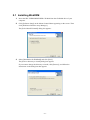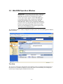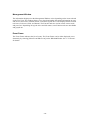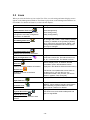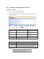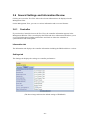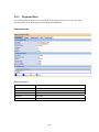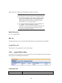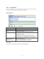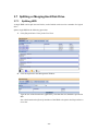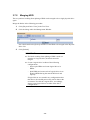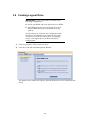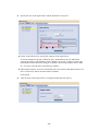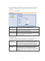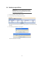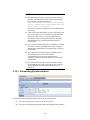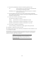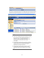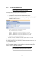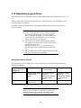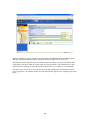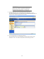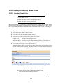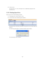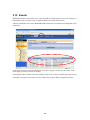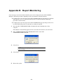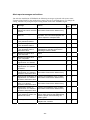
1
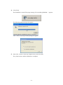
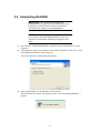
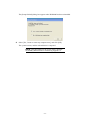
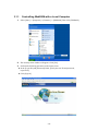
NEC Express5800 Series Web-based Promise Array Manager User's Guide (For N8103-89/N8103-101/N8103-103 Disk Array Controller) 1st Edition 11-2006 856-840000-383-A Preface This User's Guide explains the management utility [Web-based Promise Array Manager] to be used for operating N8103-89, N8103-101, or N8103-103 Disk Array Controller provided by Promise. The guide is intended for persons who are familiar with Windows functions and operation methods. For details on Windows operation, see Windows Online Help or manuals. When using Web-based Promise Array Manager, read the User's Guide provided with the system as well. Copyrights Promise® and its logo are registered trademarks of Promise Technology Inc. of the U.S.A. NEC ESMPRO and NEC EXPRESSBUILDER are registered trademarks of NEC Corporation. Microsoft, its logo, Windows, Windows Server and MS-DOS are worldwide registered trademarks of Microsoft Corporation of the U.S.A. All company names and product names mentioned herein are trademarks or registered trademarks of their respective companies. Notes: (1) No part of this manual may be reproduced in any form without the prior written permission of NEC Corporation. (2) The contents of this manual may be revised without prior notice. (3) The contents of this manual shall not be copied or altered without the prior written permission of NEC Corporation. (4) All efforts have been made to ensure the accuracy of all information in this manual. If you notice any part unclear, incorrect, or omitted in this manual, contact the sales agent where you purchased this product. (5) NEC assumes no liability arising from the use of this product, nor any liability for incidental or consequential damages arising from the use of this manual regardless of Item (4). Contents 1. Overview .................................................................................................................... 1 1.1 Web-based Promise Array Manager ..................................................................................... 1 1.2 Precautions ........................................................................................................................... 2 2. Installation.................................................................................................................. 4 2.1 Installing WebPAM .............................................................................................................. 5 2.2 Uninstalling WebPAM.......................................................................................................... 8 3. Operation.................................................................................................................. 10 3.1 Starting and Exiting WebPAM ........................................................................................... 10 3.1.1 Controlling WebPAM with a Local Computer ......................................................... 12 3.1.2 Controlling WebPAM with a Remote Computer...................................................... 13 3.1.3 Exiting WebPAM...................................................................................................... 13 3.2 WebPAM Operation Window ............................................................................................. 14 3.3 Icons ............................................................................................................................... 16 3.4 Creating or Changing User Account................................................................................... 18 3.5 Deleting User Account ....................................................................................................... 20 3.6 Several Settings and Information Review .......................................................................... 21 3.6.1 Controller ................................................................................................................. 21 3.6.2 Physical Drive View................................................................................................. 24 3.6.3 Physical Drive .......................................................................................................... 26 3.6.4 Logical Drive View .................................................................................................. 28 3.6.5 Logical Drive ........................................................................................................... 30 3.6.6 Enclosure.................................................................................................................. 32 3.6.7 Spare Drive View ..................................................................................................... 32 3.6.8 Battery ...................................................................................................................... 33 3.7 Splitting or Merging Hard Disk Drive................................................................................ 34 3.7.1 Splitting HDD .......................................................................................................... 34 3.7.2 Merging HDD .......................................................................................................... 36 3.8 Creating Logical Drive ....................................................................................................... 37 3.9 Deleting Logical Drive ....................................................................................................... 41 3.10 Synchronizing Logical Drive ............................................................................................. 42 3.10.1 Scheduling Synchronization..................................................................................... 44 3.11 Media Patrol ....................................................................................................................... 46 3.11.1 Scheduling Media Patrol .......................................................................................... 48 3.12 Rebuilding Logical Drive ................................................................................................... 49 3.13 Creating or Deleting Spare Drive ....................................................................................... 54 3.13.1 Creating Spare Drive................................................................................................ 54 3.13.2 Deleting Spare Drive................................................................................................ 55 3.14 Expanding Logical Drive ................................................................................................... 56 3.15 Events ............................................................................................................................... 58 3.16 Collecting Configuration Information ................................................................................ 59 Appendix A Preparation for Using WebPAM on Internet Explorer .......................... 60 Appendix B Report Monitoring ................................................................................... 62 Appendix C Standby/Hibernation Lock ...................................................................... 65 1. Overview 1.1 Web-based Promise Array Manager Web-based Promise Array Manager (hereafter abbreviated for WebPAM) is a Web-based application that locally or remotely manages N8103-89, N8103-101, or N8103-103 Disk Array Controller provided by Promise. WebPAM only supports Microsoft Internet Explorer (IE) 6.0 or later as its browser. After installing WebPAM, the following features become available in the system. Creating or deleting the following logical arrays on the graphical operation screen of the browser – RAID0 (data striping with one or more hard disk drives) – RAID1 (data mirroring with two hard disk drives) – RAID5 (data striping with parity with more than two hard disk drives) – RAID1 spanning (same as RAID10. Data mirroring and striping with four hard disk drives) Checking consistency among logical drives (synchronization) Checking media error in disks (media patrol) Auto-recovering degraded logical drives if entered into the state (rebuild) To manage N8103-89, N8103-101 or N8103-103 remotely from the management computer, WebPAM must be installed in the machine to which N8103-101 is connected. These two computers must be set to allow communication with each other via TCP/IP. HTTPS or SSL is used for communication via TCP/IP in order to endure security and encrypt transfer data. -1- 1.2 Precautions Be sure to read the following notes and precautions before using WebPAM: It is strongly recommended to provide media patrol or synchronization routinely for all logical drives and HDDs to be connected. Whether the media patrol or the synchronization is used may be determined as follows depending on the environment of your system. Synchronization Environment in which your system is always subject to load. --- Synchronization can continue at a constant rate under heavy system load Media patrol Environment in which your system is subject to comparatively small load in any period including the night. --- Media Patrol has lower priority than other tasks in the system, so it may make little progress under heavy system load The above action allows you to find subsequent defects (due to degradation such as aging) in files of low access frequency and unused areas as soon as possible. In rebuilding after replacement of a HDD due to a failure, subsequent defects may be found in remaining HDDs. In such a case, the system cannot be recovered. Thus, detecting subsequent defects as early as possible is extremely effective as preventive maintenance. Periodical synchronization or media patrol is effective to keep the stable operation of your system. It is strongly recommended to take the action once per week or at least once per month. For the detailed explanation and routine action, see the description on the scheduling of the synchronization or media patrol in this manual. Note that a media patrol task has been scheduled to be done on AM0:00 every Wednesday by default. To use the report monitoring by the NEC ESMPRO Manager or the express report service, the NEC ESMPRO Agent must be installed before the installation of WebPAM. To use WebPAM on Internet Explorer, some default settings of Internet Explorer must previously be changed. Change the default settings following "Appendix A Preparation for Using WebPAM on Internet Explorer." If there is no spare drive and free HDDs attached to the controller, please be sure to set Auto Rebuild Status to Disable. If Enable, you will not able to see the Port ID of the failed HDD in its event message when a logical drive goes degraded. After the installation of WebPAM, always install the Standby/Hibernation Lock following Appendix C at the end. This RAID system does not support the power control feature. To start WebPAM, more than 255 colors must be selected in the screen setup. If only up to 255 colors are selected, the popup requesting more than 255 colors appear and WebPAM cannot be started. On WebPAM, the capacity is calculated and displayed based on “1GB=1000MB, 1MB=1000bytes.” Therefore, the values displayed in the OS functions and in other applications which are based on “1GB=1024MB, 1MB=1024bytes” are different from those in WebPAM. -2- If your server is either of the followings, please be sure to read the description of “Settings tab” of “3.6.3 Physical Drive” and change the NCQ Enable option setting if required. 110Ej (EXPRESSBUILDER Ver4.140x-N) 110Gc (EXPRESSBUILDER Ver4.135x-N) x: any alphabet -3- 2. Installation IMPORTANT: Only users authorized as administrators are permitted to install and uninstall WebPAM. NOTE: You may purchase a system in which WebPAM is installed previously. For such a system, the installation procedure is not required. To install WebPAM, use the NEC EXPRESSBUILDER CD-ROM provided with your system. -4- 2.1 Installing WebPAM 1. Insert the NEC EXPRESSBUILDER CD-ROM into the CD-ROM drive of your computer. 2. Click [Software Setup] on the Master Control Menu appearing on the screen. Then click [Web-based Promise Array Manager]. The [Select Install/Uninstall] dialog box appears. 3. Select [Installation for WebPAM] and click [Next]. The [Select a directory to install] dialog box appears. If you want to change the directory to install, click [Browse], and follow the instructions in the dialog box that appears. -5- 4. Click [Next]. The installation is started. The popup message "Now installing WebPAM…" appears. The following popup message also appears. After a while, the [Setup finished] dialog box appears. 5. Select [Yes, I want to restart my computer now], and click [OK]. The system restarts, and the installation is computed. -6- IMPORTANT: To use WebPAM on Internet Explorer, some default settings of Internet Explorer must previously be changed. Change the default settings following "Appendix A Preparation for Using WebPAM on Internet Explorer." After the installation of WebPAM, always install the Standby/Hibernation Lock following Appendix C at the end. This RAID system does not support the power control feature. NOTE: To display event messages on the NEC ESMPRO Manager or to use the express report service, some settings may be required. Make the settings appropriately following Appendix B. For the event list, see Appendix B. -7- 2.2 Uninstalling WebPAM IMPORTANT: Do not uninstall WebPAM with [Adding/Removing Application] or [Adding/Removing Program] on [Control Panel]. Follow the procedure described in this chapter to uninstall WebPAM. NOTE: WebPAM is required for managing the RAID system. Do not uninstall WebPAM unless you have to uninstall for maintenance including the upgrade of the utility. 1. Insert the NEC EXPRESSBUILDER CD-ROM into the CD-ROM drive of your computer. 2. Click [Software Setup] on the Master Control Menu appearing on the screen. Then click [Web-based Promise Array Manager]. The [Select Install/Uninstall] dialog box appears. 3. Select [Uninstallation for WebPAM], and click [Next]. The uninstallation is started. The popup message "Now uninstalling WebPAM…" appears. -8- The [Setup finished] dialog box appears when WebPAM has been uninstalled. 4. Select [Yes, I want to restart my computer now], and click [OK]. The system restarts, and the uninstallation is computed. NOTE: Then depending on the system status, uninstall the Standby/Hibernation Lock following Appendix C. -9- 3. Operation This chapter describes how to start WebPAM and how to operate the screens to be displayed. 3.1 Starting and Exiting WebPAM IMPORTANT: Do not start more than one Web browser for a specific controller at a time. Whenever WebPAM is started, the security warning screen appears. Click [Yes] to display the logon screen. Even if you click "Installing certification…" to install the certification, the security warning screen appears again in the next start. The user ID and password is set to "admin" by default. In the first logon, specify "admin" as the user name and password. For changing the password "admin" to another after the logon, see "3.4 Creating or Changing User Account." Note that these user ID and password are different from those required for logging into the OS. The “Logical Drive **logical drive name** goes offline” message may be registered the first time you start the system. This is not a problem unless there are any other warning/error messages before or after the message and unless any abnormal statuses are found in the WebPAM screen. The “crypt32” error message with ID:8 may be registered in the application log at WebPAM startup. This has no effect on WebPAM operation. NOTES: Depending on the OS used, browser, and/or color scheme, the images shown in this manual may be different from the actual images. If you attempt to start WebPAM and that is the first time to start Internet Explorer with the server, a screen of internet connection preparation may be displayed. In this case, perform initial settings of Internet Explorer for the server. Whenever the system is started, the WebPAM service checks the battery status and register the result to the proper log. - 10 - If no battery is installed, a message "Battery cannot be detected" is registered. If installed, "Battery becomes normal" is registered. The battery related messages can be set so as not to be registered. For details, see “3.6.1 Controller.” - 11 - 3.1.1 Controlling WebPAM with a Local Computer 1. Select [Start] → [Programs] → [Promise] → [WebPAM]. Then click [WebPAM]. 2. The Security Alert window will appear. Click [Yes]. 3. Perform the following operation on the logon screen. In the [Login ID] and [Password] fields, specify the user ID and password, respectively. Click [Sign in]. - 12 - 3.1.2 Controlling WebPAM with a Remote Computer 1. Start the Web browser. 2. In the Address box on the browser screen, type the IP address of the Promise RAID system to be controlled and press [Enter]. For example, if the IP address is [10.10.10.10], type [https://10.10.10.10:8443/promise]. The WebPAM logon screen appears when a session with the remote system is established. NOTE: If using a proxy server for making access to the Internet, you need to bypass the proxy server. See Appendix A for the setting procedure. 3. The Security Alert window will appear. Click [Yes]. 4. On the logon screen, perform the following operations: In the [Login ID] and [Password] fields, specify the user ID and password, respectively. Click [Sign in]. 3.1.3 Exiting WebPAM Click [Logout] on the WebPAM Header of the WebPAM operation window to exit the WebPAM operation window. Click [x] at the upper right corner of the WebPAM logon window to exit it. - 13 - 3.2 WebPAM Operation Window IMPORTANT: If no polling for logical drive monitoring continues for a certain period (about an hour) with the WebPAM operation screen remaining open, popup "Please log in again" appears and the WebPAM logon screen appears again. This is based on the WebPAM security specification. If the status occurs, log into WebPAM again. When you try to display the WebPAM operation screen by using the [Return] button of Internet Explorer after logoff, also popup "Please log in again" appears and the WebPAM screen appears again. In this case, also log into WebPAM again. The WebPAM window is mainly configured with three parts; Tree View, Management Window, and Event Frame. WebPAM Header Function tab Tree View Management Window Event Frame Tree View The Tree View allows the configuration of the RAID system to be displayed hierarchically in the similar way as Windows Explorer. Each of the items in each hierarchy can be displayed extensively by displaying the subordinate hierarchies. - 14 - Management Window The information displayed on the Management Window varies depending on the items selected on the Tree View. The window allows you to check and update the setting information on users and devices and create, maintain, delete, or monitor logical drives. The displayed items include text boxes, list boxes, fields, and buttons. The Function tabs are used to control various tasks and processes. Depending on logical drives and disk status, some Function tabs are unavailable and grayed out. Event Frame The Event Frame indicates the list of events. The Event Frame can be either displayed or not alternately by selecting [Show Event/Hide Event] on the WebPAM Header. See "3.15 Events" for details. - 15 - 3.3 Icons When you click the link to an icon on the Tree View, several setting and status display screens appear on the Management Window. The features grayed out on the Management Window are unavailable. For details of features, see the relevant chapters. Tree View Management Window display Administrative Tools icon [User Management] Displays the user management, host management, and utility configuration information on WebPAM. [Host Management] User Management icon [Utility Configuration] Lists user IDs registered currently in the [Information] tab. In logon with "admin," user creation, deletion, or setting is enabled on the [Create] or [Delete] tab. In logon as a user (other than “admin”), the settings of the self password and event popup can only be changed. Displays the host IP address and display name. Host Management icon Displays the current host information. Utility Configuration icon In logon with "admin," the refresh interval of event frame can be set. The interval can be 15, 30, 60, or 300 seconds. The default is 30 sec. Host icon Displays the host information including WebPAM version, display name, IP address, and OS information. (Note: “Windows2003” will be displayed in the Windows XP 64bit environment.) Displays the host IP address information. Rescan icon Updates the screen to the latest information. The Rescan icon updates the screen status to the latest one. If you click this icon, the confirmation screen "Are you sure you want to rescan?" appears. Then click [OK]. Displays the installed RAID card. SuperTrak icon Controller icon Displays the BIOS and driver information. In addition, various settings including performance and scheduling of synchronization or media patrol can be confirmed or deleted. Physical Drive View icon / Displays the information on all connected HDDs. Use these icons to schedule media patrol and split or merge HDDs. Physical Drive icon Displays the HDD connected to each channel. - 16 - Tree View Management Window display Logical Drive View icon Displays the information on all logical drives. You can create or delete a logical drive and schedule synchronization. Displays the list of logical drives installed in this host. Logical Drive icon Displays each logical drive. Enclosure View icon Spare Drive View icon On the Management Window displayed by clicking each logical drive icon, rebuild or synchronization can be done for the logical drive. This feature is not supported. Displays the information on spare drives. Use this icon to create or delete spare. Displays spare. Displays the battery status. Battery icon Displays the battery. - 17 - 3.4 Creating or Changing User Account Creating user account To create a user account, follow the procedure below: 1. Log in WebPAM as an administrator (admin). 2. Click [User Management] in the Tree View and click the [Create] tab appearing in the Management Window. 3. Enter proper values as follows: Item name Description Available characters User ID Account used at login 4 - 20-byte alphanumeric characters Display Name User name 4 - 20-byte alphanumeric characters Password Password 4 - 8-byte alphanumeric characters Retype Password Value entered in password field Host User Rights Rights to be given to this user The host user rights are described in the table below. Right Description Creation Right of creating logical drive or spare and splitting HDD Deletion Right of deleting logical drive or spare and merging HDDs Maintenance Right of performing rebuild, synchronization, or media patrol and setting or changing controllers or physical drives Notification Right of receiving event (receiving notification by popup) NOTE: The popup report appears while the owner of the popup settings are logging into WebPAM. - 18 - 4. After completing the entry, click [Submit]. If the user account is created successfully, message "Created Successfully - Display Name (User ID)" appears. The created user is added to the list in the Information tab. Changing user account settings Select an existing user and changing the [Display Name], [Password], and [Retype Password] in the Settings tab allows the user name and password to be changed. Note that the password can be changed only by the owner. When you log into the system with an account other than administrator, only the self password and event setting may be changed. - 19 - 3.5 Deleting User Account 1. Log in WebPAM as an administrator (admin). 2. Click [User Management] in the Tree View and click the [Delete] tab appearing in the Management Window. 3. Select the user to be deleted and click [Delete]. The confirmation dialog box appears. Click [OK]. Now the user account is deleted. IMPORTANT: You cannot delete admin account. - 20 - 3.6 Several Settings and Information Review Clicking an icon on the Tree View allows the relevant information to be displayed on the Management View. On the Management View, you can see various information and set several features. 3.6.1 Controller If you select the Controller icon on the Tree View, the controller information appears in the Management Window. This screen displays the BIOS and driver information and allows you to set several information including performance and check or delete the schedules of synchronization and media patrol. Information tab The Information tab displays the controller information including the BIOS and driver versions. Settings tab The Settings tab displays the settings on controller performance. (The above image indicates the default settings of WebPAM.) - 21 - Rebuild Rate Set the priority of the rebuild process. Media Patrol Rate Set the priority of the media patrol process. Migration/Expansion Rate Set the priority of the expansion process. Attention: Migration/Expansion feature is supported only with N8103-89. Initialization Rate Set the priority of logical drive initialization. Synchronization Rate Set the priority of the synchronization. Automatic Rebuild Status Set whether the automatic rebuild is enabled or disabled. Attention: If there is no spare drive and free HDDs attached to the controller, please be sure to set Auto Rebuild Status to Disable. If Enable, you will not able to see the Port ID of the failed HDD in its event message when a logical drive goes degraded. Automatic Rebuild Policy If the automatic rebuild is enabled and a logical drive is degraded, the operation varies depending on the following settings. (The option is not displayed when Automatic Rebuild Status is set to Disabled.) Free&Spare: If the logical drive having a sufficient capacity includes unconfigured or spare disks, the rebuild is started by using the disks (the spare disks are used preferentially). Spare: The rebuild is started only when a logical drive includes spare disks. Buzzer Status Set whether buzzer beep is enabled or disabled. S.M.A.R.T. Status Set whether the S.M.A.R.T. information is acquired. S.M.A.R.T. Check Polling Interval Set the interval at which the S.M.A.R.T. information is acquired. (The option is not displayed when S.M.A.R.T. Status is set to Disabled.) Battery Not Detected Event Set whether the “battery not detected” message is registered or not at system startup. Note that the message is always registered when WebPAM detects the battery connected. Enable (default): The condition of the battery is checked and a message is logged. When the battery is not detected, the “Battery cannot be detected” message is registered. When the battery is detected and the condition is OK, the “Battery becomes normal” message is registered. Disable: No message is logged if the battery is not detected. To return to the original values at the redisplay of this screen after changing some settings, click [Reset]. To change some settings and enable the new values, click [Submit]. To return to the recommended default values, click [Default] and [Submit] in the order. Schedule tab The Schedule tab lists tasks already scheduled. - 22 - To delete a scheduled task, put a checkmark on the [Select] checkbox of the task and click [Delete]. - 23 - 3.6.2 Physical Drive View If you select the Physical Drive View icon in the Tree View, the outline of the current physical drive appears in the Management Window. On this screen, you can check the status information of the physical drive, schedule the media patrol, display or display and/or save the defective block information. In addition, splitting or merging each HDD can be done on this screen. Information tab Physical Drive Overview Drive Model Vendor ID of this HDD Port Number Port number of controller to which this HDD is connected Capacity Total capacity of this HDD (GB) Status Status of this HDD Functional The HDD operates normally. Rebuilding The HDD is now rebuilt. Synchronizing The HDD is now synchronized. Initializing The HDD is now initialized. Offline The HDD is in the set-down (failed) status. - 24 - Graphic View The Graphic View displays the information on each HDD graphically. NOTES: On WebPAM, the capacity is calculated and displayed based on “1GB=1000MB, 1MB=1000bytes.” Therefore, the values displayed in the OS functions and in other applications which are based on “1GB=1024MB, 1MB=1024bytes” are different from those in WebPAM. If you put the cursor on the bar showing device information in the Physical Drive Overview, the block information appears. The information includes the name and status of the logical drive to which the block is assigned and background tasks. Split tab See "3.7 Splitting or Merging Hard Disk Drive." Merge tab See "3.7 Splitting or Merging Hard Disk Drive." Media Patrol Schedule tab See "3.11 Media Patrol." BSL tab The BSL tab displays the bad sector list of physical drives. If an unrecoverable media error is found in a physical drive, WebPAM registers the information in the bad sector list. Clicking [Save BSL] allows the BSL information of all HDDs to be saved in a file. - 25 - 3.6.3 Physical Drive If you click the Physical Drive icon subordinate to the Physical Drive View in the Tree View, the information on the HDD appears in the Management Window. Information tab Basic Information Drive Model Vendor ID of this HDD Serial Number Serial number of this HDD Firmware Version Firmware version of this HDD Port Number Port number of controller to which this HDD is connected Target ID Not used Enclosure Not used - 26 - Drive Information Drive Status Status of this HDD Functional: The HDD operates normally. Rebuilding: The HDD is now rebuilt. Synchronizing: The HDD is now synchronized. Initializing: The HDD is now initialized. Offline: The HDD is in the set-down (failed) status. Background Activity Status of background task of this HDD Idle: No background task Patrolling: Media patrol is now executed. Patrol Paused: Media patrol is now paused. Capacity Capacity of this HDD (GB) Head Number of heads of this HDD Cylinder Number of cylinders of this HDD Ultra DMA Mode UDMA mode in which this HDD operates S.M.A.R.T. Status Status of S.M.A.R.T. of this HDD Write Cache Status Write cache status of this HDD Graphic View The Graphic View displays the information on each HDD graphically. Settings tab Write Cache Enabled Set the Write Cache mode of the HDD to Enable or Disable. The default value is “Disable.” NCQ (TCQ) Enabled (This option is displayed only when the HDD is compatible with NCQ or TCQ feature.) Set the NCQ/TCQ option to Enable or Disable. The default value is “Enable.” Attention: If your server is either of the followings, please be sure to read the description of “Settings tab” of “3.6.3 Physical Drive” and change the NCQ Enable option setting if required. 110Ej (EXPRESSBUILDER Ver4.140x-N) 110Gc (EXPRESSBUILDER Ver4.135x-N) x: any alphabet - 27 - When the mode is changed, click [Submit] to enable the change. IMPORTANT: This option is not for the disk array controller (logical drive), but for HDDs. For the Write Cache Setting for logical drives when the battery is implemented, see the description of the Write Cache setting for each logical drive in “3.6.5 Logical Drive.”. It is recommended that the Write Cache enabled is set to “Disable.” If you would like to improve performance, be sure to take preventive measures such as the use of uninterruptible power supply system (UPS) before setting to “Enable.” Media Patrol tab See "3.11 Media Patrol." BSL tab The BSL tab allows you to check the BSL (Bad Sector List) information of each HDD. Locate Drive tab This feature is not supported. Do not use the feature. 3.6.4 Logical Drive View If you select the Logical Drive View icon in the Tree View, the outline of the current logical drive appears in the Management Window. Information tab Assigned Name Name of logical drive RAID Level RAID level - 28 - Status Status of this logical drive Functional: normal, Critical: degrading, Offline: fault Background Activity Background task associated with this logical drive Idle: no background task Rebuilding: The background task is now rebuilt. Synchronizing: The background task is now synchronized. Initializing: The background task is now initialized. Capacity Capacity of this logical drive The following logical drive states appear in the Status field: Functional The logical drive operates normally. Critical Displayed when one of HDDs configuring a redundant logical drive is defected. Because the redundancy is lost, the rebuild process should be done as soon as possible. Offline Displayed when a logical drive cannot be recovered any more (a HDD in a logical drive of RAID 0 is defected or two HDDs in a logical drive of RAID 5 are defected). Delete the relevant logical drive, and replace the defected HDD(s), and create the logical drive again. Click the name of a logical drive (Assigned Name) in the Information tab to display the name of each logical drive (assigned name) in the tab. Create tab See "3.8 Creating Logical Drive." Delete tab See "3.9 Deleting Logical Drive." Synchronization Schedule tab See "3.10 Synchronizing Logical Drive." - 29 - 3.6.5 Logical Drive If you click a Logical Drive icon subordinate to the Logical Drive View in the Tree View, the information on the HDDs appears in the Management Window. Information tab Assigned Name Name of logical drive RAID Level RAID level Capacity Capacity of this logical drive Status Status of this logical drive Functional: normal, Critical: degrading, Offline: fault Background Activity Background task associated with this logical drive Idle: no background task Rebuilding (nn%): The background task is now rebuilt. Synchronizing (nn%): The background task is now synchronized. Initialization (nn%): The background task is now initialized. Background Activity State (Appearing when background task exists) Status of background task Running: The background task is now executed. Paused: The background task is now paused. Graphic View The Graphic View displays the information on each HDD graphically. - 30 - Settings tab Assigned Name Name of logical drive Write Cache Mode Selected write cache mode Write Cache Status Current write cache status The Write Cache Mode allows you to set the write cache mode of the logical drive. Write Through If this mode is selected, cache is not used in writing. Write Back If this mode is selected, cache is always used in writing. It is expected that the setting improves writing performance. However, if the battery power is insufficient, the data integrity at power-off is rather low. Thus, it cannot be recommended to use this mode. Auto Switch If an additional battery is connected and charged enough, the operation takes place in the write back mode. The improvement of the writing performance can be expected. When the battery power is insufficient, the operation takes place in the write through mode. The data integrity at power-off can be kept. If the battery state is other than Fully Charged and a voltage or temperature error occurs (the voltage is less than 3.9 VDC or the temperature is lower than 10 °C or higher than 60 °C) under the selection of "AutoSwitch," the mode is automatically changed to "Write Through." In addition, the following log is registered. AutoCache write mode of logical drive "%s" is changed to %s When the mode is changed, click [Submit] to enable the change. Drive Mapping tab Attention: This feature is supported only with N8103-89. The Drive Mapping tab indicates how HDDs are mapped to a logical drive of RAID10 if any. Expansion tab Attention: This feature is supported only with N8103-89. See "3.14 Expanding Logical Drive." - 31 - Rebuild tab See "3.12 Rebuilding Logical Drive." Synchronization tab See "3.11 Synchronizing Logical Drive." Initialization tab See "3.8 Creating Logical Drive." Activation tab The Activation tab is unavailable. 3.6.6 Enclosure This feature is not supported. 3.6.7 Spare Drive View If you click the Spare Drive View icon in the Tree View, the information on the HDD appears in the Management View. Information tab The Information tab displays the states of spare drives set now graphically. - 32 - Create tab See "3.13.1 Creating Spare Drive." Delete tab See "3.13.2 Deleting Spare Drive." 3.6.8 Battery If you select the Battery icon in the Tree View, the information on battery including its temperature, humidity, and charging status is displayed as shown in the figure below. Temperature Indicates the temperature of the battery. Note that a retry may be done when reading the temperature value, showing “Now Reading…” Voltage Indicates the voltage of the battery. Note that a retry may be done when reading the voltage value or being charged, showing shows “Now Reading…” State Indicates the battery charge state. Fully Charged: The battery is fully charged. Charging: The battery is now charged. Discharging: The battery is discharging. Recondition: The battery state is now reconditioned. Now Reading: The battery state is now being checked. Malfunction: The battery is in a malfunctioning state. If the battery state is other than Fully Charged and a voltage or temperature error occurs (the voltage is less than 3.9 VDC or the temperature is lower than 10 °C or higher than 60 °C) with the write cache mode for logical drives set to "AutoSwitch," the mode is automatically changed to "Write Through." In addition, the following log is registered. AutoCache write mode of logical drive "%s" is changed to %s - 33 - 3.7 Splitting or Merging Hard Disk Drive 3.7.1 Splitting HDD A single HDD can be split into two blocks, each of which can be used as a member of a logical drive. Split a single HDD in the following procedure: 1. Click [Physical Drive View] in the Tree View. 2. Click the Split tab in the Management Window. Type the size of the first block in [Split Size]. Note that the size should be specified in MB. Put a checkmark on the [Select] checkbox of the HDD to be split in the Physical Drive Overview. - 34 - 3. Click [Submit]. The HDD is split into two blocks. - 35 - 3.7.2 Merging HDD The two portions resulting from splitting a HDD can be merged to be a single physical drive again. Merge the blocks in the following procedure: 1. Click [Physical Drive View] in the Tree View. 2. Click the Merge tab in the Management Window. Put a checkmark on the [Select] checkbox of the HDD to be merged in the Physical Drive List. 3. Click [Submit]. IMPORTANT: If a block resulting from splitting a HDD is used as a member of a logical drive, the block cannot be merged. Create a logical drive in either of the following configurations: – Do not split HDDs and create logical drives in HDDs. – Split HDDs and create each of logical drives in an identical HDD having the same RAID level and capacity. If logical drives are created in any configuration other than above, the rebuild process may not be done at the occurrence of a fault in a logical drive. Accordingly, always create logical drives in either of the above configurations. - 36 - 3.8 Creating Logical Drive IMPORTANT: Create a logical drive in either of the following configurations: Do not split HDDs and create logical drives in HDDs. Split HDDs and create each of logical drives in an identical HDD having the same RAID level and capacity. If logical drives are created in any configuration other than above, the rebuild process cannot be done at the occurrence of a fault in a logical drive. Accordingly, always create logical drives in either of the above configurations. 1. Click [Logical Drive View] in the Tree View. 2. Click the Create tab in the Management Window. The RAID levels available now appear. Select the RAID level to be created and click [Next]. - 37 - 3. Specify the size of the logical drive and the disk drives to be used. On the Logical Drive Size, specify the capacity of the logical drive. To use the maximum capacity of the disk, put a checkmark on the Use Maximum Capacity checkbox (a checkmark is put by default). To specify a capacity, remove the checkmark from the checkbox and type a required value in Logical Drive Size in MB. Ex.: To create a logical drive of 40 GB, type "40000." Select physical drives to be used. Selectable drives are enclosed with black frames. If a drive is selected, it will be enclosed with a red frame. Click [Next]. 4. Type the name of the logical drive in Assigned Name and click [Next]. - 38 - 5. Check the logical drive name, RAID level, and logical drive capacity in the [Name], [RAID Level], and [Logical Drive Size] fields, respectively. Select other options if necessary. The options are described below. Stripe Block Size Block size of logical drive. The default is 64 KB. *Fixed to 64 KB in RAID 1. Write Cache Select any of AutoSwitch, WriteThrough, and WriteBack. See "Write cache mode" described below. Gigabyte Boundary Always set to "None." Initialization Select any of None, Quick Initialization, and Full Initialization. See "Types of initialization" described below. * Grayed out in RAID0. Write cache mode The Write Cache Mode allows you to set the write cache mode of the logical drive. For details, see the description of Write Cache Mode in “3.6.5 Logical Drive.” Auto Switch (recommended) If an additional battery is connected and charged enough, the operation takes place in the write back mode. The improvement of the writing performance can be expected. When the battery power is insufficient, the operation takes place in the write through mode. The data integrity at power-off can be expected. Write Through If this mode is selected, cache is not used in writing. Write Back If this mode is selected, cache is always used in writing. It is expected that the setting improves writing performance. However, if the battery power is insufficient, the data integrity at power-off is rather low. Thus, it cannot be recommended to use this mode. - 39 - Types of initialization 6. None (recommended) Does not perform initialization processing for the logical drive. Quick Initialization Initializes the master boot sectors only. Full Initialization Performs initialization processing for the logical drive entirely and maintain the consistency of the logical drive. After the selections, click [Finish]. The logical drive is created completely. The icon of the created logical drive is added to the Tree View. NOTE: When "Full Initialization" is selected, the initialization is started after the logical drive is created. The status of the initialization can be checked on the Initialization tab of the created logical drive. (The Initialization tab is enabled during the initialization only.) - 40 - 3.9 Deleting Logical Drive IMPORTANT: Never delete the logical drive in which the Windows file system is installed. Before deleting a logical drive, make sure that the Windows file system is not installed in the logical drive. 1. Click [Logical Drive View] in the Tree View. 2. Click the Delete tab in the Management Window. Put a checkmark on the [Select] checkbox of the logical drive to be deleted and click [Submit]. 3. The following confirmation screen appears. After the confirmation, click [OK]. - 41 - 3.10 Synchronizing Logical Drive Routine synchronization allows inconsistencies to be detected and repaired to prevent rebuilding from failing at a HDD fault. This is available for logical drives of RAID 1, 5, or 10. In order to keep the stable operation of the RAID system, it is strongly recommended to provide the routine synchronization by using the scheduling feature. Because synchronization can continue at a constant rate under heavy system load, it is recommended to use the synchronization in an environment where the HDDs are frequently accessed and the system is always subject to load. IMPORTANT: Redundancy check is not possible for all logical drives including non-initialized RAID. If you try, the following message is registered and the redundancy check is not performed. Redundancy Check was rejected because the logical drive "Logical Drive 1" has never been initialized. If the system aborts just after the start of synchronization, the progress in the following message registered to the log may not appear correctly: Synchronization on BOOT_RAID1 aborted at %d%%. Synchronization on BOOT_RAID1 paused at %d%%. To synchronize a logical drive, follow the procedure below: 1. Click the Logical Drive View icon in the Tree View. 2. Click the Synchronization Schedule tab in the Management Window. 3. Select [Fix] or [Redundancy Check] from the [Policy] pull-down menu. Fix: If an inconsistency error is detected, data is repaired from the other mating disk configuring the RAID. Redundancy Check: If an inconsistency error is detected, the process is continued without repair of the error. - 42 - 4. Click [Start Now]. The synchronization is started. The progress of synchronization appears in the Synchronization tab of each logical drive. Animation showing the synchronization is advanced appears in the Tree View. NOTE: Note that the processing rate decreases due to much load during synchronization. - 43 - NOTES: The following message is registered when you first perform synchronization to the logical drive that has been created without initialization. Synchronization is requested to perform on the logical drive "LD-name” that has never been initialized. This does not have any influences on synchronization processing. At the end of synchronization, always check the event log to see if any error occurs during synchronization. If a media error occurs, a message indicating the occurrence of the error appears before the message indicating that the synchronization has finished successfully. If a synchronization task has been scheduled, a rebuild task starts, and the scheduled time comes during the rebuild, the synchronization is skipped (not executed) for that time. If a synchronization task has been scheduled, and if the scheduled time comes while another synchronization task is being performed, the scheduled synchronization is skipped (not executed) for that time. If a synchronization task has been scheduled, and if the scheduled time comes while the power is off, the synchronization task will start after the power is turned on. 3.10.1 Scheduling Synchronization To schedule routine synchronization, follow the procedure below: 1. Click the Logical Drive View icon in the Tree View. 2. Click the Synchronization Schedule tab in the Management Window. - 44 - 3. Select [Fix] or [Redundancy Check] from the [Policy] pull-down menu. Fix: If an inconsistency error is detected, data is repaired from the other mating disk configuring the RAID. Redundancy Check: If an inconsistency error is detected, the process is continued without repair of the error. 4. Select the [Enable] radio button in the schedule setting field below [Scheduled]. If the schedule setting field does not appear, click the green triangle mark to the left of [Scheduled] to display the field. 5. Set the time at which the synchronization is started. The details of the settings are as follows: By Day Synchronization is started at the defined time everyday. By Week Synchronization is started on the defined day of every week. By Month Synchronization is started on the defined date every month. 6. If the setting is completed, click [Schedule]. After the scheduling, "Scheduled Successfully" appears at the top of the tab. The scheduling is completed in the above procedure. The scheduled synchronization can be checked by the Schedule tab of the Controller icon. See "3.6.1 Controller" for details. Synchronization is started at the defined time and repeated at the interval entered in step 3. To cancel (delete) the scheduling, click the Schedule tab of Controller, click the [Select] checkbox you want to delete, and click [Delete]. NOTE: Synchronization can be done for a specific logical drive independently. Click the Logical Drive icon in the Tree View and schedule synchronization in the Synchronization tab. - 45 - 3.11 Media Patrol The media patrol reads data in the following HDDs entirely. As HDDs can be deteriorated with age, faults in the HDDs may be detected only when they are accessed. By reading data in HDDs routinely, the media patrol enables such faults to be detected as early as possible. This enables the early appropriate action. HDDs configuring RAID HDDs set to spares IMPORTANT: The media patrol is not done for HDDs which are not configured in logical drives. Specify HDDs not configured as spare disks previously. The media patrol can detect HDD media errors as early as possible and only repair HDDs which are the members of a redundant RAID. However, the media patrol does not have the feature of checking the consistency with parity. The function starts media patrol and runs though the HDDs you specified. If you specify a task scheduling, media patrol will regularly start at the specified date and time and also run through the HDDs specified. The function does not perform endlessly. If a media error is detected in a HDD being a member of non-redundant RAID, The error sector is registered to BSL. Error during media patrol If an unrecoverable error is detected during media patrol, the error count in the Media Patrol Information is incremented. The error count indicates the accumulated value. If more than 21 errors are detected in a single media patrol, the HDD is entered into the offline status. Some access may occur during media patrol. Then the media patrol is interrupted temporarily until the access is completed. Accordingly, the media patrol can hardly cause the system performance to be decreased. Because media patrol has lower priority than other tasks in the system, it is recommended to use the media patrol in the environment where your system is subject to comparatively small load in any period including the night. For the media patrol, follow the procedure below: 1. Click the Physical Drive View icon in the Tree View. 2. Click the Media Patrol Schedule tab in the Management Window. 3. Click [Start Now]. Media Patrol starts. - 46 - The progress of media patrol appears in the Media Patrol tab of each physical drive. Animation showing that media patrol is now advanced appears in the Tree View. NOTES: At the end of media patrol, always check the event log to see if any error occurs during media patrol. If a media error occurs, a message indicating the occurrence of the error appears before the message indicating that the media patrol has finished successfully. If a media patrol task has been scheduled, and if the scheduled time comes while another media patrol task is being performed, the scheduled media patrol is skipped (not executed) for that time. If a media patrol task has been scheduled, and if the scheduled time comes while the power is off, the media patrol task will start after the power is turned on. - 47 - 3.11.1 Scheduling Media Patrol NOTE: A media patrol task has been scheduled to be done on AM0:00 every Wednesday as a default. To schedule routine media patrol, follow the procedure below: 1. Click the Physical Drive View icon in the Tree View. 2. Click the Media Patrol Schedule tab in the Management Window. 3. Select the [Enable] radio button in the schedule setting field below [Schedule]. If the schedule setting field does not appear, click the green triangle mark to the left of [Scheduled] to display the field. 4. Set the time at which the synchronization is started. The details of the settings are as follows: By Day Media Patrol is started at the defined time everyday. By Week Media Patrol is started on the defined day of every week. By Month Media Patrol is started on the defined date every month. 5. If the setting is completed, click [Schedule]. After the scheduling, "Scheduled Successfully" appears at the top of the tab. The scheduling is completed in the above procedure. The scheduled media patrol can be checked by the Schedule tab of the Controller icon. See "3.6.1 Controller" for details. Media patrol is started at the defined time and repeated at the interval entered in step 3. To cancel (delete) the scheduling, click the Schedule tab of Controller, click the [Select] checkbox you want to delete, and click [Delete]. NOTE: Media patrol can be done for a specific physical drive independently. Click the Physical Drive icon in the Tree View and schedule media patrol in the Media Patrol tab. - 48 - 3.12 Rebuilding Logical Drive The rebuild can recover redundancy when a single HDD is defected in the RAID level of 1, 10, or 5. During rebuild, data read and write operations are enabled. However, the redundancy is lost until the rebuild is completed. If a HDD is defected, the logical drive including the HDD is entered into the critical state, which is notified. IMPORTANT: If there is no spare drive and free HDDs attached to the controller, please be sure to set Auto Rebuild Status to Disable. If Enable, you will not able to see the Port ID of the failed HDD in its event message when a logical drive goes degraded. The progress percentage in the following message may change to incorrect value when you click Pause while the pregress is 0%. Rebuild on logical drive “%s” paused at %d%%. This message is also registered in the system event log. During rebuild, the system is subject to much load and thus the processing rate is decreased. Automatic start of rebuild The rebuild process for a logical drive in the critical state is automatically started under the following conditions: [Automatic Rebuild Policy] in Controller – Settings tab Existing spare disk New disk substituting for defected disk Spare Using this disk, rebuild Not used for rebuild. is automatically Rebuild is automatically started if started. this disk is set to spare. Not used for rebuild. Rebuild is automatically started if this disk is set to spare. Free&Spare Used for rebuild at the highest priority. Used for rebuild (*1). Used for rebuild (*1). (*1: Used in the ascending order of port numbers.) IMPORTANT: Please make sure that Auto Rebuild Status is set to “Enable” in Controller- Settings tab to enable automatic start of rebuild. For details, see the description of the Settings tab in “3.6.1 Controller.” - 49 - Existing unconfigured disk During rebuild, the progress appears in the Information and Rebuild tabs of the Management Window. Animation showing that the rebuild is advanced appears in the Tree View. Rebuild fails if more than 20 errors are found in read source disks. As proper rebuild has been impossible at that time, build the system again by using new disks. (The rebuild may be done again from the beginning by using the Restart button. However, it cannot be recommended.) If a fault occurs in a block of a logical drive having split configuration and rebuild is started with a spare drive, the rebuild will also be started for another logical drive configuring the other block. - 50 - At the completion of the rebuild, the logical drive returns to the normal state. NOTES: At the end of rebuild, always check the event log to see if any error occurs during rebuild. When a media error occurs, a message indicating the occurrence of the error appears before the message indicating that the rebuild has terminated normally. The interval from the removal of the defected HDD to the installation of a substitute HDD should be 90 sec or longer. If the Buzzer Status is set to “Enable” in the controller setup, the buzzer beeps with the logical drive being in the critical or offline status or during rebuild. To switch the buzzer on/off, use the Buzzer Status radio button in the Settings tab of the controller. The buzzer sound stops when the logical drive becomes Functional. The buzzer sound may not stop depending on the type of your system. In this case, set the option to Disable and restart the system to stop the buzzer sound. The buzzer feature cannot be used if the sound module is not installed. Manual start of rebuild The rebuild process for a logical drive in the critical state can be manually started. - 51 - IMPORTANT: Please make sure that Auto Rebuild Status is set to “Disable” in Controller- Settings tab to enable automatic start of rebuild. For details, see the description of the Settings tab in “3.6.1 Controller.” 1. Click the Logical Drive icon in the critical state in the Tree View. The status of the logical drive will be displayed in the Management Window. The following image shows that a RAID1 has become degraded due to the failure on the disk on Port 4 and been replaced with a new disk.) 2. Click the Rebuild tab on the Management Window. The portion that you can use for rebuilding are enclosed with red frames, being displayed as “Free.” You cannot use the portion enclosed with gray frames. - 52 - 3. Click the portion that you will use for rebuilding on the Management Window. The selected portion is enclosed with a red frame. 4. Click [Start Now] to start rebuilding. - 53 - 3.13 Creating or Deleting Spare Drive 3.13.1 Creating Spare Drive IMPORTANT: Do not use the following hard disk drives to create spare drives: Hard disk drives already used by logical drives Hard disk drives already partitioned When a hard disk drive is defected in a redundant logical drive, a spare drive is used to protect the logical drive. In actual, if a hard disk drive is defected in a redundant logical drive, a spare drive is provided with rebuild to substitute for the defected hard disk drive for protecting the logical drive. Create a spare drive in the procedure below: 1. Click [Spare Drive View] in the Tree View. 2. Click the Create tab in the Management Window. 3. Select the type of the spare drive from [Spare Drive Type]. 4. Global Spare: Available for any logical drive. Dedicated Spare: Available only for the specified logical drive. (The name of a logical drive already existing appears.) Select a physical drive to be set to the spare drive. Available physical drives are enclosed with black frames. The selected physical drive will be enclosed with a red frame. The physical drives enclosed with blue frames are already the members of the logical drive. IMPORTANT: Set unconfigured disks as spare disks previously. Set the capacity of the dedicated spare disk to be the same as that of the relevant logical drive. - 54 - 5. Click [Create]. The spare drive is set. The created spare drive is additionally displayed in the Information tab. 3.13.2 Deleting Spare Drive Delete a spare drive in the following procedure: 1. Click [Spare Drive View] in the Tree View. 2. Click the Delete tab in the Management Window. Put a checkmark in the [Select] checkbox of the spare drive to be deleted and click [Delete]. The following popup appears. Confirm the deletion and click [OK]. The selected spare drive is deleted. - 55 - 3.14 Expanding Logical Drive IMPORTANT: This feature is supported only with N8103-89. Before expanding a logical drive, always back up the data in the disks. If an unexpected error occurs during expansion, some data may be broken in the disks. Expansions in RAID5 and RAID0 are enabled. In expansion, the capacity of the expanded drive should be the same as that of the original drive. Before expansion for a logical drive of split configuration, the disk to be added should be split with the same capacity. If not, either split block of the logical drive can be expanded but the other split block cannot be expanded. 1. Click the Logical Drive View icon in the Tree View. 2. Click the Logical Drive icon to be expanded. 3. Click the Expansion tab in the Management Window. - 56 - 4. Select the physical drive to be used for expansion. The available physical drives are enclosed with black frames. The selected physical drive is enclosed with a red frame. 5. Click the [Start Now] button. The expansion is started. The progress of expansion appears in the Expansion tab of the logical drive. Animation showing the expansion is advanced appears in the Tree View. - 57 - 3.15 Events WebPAM classifies and records every event occurred in a RAID system as an error, warning, or information. This is valid to solve or diagnose failures occurred in the system. "Show Event/Hide Event" of the WebPAM header allows the event frame to be displayed or not alternately. At first, up to 20 new events are displayed. Click [Prev Page] to see the next 20 events. Click [Next Page] to see the previous 20 events. Click [Show Filter] to filter events by using the event level (severity) and the date range as keys. Click [Save Log] to record events in a file. Click [Clear Log] to delete all registered events. - 58 - 3.16 Collecting Configuration Information You can acquire the information regarding controller and array configuration information. This feature is only for maintenance. Please use the feature only when you are requested to use it by a field engineer. 1. Click [Configuration] in the WebPAM Header field. The configuration information will be displayed in the Management Window. 2. Scroll the list displayed and click [Save] at the bottom of the window to save the configuration information. - 59 - Appendix A Preparation for Using WebPAM on Internet Explorer Microsoft Internet Explorer (IE) 6.0 or later is only supported as the browser operating WebPAM. Setting Security Level When Internet Explorer uses security set at a high level, some troubles may occur. Security of a high level disables Java scripts. When your web browser uses security of a high level, the following settings must be enabled. - JavaScript Set security in the custom level as follows: 1. Click [Tools] → [Internet Options] of Internet Explorer to display the [Internet Options] dialog box. 2. Click the [Security] tab. 3. Select [Internet] and click [Custom Level]. The [Security Setting] dialog box appears. 4. Enable the following setting: – Active script - 60 - Setting proxy server Bypass the proxy server as follows if used: 1. Click [Tools] → [Internet Options] of Internet Explorer to display the [Internet Options] dialog box. 2. Click the [Connections] tab and [LAN Setting]. The [Local Area Network (LAN) Setting] dialog box appears. Set the following depending on the state of the [Use a proxy server for your LAN] checkbox. If a checkmark is not put in the checkbox, click [OK] to terminate the process. If a checkmark is put in the checkbox, put a checkmark in [Bypass proxy server for local addresses] and click [Advanced]. Then type the IP address of the managed RAID system in the entry of the [Exceptions] area. Making animation showing advance of synchronization or rebuild displayed 1. Click [Tools] → [Internet Options] of Internet Explorer. 2. Select the [Advanced] tab and make sure that a checkmark is put on [Play animations in web pages] in the [Multimedia] section. 3. If not, put a checkmark. To be ready for saving ASMBE event log files 1. Select “Internet Options” from the Tools menu of Internet Explorer. 2. Select the [Security] tab and click [Custom Level]. 3. Enable the following setting: Downloads section - File download - 61 - Appendix B Report Monitoring Event messages associated with this RAID system can be displayed on the NEC ESMPRO Manager. Select the procedure depending on the environment as described below. 1. To display the event messages on the NEC ESMPRO Manager operating on a machine other than the server to which the RAID system is connected, take the following procedure on the machine. To display the event messages on the NEC ESMPRO Manager operating on the server to which the RAID system is connected, no setting is required. Insert the NEC EXPRESSBUILDER CD-ROM into the CD-ROM drive of the computer. If the Master Control Menu appears on the screen after the insertion, close the menu. 2. Start "\WEBPAM\WPMALERT\WPMMANEN.EXE" in the NEC EXPRESSBUILDER CD-ROM. 3. Click [Yes]. NOTE: If you click [No], the operation terminates without setting. 4. Click [OK]. 5. Reboot the system. - 62 - Alert report messages and actions Just after the installation of WebPAM, the following messages registered with source name "Promise Napa I2API" in the application event log are set as reported sources. To change the setting, redefine it by using the report setting feature of the NEC ESMPRO Agent. Manager ALIVE Check if some defects occur in HDDs and cables. Remove the defects if any. √ √ %d disk error logged on disk %d Bad sectors have been accumulated in the HDD. The user should prepare the HD for replace or hotspare HDD. √ √ 523 Rebuild on logical drive "%s" paused at %d%% None √ - 524 Rebuild on logical drive "%s" aborted at %d%% None √ - 525 Rebuild on logical drive "%s" aborted at %d%% because of error Rebuild failed. After checking the WebPAM log, take the proper action following the User's Guide. √ √ 526 Rebuild on logical drive "%s" resumed None √ - 527 Rebuild on logical drive "%s" completed None √ - 528 Foreground Initialization on logical drive "%s" started None √ - 529 Foreground Initialization on logical drive "%s" paused at %d%% None √ - 531 Foreground Initialization on logical drive "%s" aborted at %d%% because of error Check if some defects occur in HDDs and cables. Remove the defects if any. √ √ 537 Background Initialization on logical drive "%s" aborted at %d%% because of error Check if some defects occur in HDDs and cables. Remove the defects if any. √ √ 543 Synchronization on logical drive "%s" aborted at %d%% because of error Check if some defects occur in HDDs and cables. Remove the defects if any. √ √ 549 Redundancy Check on logical drive "%s" aborted at %d%% because of error Check if some defects occur in HDDs and cables. Remove the defects if any. √ √ 567 Rebuild on logical drive "%s" rebuild on stream %d aborted at %d%% Rebuild failed due to the target HDD failure. After checking the WebPAM log, take the proper action following the User's guide. √ √ 1283 Memory multi bit error Failure detected in the controller. Replace the controller. √ √ Event ID Message Action 271 Media patrol on disk %d aborted at %d%% because of error 275 - 63 - The above table shows the event IDs in decimal. The events listed in the table are reported to NEC ESMPRO Manager. The symbols such as %1 in messages are padding characters. - 64 - Appendix C Standby/Hibernation Lock Installing Standby/Hibernation Lock disables the system to be entered into the standby or hibernation state. In any environment using N8103-101/N8103-103 RAID system, the Standby/Hibernation Lock feature is not supported. Be sure to install the Standby/Hibernation Lock in the following procedure. Before the Standby/Hibernation Lock can be uninstalled, whether the driver is used by another software must always be checked. Installation Install the Standby/Hibernation Lock in the following procedure. 1. Log on the system with an account having the administrator authority (such as administrator). 2. Before starting the installation, exit from all applications being executed. 3. For the Windows x64 Editions (64-bit OS) environment, start "\WEBPAM\ACPIDV64\EXPLOCK.BAT" in the attached CD-ROM. For other Windows environments, start "\WEBPAM\ACPIDV32\PAM_INST.BAT" in the attached CD-ROM. A dialog box indicating no driver signature may appear on the way as shown below. Select [Yes] if it appears. The following message appears on the command prompt. Driver Installed successfully. Now the installation is completed. - 65 - Uninstallation NOTE: Some other software products require the system prevented from entering into the standby or hibernation state. Before uninstalling Standby/Hibernation Lock, refer to the user's guides of the installed software products to check whether they require Standby/Hibernation Lock. The following software products may possibly require Standby/Hibernation Lock: Power Console Plus Adaptec Storage Manager Uninstall the Standby/Hibernation Lock in the following procedure: 1. Log on the system with an account having the administrator authority (such as administrator). 2. Select [Settings] from the Start menu and click [Control Panel]. 3. Select [Computer Management] in [Administrative Tools] and click [Device Manager]. The device list appears. 4. In the device list, double-click [System Device] and [Standby/Hibernation Lock] in the order. The [Standby/Hibernation Lock Properties] dialog box appears. 5. Click the Driver tab. Then clock [Delete]. The [Confirm Device Removal] dialog box appears as shown below. 6. Click [OK]. Now the uninstallation is completed. - 66 - Confirmation of Setup The following procedure can check whether Standby/Hibernation Lock is installed or not. After installing or uninstalling Standby/Hibernation Lock, follow the procedure to check the result of the installation or uninstallation. 1. Start [Computer Management] in [Administrative Tools] and click [Device Manager]. 2. See the device list to make sure that [Standby/Hibernation Lock] appears in [System Device]. In uninstallation, make sure that [Standby/Hibernation Lock] does not appear in [System Device]. - 67 - Screen Display Appearing when Standby/Hibernation Lock Prevents System from Entering into Standby or Hibernation State Installing Standby/Hibernation Lock in a system disables the system to be entered into the standby or hibernation state. For example, if you select the hibernation state from the shutdown menu, the popup appears to stop the system entering into the hibernation state. The popup does not mean the occurrence of an error in Standby/Hibernation Lock. Instead it indicates that Standby/Hibernation Lock normally prevents the system from entering into the standby or hibernation state. The popup cannot be suppressed because it is displayed by the operating system. Click [OK] to terminate the popup. If it is determined that the system is prevented from entering into the standby or hibernation state, the following log is stored in the event log: The log is stored by the operating system in the event log. The message "The system sleep operation failed" appears in the Description field in spite of whether an attempt is made to enter the system into the standby or hibernation state. - 68 -