1
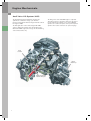
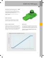
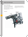
Service Training
The 2.0L 4V TFSI Engine with AVS
Self-Study Program 922903
Audi of America, LLC
Service Training
Printed in U.S.A.
Printed 7/2009
Course Number 922903
©2009 Audi of America, LLC
All rights reserved. Information contained in this manual is
based on the latest information available at the time of printing
and is subject to the copyright and other intellectual property
rights of Audi of America, LLC., its affiliated companies and its
licensors. All rights are reserved to make changes at any time
without notice. No part of this document may be reproduced,
stored in a retrieval system, or transmitted in any form or by
any means, electronic, mechanical, photocopying, recording or
otherwise, nor may these materials be modified or reposted to
other sites without the prior expressed written permission of
the publisher.
All requests for permission to copy and redistribute
information should be referred to Audi of America, LLC.
Always check Technical Bulletins and the Audi Worldwide
Repair Information System for information that may supersede
any information included in this booklet.
Table of Contents
Introduction. . . . . . . . . . . . . . . . . . . . . . . . . . . . . . . . . . . . . . . 1
Engine Mechanicals . . . . . . . . . . . . . . . . . . . . . . . . . . . . . . . . 4
Oil Circulation System. . . . . . . . . . . . . . . . . . . . . . . . . . . . . 14
SULEV 2.0L TFSI Engine . . . . . . . . . . . . . . . . . . . . . . . . . . . . 26
Service. . . . . . . . . . . . . . . . . . . . . . . . . . . . . . . . . . . . . . . . . . . 45
EA 888 Engine Development . . . . . . . . . . . . . . . . . . . . . . . 46
Knowledge Assessment . . . . . . . . . . . . . . . . . . . . . . . . . . . 51
The Self-Study Program provides introductory information regarding the design
and function of new models, automotive components or technologies.
Reference
Note
The Self-Study Program is not a Repair Manual!
All values given are intended as a guideline only and refer
to the software version valid at the time of publication of the SSP.
For maintenance and repair work, always refer to the current technical literature.
i
Notes
ii
Introduction
The turbocharged 2.0L 4V chain-driven AVS engine (CAEB)
described in this Self-Study Program is a development of
the 1.8L chain-driven engine (EA 888 family) introduced
in Europe in 2006. The 1.8L engine, known as the Stage 0
engine, was the basis for the chain-driven 2.0L 4 cylinder
engine (CCTA/CBFA) introduced in North America during
the 2008 model year.
This EA 888 family of engines is replacing the belt-driven
camshaft engines within the Volkswagen Group world
wide.
The 2.0L 4V chain-driven AVS engine is a further
development of the earlier CCTA/CBFA engine. The
cylinder block, crankshaft assembly and pistons of the
CCTA/CFBA engine are similar to those of the CAEB
engine. However, major changes to the cylinder head and
the addition of the Audi Valve Lift System (AVS) to the
exhaust camshaft of the CAEB distinguishes this engine
from the CCTA/CBFA engines.
Also included in this Self-Study Program is a description
of changes needed to make a non-AVS 2.0L 4V chaindriven engine compliant with SULEV emission standards.
To see a brief description of the development history and
a specification comparison of the EA 888 engines, please
see the Appendix at the end of this book.
1
Introduction
Technical Description
Four Cylinder, Four Valve, FSI
Turbocharged Gasoline Engine
Engine Block
Engine Management
– Cast Iron Crankcase
– MED 17 Engine Control
– Balancer Shafts in Crankcase
– Hot-Film Air Mass Flow with Integral Temperature
Sensor
– Forged Steel Crankshaft
– Self-Regulating Sump-Mounted Oil Pump —
Chain-Driven by Crankshaft
– Timing Gear Chain — Front End of Engine
– Balancer — Chain-Driven at Front End of Engine
Cylinder Head
– 4-Valve Cylinder Head
– 1 INA Intake Camshaft Adjuster
– Audi Valve Lift System (AVS) on exhaust camshaft only
Intake Manifold
– Tumble Flap
Fuel Supply
– Demand Controlled on Low and High-pressure Ends
– Multi-Port High-Pressure Injector
2
– Throttle Valve with Contactless Sensor
– Map-Controlled Ignition with Cylinder-Selective,
Digital Knock Control
– Single-Spark Ignition Coils
Turbocharging
– Integral Exhaust Turbocharger
– Charge-Air Cooler
– Boost Pressure Control with Overpressure
– Electrical Wastegate Valve
Exhaust
– Single-Chamber Exhaust System with Close-Coupled
Pre-Catalyst
Combustion Process
– Fuel Straight Injection
Introduction
Torque/Power Curve
201 (150)
265 (360)
Power in hp (kW)
Torque in lb ft (Nm)
243 (330)
220 (300)
161 (120)
200 (270)
177 (240)
121 (90)
155 (210)
133 (180)
80 (60)
110 (150)
88 (120)
67 (90)
40 (30)
44 (60)
22 (30)
0
0
0
1000
2000
3000
4000
5000
6000
7000
Engine Speed in RPM
Specifications
Engine Code
Type of Engine
Displacement
CAEB
Turbocharged Inline 4-Cylinder FSI Engine
121 cu in (1984 cm3)
Maximum Power
200 hp (147 kW) @ 5100 – 6000 rpm
Maximum Torque
206 lb ft (280 Nm) @ 1700 – 5000 rpm
Number of Valves Per Cylinder
4
Bore
3.2 in (82.5 mm)
Stroke
3.7 in (92.8 mm)
Compression Ratio
Firing Order
Engine Weight
Engine Management
Fuel Grade
Exhaust Emission Standard
9.6 : 1
1-3-4-2
317 lb (144 kg)
Bosch MED 17.5
95/91 RON
ULEV II / SULEV for various states
3
Engine Mechanicals
Audi Valve Lift System (AVS)
The Audi Valve Lift System (AVS) was developed to
optimize the combustion charge cycle. AVS was
introduced in the North American Region with the 3.2L V6
FSI engine in 2008.
The AVS application on the turbocharged 2.0L CAEB
engine is different from that of the 3.2L V6 AVS engine.
On the 2.0L CAEB engine, AVS changes the lift and timing
of the exhaust valves only.
The firing order of the 2.0L CAEB engine is separated.
This “firing sequence separation” means the gas pulses
produced during the exhaust cycles of the individual
cylinders do not effect the pulses of the previously fired
cylinders. The result is referred to as “pulse charging.”
Intake
Camshaft
Exhaust
Turbocharger
Exhaust Camshaft with
Audi Valve Lift System
4
Engine Mechanicals
The mechanical design and function of AVS on the
4-cylinder TFSI engine closely resembles the 6-cylinder
naturally aspirated engine. However, different
thermodynamic effects are used.
At low engine speeds, a narrow profile cam lobe contour
is used. At high engine speeds the AVS changes to a
wider profile cam lobe contour.
The narrow cam lobe contour provides very late exhaust
valve opening. This effectively prevents back-flow of
exhaust gas during the valve overlap phase due to the
pre-exhaust pulse (at the exhaust valve opening point)
of the cylinder, which is offset at 180° crankshaft angle.
Advanced intake valve timings are therefore possible.
Design of the Exhaust Camshaft
The positive cylinder pressure gradient allows the
combustion chamber to be effectively purged. This
enhances fuel mixture by reducing the residual gas
content in the cylinder, and by facilitating advanced
intake valve timings (because less intake air is expelled
after BDC).
These improvements also result in much better response
and much higher torque at low rpm. Charge pressure can
be built up more quickly, making the torque curve steeper
and minimizing turbo lag.
Cam Elements with
Internal Splines
Exhaust camshaft
with external splines
5
Engine Mechanicals
Modifications to the Roller Cam
Followers
The roller cam followers for the exhaust camshaft have
been designed to reach both valve lift lobes on the cam
elements. To achieve this, the roller is now larger in
diameter and narrower in width.
At the same time, the roller cam followers have been
optimized for low friction by using improved bearings. To
prevent the roller cam followers from tilting downward,
they are permanently connected to the support element.
For this reason, a roller cam follower can only be replaced
with a complete, pre-assembled module.
Exhaust Side with Audi
Valve Lift System
Intake Side
Roller with
Larger Diameter
Non-Detachable
Connection to
Support Element
Low Friction
Bearing
6
Engine Mechanicals
Function
Each cylinder has its own movable cam element mounted
on the exhaust camshaft. Two valve lift contours are
possible for each exhaust valve. Changing-over between
the large and small cam lobe contours is achieved by the
longitudinal displacement of the cam elements.
The cam elements are moved on the exhaust camshaft
by solenoid actuators. While one actuator switches
from small valve lift to large valve lift, the other actuator
switches from large valve lift to small valve lift.
The second actuator switches back from large valve lift
to small valve lift. When an actuator is activated by the
Engine Control Module (ECM), a metal pin is extended
and engages in the displacement groove of the cam
element.
The cam element is designed to move automatically
when the camshaft rotates, thereby changing over both
exhaust valves to the other cam lobe contour.
However, the displacement groove in the cam elements
must be shaped so that the metal actuator pin is pushed
back again after the changeover is made. The metal pin
cannot be actively changed back by the ECM.
Actuators with
Metal Pin
Ladder
Frame
Axial
Bearing
Exhaust
Camshaft
Locking of the Cam Elements
Displacement
Groove
Cam
Element
To ensure that the cam elements are not displaced too
far when they are adjusted, adjustment travel is limited
by a stop. The stops are camshaft bearings in the cylinder
head cover.
The cam elements are located and held in place by a
detent in the camshaft with spring-loaded balls.
Spring-Loaded
Ball
Cam
Element
Displacement
Groove
7
Engine Mechanicals
Cam Lobe Contour
There are two cam lobe contours per valve on each cam
element.
The small cam lobes (shown in green) implement a
valve opening stroke of 0.25 in (6.35 mm). The length
of opening is 180° crankshaft angle. The exhaust valve
closes 2° after TDC.
The full stroke provided by the large cam lobes (shown in
red) is 0.40 in (10 mm) with a length of opening of 215°
crankshaft angle. The exhaust valve closes 8° before TDC.
Method of Operation
Small Cam Lobes
(low engine speeds)
8
Large Cam Lobes
(high engine speeds)
Engine Mechanicals
Camshaft Adjustment Actuators F366 – F373
The camshaft adjustment actuators are electromagnetic
solenoid-type actuators. Two actuators are used per
cylinder. One actuator moves the cam element on the
camshaft for large valve lift. The other actuator resets the
cam element for small valve lift.
Each actuator is attached externally to the cylinder head
cover by a bolt. They are sealed with O rings. When the
actuator is activated by the ECM, a metal pin engages the
displacement groove in the cam element, thereby moving
the other cam lobe into position.
Design
Electrical
Connection
Magnetic
Coil
Mounting
Lug
Permanent
Magnet
O-Ring
Damper
Ring
Solenoid
Core
Pole
Plate
Metal
Pin
O-Ring
Guide
Tube
9
Engine Mechanicals
Function
A solenoid is integrated in the actuator. When the
solenoid is activated by the ECM, a metal pin is extended.
The solenoid is activated through brief application of
battery voltage.
When the metal pin is extended, it is held in position by a
permanent magnet on the actuator housing.
Due to the quick extension time (18 – 22 ms), the metal
pin undergoes very rapid acceleration. A damping ring
near the permanent magnet ensures that the pin does
not bounce back or become damaged.
The metal pin extending into the displacement groove
then moves the cam element as the camshaft rotates.
Not Activated
The contour of the displacement groove is designed to
push the metal pin of the actuator back after just under
one revolution of the actuator. The permanent magnet
ensures that the metal pin remains in this position. When
the permanent magnet pushes the metal pin, voltage is
induced in the magnetic coil of the solenoid.
This return signal is registered by the ECM. It can only
be generated if the metal pin is pushed by back by
the displacement groove after the cam element has
been moved. The ECM evaluates the signal input as a
successful adjustment.
Electrical
Connection
Activated
Magnetic Coil
Solenoid Coil
Pole Plate
Permanent
Magnet
Damper Ring
Metal Pin
10
Engine Mechanicals
Activation of the Cam
Adjustment Actuators
The Camshaft Adjustment Actuators are activated by
the ECM, which provides a ground signal. Voltage to
the actuators is supplied by Motronic Engine Control
Module Power Supply Relay J271. The system is ready for
operation above a coolant temperature of 14°F (–10°C).
When the engine is started, the larger contour lobes are
in position. Immediately after engine start, the system
changes over to the smaller contour lobes.
When the engine stops, the AVS switches back to the
large contour cam.
The maximum power input per actuator is 3 amperes.
Legend
F366 – F373 Cam Adjustment Actuators
J271
Motronic Engine Control Module Power Supply Relay
J623
Engine Control Module (ECM)
Activation of a Cam Adjustment Actuator
Battery Voltage [Ubat]
End of Actuator Activation
Return Signal on Correct Configuration
Actuator Activation
Adjustment Travel
11
Engine Mechanicals
Changing Over Between
Working Ranges
The illustration below shows in schematic form the
working range of the AVS when the engine is at operating
temperature.
In the engine speed range required for change-over to
large valve lift, the intake manifold flaps are also opened
wide.
It can be seen that the small valve lift is used up to
medium engine speeds of approximately 3100 rpm.
Audi Valve Lift System (AVS) in the Operating Ranges
266 (360)
Torque M in lb ft (Nm)
221 (300)
177 (240)
133 (180)
86 (120)
44 (60)
1000
2000
3000
4000
5000
Engine Speed in [rpm]
1
Small Valve Lift
2
Operating Point (at approximately 3100 rpm)
Note
This illustration shows an example of
a torque curve and AVS operating point.
Both are dependent on the current ECM
software version, and can change in the
course of ongoing model development.
12
3
Large Valve lLift
6000
7000
Engine Mechanicals
Self-Diagnostics
How the System Responds to Faults
The engine self-diagnostics check the mechanical
function of the cam adjustment actuators (changeover to
the other cam lobe contour) and the system’s electrical
connections.
If one or more actuators fails, the ECM will initially
attempt (several times) to change over to the other cam.
If no adjustment is made, the cam elements that cannot
be adjusted remain in position.
A system test is performed after the engine is started.
The ECM activates each actuator for this purpose.
All other cam elements are changed over to the large
cam. They then remain in this position while the engine
is running. The next time the engine is started, another
attempt is made to adjust all cam elements.
Both configurations are tested and evaluated. This
system test is audible and is performed whenever
the engine is started. System failure will result in
corresponding DTC entries.
Depending on the nature of the fault, the driver may
notice a slight variation in engine idling speed or a
different engine response under acceleration.
Vehicle self-diagnostics
004.01 - Interrogate fault memory
1 Fault detected
SAE code
P11A100
Text
Cam adjuster “A”, cylinder 1
Electrical fault/open circuit
Activation of the Warning Lamps
Exhaust emissions do not deteriorate due to system
failure and because virtually no adverse handling
effects may result, neither Electronic Power Control
Warning Lamp K132 nor Malfunction Indicator Lamp K83
is activated. However, corresponding DTC entries are
generated.
01 - Engine electronics
EV_ECM20AVS_X1
Status
active/
static
Ambient
conditions
13
Oil Circulation System
Positive Crankcase Ventilation
The following components were modified to achieve this
goal:
One of the goals in designing this new engine was
to provide greater driver, passenger, and pedestrian
safety in the event of a collision. For instance, the more
compact design of the components above the cylinder
head cover provides more clearance between the engine
and hood. This translates to a larger crumple zone for the
dissipation of energy upon impact.
– Blow-by gas duct integrated in the cylinder crankcase
– Fine oil separator module with integrated pressure
regulating valve, non-return valve and positive
crankcase ventilation valve (PCV valve)
Valve Unit
Blow-By Line to Intake Manifold
(naturally aspirated mode)
Blow-By Line to Exhaust
Turbocharger (charging mode)
Non-Return
Valves
Pressure
Regulating
Valve
PCV
Combination
Valve
Diagnostic
Channel
Cyclone
Blow-By Duct in
Cylinder Head and
Cylinder Block
14
Oil
Return
Line
Oil Circulation System
Overview
Breather
Module
Blow-By Inlet into
the Intake Manifold
(naturally aspirated
mode)
Blow-By Inlet into the
Exhaust Turbocharger
(charging mode)
Blow-By Duct in
Cylinder Head and
in Cylinder Block
Oil Return Duct
in Cylinder Head,
Cylinder Block
and Oil Pan
Oil
Return
Line
Blow-By Gases
from the
Cylinder Block
Non-Return
Valve
Oil Return
Line Below
the Dynamic
Oil Level
Reference
The components are positioned differently,
but have retained the same functions as
on the 1.8L TFSI engine (base engine).
For further information, refer to Self-Study
Program 921703: Audi 2.0 Liter ChainDriven TFSI Engine.
15
Oil Circulation System
Overview
The oil circulation system of the 2.0L TFSI CAEB engine is
unchanged from the CCTA/CBFA engine.
The biggest difference between the two engines is
the use of a new self-regulating oil pump on the CAEB
engine.
Oil Pressure
Regulation
Valve N428
Self-Regulating
Oil Pump
16
Oil Circulation System
Self-Regulating Oil Pump
Oil Pressure
Regulation
Valve N428
A newly developed self-regulating engine oil pump is
used on the 2.0L TFSI CAEB engine. The main purpose
of this development is to increase pump operating
efficiency and in turn, reduce fuel consumption.
When compared to other self-regulating oil pumps, this
design has a more efficient control concept.
Drive
Pump
Gear
Design
Pumped Oil
With an external gear pump, the driven pump gear is
axially displaceable in relation to the drive gear. This
means that the driven gear can move and change the
amount the gear lobes mesh with those of the drive gear
under certain operating conditions.
By displacing the driven pump gear, the delivery rate and
pressure in the oil circulation system can be regulated in
a controlled manner.
Driven Pump
Gear (axially
displaceable)
Intake from
the Oil Pan
Overview of the Components
Pump
Housing
Input Shaft with
Drive Pump Gear
Compression
Spring of the
Cam Lobe Unit
Control
Piston
Cam
Lobe
Unit
Regulating
Spring
Driven Pump
Gear (axially
displaceable)
Cold
Start
Valve
Check
Valve
Final Drive
Sprocket
Cover
17
Oil Circulation System
Function
Conventional Method of Control
With a conventional oil pump, the delivery rate increases
as the engine RPM increases. The oil consumers in the
engine cannot process the excess oil being delivered, so
the oil pressure increases.
This is achieved by axial displacement of the cam lobe
unit or in other words, by displacement of the oil pump
gears relative to one another. The delivery rate is highest
when both pump gears are aligned exactly opposite
each other. The greater the axial displacement of the
driven pump gear, the lower its delivery rate will be (only
oil displaced between the pump gears is conveyed).
The pump gear is displaced by the incoming filtered
oil pressure acting on the front piston face of the cam
lobe unit. A compression spring also acts upon the front
piston face of the cam lobe unit.
Previously, pressure limiting took place inside the
pump. A mechanical valve opened for this purpose.
However, since the pump was still operating at its
maximum delivery rate, a portion of the input energy was
inefficiently converted to heat.
The concept of the new control system involves
two different pressures. The low pressure setting is
approximately 26 psi (1.8 bar). The system changes to the
high pressure setting, approximately 48 psi (3.3 bar), at
an engine speed of approximately 3500 rpm.
Filtered oil pressure is permanently applied to the rear
piston face of the cam lobe unit.
A control piston applies oil pressure through the pressure
port on the filtered oil side to the front piston face of
the cam lobe unit. The engine oil pressure that has just
been developed is used to counteract the force exerted
by the regulating spring. The application of oil pressure
is a continuous and dynamic process. The control piston
moves continuously in alternating linear directions.
The pressure is regulated by controlling the delivery rate
of the pump gears. Oil delivery is controlled to produce
exactly the required filtered oil pressure downstream of
the oil cooler and oil filter.
Pumped
Oil
Overview
Compression
Spring of the
Cam Lobe Unit
Oil Passage
to Front
Piston Face
Pressure
Port on
Filtered
Oil Side
Driven Pump
Gear (axially
displaceable)
Oil Pressure
Regulation
Valve N428
Switchable Pressure
Port on Filtered Oil Side
Pressure Port on
Filtered Oil Side
Front Piston
Face of Cam
Lobe Unit
Drive Pump
Gear on
Input Shaft
Cam
Lobe
Unit
Control
Piston
Rear Piston
Face of the Cam
Lobe Unit
Low Oil Pressure
High Oil Pressure
18
Oil Passage
to Rear
Piston Face
Return to Oil Pan
(pressure-less)
Oil Passage
to Front
Piston Face
Regulating
Spring
Oil Passage
to Rear
Piston Face
Oil Circulation System
Positions of the Cam Lobe Unit
No axial displacement: maximum oil flow rate
Maximum axial displacement: low oil flow rate
Engine Start-Up
The illustration below shows how the oil pump functions
when the engine is started. Engine oil passes through
the pressure port on the filtered oil side and impinges on
all surfaces of the control piston while flowing to both
sides of the cam lobe unit. Oil Pressure Regulation Valve
N428 is activated by the ECM and holds the switchable
pressure port open so that oil pressure is applied to all
surfaces of the control piston.
Pumped
Oil
Compression
Spring of the
Cam Lobe Unit
Driven
Pump Gear
(is displaced
axially)
The cam lobe unit remains in this position. The pump
operates at maximum output until the low pressure
setting is reached (approximately 26 psi [1.8 bar]). A lower
value is also possible when the engine is idling. However,
an excessively low value would cause irreparable damage
to the engine. Therefore, the oil pressure must be
monitored, in this case by Reduced Oil Pressure Switch
F378.
Pressure Port
on Filtered
Oil Side
Engine
Speed [rpm]
Relative Oil
Pressure [bar]
Oil Pressure
Regulation
Valve N428
Oil Passage to
Front Piston
Face is Closed
Rear Piston
Face of Cam
Lobe Unit
Oil Passage
to Rear
Piston Face
Control Piston is
Pushed Against the
Regulating Spring
Regulating
Spring
Oil Passage
to Rear
Piston Face
19
Oil Circulation System
Low Pressure Setting Reached
If engine speed increases, the oil pressure increases
slightly and displaces the control piston against the force
of the regulating spring. The pressure port to the front
piston face of the cam lobe unit closes.
At the same time, the connection to the pressureless
return line leading into the oil pan opens. The hydraulic
force exerted by the rear piston face of the cam lobe unit
is now greater than the spring force.
Pumped
Oil
Driven
Pump Gear
(is displaced
axially)
Compression
Spring of the
Cam Lobe Unit
As a result, the cam lobe unit moves against the force
of the compression spring. The driven pump gear is
displaced axially relative to the drive pump gear. The
volumetric flow rate decreases and adjusts to the
engine’s oil consumption. By adjusting the volumetric
flow rate, the oil pressure is kept at a relatively constant
level.
Engine
Speed [rpm]
Relative Oil
Pressure [bar]
Pressure Port
on Filtered
Oil Side
Oil Passage to
Front Piston
Face is Closed
Cam Lobe Unit
is Displaced
Rear Piston Face
of Cam Lobe Unit
Oil Passage
to Rear
Piston Face
Control Piston is
Pushed Against the
Regulating Spring
Regulating
Spring
Oil Passage
to Rear
Piston Face
Shortly Before Change-Over
to the High Pressure Setting
The cam lobe unit is fully extended.
Engine
Speed [rpm]
Cam
Lobe
Unit
20
Relative Oil
Pressure [bar]
Oil Circulation System
Change-Over Point to High Pressure
Setting
The system changes over to the high pressure setting at
an engine speed of approximately 3500 rpm. Oil Pressure
Regulating Valve N428 is de-energized for this.
The oil pressure acting upon the front piston face and the
compression spring push the cam lobe unit back again,
so that both pump gears are again almost in parallel with
one another and the pump is operating at its maximum
delivery rate. The cam lobe unit remains in this position
until an oil pressure of approximately 47 psi (3.3 bar) is
reached.
This simultaneously causes the switchable pressure port
and the port to the pressureless chamber in the oil pan to
close.
Since the surface of the control piston is no longer
effective, the force of the regulating spring is now
predominant.
The control piston moves far enough to open the port to
the front piston face of the cam lobe unit.
Relative Oil
Pressure [bar]
Engine
Speed [rpm]
Pumped
Oil
Oil Pressure
Regulation
Valve N428
Switchable
Pressure
Port (now
pressureless)
Oil Passage to
Front Piston
Face is Opened
Cam Lobe Unit is
Displaced Back
Control Piston
is Displaced
Regulating
Spring
Note
The self-regulating oil pump always
operates in the high pressure setting
during the first 620 mi (1000 km). This
allows for the higher thermal load on
components during the break-in period.
21
Oil Circulation System
High Pressure Setting is Reached
Oil Pressure Regulation Valve N428 remains de-energized.
The force equilibrium between the control piston and
regulating spring is maintained by the higher oil pressure
(the effective piston surface area is smaller).
As engine speed increases, the cam lobe unit again
begins to move (as in the low pressure setting). The
change-over to the high pressure setting is registered by
O.3 Bar Oil Pressure Switch F22 (on the oil filter module).
In the high pressure setting, the switchable oil passage is
kept closed by Oil Pressure Regulation Valve N428.
Engine
Speed [rpm]
Pumped
Oil
Relative Oil
Pressure [bar]
Oil Pressure
Regulation
Valve N428
Switchable
Pressure Port
(now pressure-less)
Cam
Lobe
Unit
Control
Piston
Cam Lobe Unit at Stop
Cam
Lobe
Unit
22
Regulating
Spring
Engine
Speed [rpm]
Relative Oil
Pressure [bar]
Oil Circulation System
Oil Pressure Switch
One or two oil pressure switches are used, depending
upon whether the engine is equipped with a selfregulating oil pump. Oil pressure switches are generally
mounted on the oil filter module.
Example:
Comparison of Pressure Characteristics
Relative Oil Pressure (psi / bar)
Oil Temperature at 158°F (70°C)
73 (5)
58 (4)
2
44 (3)
1
29 (2)
14.5 (1)
1000
2000
3000
4000
5000
6000
7000
Engine speed [rpm]
Pressure Requirements of 1.8L TFSI Engine
Oil Pressure of 1.8L MPI Turbocharged Engine
(without self-regulating oil pump)
Oil Pressure of 1.8L TFSI Engine
(transversely mounted, without self-regulating
oil pump)
Oil Pressure of 1.8L TFSI Engine (self-regulating)
1
Low Pressure Setting
2
High Pressure Setting
Engine Without Self-Regulating Oil Pump
Engine With Self-Regulating Oil Pump
Only Oil Pressure Switch F22 is used on engines not
equipped with a self-regulating oil pump. However, this
switch has a different part number (different oil pressures
are measured).
The self-regulating oil pump uses two oil pressure
switches — F22 and Reduced Oil Pressure Switch F378.
F378 is located above Oil Pressure Switch F22.
Reduced Oil Pressure
Switch F378 (0.7 bar)
Oil Pressure Switch
F22 (1.4 bar)
Oil Pressure Switch
F22 (2.55 bar)
Reference
For information on the design of the oil
filter module, please refer to Self-Study
Program 921703 Audi 2.0 Liter Chain-Driven
TFSI Engine.
23
Oil Circulation System
Oil Pressure Monitoring
Convenience CAN
On engines with a self-regulating oil pump, oil pressure is
monitored by two oil pressure switches. This is necessary
because two different oil pressures are used.
Instrument Cluster CAN
Powertrain CAN
Legend
24
1 Warning bit “red oil can”
F22
Oil Pressure Switch
2 2 text bits
F378 Reduced Oil Pressure Switch
3 Change-over bit = 1
J285 Instrument Cluster Control Module
4 Switch bit
J519 Vehicle Electrical System Control Module
5 Signal from Oil Pressure Switch F22
J533 Data Bus On-Board Diagnostic Interface
6 Signal from Reduced Oil Pressure Switch F378
J623 Engine Control Module (ECM)
Functions and Signals of the Oil
Pressure Switch
Signals Generated by the Oil Pressure
Switches
The two oil pressure switches serve to monitor the oil
pressure. Reduced Oil Pressure Switch F378, which is
connected directly to the ECM, checks for the presence of
oil pressure.
Both oil pressure switches are evaluated by the ECM.
Earlier versions used a single-stage oil pump and the oil
pressure switch was read and evaluated by Instrument
Cluster Control Module J285.
Oil Pressure Switch F22 monitors the high-pressure
level of the self-regulating oil pump, provided that it is
operating in the high pressure setting.
Oil Pressure Switch F22 of the 2009 Audi A4 is read
by Onboard Power Supply Control Module J519 and
made available to Engine Control Module J623 via the
powertrain CAN data bus. The oil pressure switches are
normally-open contacts, connecting to ground as soon as
the required oil pressure is developed.
Oil Circulation System
Oil Pressure Monitoring
In the ECM, oil pressure switches are monitored at engine
ON and validated at engine OFF.
Validation at Engine OFF
There should NOT be a signal from a closed oil pressure
switch when the engine is switched OFF. If there is, an
electrical fault has occurred. At terminal 15 ON, a warning
is indicated in the Driver Information System display (“red
oil can” together with the fault text “Shut off engine and
check oil level”).
Warning at Engine ON
Fault Analysis Options
Oil pressure switches are monitored above a defined
engine speed threshold, dependent on oil temperature.
A diagnosis is made in the ECM by the oil pressure
monitoring function.
The oil pressure switches are generally monitored
when the engine is cold (up to 140°F [60°C]) and when
the engine is idling. When the engine is at operating
temperature, oil pressure switches are only monitored
at high engine speeds. If a switch is not closed, the
warning “red oil can” is indicated together with the fault
text “Shut off engine and check oil level” in the Driver
Information System display.
The status of Oil Pressure Switch F22 can be viewed
under Address Word 09, MVB 28 using a VAS Scan Tool.
Oil Pressure Switch F22 is monitored as soon as the selfregulating oil pump is operating in the high pressure
setting and engine speed exceeds a value computed from
the characteristic map (dependent on oil temperature).
Note
Text messages are only displayed for
“Validation at engine OFF” and “Warning
at engine ON” in vehicles with a Highline
instrument cluster.
If the switch is identified as being “not closed,” Engine
Electronics Indicator Lamp K149 is activated. Engine
speed is limited as well. Engine speed is indicated in the
instrument cluster as text and a yellow engine speed
symbol.
25
SULEV 2.0L TFSI Engine
Introduction
With the introduction of the 2.0L CAEB engine, Audi
was able to combine direct fuel injection, AVS, and
turbocharging while still meeting the stringent ULEV II
exhaust emission limits.
However, some states require the even more stringent
SULEV exhaust emission standards.
The measures undertaken to comply with the SULEV
exhaust emission regulations will be explained in detail
on the following pages. The technical descriptions refer
to the Audi A3.
26
To homologate a vehicle for the North American market,
the following conditions must be met:
– Compliance with statutory exhaust emission limits
– No hydrocarbon emission from the fuel system
– All exhaust-related systems and components
monitored to OBD II requirements
– Compliance with SULEV exhaust emission limits
ensured over 150,000 miles (240,000 km) and 15 years
SULEV 2.0L TFSI Engine
Secondary Air System
To reduce hydrocarbon emissions at the earliest possible
stage, fresh air is blown into the cylinder head exhaust
ports during the engine start phase.
The system is designed to rapidly develop pressure and
achieve a high delivery rate on activation.
The illustration below shows the components of the
secondary air system. The following components are new
to the system:
– Secondary Air Injection Sensor 1 G609
– Secondary Air Injection Solenoid Valve N112
The secondary air pump is positioned above the lowest
point of the pressure line system to prevent harmful
condensation from collecting in the pump.
If the system is functional, an excess pressure of
approximately 2.3 psi (160 mbar) will be achieved in
the pressure line while the engine is idling after a cold
start. Pressure acting on the sender increases with
rising exhaust gas mass flow, depending on how the car
is driven (high engine load). Pressure levels of greater
than 2.9 psi (200 mbar) above ambient pressure can be
achieved.
There is an elongated hole in the cylinder head below
the exhaust ports. Secondary air which flows through an
elongated hole is drawn directly into the exhaust ports.
The proximity of exhaust ports to the exhaust valves is
advantageous.
A secondary air reaction occurs immediately, generating
the thermal energy required to heat the catalytic
converter.
Overview of the Components
Intake Line
from Air Filter
Pressure
Line
Secondary Air Bore
in the Cylinder Head
Secondary Air
Injection Pump
Motor V101
Secondary
Air Injection
Sensor 1 G609
Secondary
Air Injection
Solenoid
Valve N112
27
SULEV 2.0L TFSI Engine
Secondary Air Injection Solenoid Valve
N112
Unlike earlier valves, the newly developed Secondary Air
Injection Solenoid Valve N112 operates electrically. It is
mounted directly to the cylinder head by bolts. When
compared to the pneumatic valves used previously, the
secondary air intake valve is extremely rugged.
Electrical
Connection
The valve also has a non-return function which prevents
exhaust gases from flowing back into the secondary air
system, even when the valve is open (illustration at right).
Branch
Connecting to
Cylinder Head
From Air
Filter
Valve Activated
When N112 is activated by the ECM, secondary air flows
through the valve to the cylinder head.
A solenoid lifts the closing element off the valve plate.
Secondary air flows through the orifices in the valve
plate.
Closing
Element
Armature
Coil
Valve
Plate
To
Cylinder
Head
Non-Return Function
When secondary air flows through the valve, the nonreturn element is pressed down and against a spring,
holding the valve open.
Non-Return
Element Closing
Element
If exhaust gases flow back into the secondary air intake
valve, secondary air pressure will decrease.
As a result, the non-return element lifts off the closing
element with spring assistance and seals the orifices in
the valve plate.
In this way, secondary Air Injection Valve and Secondary
Air Injection Pump Motor V101 are protected against
possible damage by hot exhaust gases.
Valve
Plate
Spring
28
Exhaust
Gas
SULEV 2.0L TFSI Engine
Secondary Air Injection Sensor 1 G609
Secondary Air Injection Sensor 1 G609 connects to
the pressure line coupling upstream of Secondary Air
Injection Valve N112. It supplies the ECM with an analog
output signal of between 0.5 and 4.5 V.
Its measurement window is between 7 and 22 psi
(50 kPa – 150 kPa).
Signal Utilization
This signal is used for diagnosing the secondary air
system. Because the system is relevant to exhaust
emissions, legislation requires that it be monitored.
Effects of Signal Failure
Diagnostics
A diagnosis is made for the sensor and used to monitor
voltage (min-max threshold), and to match ambient
pressure and the secondary air pressure sensor (phase 0).
If Secondary Air Injection Valve N112 remains closed due
to a malfunction, the resulting pressure will be too high.
Conversely, the pressure will be too low if a leak occurs in
the system upstream of the secondary air injection valve.
If a fault occurs in a sensor, the system diagnosis result
will not be evaluated because the sensor signal will be
implausible. However, a diagnosis will still be made.
In both cases, the corresponding fault memory entries
are saved to the ECM, and Malfunction Indicator Lamp
(MIL) K83 is activated.
Signal Characteristic of the Secondary Air Pressure Sensor
5.00
4.50
Signal Output Voltage UA [V]
4.00
3.50
3.00
2.50
2.00
1.50
1.00
0.50
6.0 (40)
7.2 (50)
8.7 (60)
10.1 (70)
11.6 (80)
13.0 (90)
14.5 (100) 15.9 (110) 17.4 (120)
18.8 (130) 20.3 (140) 21.7 (150)
23.2 (160) 24.6 (170)
Absolute Pressure pabs psi (kPa)
29
SULEV 2.0L TFSI Engine
Testing the System
The California Air Resources Board (CARB) requires that
the secondary air system be monitored during the heatup phase of the catalytic converter.
Previously, the system was monitored using the oxygen
sensor. However, this downstream sensor does not
become available quickly enough. For this reason, the
system is monitored and evaluated for pressure-based
secondary air diagnosis by Secondary Air Injection Sensor
1 G609.
Reference
On the next page you will find a diagram
showing the individual phases of the
secondary air diagnosis process.
Pressure-Based Secondary Air Diagnosis
Process
Phase 0
The control module initialization process begins at
“ignition on.” The signal from Secondary Air Injection
Sensor 1 G609 is stored and compared to the signals
received from the ambient pressure sensor and the intake
manifold pressure sensor.
Phase 1
When the secondary air mass is injected, the pressure
within the secondary air system also rises to above
atmospheric pressure. This pressure increase is
determined by G609. The resulting analog signal is
evaluated by the ECM. If the signal exceeds the predefined limit, for example due to a blockage in the
system or leakage, a DTC entry will be generated. Engine
Electronics Indicator Lamp K149 will also be activated. If
the system is still in order, the diagnosis procedure will
be continued.
Phase 2
During this phase, Secondary Air Injection Valve N112 is
closed and checked for leaks. The value determined by
Secondary Air Injection Sensor 1 G609 is evaluated for
this purpose.
Phase 3
The secondary air pump is shut OFF and Secondary Air
Injection Valve N112 closed. The difference between the
actual measured pressure and the stored value generated
in phase 0 is evaluated.
A faulty Secondary Air Injection Pump (pump does not
shut off) or a faulty Secondary Air Injection Sensor 1 G609
can thus be detected.
30
SULEV 2.0L TFSI Engine
Phases of the Secondary Air Diagnosis Process
Pressure Difference
1
3
4
2
5
Time
Phase
0
1
2
3
6
7
1
Blockage (restricted flow)
4
Faulty Pressure Sensor
2
Reduced Pumping Capacity or a
Blockage Upstream of Secondary
Air Injection Sensor 1 G609
5
Faulty Pressure Sensor
6
Secondary Air Pump Running
7
Combination Valve 1 Open
3
Secondary Air Pump Running
(does not shut OFF)
31
SULEV 2.0L TFSI Engine
Exhaust Turbocharger
The turbocharger used on SULEV emission level engines
is made of cast steel, and not cast iron. Cast steel
provides excellent long-term stability. In addition, the
components heat up more quickly after engine start-up
because they have thinner walls.
Both air flow and catalytic converter inflow have been
greatly improved, reducing the exhaust gas backpressure upstream of the turbine. Reduced back-pressure
means less possibility of turbo-lag while also increasing
fuel economy.
Cast steel also allows the oxygen sensor to be positioned
inside the turbine housing. This is necessary to ensure
the rapid availability of the sensor.
Configuration
Cast Steel
Integral Module
Wastegate
32
Heated Oxygen Sensor
G39 Upstream of Primary
Catalytic Converter
(broadband oxygen
sensor in the
integral module)
SULEV 2.0L TFSI Engine
Catalytic Converter System
The exhaust system was developed with the following
goals in mind:
– Easy compliance with SULEV exhaust emission limits
– High long-term stability over 150,000 miles (240,000
km) and 15 years
– Minimized increase in exhaust back-pressure in
catalytic converters with a high cell density
The primary catalytic converter is designed to comply
with statutory emission limits. To achieve this, cell density
has been increased and wall thickness reduced.
To minimize light-off time of the primary catalytic
converter, it is close coupled to the exhaust turbocharger
turbine (directly in the integral module).
– Reduced light-off time
Overview of the Components
Integral
Module
Heated Oxygen Sensor G39 Upstream of
Primary Catalytic Converter (broadband
oxygen sensor in the integral module)
Close-Coupled
Ceramic Primary
Catalytic Converter
Oxygen Sensor G130 Upstream of Catalytic
Converter (nonlinear lambda sensor
upstream of underbody catalytic converter)
Exhaust
Decoupling
Element
Oxygen Sensor G287 Downstream of
Catalytic Converter (nonlinear lambda sensor
downstream of underbody catalytic converter)
Ceramic Underbody
Catalytic Converter
33
SULEV 2.0L TFSI Engine
Oxygen Sensors
The oxygen sensors were designed to minimize the
time-to-readiness for the closed-loop operation engine
management system.
G39 is located upstream of the primary catalytic
converter. This sensor has an additional triple-layer
protective tube.
By installing the broadband oxygen sensor in the turbine
housing, closed-loop operation can begin only 19
seconds after starting the engine.
Two type LSU4.2 nonlinear oxygen sensors are used
upstream and downstream of the underbody catalytic
converter. They facilitate natural frequency-based closedloop operation, and allow the primary and underbody
catalytic converters to be diagnosed for aging separately.
Due to the risk of water shock during the broadband
oxygen sensor’s rapid rate of heating, a special sensor,
Oxygen Sensor G39 (LSU4.9), is used here.
Design of Heated Oxygen Sensor G39 (LSU4.9)
Hexagonal
Housing
Inner
Protective
Tube
Middle
Protective
Tube
Outer
Protective
Tube
34
SULEV 2.0L TFSI Engine
Natural Frequency Based Oxygen
Sensor Control
Task
The task of this system is to maximize utilization of the
primary catalytic converter during the conversion of
pollutant gases.
Function
Oxygen Sensor G130 LSF4.2 downstream of the primary
catalytic converter supplies the ECM with a voltage signal
(nonlinear) indicating “rich” or “lean.”
Heated Oxygen Sensor G39 LSU4.9 determines a
frequency from the flow rate and the condition of the
catalytic converter. The ECM provides this frequency with
an amplitude indicating whether the mixture is to be
“rich” or “lean.”
If the primary catalytic converter is supersaturated with
oxygen (lean mixture), Oxygen Sensor G130 will send
the ECM a nonlinear signal indicating the lean mixture
condition.
The mixture is then enriched with fuel until the oxygen
has been “displaced” from the catalytic converter. This
condition, in turn, is registered by Oxygen Sensor G130 as
a nonlinear signal indicating the rich mixture condition.
The mixture is then leaned out by the ECM. If the
nonlinear signal is received again, the mixture will
again be enriched. The frequency, or period, during
which the mixture is enriched or leaned out is variable,
being dependent on the gas flow rate (engine load) at
that moment. However, aging of the catalytic converter
(decrease in conversion rate) also reduces the frequency.
A large proportion of the exhaust gases is converted in
the primary catalytic converter. The remaining exhaust
gas constituents are then converted to non-toxic gases
by the underbody catalytic converter.
Oxygen Sensor 3 Behind Three Way Catalytic Converter
G287 (downstream of underbody catalytic converter)
operates in much the same way as a conventional linear
oxygen sensor.
Its task is to control the fine adjustment of Heated
Oxygen Sensor G39. For this purpose, the characteristic
curve is corrected by the trimming control in the ECM.
It also monitors the conversion process in the catalytic
converters.
Reference
For basic information on exhaust emissions
and engine management systems, please
refer to Self-Study Programs 943003 Motor
Vehicle Exhaust Emissions and 941003
Engine Management Systems.
35
SULEV 2.0L TFSI Engine
Voltage in V
Signal Characteristics of the Oxygen Sensors
0.65
Voltage in V
0.70
0.50
Lambda
0.30
1.02
0.98
106
108
110
112
114
116
118
120
Time t in s
Oxygen Sensor 3 Behind Three Way Catalytic Converter G287
Oxygen Sensor Behind Three Way Catalytic Converter G130
Heated Oxygen Sensor G39 (before primary catalytic converter)
36
122
SULEV 2.0L TFSI Engine
Automatic Starter Control in the
Audi A3
To ensure that the Audi A3 easily achieves SULEV exhaust
emission limits, an automatic starter control system is
used.
Starting Sequence
The ECM does not allow fuel to be injected into the
combustion chamber until a pressure of at least 870
psi (60 bar) is measured in the fuel rail at start-up. This
pressure is necessary to keep raw hydrocarbon emissions
to an absolute minimum.
To activate the starter motor, both signal lines (1) and (2)
are pulled to ground by the ECM. One of the two lines
is pulled to ground for approximately three seconds for
diagnostic purposes. The other line is always diagnosed
when the engine is started.
The complete starting cycle is performed automatically
after briefly turning the ignition key to the start position.
After completion of the power-off diagnostics, both lines
are diagnosed continuously by means of pulses with a
short duration of only a few milliseconds. This results in a
mean voltage level of approximately 3 to 9 volts.
Requirements for Starting
On vehicles with manual transmissions, the starter motor
will only engage when the clutch pedal is fully depressed.
On vehicles with automatic transmission, the selector
lever must be in position “P” or “N,” in addition to a short
press on the brake pedal.
(refer to diagram on next page)
When line (1) is pulled to ground, battery voltage will
again be present at the line (3), causing Power Supply
Relay Terminal 50, J682 to close. Likewise for diagnostic
purposes, the actual circuit status of the J682 load output
is fed back across the diagnostic line (4) to the ECM and
Vehicle Electrical System Control Module J519.
Because the starter motor has high inductance, it takes
up to approximately three seconds after the opening
of Power Supply Relay J682 until the ground signal is
restored on the diagnostic line (4).
Effects of Failure
If a fault relevant to starting is entered in memory, only
one manual start will be performed as a substitute
response. The starter will only be activated as long as the
ignition key is turned to the start position and held there.
37
SULEV 2.0L TFSI Engine
Function Diagram
Powertrain CAN
Convenience CAN
Legend
A
Battery
B
Starter
D
Ignition/Starter Switch
J519 Vehicle Electrical System Control Module
J527 Steering Column Electronic Systems Control Module
J533 Data Bus On Board Diagnostic Interface
S
38
Fuse
1
Start enable signal: is pulled to ground by the
ECM when a start request is received
2
Ground connected signal from ECM
3
Connected terminal 30
4
Diagnostic line
SULEV 2.0L TFSI Engine
Operating Modes
After cold-starting the engine, various operating modes
and fuel injection strategies are implemented:
– Stratified start (high-pressure fuel injection)
– Catalyst heating by homogeneous split dual injection,
in conjunction with secondary air injection
– Dual injection during the engine warm-up phase
Stratified Start
When the rail pressure exceeds 60 bar (absolute) the
injection enable signal is issued by the ECM. This occurs
when the full starting fuel charge is injected during the
compression phase until 60° crankshaft angle before
ignition TDC.
At this stage in the process, both cylinder pressure and
temperature are already considerably elevated, enabling
the injected fuel to evaporate more efficiently.
Fuel Quantity [%]
(high-pressure fuel injection)
Ingress of raw fuel into the combustion chamber is
considerably reduced. The resulting, minimal fuel film on
the cylinder walls is necessary to ensure extremely low
raw hydrocarbon emissions at engine start-up.
A richer mixture forms in proximity to the spark plug,
thereby creating more stable ignition conditions.
Crankshaft Angle [°]
1
Charge Cycle TDC
2
BDC
3
Ignition TDC
39
SULEV 2.0L TFSI Engine
Catalyst Heating with Dual Injection
and Secondary Air Injection
– Fuel rail pressure
– Injection timing of first injection during the intake
phase
– Injection timing of second injection during the
compression phase
Fuel Quantity [%]
To achieve good idling quality, a special characteristic
map has been selected. In this map the following
parameters relevant to exhaust emissions have been
adapted:
– Fuel split during first and second injections
(approximately 70% during first injection)
– Intake camshaft adjustment
– Position of the intake manifold flaps (open/closed)
– Ignition angle adjustment towards retard (up to 21°
after TDC)
– Combustion chamber air ratio
1
Charge Cycle TDC
By using the secondary air system, exhaust gas
temperature has been increased while reducing
hydrocarbon emissions.
2
BDC
Dual Injection During the Engine
Warm-Up Phase
The catalytic converter heat-up phase is followed by
the engine warm-up phase, where one dual injection is
performed per working cycle. The main part of the fuel
charge (approximately 80%) is injected synchronous with
the intake cycle, and the remainder (approximately 20%)
during the compression phase.
During the engine warm-up phase, dual injection is
performed within the mapped range at engine speeds of
less than 3000 rpm. At the same time, the intake manifold
flaps are closed to increase flow intensity.
The advantage of this operating mode is that
considerably less fuel is deposited on the cylinder walls
due to the low penetration depth of the fuel during
second injection when the engine is still not fully warmed
up.
Raw hydrocarbon emissions are lower, and entrainment
of fuel into the engine oil is kept to a minimum.
40
Crankshaft Angle [°]
3
Ignition TDC
SULEV 2.0L TFSI Engine
Compliance with Statutory Limits
(PremAir®)
When evaluating the environmental compatibility of
vehicles, the EPA awards “credits” for technical measures
designed to improve air quality. These credits can be
used to offset fleet emissions that are over the limit.
For this reason, a radiator with a special catalytic coating
is used on the Audi A3.
This PremAir® technology* contributes to improving air
quality. In exchange, the California Air Resources Board
allows a higher NMOG* limit.
*NMOG
This abbreviation stands for “Non Methane Organic
Gases” and encompasses all hydrocarbon emissions
except methane.
Overview of the Components
Catalytically
Coated Car
Radiator
Radiator
Identification
Sensor G611
(PremAir® sensor)
41
SULEV 2.0L TFSI Engine
Function
The entire cooling surface of the car’s radiator is coated
with catalytic material.
When air flows through this specially coated radiator, the
ozone in the air is converted to oxygen (chemical symbol
O2). Ozone (chemical symbol O3) is a gas which is harmful
to health.
Given that the air in a car radiator can flow at up to two
kilograms per second, a car with a PremAir® radiator
makes a significant contribution to reducing nearsurface ozone levels. The efficiency of this technology
is particularly high in strong sunlight and at high air
pollution levels.
This ozone catalyst technology is also used on aircraft,
where it prevents stratospheric ozone from entering the
cabin through the air conditioning system. The same
technology is used in printers and copiers.
To receive EPA “credits” however, the Air Resources Board
(ARB) requires not only a PremAir® radiator installed on
the vehicle, but also a monitoring system that ensures its
proper function and reliability at all times.
Therefore, this special radiator is monitored by Radiator
Identification Sensor G611.
Treated Air with
Reduced Ozone Content
Incoming Ambient Air
Containing Ozone
42
SULEV 2.0L TFSI Engine
Radiator Identification
Sensor G611
Mounting Base
for Sensor Spigot
in Radiator
Requirements
The purpose of Radiator Identification Sensor G611 is to
prevent:
– PremAir® radiator from being removed and replaced
with a non-PremAir® radiator
– G611 from being removed for the purpose of
reproducing the electronics or software
– G611 from being extensively cut out of the radiator
and installed “elsewhere”
Radiator
Identification
Sensor G611
(PremAir® sensor)
The requirements relating to Radiator Identification
Sensor G611 are met as follows.
Corrugated
Cable
Protection Tube
To check for the presence of the radiator, pre-determined
distinguishing features (IDs) are stored in the ECM and in
G611, and exchanged electronically.
Information is exchanged via LIN bus according to
the master-slave principle. This means that Radiator
Identification Sensor G611 is interrogated by the ECM.
The IDs are transmitted in an encrypted form after the
engine is started. If the codes no longer match (for
example, due to tampering), a fault will be indicated.
Circuit Diagram
Integrated Temperature Sensor
A temperature sensor (NTC, Negative Temperature
Coefficient) measures the temperature at the point of
installation. This temperature is compared in the ECM
with the temperature from Engine Coolant Temperature
Sensor G62. The measured temperatures are transmitted
to the ECM via LIN bus. In the ECM, the values are
compared with a characteristic map and evaluated.
The temperature sensor is located in a specially shaped
spigot on the sensor housing. During assembly, the
sensor is bonded directly to a mounting base on the
radiator.
The temperature sensor is made of cast polyurethane
resin and is non-removable once attached. If, however, an
attempt is made to remove the temperature sensor, the
sensor spigot will break away from the housing causing
it to become irreparably damaged, both electrically and
mechanically.
This is a safeguard to ensure that all attempts at
tampering will be detected. In the event of misuse,
Malfunction Indicator Light K83 will be activated. In this
case, both the radiator and Radiator Identification Sensor
G611 must be replaced.
Legend
G611
Radiator Identification Sensor
J623
Engine Control Module (ECM)
Term 87 Main Relay, 12 Volt Power Supply
S
Fuse
Positive
Ground
LIN bus
1,2,3
Pins on Control Unit
43
SULEV 2.0L TFSI Engine
Temperature Sensor Diagnostics
The temperature sensor is diagnosed in Engine Control
Module J623 only. To prevent tampering, no tests can be
performed using the VAS Scan Tool.
Furthermore, the temperature signal is not transmitted
as a voltage value, but as a LIN message. Before the ECM
can diagnose the temperature sensor, several enabling
conditions must be met. The values are then checked in
multiple measurement windows.
Enabling Conditions of the Diagnostics
– Engine temperature greater than 207.5°F (97.5°C) (so
thermostat is open)
– There is a 360-second time delay after the engine
temperature exceeds 207.7°F (97.5°C) to ensure
maximum flow through the radiator
Measurement Window is Active if:
– Engine has been idling for longer than 25 seconds
– Engine is then accelerated to part throttle or wideopen throttle within eight seconds — intake camshaft
adjustment
– Measurement window is then active for 10 seconds in
order to measure the temperature curves (gradients)
Three Measurement Windows are Required to Decide
Whether the System is Operating Properly
Additional conditions for diagnosis:
– Diagnostics are disabled for 45 seconds at radiator fan
ON/OFF or OFF/ON
– Ambient temperature greater than 48°F (9°C)
The temperature sensor cannot be tested by reading
out a measured value. If the ECM detects a fault, the
following fault memory entries are possible:
– P2568 implausible signal
– P2569 short circuit to ground
– P2570 short circuit to battery/open circuit
– U102E LIN message incorrect (implausible signal)
– U102F timeout (no communication)
– U1030 LIN bus inactive
Note
The diagnostic strategy described in this
SSP will be replaced by a new strategy in
the course of ongoing development from
model year 2011 onward.
44
Service
Special Tools
Here you can see the special tools
for the 4-cylinder TFSI engines.
T40191/1 (narrow) and T40191/2 (wide) spacers
for locating the AVS spline ends on the camshaft
T40196 adaptor for moving the
AVS spline ends on the camshaft
T10352 assembly tool for removing and installing
the inlet camshaft timing adjustment valve.
The “/1” tool has offset stud bolts. It is used
upwards of a defined engine version.
T10394 puller for removing the balancer shaft
in conjunction with special tool T10133/3
45
EA 888 Engine Development
Overview of the Development Stages
Engine
Stage 0
1.8L Longitudinal Engine
1.8L Transverse Engine
EC: BYT
SOP: 01/2007
EOP: 06/2007
Initial Rollout of the EA888 Engine Series
2.0L Longitudinal Engine
2.0L Transverse Engine
You will find explanatory notes on the abbreviations used in this table on page 48.
46
EU IV
EA 888 Engine Development
Stage 1
Stage 2
EC: CABA
SOP: 02/2008
EOP: 09/2008
EU IV
EC: CDHA
SOP: 09/2008
EOP: – / –
EU V
EC: CABB
SOP: 07/2007
EOP: 05/2008
EU IV
EC: CDHB
SOP: 06/2008
EOP: – / –
EU V
EC: CABD
SOP: 10/2007
EOP: 11/2008
EU IV
Modifications to Stage 0 (1.8L Transverse Engine):
– Positive Crankcase Ventilation
– Self-Regulating Oil Pump
EC: BZB
SOP: 06/2007
EOP: 06/2008
Modifications to Stage 1:
– Main Bearing Diameter Reduced from 58 to 52 mm
– Modified Piston
– Modified Piston Rings
– Different Honing Process
– Ixetic Vacuum Pump
EU IV
Modification to Stage 0:
– Positive Crankcase Ventilation
EC: CDAA
SOP: 05/2008
EOP: – / –
EU V
Modifications to Stage 1:
– Diameter of Main Bearing Reduced from 58 to 52 mm
– Modified Piston
– Modified Piston Rings
– Different Honing Process
– Self-Regulating Oil Pump
– Ixetic Vacuum Pump
– Fuel Supply Line (routing)
– Turbocharger Control Rod in Accordance with EA113
EC: CDNA
SOP: 22/2009
EOP: – / –
EU II – V
EC: CDNB
SOP: 06/2008
EOP: – / –
EU V
EC: CDNC
SOP: 06/2008
EOP: – / –
EU V
EC: CAEA
SOP: 01/2009
EOP: – / –
ULEV II
EC: CAEB
SOP: 08/2008
EOP: – / –
ULEV II
Modifications to Stage 1 (1.8L Longitudinal Engine):
– Audi Valvelift System (AVS)
– Modified Piston
– Modified Piston Rings
– Different Honing Process
– Ixetic Vacuum Pump
– Hitachi Generation III High-Pressure Fuel Pump
– New Air Mass Meter
EC: CAWB
SOP: 11/2007
EOP: 05/2008
EU IV
EC: CCZA
SOP: 05/2008
EOP: – / –
EU V
EC: CBFA
SOP: 02/2008
EOP: 05/2009
PZEV, SULEV
EC: CCXA
SOP: 05/2009
EOP: – / –
BIN 5/ULEV II
EC: CCTA
SOP: 05/2009
EOP: 05/2009
BIN 5, ULEV II
Modification to Stage 0 (1.8L Transverse Engine):
– Positive Crankcase Ventilation
Modifications to Stage 1:
– Modified Piston
– Modified Piston Rings
– Different Honing Process
– Self-Regulating Oil Pump
– Ixetic Vacuum Pump
– Hitachi Generation III High-Pressure Fuel Pump
– Fuel Supply Line (routing)
– New Air Mass Meter
47
EA 888 Engine Development
Technical Features
Technical Features of the 4-Cylinder TFSI Engines
Engine
1.8L TFSI
1.8L TFSI
1.8L TFSI
CDHA, CABA
BYT, BZB
CDAA, CABB, CDHB
1789
1789
1789
Max. Power in kW @ rpm
88 @ 3650 – 6200
118 @ 5000 – 6200
118 at 4500 – 6200
Max. Torque in kW @ rpm
230 @ 1500 – 3650
250 @ 1500 – 4200
250 at 1500 – 4500
Bore in mm
82.5
82.5
82.5
Stroke in mm
84.1
84.1
84.1
Compression Ratio
9.6 : 1
9.6 : 1
9.6 : 1
Fuel in RON
95/91*
95/91*
95/91*
FSI
FSI
FSI
1–3–4–2
1–3–4–2
1–3–4–2
Knock Control
Yes
Yes
Yes
Charging
Yes
Yes
Yes
Exhaust Gas Recirculation
No
No
No
Intake Manifold Change-Over
No
No
No
Variable Valve Timing
Yes
Yes
Yes
Secondary Air System
No
No
No
Audi Valve Lift System (AVS)
No
No
No
Self-Regulating Oil Pump
Yes
No
Yes
Intake Manifold Flaps
Yes
Yes
Yes
Engine Codes
Displacement in
cm3
Injection/Ignition System
Firing Order
*Unleaded RON 91 petrol may also be used with a slight reduction in engine power
**The engine develops 130 kW, but all other parameters are identical
Abbreviations used in the table:
EC
Engine Code
SOP
Start of Production
EOP
End of Production
EA113 Engine series 1.8l MPI
Exhaust emission standards:
EU IV, EU V, BIN 5, PZEV, SULEV, ULEV II
48
EA 888 Engine Development
1.8L TFSI
2.0L TFSI
2.0L TFSI
2.0L TFSI
2.0L TFSI
CABD
CAEA, CDNB, (CDNA)**
CAWB, CBFA
CCTA, CCZA
CAEB, CDNC
1789
1984
1984
1984
1984
125 @ 4800 – 6200
132 @ 4000 – 6000
147 @ 5100 – 6000
147 @ 5100 – 6000
155 @ 4300 – 6000
250 @ 1500 – 4800
320 @ 1500 – 3900
280 @ 1700 – 5000
280 @ 1700 – 5000
350 @ 1500 – 4200
82.5
82.5
82.5
82.5
82.5
84.1
92.8
92.8
92.8
92.8
9.6 : 1
9.6 : 1
9.6 : 1
9.6 : 1
9.6 : 1
95/91*
minimum 95
95/91*
95/91*
minimum 95
FSI
FSI
FSI
FSI
FSI
1–3–4–2
1–3–4–2
1–3–4–2
1–3–4–2
1–3–4–2
Yes
Yes
Yes
Yes
Yes
Yes
Yes
Yes
Yes
Yes
No
No
No
No
no
No
No
No
No
no
Yes
Yes
Yes
Yes
Yes
No
No
Yes (CBFA only)
No
no
No
Yes
No
No
Yes
Yes
Yes
No
Yes (CCZA only)
Yes
Yes
Yes
Yes
Yes
Yes
49
Notes
50
Knowledge Assessment
An on-line Knowledge Assessment (exam) is available for this Self-Study Program.
The Knowledge Assessment may or may not be required for Certification.
You can find this Knowledge Assessment at:
www.accessaudi.com
From the accessaudi.com Homepage:
– Click on the “ACADEMY” tab
– Click on the “Academy Site” link
– Click on the “CRC/Certification” link
– Click on Course Catalog and select “922903 — Audi 2.0L 4-Valve TFSI Engine with AVS”
For assistance please call:
Audi Academy
Certification Resource Center (CRC)
1-877-283-4562
(8:00 a.m. to 8:00 p.m. EST)
Or you may send an email to:
[email protected]
51