1
cover.fm Page 1 Thursday, December 10, 2009 7:25 PM
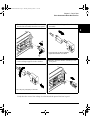
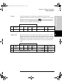
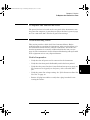
Agilent 34970A/34972A
Data Acquisition /
Switch Unit
Service Guide
Agilent Technologies
Notices
© Agilent Technologies, Inc. 20092012
No part of this manual may be reproduced in any form or by any means
(including electronic storage and
retrieval or translation into a foreign
language) without prior agreement and
written consent from Agilent Technologies, Inc. as governed by United States
and international copyright laws.
Manual Part Number
34972-90010
Third Edition, May 2012
Printed in Malaysia
Agilent Technologies, Inc.
900 S. Taft Ave.
Loveland, CO 80537 USA
Adobe, the Adobe Logo, Acrobat and
the Acrobat Logo are trademarks of
Adobe Systems Incorporated.
Microsoft is either a registered trademark or a trademark of Microsoft Corporation in the United States and/or
other countries.
Windows and MS Windows are U.S.
registered trademarks of Microsoft
Corporation.
Software Updates/Licenses
Periodically, Agilent releases software
updates to fix known defects and incorporate product enhancements. To search for
software updates and the latest documentation for your product, go to the product page
at:
www.agilent.com/find/34970A
www.agilent.com/find/34972A
A portion of the software in this product is
licensed under terms of the General Public
License Version 2 ("GPLv2"). The text of
the license and source code can be found at:
www.agilent.com/find/GPLV2
This product utilizes Microsoft Windows
CE. Agilent highly recommends that all
Windows-based computers connected to
Windows CE instruments utilize current
anti-virus software. For more information,
go to the product page at:
www.agilent.com/find/34970A
www.agilent.com/find/34972A
Technology Licenses
The hardware and/or software
described in this document are furnished under a license and may be used
or copied only in accordance with the
terms of such license.
Declaration of Conformity
Restricted Rights Legend
Declarations of Conformity for this
product and for other Agilent products
may be downloaded from the Web. Go
to http://regulations.corporate.agilent.com and click on "Declarations of
Conformity." You can then search by
product number to find the latest Declaration of Conformity.
If software is for use in the performance of a U.S. Government prime
contract or subcontract, Software is
delivered and licensed as “Commercial
computer software” as defined in
DFAR 252.227-7014 (June 1995), or as
a “commercial item” as defined in FAR
2.101(a) or as “Restricted computer
software” as defined in FAR 52.227-19
(June 1987) or any equivalent agency
regulation or contract clause. Use,
duplication or disclosure of Software is
subject to Agilent Technologies’ standard commercial license terms, and
non-DOD Departments and Agencies
of the U.S. Government will receive no
greater than Restricted Rights as
defined in FAR 52.227-19(c)(1-2)
(June 1987). U.S. Government users
will receive no greater than Limited
Rights as defined in FAR 52.227-14
(June 1987) or DFAR 252.227-7015
(b)(2) (November 1995), as applicable
in any technical data.
Warranty
The material contained in this
document is provided “as is,” and
is subject to being changed, without notice, in future editions.
Further, to the maximum extent
permitted by applicable law, Agilent disclaims all warranties,
either express or implied, with
regard to this manual and any
information contained herein,
including but not limited to the
implied warranties of merchantability and fitness for a particular purpose. Agilent shall not be
liable for errors or for incidental
or consequential damages in connection with the furnishing, use,
or performance of this document
or of any information contained
herein. Should Agilent and the
user have a separate written
agreement with warranty terms
covering the material in this document that conflict with these
terms, the warranty terms in the
separate agreement shall control.
Safety Notices
A CAUTION notice denotes a
hazard. It calls attention to an
operating procedure, practice, or
the like that, if not correctly performed or adhered to, could
result in damage to the product
or loss of important data. Do not
proceed beyond a CAUTION
notice until the indicated conditions are fully understood and
met.
A WARNING notice denotes a
hazard. It calls attention to an
operating procedure, practice, or the like that, if not correctly performed or adhered
to, could result in personal
injury or death. Do not proceed beyond a WARNING
notice until the indicated conditions are fully understood
and met.
Additional Safety Notices
The following general safety precautions must be observed during all
phases of operation of this instrument.
Failure to comply with these precautions or with specific warnings or
instructions elsewhere in this manual
violates safety standards of design,
manufacture, and intended use of the
instrument. Agilent Technologies
assumes no liability of the customer’s
failure to comply with the requirements.
General
Ground the Instrument
This product is provided with protective earth terminals. To minimize shock
hazard, the instrument must be connected to the ac power mains through a
grounded power cable, with the ground
wire firmly connected to an electrical
ground (safety ground) at the power
outlet. Any interruption of the protective (grounding) conductor or disconnection of the protective earth terminal
will cause a potential shock hazard that
could result in personal injury.
Do not use this product in any manner
not specified by the manufacturer. The
protective features of this product may
be impaired if it is used in a manner not
specified in the operation instructions.
Do Not Operate in an
Explosive Atmosphere
Before Applying Power
Do Not Remove the
Instrument Cover
Verify that all safety precautions are
taken. Make all connections to the unit
before applying power and select the
appropriate power line voltage on the
fuse module.
Do not operate the instrument in the
presence of flammable gases or fumes.
Only qualified, service-trained personal
who are aware of the hazards involved
should remove instrument covers.
Always disconnect the power cable and
any external circuits before removing
the instrument cover.
Do Not Modify the
Instrument
Do not install substitute parts or perform any unauthorized modification to
the product. Return the product to an
Agilent Sales and Service Office for
service and repair to ensure that safety
features are maintained.
In Case of Damage
Instruments that appear damaged or
defective should be made inoperative
and secured against unintended operation until they can be repaired by qualified service personnel.
Safety Symbols
Alternating current
Frame or chassis
terminal
Unless otherwise noted in the specifications, this instrument or system is
intended for indoor use in an installation category II, pollution degree 2
environment per IEC 61010-1 and 664
respectively. It is designed to operate at
a maximum relative humidity of 20%
to 80% at 40 °C or less (non-condensing). This instrument or system is
designed to operate at altitudes up to
2000 meters, and at temperatures
between 0 °C and 55 °C.
Standby supply. Unit is not
completely disconnected
from AC mains when
switch is off.
Caution, risk of electric
shock
Caution, refer to
accompanying documents
Technical Support
If you have questions about your
shipment, or if you need
information about warranty,
service, or technical support,
contact Agilent Technologies:
Earth ground terminal
CAT I
IEC Measurement
The CE mark is a
registered trademark of the
European
In the United States: (800) 8294444
The CSA mark is a
registered trademark of the
CSA-International.
In Europe: 31 20 547 2111
The C-tick mark is a
registered trademark of the
Spectrum Management
Agency of Australia. This
signifies compliance with the
Australian EMC Framework
regulations under the terms of
the Radio Communications
In Japan: 0120-421-345
Or go to
www.agilent.com/find/assist
for information on contacting
Agilent in your country of specific
location. You can also contact your
Agilent Technologies
Representative.
Contains one or more of
the 6 hazardous substances
above the maximum
concentration value
(MCV), 40 Year EPUP.
1SM1-
ICES/
NMB
-001
This text indicates that the
instrument is an Industrial
Scientific and Medical
Group 1 Class A product
(CISPER 11, Clause 4).
This text indicates product
compliance with the
Canadian InterferenceCausing Equipment
Standard (ICES-001).
34970A Refresh SG.book Page 5 Thursday, February 4, 2010 11:16 AM
Note: Unless otherwise indicated, this manual applies to all serial numbers.
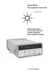
The Agilent Technologies 34970A/34972A combines precision
measurement capability with flexible signal connections for your
production and development test systems. Three module slots are built
into the rear of the instrument to accept any combination of data
acquisition or switching modules. The combination of data logging and
data acquisition features makes this instrument a versatile solution for
your testing requirements now and in the future.
Convenient Data Logging Features
• Direct measurement of thermocouples, RTDs, thermistors, DC
voltage, AC voltage, resistance, DC current, AC current, frequency,
and period
• Interval scanning with storage of up to 50,000 time-stamped readings
• Independent channel configuration with function, Mx+B scaling, and
alarm limits available on a per-channel basis
• Intuitive user interface with knob for quick channel selection, menu
navigation, and data entry from the front panel
• Portable, ruggedized case with non-skid feet
• BenchLink Data Logger 3 Software for Microsoft® Windows ®
included
Flexible Data Acquisition/Switching Features
• 6½-digit multimeter accuracy, stability, and noise rejection
• Up to 60 channels per instrument (120 single-ended channels)
• Reading rates up to 500 readings per second on a single channel and
scan rates up to 250 channels per second
• Choice of multiplexing, matrix, general-purpose Form C switching,
RF switching, digital I/O, totalize, and 16-bit analog output functions
• GPIB (IEEE-488) interface and RS-232 interface are standard on the
34970A. Local Area Network (LAN) and Universal Serial Bus (USB)
are standard on the 34972A.
• SCPI (Standard Commands for Programmable Instruments)
compatibility
Agilent 34970A/34972A
Data Acquisition/Switch Unit
34970A Refresh SG.book Page 6 Thursday, February 4, 2010 11:16 AM
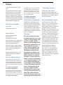
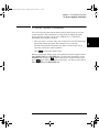
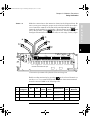
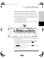
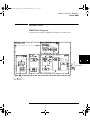
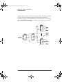
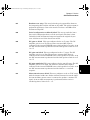
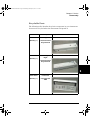
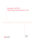
The Front Panel at a Glance
Denotes a menu key. See the next page for details on menu operation.
1
2
3
4
5
6
7
6
State Storage / Remote Interface Menus
Scan Start / Stop Key
Measurement Configuration Menu
Scaling Configuration Menu
Alarm / Alarm Output Configuration Menu
Scan-to-Scan Interval Menu
Scan List Single Step / Read Key
8 Advanced Measurement / Utility Menus
9 Low-Level Module Control Keys
10 Single-Channel Monitor On / Off Key
11 View Scanned Data, Alarms, Errors Menu
12 Shift / Local Key
13 Knob
14 Navigation Arrow Keys
34970A Refresh SG.book Page 7 Thursday, February 4, 2010 11:16 AM
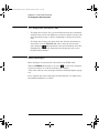
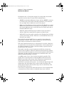
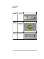
The Front-Panel Menu at a
Glance
Several of the front-panel keys guide you
through menus to configure various
parameters of the instrument (see previous
page). The following steps demonstrate the
menu structure using the
key.
4
1. Press the menu key. You are
automatically guided to the first level of
the menu. Rotate the knob to view the
other choices on the first level of the
menu.
The menu will automatically time out after
about 20 seconds of inactivity. You will be
returned to the operation in progress prior
to entering the menu.
2. Press the same menu key again to move to
the next item of the menu. Typically, this
is where you choose parameter values for
the selected operation.
3. Rotate the knob to view the choices on this
level of the menu. When you reach the end
of the list, rotate the knob in the opposite
direction to view all of the other choices.
The current selection is highlighted for
emphasis. All other choices are dimmed.
4. Press the same menu key again to accept
the change and exit the menu. A brief
confirmation message is displayed.
Tip: To review the current configuration of a specific menu, press the menu key several times.
A message NO CHANGES is displayed when you exit the menu.
7
34970A Refresh SG.book Page 8 Thursday, February 4, 2010 11:16 AM
Display Annunciators
SCAN
MON
VIEW
CONFIG
ADRS
RMT
ERROR
EXT
ONCE
MEM (34970A)
MEM (34972A)
AUTO (34972A)
LAST
MIN
MAX
SHIFT
4W
OC
Scan is in progress or enabled. Press and hold
again to turn off.
Monitor mode is enabled. Press
again to turn off.
Scanned readings, alarms, errors, or relay cycles are being viewed.
Channel configuration is in progress on displayed channel.
Measurement is in progress.
Instrument is addressed to listen or talk over the remote interface.
Instrument is in remote mode (remote interface).
Hardware or remote interface errors are detected. Press
to read errors.
Instrument is configured for an external scan interval.
Scan Once mode is enabled. Press
to initiate and hold key to disable.
Reading memory overflow; new readings will overwrite the oldest readings.
A USB drive is connected to the instrument (annunciator on), or data is
being written to or read from the USB drive (annunciator flashing).
USB logging is active.
Viewed data is the last reading stored during most recent scan.
Viewed data is the minimum reading stored during most recent scan.
Viewed data is the maximum reading stored during most recent scan.
has been pressed. Press
again to turn off.
4-wire function is in use on displayed channel.
Offset compensation is enabled on displayed channel.
Alarms are enabled on displayed channel.
Mx+B scaling is enabled on displayed channel.
HI or LO alarm condition has occurred on indicated alarms.
To review the display annunciators, hold down the
as you turn on the instrument.
8
key
34970A Refresh SG.book Page 9 Thursday, February 4, 2010 11:16 AM
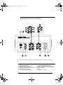
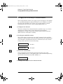
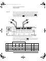
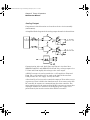
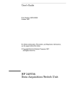
The 34970A Rear Panel at a Glance
4
1 Slot Identifier (100,200, 300)
2 Ext Trig Input / Alarm Outputs / Channel
Advance Input / Channel Closed Output
3 RS-232 Interface Connector
4
5
6
7
Power-Line Fuse-Holder Assembly
Power-Line Voltage Setting
Chassis Ground Screw
GPIB (IEEE-488) Interface Connector
Use the
Menu to:
• Select the GPIB or RS-232 interface (see chapter 2).
• Set the GPIB address (see chapter 2).
• Set the RS-232 baud rate, parity, and flow control mode (see chapter 2).
WARNING
For protection from electrical shock, the power cord ground must not be
defeated. If only a two-contact electrical outlet is available, connect the
instrument’s chassis ground screw (see above) to a good earth ground.
9
34970A Refresh SG.book Page 10 Thursday, February 4, 2010 11:16 AM
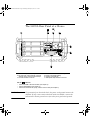
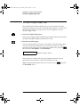
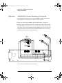
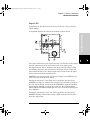
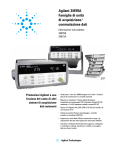
The 34972A Rear Panel at a Glance
ExtT rig / Alarms (5V)
US
168520
ICES/NM
B-001
ISM-A1
LXI Class C
Line: 50/60/400 Hz
100V 120V (127V)
240V 220V (230V)
N10149
Fuse: 500mAT
(250V)
Opt. 001
30 V A Max
1 Slot Identifier (100,200, 300)
2 Chassis Ground Screw
3 Ext Trig Input / Alarm Outputs / Channel
Advance Input / Channel Closed Output
4
5
6
7
LAN
Host
Device
Power-Line Fuse-Holder Assembly
LAN Connector
USB Drive Connector
USB Interface Connector
Use the
Menu to:
• Select and configure the LAN and USB interfaces (see chapter 2).
For protection from electrical shock, the power cord ground must not be
defeated. If only a two-contact electrical outlet is available, connect the
instrument’s chassis ground screw (see above) to a good earth ground.
WARNING
10
34970A Refresh SG.book Page 11 Thursday, February 4, 2010 11:16 AM
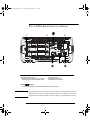
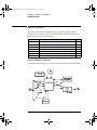
The Plug-In Modules at a Glance
For complete specifications on each plug-in modules, refer to the module
sections in chapter 8.
34901A 20-Channel Armature Multiplexer
• 20 channels of 300 V switching
• Two channels for DC or AC current measurements (100 nA to 1A)
4
• Built-in thermocouple reference junction
• Switching speed of up to 60 channels per second
• Connects to the internal multimeter
• For detailed information and a module diagram, see page 152.
Each of the 20 channels switches both HI and LO inputs, thus providing
fully isolated inputs to the internal multimeter. The module is divided
into two banks of 10 two-wire channels each. When making four-wire
resistance measurements, channels from Bank A are automatically
paired with channels from Bank B. Two additional fused channels are
included on the module (22 channels total) for making calibrated DC or
AC current measurements with the internal multimeter (external shunt
resistors are not required). You can close multiple channels on this
module only if you have not configured any channels to be part of the
scan list. Otherwise, all channels on the module are break-before-make.
34902A 16-Channel Reed Multiplexer
• 16 channels of 300 V switching
• Built-in thermocouple reference junction
• Switching speed of up to 250 channels per second
• Connects to the internal multimeter
• For detailed information and a module diagram, see page 154.
Use this module for high-speed scanning and high-throughput
automated test applications. Each of the 16 channels switches both HI
and LO inputs, thus providing fully isolated inputs to the internal
multimeter. The module is divided into two banks of eight two-wire
channels each. When making four-wire resistance measurements,
channels from Bank A are automatically paired with channels from Bank
B. You can close multiple channels on this module only if you have not
configured any channels to be part of the scan list. Otherwise, all
channels on the module are break-before-make.
11
34970A Refresh SG.book Page 12 Thursday, February 4, 2010 11:16 AM
34903A
20-Channel Actuator / General-Purpose Switch
• 300 V, 1 A actuation and switching
• SPDT (Form C) latching relays
• Breadboard area for custom circuits
• For detailed information and a module diagram, see page 156.
Use this module for those applications that require high-integrity
contacts or quality connections of non-multiplexed signals. This module
can switch 300 V, 1 A (50 W maximum switch power) to your device
under test or to actuate external devices. Screw terminals on the module
provide access to the Normally-Open, Normally-Closed, and Common
contacts for each of the 20 switches. A breadboard area is provided near
the screw terminals to implement custom circuitry, such as simple
filters, snubbers, or voltage dividers.
34904A 4x8 Two-Wire Matrix Switch
• 32 two-wire crosspoints
• Any combination of inputs and outputs can be connected at a time
• 300 V, 1 A switching
• For detailed information and a module diagram, see page 157.
Use this module to connect multiple instruments to multiple points on
your device under test at the same time. You can connect rows and
columns between multiple modules to build larger matrices such as 8x8
and 4x16, with up to 96 crosspoints in a single mainframe.
34905/6A Dual 4-Channel RF Multiplexers
• 34905A (50) / 34906A (75)
• 2 GHz bandwidth with on-board SMB connections
• 1 GHz bandwidth with SMB-to-BNC adapter cables provided
• For detailed information and a module diagram, see page 158.
These modules offer wideband switching capabilities for high frequency
and pulsed signals. Each module is organized in two independent banks
of 4-to-1 multiplexers. Both modules offer low crosstalk and excellent
insertion loss performance. To create larger RF multiplexers, you can
cascade multiple banks together. Only one channel in each bank may be
closed at a time.
12
34970A Refresh SG.book Page 13 Thursday, February 4, 2010 11:16 AM
34907A Multifunction Module
• Two 8-bit Digital Input/Output ports, 400 mA sink, 42 V open
collector
• 100 kHz Totalize input with 1 Vpp sensitivity
• Two 16-bit, ±12 V Calibrated Analog Outputs
• For detailed information and module block diagrams, see page 161.
Use this module to sense status and control external devices such as
solenoids, power relays, and microwave switches. For greater flexibility,
you can read digital inputs and the count on the totalizer during a scan.
4
34908A 40-Channel Single-Ended Multiplexer
• 40 channels of 300 V single-ended (common LO) switching
• Built-in thermocouple reference junction
• Switching speed of up to 60 channels per second
• Connects to the internal multimeter
• For detailed information and a module diagram, see page 159.
Use this module for high-density switching applications which require
single-wire inputs with a common LO. All relays are break-before-make
to ensure that only one relay is connected at any time.
13
34970A Refresh SG.book Page 14 Thursday, February 4, 2010 11:16 AM
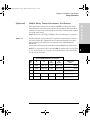
In This Book
Specifications Chapter 1 lists the technical specifications for the
mainframe and plug-in modules.
Quick Start Chapter 2 helps you get familiar with a few of the
instrument’s front-panel features.
Front-Panel Overview Chapter 3 introduces you to the front-panel
menus and describes some of the instrument’s menu features.
Calibration Procedures Chapter 4 provides calibration, verification,
and adjustment procedures for the instrument.
Theory of Operation Chapter 5 describes block and circuit level
theory related to the operation the instrument.
Service Chapter 6 provides guidelines for returning your instrument to
Agilent Technologies for servicing, or for servicing it yourself. It also
contains a list of replaceable parts.
If you have questions relating to the operation of the 34970A/
34972A, call 1-800-452-4844 in the United States, or contact
your nearest Agilent Technologies Sales Office.
If your 34970A/34972A fails within one year of original
purchase, Agilent will replace it free of charge. Call 1-800-8294444 and select "Option 3" followed by "Option 1".
14
34970A Refresh SG.book Page 15 Thursday, February 4, 2010 11:16 AM
Contents
Chapter 1 Specifications
22
Contents
DC, Resistance, and Temperature Accuracy Specifications
DC Measurement and Operating Characteristics 23
AC Accuracy Specifications 24
AC Measurement and Operating Characteristics 25
System Characteristics 26
System Speed Specifications [1] 27
System Speed Specifications 28
Module Specifications 29
Module Specifications 30
Typical AC Performance Graphs 31
Module Specifications 32
Product and Module Dimensions 33
To Calculate Total Measurement Error 34
Interpreting Internal DMM Specifications 36
Configuring for Highest Accuracy Measurements 39
Chapter 2 Quick Start
To Prepare the Instrument for Use 43
To Connect Wiring to a Module 44
To Set the Time and Date 46
To Configure a Measurement Channel 47
To Monitor a Single Channel 48
To Close a Channel 49
If the Instrument Does Not Turn On 50
To Adjust the Carrying Handle 52
To Rack Mount the Instrument 53
15
34970A Refresh SG.book Page 16 Thursday, February 4, 2010 11:16 AM
Contents
Chapter 3 Front-Panel Overview
Front-Panel Menu Reference 57
To Unsecure for Calibration 60
To Secure Against Calibration 61
To Change the Security Code 62
Error Messages 62
To Perform a Zero Adjustment 63
To Apply Mx+B Scaling to Measurements
To Read the Relay Cycle Count 65
To Read a Digital Input Port 66
To Write to a Digital Output Port 67
To Read the Totalizer Count 68
To Output a DC Voltage 69
64
Contents
Chapter 4 Calibration Procedures
Agilent Technologies Calibration Services 73
Calibration Interval 73
Adjustment is Recommended 73
Time Required for Calibration 74
Automating Calibration Procedures 74
Recommended Test Equipment 75
Input Connections 76
Calibration Security 77
To Unsecure the Instrument Without the Security Code
Calibration Message 79
Calibration Count 79
Calibration Procedure 80
Aborting a Calibration in Progress 80
Test Considerations 81
Performance Verification Tests 82
Self-Test 83
Quick Performance Check 84
Performance Verification Tests 84
Internal DMM Verification Tests 85
Zero Offset Verification 85
Gain Verification 87
Optional AC Performance Verification Tests 90
Internal DMM Adjustments 91
Zero Adjustment 91
16
78
34970A Refresh SG.book Page 17 Thursday, February 4, 2010 11:16 AM
Contents
Contents
Gain Adjustment 92
–10 VDC Adjustment Procedure (Optional) 95
Plug-in Module Test Considerations 97
Relay Verification 98
Relay Cycle Count 98
34901A Relay Contact Resistance Verification 99
34902A Relay Contact Resistance Verification 106
34903A Relay Contact Resistance Verification 111
34904A Relay Contact Resistance Verification 112
34905/06A Relay Contact Resistance Verification 115
34908A Relay Contact Resistance Verification 116
Thermocouple Reference Junction (Optional) 122
Thermocouple Reference Junction Verification 122
Thermocouple Reference Junction Adjustments 123
34907A Analog Output 124
Analog Output Verification Test 124
Analog Output Adjustment 125
Chapter 5 Theory of Operation
System Block Diagram 129
Floating Logic 130
Memory 133
Earth-Referenced Logic 134
Power Supplies 135
Front Panel 137
Backplane 138
Analog Bus 138
Digital Bus 138
Internal DMM 139
DMM Block Diagram 139
Input 140
Input Amplifier 141
Ohms Current Source 143
AC Circuit 144
A-to-D Converter 146
Switch Modules 148
Switch Module Control 148
Relay Drivers 150
34901A 152
17
34970A Refresh SG.book Page 18 Thursday, February 4, 2010 11:16 AM
Contents
34902A 154
34903A 156
34904A 157
34905A/34906A 158
34908A 159
Multifunction Module 161
Multifunction Control 161
Totalizer 163
Analog Output 164
Digital I/O 165
Contents
Chapter 6 Service
Operating Checklist 169
Is the instrument inoperative? 169
Does the instrument fail self-test? 169
Is the Current measurement function inoperative?
Types of Service Available 170
Agilent Unit Exchange 170
Repackaging for Shipment 171
Cleaning 171
Electrostatic Discharge (ESD) Precautions 172
Surface Mount Repair 172
To Replace the Power-Line Fuse 173
Troubleshooting Hints 173
Unit is Inoperative 173
Unit Reports Error 705 174
Isolating to an Assembly 174
Unit Fails Self-Test 174
Power Supplies 175
Self-Test Procedures 177
Power-On Self-Test 177
Complete Self-Test 177
Plug-in Module Self-Test 177
Self-Tests 178
Disassembly 183
General Disassembly 184
Internal DMM Disassembly 185
Front Panel Disassembly 186
Additional Chassis Disassembly 187
18
169
34970A Refresh SG.book Page 19 Thursday, February 4, 2010 11:16 AM
Contents
Plug-In Module Disassembly 188
Recyclable Parts 189
Replaceable Parts 192
To Order Replaceable Parts 192
Parts List for 34970A/34972A and 34901A
193
Contents
19
34970A Refresh SG.book Page 20 Thursday, February 4, 2010 11:16 AM
Contents
Contents
20
34970A Refresh SG.book Page 21 Thursday, February 4, 2010 11:16 AM
1
1
• DC, Resistance, and Temperature Accuracy Specifications, on page 22
• DC Measurement and Operating Characteristics, on page 23
• AC Accuracy Specifications, on page 24
• AC Measurement and Operating Characteristics, on page 25
• System Characteristics, on page 26
• Module Specifications - 34901A, 34902A, 34908A, 34903A, 34904A, on
page 29
• Module Specifications - 34905A, 34906A, on page 30
• Typical AC Performance Graphs - 34905A, 34906A, on page 31
• Module Specifications - 34907A, on page 32
• BenchLink Data Logger 3 Software Specifications, on page 32
• Product and Module Dimensions, on page 33
• To Calculate Total Measurement Error, on page 34
• Interpreting Internal DMM Specifications, on page 36
• Configuring for Highest Accuracy Measurements, on page 39
Specifications
34970A Refresh SG.book Page 22 Thursday, February 4, 2010 11:16 AM
Chapter 1 Specifications
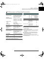
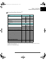
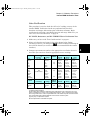
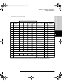
DC, Resistance, and Temperature Accuracy Specifications
DC, Resistance, and Temperature Accuracy Specifications
± (% of reading + % of range) [1]
Includes measurement error, switching error, and transducer conversion error
Function
Range[3]
Test Current or
Burden Voltage
Temperature
Coefficient /°C
0 °C - 18 °C
28 °C - 55 °C
24 Hour[2]
23 °C ± 1 °C
90 Day
23 °C ± 5 °C
0.0030 + 0.0035
0.0020 + 0.0006
0.0015 + 0.0004
0.0020 + 0.0006
0.0020 + 0.0020
0.0040 + 0.0040
0.0030 + 0.0007
0.0020 + 0.0005
0.0035 + 0.0006
0.0035 + 0.0030
0.0050 + 0.0040
0.0040 + 0.0007
0.0035 + 0.0005
0.0045 + 0.0006
0.0045 + 0.0030
0.0005 + 0.0005
0.0005 + 0.0001
0.0005 + 0.0001
0.0005 + 0.0001
0.0005 + 0.0003
1 Year
23 °C ± 5 °C
DC Voltage
100.0000 mV
1.000000 V
10.00000 V
100.0000 V
300.000 V
Resistance[4]
100.0000
1.000000 k
10.00000 k
100.0000 k
1.000000 M
10.00000 M
100.0000 M
1 mA current source
1 mA
100 A
10 A
5 A
500 nA
500nA || 10 M
0.0030 + 0.0035
0.0020 + 0.0006
0.0020 + 0.0005
0.0020 + 0.0005
0.002 + 0.001
0.015 + 0.001
0.300 + 0.010
0.008 + 0.004
0.008 + 0.001
0.008 + 0.001
0.008 + 0.001
0.008 + 0.001
0.020 + 0.001
0.800 + 0.010
0.010 + 0.004
0.010 + 0.001
0.010 + 0.001
0.010 + 0.001
0.010 + 0.001
0.040 + 0.001
0.800 + 0.010
0.0006 + 0.0005
0.0006 + 0.0001
0.0006 + 0.0001
0.0006 + 0.0001
0.0010 + 0.0002
0.0030 + 0.0004
0.1500 + 0.0002
DC Current
34901A Only
10.00000 mA
100.0000 mA
1.000000 A
< 0.1 V burden
<0.6 V
<2 V
0.005 + 0.010
0.010 + 0.004
0.050 + 0.006
0.030 + 0.020
0.030 + 0.005
0.080 + 0.010
0.050 + 0.020
0.050 + 0.005
0.100 + 0.010
0.002 + 0.0020
0.002 + 0.0005
0.005 + 0.0010
Temperature
Type
Thermocouple[6]
B
E
J
K
N
R
S
T
1-Year Best Range Accuracy[5]
1100°C to 1820°C
-150°C to 1000°C
-150°C to 1200°C
-100°C to 1200°C
-100°C to 1300°C
300°C to 1760°C
400°C to 1760°C
-100°C to 400°C
1.2°C
1.0°C
1.0°C
1.0°C
1.0°C
1.2°C
1.2°C
1.0°C
Extended Range Accuracy [5]
400°C to 1100°C
-200°C to -150°C
-210°C to -150°C
-200°C to -100°C
-200°C to -100°C
-50°C to 300°C
-50°C to 400°C
-200°C to -100°C
1.8°C
1.5°C
1.2°C
1.5°C
1.5°C
1.8°C
1.8°C
1.5°C
Temperature
Coefficient /°C
0.03°C
0.03°C
0.03°C
0.03°C
0.03°C
0.03°C
0.03°C
0.03°C
RTD
R0 from 49
to 2.1 k
-200°C to 600°C
0.06°C
0.003°C
Thermistor
2.2 k, 5 k, 10 k
-80°C to 150°C
0.08°C
0.002°C
[1] Specifications are for 1 hour warm up and 6½ digits, slow AC filter.
[2] Relative to calibration standards.
[3] 20% over range on all ranges except 300 VDC and 1 Adc ranges.
[4] Specifications are for 4-wire ohms function or 2-wire ohms using Scaling to remove the offset.
Without Scaling, add 4 additional error in 2-wire ohms function.
[5] 1 year accuracy. For total measurement accuracy, add temperature probe error.
[6] Thermocouple specifications are not guaranteed when 34907A module is present.
22
34970A Refresh SG.book Page 23 Thursday, February 4, 2010 11:16 AM
Chapter 1 Specifications
DC Measurement and Operating Characteristics
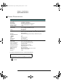
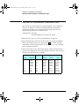
DC Measurement and Operating Characteristics
DC Measurement Characteristics [1]
DC Voltage
Measurement Method:
A/D Linearity:
Input Resistance:
100 mV, 1V, 10 V ranges
100 V, 300 V ranges
Input Bias Current:
Input Protection:
Resistance
Measurement Method:
Function
DCV, DCI, and
Resistance:
Selectable 10 M or > 10 G
10 M ±1%
< 30 pA at 25 °C
300 V on all ranges
Single Channel Measurement Rates [8]
Input Protection:
DC Current
Shunt Resistance:
Input Protection:
5 for 10 mA, 100 mA; 0.1 for 1A.
1.5A 250 V fuse on 34901A module
Thermocouple
Conversion:
Reference Junction Type:
Open T/C Check:
ITS-90 software compensation
Internal, Fixed, or External
Selectable per channel. Open > 5 k
Max. Lead Resistance:
RTD
Thermistor
Digits[6]
6½
6½
5½
5½
4½
Continuously Integrating
Multi-slope III A/D Converter
0.0002% of reading + 0.0001% of
range
Selectable 4-wire or 2-wire Ohms
Current source reference to LO input
Selectable on 100, 1k, 10k
ranges
10% of range per lead for 100 and
1 k ranges. 1 k on all other
ranges
300 V on all ranges
Offset compensation:
DC Operating Characteristics [5]
- 0.00385 (DIN/IEC 751) using
ITS-90 software compensation or
= 0.00391 using IPTS-68 software
compensation.
44004, 44007, 44006 series
Measurement Noise Rejection 60 Hz (50 Hz) [2]
DC CMRR:
140 dB
Integration Time
200 PLC / 3.33s (4s)
100 PLC / 1.67s (2s)
20 PLC / 333 ms (400 ms)
10 PLC / 167 ms (200 ms)
2 PLC / 33.3 ms (40 ms)
1 PLC / 16.7 ms (20 ms)
< 1PLC
Normal Mode Rejection [3]
110 dB[4]
105 dB[4]
100 dB[4]
95 dB[4]
90 dB
60 dB
0 dB
Readings/s
0.6 (0.5)
6 (5)
60 (50)
300
600
Additional
Noise Error
0% of range
0% of range
0.001% of range
0.001% of range [7]
0.01% of range [7]
4
Function
Resolution
DCV, 2-Wire Ohms: 6½ (10 PLC)
5½ (1 PLC)
4½ (0.02 PLC)
Readings/s
6 (5)
54 (47)
500
Thermocouple:
0.1 °C (10 PLC)
0.1 °C (1 PLC)
(0.02 PLC)
6 (5)
52 (47)
280
RTD, Thermistor:
0.01 °C (10 PLC)
0.1 °C (1 PLC)
1 °C (0.02 PLC)
6 (5)
49 (47)
200
Autozero OFF Operation
Following instrument warm-up at calibration temperature ±1 °C
and < 10 minutes, add 0.0002% range additional error + 5 V.
Settling Consideration
Reading settling times are affected by source impedance, low
dielectric absorption characteristics, and input signal changes.
[1] Isolation voltage (ch-ch, ch-earth) 300 VDC, AC rms
[2] For 1 k unbalance in LO lead
[3] For power line frequency ±0.1%
[4] For power line frequency ±1%, use 80 dB
For power line frequency ±3%, use 60 dB
[5] Reading speeds for 60 Hz and (50 Hz) operation;
autozero OFF
[6] 6½ digits=22 bits, 5½ digits=18 bits, 4½ digits=15 bits
[7] Add 20 V for DCV, 4 A for DCI, or 20 m for
resistance
[8] For fixed function and range, readings to memory,
scaling and alarms off, autozero OFF
23
1
34970A Refresh SG.book Page 24 Thursday, February 4, 2010 11:16 AM
Chapter 1 Specifications
AC Accuracy Specifications
AC Accuracy Specifications
± (% of reading + % of range) [1]
Includes measurement error, switching error, and transducer conversion error
Function
True RMS
AC Voltage [4]
Frequency
and Period[6]
True RMS
AC Current
34901A Only
Range[3]
24 Hour[2]
23 °C ± 1 °C
Frequency
1 Year
23 °C ± 5 °C
Temperature
Coefficient /°C
0 °C - 18 °C
28 °C - 55 °C
100.0000 mV
to 100 V
3 Hz - 5 Hz
5 Hz - 10 Hz
10 Hz - 20 kHz
20 kHz - 50 kHz
50 kHz - 100 kHz
100 kHz - 300 kHz[5]
1.00 + 0.03
0.35 + 0.03
0.04 + 0.03
0.10 + 0.05
0.55 + 0.08
4.00 + 0.50
1.00 + 0.04
0.35 + 0.04
0.05 + 0.04
0.11 + 0.05
0.60 + 0.08
4.00 + 0.50
1.00 + 0.04
0.35 + 0.04
0.06 + 0.04
0.12 + 0.05
0.60 + 0.08
4.00 + 0.50
0.100 + 0.004
0.035 + 0.004
0.005 + 0.004
0.011 + 0.005
0.060 + 0.008
0.20 + 0.02
300.0000 V
3 Hz - 5 Hz
5 Hz - 10 Hz
10 Hz - 20 kHz
20 kHz - 50 kHz
50 kHz - 100 kHz
100 kHz - 300 kHz[5]
1.00 + 0.05
0.35 + 0.05
0.04 + 0.05
0.10 + 0.10
0.55 + 0.20
4.00 + 1.25
1.00 + 0.08
0.35 + 0.08
0.05 + 0.08
0.11 + 0.12
0.60 + 0.20
4.00 + 1.25
1.00 + 0.08
0.35 + 0.08
0.06 + 0.08
0.12 + 0.12
0.60 + 0.20
4.00 + 1.25
0.100 + 0.008
0.035 + 0.008
0.005 + 0.008
0.011 + 0.012
0.060 + 0.020
0.20 + 0.05
0.10
0.05
0.03
0.006
0.10
0.05
0.03
0.01
100 mV
to
300 V
3 Hz - 5 Hz
5 Hz - 10 Hz
10 Hz - 40 Hz
40 Hz - 300 kHz
0.10
0.05
0.03
0.01
0.005
0.005
0.001
0.001
10.00000 mA[4]
and
1.000000 A[4]
3 Hz - 5 Hz
5 Hz - 10 Hz
10 Hz - 5 kHz
1.00 + 0.04
0.30 + 0.04
0.10 + 0.04
1.00 + 0.04
0.30 + 0.04
0.10 + 0.04
1.00 + 0.04
0.30 + 0.04
0.10 + 0.04
0.100 + 0.006
0.035 + 0.006
0.015 + 0.006
100.0000 mA[7]
3 Hz - 5 Hz
5 Hz - 10 Hz
10 Hz - 5 kHz
1.00 + 0.5
0.30 + 0.5
0.10 + 0.5
1.00 + 0.5
0.30 + 0.5
0.10 + 0.5
1.00 + 0.5
0.30 + 0.5
0.10 + 0.5
0.100 + 0.06
0.035 + 0.06
0.015 + 0.06
Additional Low Frequency Error for ACV, ACI (% of reading)
Frequency
10 Hz - 20 Hz
20 Hz - 40 Hz
40 Hz - 100 Hz
100 Hz - 200 Hz
200 Hz - 1 kHz
> 1 kHz
90 Day
23 °C ± 5 °C
AC Filter
Slow
0
0
0
0
0
0
AC filter
Medium
0.74
0.22
0.06
0.01
0
0
AC Filter
Fast
--0.73
0.22
0.18
0
Additional Error for Frequency, Period (% of reading)
Frequency
3 Hz - 5 Hz
5 Hz - 10 Hz
10 Hz - 40 Hz
40 Hz - 100 Hz
100 Hz - 300 Hz
300 Hz - 1 kHz
>1 kHz
6½ Digits
0
0
0
0
0
0
0
5½ Digits
0.12
0.17
0.2
0.06
0.03
0.01
0
4½ Digits
0.12
0.17
0.2
0.21
0.21
0.07
0.02
[1] Specifications are for 1 hour warm up and 6½ digits, Slow AC filter
[2] Relative to calibration standards
[3] 20% over range on all ranges except 300 VAC and 1 A ac rangesand AC current ranges.
[4] For sinewave input >5% of range. For inputs from 1% to 5% of range and <50 kHz, add 0.1% of range additional error.
[5] Typically 30% of reading error at 1 MHz, limited to 1x10⁸ V Hz
[6] Input > 100 mV. For 10 mV to 100 mV inputs, multiply % of reading error x 10.
[7] Specified only for inputs > 10 mA
24
34970A Refresh SG.book Page 25 Thursday, February 4, 2010 11:16 AM
Chapter 1 Specifications
AC Measurement and Operating Characteristics
AC Measurement and Operating Characteristics
AC Measurement Characteristics [1]
AC Operating Characteristics [4]
True RMS AC Voltage
Measurement Method:
Function
ACV, ACI:
Crest Factor:
Additional Crest Factor
Errors (non-sinewave):[2]
AC Filter Bandwidth:
Slow
Medium
Fast
Input Impedance:
Input Protection:
Frequency and Period
Measurement Method:
Voltage Ranges:
Gate Time:
Measurement Timeout:
True RMS AC Current
Measurement Method:
Shunt Resistance:
Input Protection:
AC-coupled True RMS -measures
the AC component of input with up to
300 VDC of bias on any range
Maximum 5:1 at Full Scale
Crest Factor 1-2:
Crest Factor 2-3:
Crest Factor 3-4:
Crest Factor 4-5:
0.05% of reading
0.15% of reading
0.30% of reading
0.40% of reading
3 Hz - 300 kHz
20 Hz - 300 kHz
200 Hz - 300 kHz
1 M ±2%, in parallel with 150 pF
300 Vrms on all ranges
Reciprocal counting technique
Same as AC Voltage function
1s, 100 ms, or 10 ms
Selectable 3 Hz, 20 Hz, 200 Hz LF
limit
Direct coupled to the fuse and shunt.
AC-coupled True RMS
measurement (measures the AC
component only)
5 for 10 mA; 0.1 for 100 mA, 1A
1.5A 250 V fuse on 34901A module
Measurement Noise Rejection [3]
AC CMRR:
70 dB
Digits[5]
6½
6½
6½
6½
6½
Readings/s
7 sec/reading
1
8[6]
10
100[7]
AC Filter
Slow (3 Hz)
Medium (20 Hz)
Fast (200 Hz)
Fast (200 Hz)
Fast (200 Hz)
4
Single Channel Measurement Rates [8]
Function
ACV:
Resolution
6½ Slow (3 Hz)
6½ Medium (20 Hz)
6½ Fast (200 Hz)
6½[7]
Frequency, Period: 6½ Digits (1s gate)
5½ Digits (100 ms)
4½ Digits (10 ms)
Readings/s
0.14
1
8
100
1
9
70
[1] Isolation voltage (ch-ch, ch-earth) 300 VDC, AC rms
[2] For frequencies below 100 Hz, slow AC filter specified for
sinewave input only
[3] For 1 k unbalance in LO lead
[4] Maximum reading rates for 0.01% of AC step additional
error. Additional settling delay required when input DC
level varies.
[5] 6½ digits=22 bits, 5½ digits=18 bits, 4½ digits=15 bits
[6] For external trigger or remote operation using default
settling delay (Delay Auto)
[7] Maximum limit with default settling delays defeated
[8] For fixed function and range, readings to memory, scaling
and alarms turned off.
Measurement Considerations (Frequency and Period)
All frequency counters are susceptible to error when measuring lowvoltage, low-frequency signals, Shielding inputs from external noise
pickup is critical for minimizing measurement errors.
25
1
34970A Refresh SG.book Page 26 Thursday, February 4, 2010 11:16 AM
Chapter 1 Specifications
System Characteristics
System Characteristics
System Characteristics
Scan Triggering
Scan Count:
Scan Interval:
Channel Delay:
External Trig Delay:
External Trig Jitter:
1 to 50,000 or continuous
0 to 99 hours; 1 ms step size
0 to 60 seconds/channel; 1 ms step size
< 300 s; With Monitor On, < 200 ms
< 2 ms
Alarms
Alarm Outputs:
4 TTL compatible. Selectable TTL logic
HI or LO on Fail
5 ms (typical)
Latency:
Memory
Readings:
Time Stamp Resolution:
Relative
Absolute
States:
Alarm Queue:
USB Drive:
General Specifications
Power Supply:
Power Line Frequency:
Power Consumption:
Operating Environment:
Storage Environment:
Weight (Mainframe):
Safety:
RFI and ESD:
Warranty:
Battery Backed, 34970A - 4 year typical life[1]
34972A - User-replaceable battery, recommended replacement during
yearly calibration.
50,000 internal readings with timestamp, readable during scan.
1 ms
1s
5 instrument states
Up to 20 events
FAT or FAT32 format
100 V / 120 V / 220 V/240 V ±10%
45 Hz to 60 Hz automatically sensed
(12 W) 25 VA peak
Full accuracy for 0 °C to 55 °C
Full accuracy to 80% R.H. at 40 °C
-40 °C to 70 °C[1]
Net: 3.6 kg (8.0 lbs)
Conforms to CSA, US-1244, IEC 1010 CAT I
CISPR 11, IEC 801/2/3/4
1 year
[1] Storage at temperatures above 40 °C will decrease battery life.
This ISM device complies with Canadian ICES-001.
Cet appareil ISM est conforme à norme NMB-001 du Canada.
N10149
26
34970A Refresh SG.book Page 27 Thursday, February 4, 2010 11:16 AM
Chapter 1 Specifications
System Speed Specifications [1]
System Speed Specifications [1]
Single Channel Reading Rates to I/O or internal
memory
34970A
34972A
into Memory
to GPIB or
RS232
to LAN, USB
or Memory
readings/sec
readings/sec
readings/sec
500
440
500
Single Channel while changing scale (eg MEAS dcV
10 / MEAS dcV 1)
25
25
25
Single Channel while changing function (eg MEAS
dcV / MEAS Ohms)
12
12
12
Single Channel ASCII dcV readings
Scanning Measurement Rates to I/O or internal
memory
34970A
4
34972A
into Memory
to GPIB or
RS232
to LAN, USB
or Memory
ch/sec
ch/sec
ch/sec
Scanning DCV or Ohms channels
34901A/34908A
60
60
60
34902A
250
210
240
--
180
240
34902A into and out of memory (using INIT, FETCh)
34902A with timestamp (using MEAS)
--
150
240
34902A with scaling and alarms
220
190
220
34902A DCV and ohms on alternate channels
80
80
80
34901A/34908A
50
50
50
34902A
100
90
100
34901A/34908A
50
50
50
34902A
150
150
150
34907A Digital Input
275
250
275
34907A Totalizer
240
210
240
Scanning ACV channels [2]
Scanning Temperature - Thermistor or T/C channels
Scanning Digital In/Totalizer channels
[1] Speeds are for 4½ digits, delay 0, display off, autozero off, unless otherwise noted. Use MEAS command for best I/O
performance. RS232 at 115Kbaud.
[2] Maximum, with default delays defeated.
27
1
34970A Refresh SG.book Page 28 Thursday, February 4, 2010 11:16 AM
Chapter 1 Specifications
System Speed Specifications
System Speed Specifications
Data out of memory [3][4]
(FETCh of 50K readings)
34970A
34972A
over GPIB
over RS232
over USB
over LAN or
memory
readings/sec
readings/sec
readings/sec
readings/sec
Readings
800
600
55K
120K
Readings with timestamp
450
320
35K
60K
Readings with all format options ON.
310
230
25K
50K
[3] Assumes relative time format (time since start of scan)
[4] Typical rates assuming lightly loaded PC and limited other traffic on I/Os. LAN rates assume use of socket connection;
VXI11 will be less.
[5] For fixed function and range, readings to memory, scaling/alarms/autozero off
28
34970A Refresh SG.book Page 29 Thursday, February 4, 2010 11:16 AM
Chapter 1 Specifications
Module Specifications
Module Specifications
34901A, 34902A, 34908A, 34903A, 34904A
Multiplexer
General
Number of Channels
Connects to Internal DMM
Actuator
Matrix
34901A
34902A
34908A
34903A
20+2
16
40
20
34904A
4x8
2/4 wire
2/4 wire
1 wire
SPDT
2 wire
No
No
Yes
Yes
Yes
Scanning Speed [1]
60 ch/s
250 ch/s
60 ch/s
Open/Close Speed
120/s
120/s
70/s
120/s
120/s
300 V
4
Maximum Input
Voltage (dc, AC rms)
300 V
300 V
300 V
300 V
Current (dc, AC rms)
1A
50 mA
1A
1A
1A
50 W
2W
50W
50W
50W
300 V
300 V
300 V
300 V
300 V
< 3 V
<6 V
< 3 V
< 3 V
< 3 V
Power (W, VA)
Isolation (ch-ch, ch-earth)
dc, AC rms
DC Characteristics
Offset Voltage [2]
[2]
Initial Closed Channel R
<1
<1
<1
< 0.2
<1
Isolation (ch-ch, ch-earth)
> 10 G
> 10 G
> 10 G
> 10 G
> 10 G
10 MHz
10 MHz
10 MHz
10 MHz
10 MHz
-45
-45
-18[4]
-45
-33
AC Characteristics
Bandwidth
Ch-Ch Cross Talk (dB)[3]
10 MHz
Capacitance
HI to LO
< 50 pF
< 50 pF
< 50 pF
< 10 pF
< 50 pF
Capacitance
LO to Earth
< 80 pF
< 80 pF
< 80 pF
< 80 pF
< 80 pF
108
108
108
108
108
(typical)
0.8 °C
0.8 °C
0.8 °C[7]
Switch Life
No Load (typical)
100M
100M
100M
100M
100M
Switch Life
Rated Load (typical) [6]
100k
100k
100k
100k
100k
Volt-Hertz Limit
Other
T/C cold Junction Accuracy[2] [5]
Temperature
Operating
Temperature
Storage
Humidity (non-condensing)
All Modules: 0 °C to 55 °C
All Modules: -20 °C to 70 °C
All Modules: 40 °C / 80% R.H.
[1] See scanning rate specifications for measurement conditions and rates on each instrument.
[2] Errors included in the DMM measurement accuracy specifications
[3] 50 source, 50 load
[4] Isolation within channel 1 to 20 or 21 to 40 banks is -40 dB
[5] Thermocouple specifications not guaranteed when 34907A module is present
[6] Applies to resistive loads only
[7] Thermocouple measurements not recommended with 34908A module due to common LO configuration.
29
1
34970A Refresh SG.book Page 30 Thursday, February 4, 2010 11:16 AM
Chapter 1 Specifications
Module Specifications
Module Specifications
34905A, 34906A
RF Multiplexer
General
Number of Channels
Open/Close Speed
34905A
34906A
Dual 1x4
50
Dual 1x4
75
60/s
The AC performance graphs are shown on the following page.
AC Characteristics
Bandwidth[3]
Insertion Loss (dB)
Maximum Input
34905A
34906A
2 GHz
2 GHz
10 MHz
-0.1
-0.1
100 MHz
-0.4
-0.4
Voltage (dc, AC rms)
42 V
500 MHz
-0.6
-0.5
Current (dc, AC rms)
0.7 A
1 GHz
-1.0
-1.0
Power (W, VA)
20 W
1.5 GHz
-1.2
1.5
2 GHz
-3.0
-2.0
DC Characteristics
Offset Voltage [1]
< 6 V
10 MHz
1.02
1.02
Initial Closed Channel R[1]
< 0.5
100 MHz
1.05
1.05
Isolation (ch-ch, ch-earth)
> 1 G
500 MHz
1.20
1.25
1 GHz
1.20
1.40
1.5 GHz
1.30
1.40
SWR
Other
Switch Life
No Load (typical)
Switch Life
Rated Load (typical) [2]
Temperature
Operating
Temperature
Storage
Humidity (non-condensing)
5M
100k
1.40
2.00
10 MHz
-100
-85
-20 °C to 70 °C
100 MHz
-85
-75
40 °C/ 80% R.H.
500 MHz
-65
-65
1 GHz
-55
-50
1.5 GHz
-45
-40
2 GHz
-35
-35
0 °C to 55 °C
2 GHz
Ch-Ch Cross Talk (db)[4]
Risetime
< 300 ps
Signal Delay
Capacitance
Volt-Hertz Limit
30
< 3 ns
HI to LO
<20 pF
1010
34970A Refresh SG.book Page 31 Thursday, February 4, 2010 11:16 AM
Chapter 1 Specifications
Typical AC Performance Graphs
Typical AC Performance Graphs
34905A, 34906A
Insertion Loss (50)
Insertion Loss (75)
4
Direct to Module
Using provided adapter cables
VSWR (50)
VSWR (75)
Crosstalk (50)
Crosstalk (75)
31
1
34970A Refresh SG.book Page 32 Thursday, February 4, 2010 11:16 AM
Chapter 1 Specifications
Module Specifications
Module Specifications
Software Specifications
34907A
Digital Input/Output
Port 1, 2:
Vin(L):
Vin (H):
Vout(L):
Vout(H)
Vin(H) Max:
Alarming:
Speed
Latency
Read/Write Speed:
Agilent 34825A BenchLink Data Logger 3
8 Bit, input or output, non-isolated
< 0.8V (TTL)
> 2.0V (TTL)
< 0.8V @ Iout = -400 mA
> 2.4V @ Iout = 1 mA
<42V with external open drain pull-up
Maskable pattern match or state change
4 ms (max) alarm sampling
5 ms (typical) to 34970A/34972A alarm
output
95/s
(included with Option DMM)
System Requirements[2]
Operating System
Controller
Recommend Pentium® 4, 800
MHz or greater, Min: Pentium III,
500 MHz
RAM
Recommend 256 MB or greater,
Min 128 MB
Disk Space
Recommend 200MB, Min
100MB
Display
Recommend 1024x768
resolution, 256 colors
Totalize Input
Maximum Count:
Totalize Input:
Signal Level:
Threshold:
Gate Input:
County Reset:
Read Speed:
226 - 1 (67,108,863)
100 kHz (max), rising or falling edge,
programmable
1 Vp-p (min)
42 Vpk (max)
0V or TTL, jumper selectable
TTL-HI, TTL-LO, or none
Manual or Read+Reset
85/s
Analog Voltage (DAC) Output
DAC 1, 2:
Resolution:
Iout:
Settling Time:
Accuracy:
1 year ±5 °C
Temp Coefficient:
±12V, non-isolated (earth referenced)
1 mV
10 mA max[1]
1 ms to 0.01% of output
±(% of output + mV)
0.25% + 20 mV
±(0.015% + 1 mV) / °C
[1] Limited to 40 mA total for all three slots (six DAC channels)
32
Windows Vista®, XP SP2, 2000
SP4 (does not support any home
editions),
Adobe® Acrobat® Reader V5.0
or higher (to view
documentation)
Microsoft® Internet Explorer
V6.0 or higher (required when
using Windows NT)
Computer Interfaces[3]
34970A
GPIB
RS-232 (Serial port)
34972A
LAN
USB
Agilent and National Instruments
PCI-GPIB
PC COM 1-4
10/100/1000 Base T
USB 2.0
[2] Software provided on CD-ROM and includes utility to create
floppy disks for installation
[3] Interface and driver must be purchased and installed
separately
34970A Refresh SG.book Page 33 Thursday, February 4, 2010 11:16 AM
Chapter 1 Specifications
Product and Module Dimensions
Product and Module Dimensions
103.6 mm
254.4 mm
374.0 mm
4
88.5 mm
212.6 mm
348.3 mm
Module
TOP
315.6
91.9
All dimensions are shown
in millimeters.
33
1
34970A Refresh SG.book Page 34 Thursday, February 4, 2010 11:16 AM
Chapter 1 Specifications
To Calculate Total Measurement Error
To Calculate Total Measurement Error
Each specification includes correction factors which account for errors
present due to operational limitations of the internal DMM. This section
explains these errors and shows how to apply them to your
measurements. Refer to “Interpreting Internal DMM Specifications,”
starting on page 36, to get a better understanding of the terminology
used and to help you interpret the internal DMM’s specifications.
The internal DMM’s accuracy specifications are expressed in the form:
(% of reading + % of range). In addition to the reading error and range
error, you may need to add additional errors for certain operating
conditions. Check the list below to make sure you include all
measurement errors for a given function. Also, make sure you apply the
conditions as described in the footnotes on the specification pages.
• If you are operating the internal DMM outside the 23 °C ± 5 °C
temperature range specified, apply an additional temperature
coefficient error.
• For DC voltage, DC current, and resistance measurements, you may
need to apply an additional reading speed error.
• For AC voltage and AC current measurements, you may need to
apply an additional low frequency error or crest factor error.
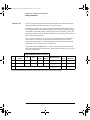
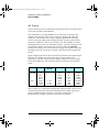
Understanding the “ % of reading ” Error The reading error
compensates for inaccuracies that result from the function and range you
select, as well as the input signal level. The reading error varies
according to the input level on the selected range. This error is expressed
in percent of reading. The following table shows the reading error
applied to the internal DMM’s 24-hour DC voltage specification. .
Range
Input Level
Reading Error
(% of reading)
Reading Error
Voltage
10 VDC
10 VDC
10 VDC
10 VDC
1 VDC
0.1 VDC
0.0015
0.0015
0.0015
150 V
15 V
1.5 V
34
34970A Refresh SG.book Page 35 Thursday, February 4, 2010 11:16 AM
Chapter 1 Specifications
To Calculate Total Measurement Error
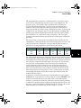
Understanding the “ % of range ” Error The range error
compensates for inaccuracies that result from the function and range you
select. The range error contributes a constant error, expressed as a
percent of range, independent of the input signal level. The following
table shows the range error applied to the DMM’s 24-hour DC voltage
specification.
Range
Input Level
Reading Error
(% of reading)
Range
Error Voltage
10 VDC
10 VDC
10 VDC
10 VDC
1 VDC
0.1 VDC
0.0004
0.0004
0.0004
40 V
40 V
40 V
4
Total Measurement Error To compute the total measurement error,
add the reading error and range error. You can then convert the total
measurement error to a “percent of input” error or a “ppm
(part-per-million) of input” error as shown below.
% of input error = Total Measurement Error
x 100
Input Signal Level
ppm of input error = Total Measurement Error
Input Signal Level
x 1,000,000
Example: Computing Total Measurement Error
Assume that a 5 VDC signal is input to the DMM on the 10 VDC range.
Compute the total measurement error using the 90-day accuracy
specification of ±(0.0020% of reading + 0.0005% of range).
Reading Error
= 0.0020% x 5 VDC
= 100 V
Range Error
= 0.0005% x 10 VDC
= 50 V
Total Error
= 100 V + 50 V
=
±150 V
= ±0.0030% pf 5 VDC
= ±30 ppm of 5 VDC
35
1
34970A Refresh SG.book Page 36 Thursday, February 4, 2010 11:16 AM
Chapter 1 Specifications
Interpreting Internal DMM Specifications
Interpreting Internal DMM Specifications
This section is provided to give you a better understanding of the
terminology used and will help you interpret the internal DMM’s
specifications.
Number of Digits and Overrange
The “number of digits” specification is the most fundamental, and
sometimes, the most confusing characteristic of a multimeter. The
number of digits is equal to the maximum number of “9’s” the multimeter
can measure or display. This indicates the number of full digits. Most
multimeters have the ability to overrange and add a partial or “½” digit.
For example, the internal DMM can measure 9.99999 VDC on the 10 V
range. This represents six full digits of resolution. The internal DMM
can also overrange on the 10 V range and measure up to a maximum of
12.00000 VDC. This corresponds to a 6½-digit measurement with 20%
overrange capability.
Sensitivity
Sensitivity is the minimum level that the internal DMM can detect for a
given measurement. Sensitivity defines the ability of the internal DMM
to respond to small changes in the input level. For example, suppose you
are monitoring a 1 mVDC signal and you want to adjust the level to
within ±1 µV. To be able to respond to an adjustment this small, this
measurement would require a multimeter with a sensitivity of at least 1
µV. You could use a 6½-digit multimeter if it has a 1 VDC or smaller
range. You could also use a 4½-digit multimeter with a 10 mVDC range.
For AC voltage and AC current measurements, note that the smallest
value that can be measured is different from the sensitivity. For the
internal DMM, these functions are specified to measure down to 1% of
the selected range. For example, the internal DMM can measure down to
1 mV on the 100 mV range.
36
34970A Refresh SG.book Page 37 Thursday, February 4, 2010 11:16 AM
Chapter 1 Specifications
Interpreting Internal DMM Specifications
Resolution
Resolution is the numeric ratio of the maximum displayed value divided
by the minimum displayed value on a selected range. Resolution is often
expressed in percent, parts-per-million (ppm), counts, or bits. For
example, a 6½-digit multimeter with 20% overrange capability can
display a measurement with up to 1,200,000 counts of resolution. This
corresponds to about 0.0001% (1 ppm) of full scale, or 21 bits including
the sign bit. All four specifications are equivalent.
4
Accuracy
Accuracy is a measure of the “exactness” to which the internal DMM’s
measurement uncertainty can be determined relative to the calibration
reference used. Absolute accuracy includes the internal DMM’s relative
accuracy specification plus the known error of the calibration reference
relative to national standards (such as the U.S. National Institute of
Standards and Technology). To be meaningful, the accuracy
specifications must be accompanied with the conditions under which
they are valid. These conditions should include temperature, humidity,
and time.
There is no standard convention among instrument manufacturers for
the confidence limits at which specifications are set. The table below
shows the probability of non-conformance for each specification with the
given assumptions.
Specification
Criteria
Probability
of Failure
Mean ±2 sigma
Mean ±3 sigma
4.5%
0.3%
Variations in performance from reading to reading, and instrument to
instrument, decrease for increasing number of sigma for a given
specification. This means that you can achieve greater actual
measurement precision for a specific accuracy specification number. The
34970A/34972A is designed and tested to meet performance better than
mean ±3 sigma of the published accuracy specifications.
37
1
34970A Refresh SG.book Page 38 Thursday, February 4, 2010 11:16 AM
Chapter 1 Specifications
Interpreting Internal DMM Specifications
24-Hour Accuracy
The 24-hour accuracy specification indicates the internal DMM’s relative
accuracy over its full measurement range for short time intervals and
within a stable environment. Short-term accuracy is usually specified for
a 24-hour period and for a ±1 °C temperature range.
90-Day and 1-Year Accuracy
These long-term accuracy specifications are valid for a 23 °C ± 5 °C
temperature range. These specifications include the initial calibration
errors plus the internal DMM’s long-term drift errors.
Temperature Coefficients
Accuracy is usually specified for a 23 °C ± 5 °C temperature range. This
is a common temperature range for many operating environments. You
must add additional temperature coefficient errors to the accuracy
specification if you are operating the internal DMM outside a 23 °C ± 5
°C temperature range (the specification is per °C).
38
34970A Refresh SG.book Page 39 Thursday, February 4, 2010 11:16 AM
Chapter 1 Specifications
Configuring for Highest Accuracy Measurements
Configuring for Highest Accuracy Measurements
The measurement configurations shown below assume that the internal
DMM is in its Factory Reset state. It is also assumed that manual
ranging is enabled to ensure proper full scale range selection.
DC Voltage, DC Current, and Resistance Measurements:
4
• Set the resolution to 6 digits (you can use the 6 digits slow mode for
further noise reduction).
• Set the input resistance to greater than 10 G (for the 100 mV, 1 V,
and 10 V ranges) for the best DC voltage accuracy.
• Use 4-wire ohms and enable offset compensation for the best
resistance accuracy.
AC Voltage and AC Current Measurements:
• Set the resolution to 6 digits.
• Select the slow AC filter (3 Hz to 300 kHz).
Frequency and Period Measurements:
• Set the resolution to 6 digits.
39
1
34970A Refresh SG.book Page 40 Thursday, February 4, 2010 11:16 AM
Chapter 1 Specifications
Configuring for Highest Accuracy Measurements
40
34970A Refresh SG.book Page 41 Thursday, February 4, 2010 11:16 AM
2
2
Quick Start
34970A Refresh SG.book Page 42 Thursday, February 4, 2010 11:16 AM
Quick Start
One of the first things to do with your instrument is to become
acquainted with the front panel. We have written the exercises in this
chapter to prepare the instrument for use and help you get familiar with
some of its front-panel operations.
The front panel has several groups of keys to select various functions and
operations. A few keys have a shifted function printed in blue below the
key. To perform a shifted function, press
(the SHIFT annunciator
will turn on). Then, press the key that has the desired label below it. For
example, to select the Utility Menu, press
.
If you accidentally press
annunciator.
, just press it again to turn off the SHIFT
This chapter is divided into the following sections:
• To Prepare the Instrument for Use, on page 43
• To Connect Wiring to a Module, on page 44
• To Set the Time and Date, on page 46
• To Configure a Measurement Channel, on page 47
• To Monitor a Single Channel, on page 48
• To Close a Channel, on page 49
• If the Instrument Does Not Turn On, on page 50
• To Adjust the Carrying Handle, on page 52
• To Rack Mount the Instrument, on page 53
42
34970A Refresh SG.book Page 43 Thursday, February 4, 2010 11:16 AM
Chapter 2 Quick Start
To Prepare the Instrument for Use
To Prepare the Instrument for Use
1 Check the list of supplied items.
2
Verify that you have received the following items with your instrument.
If anything is missing, contact your nearest Agilent Technologies Sales
Office.
• One power cord.
4
• One User’s Guide.
• This Service Guide.
• One Quick Reference Guide.
• Certificate of Calibration (if you ordered the internal DMM).
• BenchLink Data Logger 3 Software CD-ROM.
• Quick Start Package (if you ordered the internal DMM):
• One RS-232 cable.
• One J-type thermocouple and a flatblade screwdriver.
• Any plug-in modules that you ordered are delivered in a separate
shipping container.
On/Standby
Switch
WARNING
Note that this switch
is Standby only.
To disconnect the
mains from the
instrument, remove
the power cord.
2 Verify that the fuse on the back is set to the proper voltage range
for your AC power.
3 Connect the power cord and turn on the instrument.
The front-panel display will light up briefly while the instrument
performs its power-on self-test. The instrument initially powers up with
all measurement channels turned off. To review the power-on display
as you turn on the
with all annunciators turned on, hold down
instrument. If the instrument does not turn on properly, see page 50.
4 Perform a complete self-test.
The complete self-test performs a more extensive set of tests than those
performed at power-on. Hold down
as you turn on the instrument
and hold down the key until you hear a long beep. The self-test will begin
when you release the key following the beep.
43
34970A Refresh SG.book Page 44 Thursday, February 4, 2010 11:16 AM
Chapter 2 Quick Start
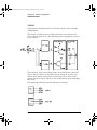
To Connect Wiring to a Module
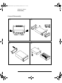
To Connect Wiring to a Module
1. Remove the module cover.
2 Connect wiring to the screw terminals.
20 AWG Typical
6 mm
3 Route wiring through strain relief.
4 Replace the module cover.
Cable Tie Wrap
(optional)
5 Install the module into mainframe.
Channel Number:
Slot Channel
44
Wiring Hints...
• For detailed information on each module, refer
to the 34970A/34972A User’s Guide.
• To reduce wear on the internal DMM relays,
wire like functions on adjacent channels.
• Use shielded twisted pair PTFE insulated
cables to reduce settling and noise errors.
• The diagrams on the next page show how to
connect wiring to a multiplexer module for each
measurement function.
34970A Refresh SG.book Page 45 Thursday, February 4, 2010 11:16 AM
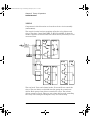
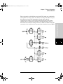
Chapter 2 Quick Start
To Connect Wiring to a Module
Thermocouple
DC Voltage / AC Voltage / Frequency
2
4
Thermocouple Types: B, E, J, K, N, R, S, T
See the 34970A/34972A User’s Guide for
thermocouple color codes.
2-Wire Ohms / RTD / Thermistor
Ranges: 100 mV, 1 V, 10 V, 100 V, 300 V
4-Wire Ohms / RTD
Ranges: 100, 1 k, 10 k, 100 k, 1 M, 10 M, 100 M
RTD Types: 0.00385, 0.00391
Thermistor Types, 2.2 k, 5 k, 10 k
DC Current / AC Current
Channel n (source) is automatically paired with
Channel n +10 (sense) on the 34901A, or
Channel n +8 (sense) on the 34902A.
Valid only on channels 21 and 22 on the 34901A
Ranges: 10 mA, 100 mA, 1A
Ranges: 100, 1 k, 10 k, 100 k, 1 M, 10 M, 100 M
RTD Types: 0.00385, 0.00391
45
34970A Refresh SG.book Page 46 Thursday, February 4, 2010 11:16 AM
Chapter 2 Quick Start
To Set the Time and Date
To Set the Time and Date
All readings during a scan are automatically time stamped and stored in
non-volatile memory. In addition, alarm data is time stamped and stored
in a separate non-volatile memory queue.
1 Set the time of day.
Use
and
to select the field to modify and turn the knob to change
the value. You can also edit the AM/PM field.
TIME 03:45 PM
2 Set the date.
Use
and
the value.
JUN 01 2002
46
to select the field to modify and turn the knob to change
34970A Refresh SG.book Page 47 Thursday, February 4, 2010 11:16 AM
Chapter 2 Quick Start
To Configure a Measurement Channel
To Configure a Measurement Channel
Use this general procedure to configure a measurement channel.
2
1 Select the channel.
Turn the knob until the desired channel is shown on the right side of
front-panel display. The channel number is a three-digit number; the 4
left-most digit represents the slot number (100, 200, or 300) and the two
digits on the right indicate the channel number (102, 110, etc.).
Note: You can use
next slot.
and
to skip to the beginning of the previous or
2 Select the measurement parameters for the selected channel.
Use the knob to scroll through the measurement choices on each level of
the menu. When you press
to make your selection, the menu
automatically guides you through all relevant choices to configure a
measurement on the selected function. When you have finished
configuring the parameters, you are automatically exited from the menu.
The present selection (or default) is displayed in full bright for easy
identification. When you make a different selection, the new choice is
shown in full bright and it becomes the default selection. The order of the
choices always remains the same; however, you always enter the menu
at the current (full bright) setting for each parameter.
Note: The menu will time-out after about 20 seconds of inactivity and any
changes made previously will take effect.
47
34970A Refresh SG.book Page 48 Thursday, February 4, 2010 11:16 AM
Chapter 2 Quick Start
To Monitor a Single Channel
To Monitor a Single Channel
You can use the Monitor function to continuously take readings on a
single channel, even during a scan. This feature is used during front
panel calibration procedures.
1 Select the channel to be monitored.
Only one channel can be monitored at a time but you can change the
channel being monitored at any time by turning the knob.
2 Enable monitoring on the selected channel.
Any channel that can be “read” by the instrument can be monitored (the
MON annunciator turns on). This includes any combination of
temperature, voltage, resistance, current, frequency, or period
measurements on multiplexer channels. You can also monitor a digital
input port or the totalizer count on the multifunction module.
To disable monitoring, press
48
again.
34970A Refresh SG.book Page 49 Thursday, February 4, 2010 11:16 AM
Chapter 2 Quick Start
To Close a Channel
To Close a Channel
On the multiplexer and switch modules, you can close and open
individual relays on the module. However, note that if you have already
configured any multiplexer channels for scanning, you cannot
independently close and open individual relays on that module.
4
1 Select the channel.
Turn the knob until the desired channel is shown on the right side of
front-panel display. For this example, select channel 213.
2 Close the selected channel.
3 Open the selected channel.
Note:
will sequentially open all channels on the module in the
selected slot.
The table below shows the low-level control operations available for each
of the plug-in modules.
Plug-In Module
,
34901A 20-Channel Mux
34902A 16-Channel Mux
34908A 40-Channel Single-Ended Mux [1]
34903A 20-Channel Actuator
34904A 4x8 Matrix
[2]
34906A Dual 4-Channel RF Mux (75)[2]
34905A Dual 4-Channel RF Mux (50)
34907A Multifunction Module (DIO)
34907A Multifunction Module (Totalizer)
34907A multifunction Module (DAC)
[1] Only one channel can be closed at a time on this module.
[2] Only one channel in each bank can be closed at a time on this module.
49
2
34970A Refresh SG.book Page 50 Thursday, February 4, 2010 11:16 AM
Chapter 2 Quick Start
If the Instrument Does Not Turn On
If the Instrument Does Not Turn On
Use the following steps to help solve problems you might encounter when
turning on the instrument.
1 Verify that there is AC power to the instrument.
First, verify that the power cord is firmly plugged into the power
receptacle on the rear panel of the instrument. You should also make
sure that the power source you plugged the instrument into is energized.
Then, verify that the instrument is turned on.
The On/Standby switch
panel.
is located on the lower left side of the front
2 Verify the power-line voltage setting.
The line voltage is set to the proper value for your country when the
instrument is shipped from the factory. Change the voltage setting if it is
not correct. The settings are: 100, 120, 220, or 240 VAC.
Note: For 127 VAC operation, use the 120 VAC setting.
For 230 VAC operation, use the 220 VAC setting.
See the next page if you need to change the line voltage setting.
3 Verify that the power-line fuse is good.
The instrument is shipped from the factory with a 500 mA fuse installed.
This is the correct fuse for all line voltages.
See the next page if you need to replace the power-line fuse.
To replace the 500 mAT, 250 V fuse, order Agilent part number 2110-0458.
50
34970A Refresh SG.book Page 51 Thursday, February 4, 2010 11:16 AM
Chapter 2 Quick Start
If the Instrument Does Not Turn On
1 Remove the power cord. Remove the
fuse-holder assembly from the rear panel.
2 Remove the line voltage selector from the
assembly.
2
4
Fuse: 500 mAT (for all line voltages)
Agilent Part Number: 2110-0458
3 Rotate the line-voltage selector until the
correct voltage appears in the window.
4 Replace the fuse-holder assembly in the
rear panel.
100, 120 (127), 220 (230), or 240 VAC
Verify that the correct line voltage is selected and the power-line fuse is good.
51
34970A Refresh SG.book Page 52 Thursday, February 4, 2010 11:16 AM
Chapter 2 Quick Start
To Adjust the Carrying Handle
To Adjust the Carrying Handle
To adjust the position, grasp the handle by the sides and pull outward.
Then, rotate the handle to the desired position.
Bench-top viewing position
52
Carrying position
34970A Refresh SG.book Page 53 Thursday, February 4, 2010 11:16 AM
Chapter 2 Quick Start
To Rack Mount the Instrument
To Rack Mount the Instrument
You can mount the instrument in a standard 19-inch rack cabinet using
one of three optional kits available. Instructions and mounting hardware
are included with each rack-mounting kit. Any Agilent System II
instrument of the same size can be rack-mounted beside the 34970A/
34972A.
Note: Remove the carrying handle, and the front and rear rubber
bumpers, before rack-mounting the instrument.
4
To remove the handle, rotate it to the vertical position and pull the ends outward.
Front
Rear (bottom view)
To remove the rubber bumper, stretch a corner and then slide it off.
53
2
34970A Refresh SG.book Page 54 Thursday, February 4, 2010 11:16 AM
Chapter 2 Quick Start
To Rack Mount the Instrument
To rack mount a single instrument, order adapter kit 5063-9240.
To rack mount two instruments side-by-side, order lock-link kit 5061-9694 and
flange kit 5063-9212. Be sure to use the support rails inside the rack cabinet.
To install one or two instruments in a sliding support shelf, order shelf 5063-9255,
and slide kit 1494-0015 (for a single instrument, also order filler panel 5002-3999).
54
34970A Refresh SG.book Page 55 Thursday, February 4, 2010 11:16 AM
3
3
Front-Panel Overview
34970A Refresh SG.book Page 56 Thursday, February 4, 2010 11:16 AM
Front-Panel Overview
This chapter introduces you to the front-panel keys and menu operation.
This chapter does not give a detailed description of every front-panel key
or menu operation. It does, however, give you an overview of the frontpanel menus and many front-panel operations. See the Agilent 34970A/
34972A User’s Guide for a complete discussion of the instrument’s
capabilities and operation.
This chapter is divided into the following sections:
• Front-Panel Menu Reference, on page 57
• To Unsecure for Calibration, on page 60
• To Secure Against Calibration, on page 61
• To Change the Security Code, on page 62
• Error Messages, on page 62
• To Perform a Zero Adjustment, on page 63
• To Apply Mx+B Scaling to Measurements, on page 64
• To Read the Relay Cycle Count, on page 65
• To Read a Digital Input Port, on page 66
• To Write to a Digital Output Port, on page 67
• To Read the Totalizer Count, on page 68
• To Output a DC Voltage, on page 69
56
34970A Refresh SG.book Page 57 Thursday, February 4, 2010 11:16 AM
Chapter 3 Front-Panel Overview
Front-Panel Menu Reference
Front-Panel Menu Reference
This section gives an overview of the front-panel menus. The menus are
designed to automatically guide you through all parameters required to
configure a particular function or operation. The remainder of this
chapter contains examples of using the front-panel menus.
Configure the measurement parameters on the displayed channel.
•
•
•
•
•
•
4
Select the measurement function (dc volts, ohms, etc.) on the displayed channel.
Select transducer type for temperature measurements.
Select units (°C, °F, or K) for temperature measurements.
Select measurement range or autorange.
Select measurement resolution.
Copy and paste measurement configuration to other channels.
Configure the scaling parameters for the displayed channel.
• Set the gain (“M”) and offset (“B”) value for the displayed channel.
• Make a null measurement and store it as the offset value.
• Specify a custom label (RPM, PSI, etc.) for the displayed channel.
Configure alarms on the displayed channel.
• Select one of four alarms to report alarm conditions on the displayed channel.
• Configure a high limit, low limit, or both for the displayed channel.
• Configure a bit pattern that will generate an alarm (digital input only).
Configure the four Alarm Output hardware lines.
• Clear the state of the four alarm output lines.
• Select the “Latch” or “Track” mode for the four alarm output lines.
• Select the slope (rising or falling edge) for the four alarm output lines.
Configure the event or action that controls the scan interval.
• Select the scan interval mode (interval, manual, external, or alarm).
• Select the scan count.
57
3
34970A Refresh SG.book Page 58 Thursday, February 4, 2010 11:16 AM
Chapter 3 Front-Panel Overview
Front-Panel Menu Reference
Configure the advanced measurement features on displayed channel.
•
•
•
•
•
•
•
•
•
Set the integration time for measurements on the displayed channel.
Set the channel-to-channel delay for scanning.
Enable/disable the thermocouple check feature (T/C measurements only).
Select the reference junction source (T/C measurements only).
Set the low frequency limit (ac measurements only).
Enable/disable offset compensation (resistance measurements only).
Select the binary or decimal mode for digital operations (34907A only).
Configure the totalizer reset mode (totalizer only).
Select which edge is detected (rising or falling) for totalizer operations.
Configure system-related instrument parameters.
•
•
•
•
•
Set the real-time system clock and calendar.
Query the firmware revisions for the mainframe and installed modules.
Select the instrument’s power-on configuration (last or factory reset).
Enable/disable the internal DMM.
Secure/unsecure the instrument for calibration.
View readings, alarms, and errors.
•
•
•
•
View the last 100 scanned readings from memory (last, min, max, and average).
View the first 20 alarms in the alarm queue (reading and time alarm occurred).
View up to 10 errors (34970A) or 20 errors (34972A) in the error queue.
Read the number of cycles for the displayed relay (relay maintenance feature).
Store and recall instrument states.
• Store up to five instrument states in non-volatile memory.
• Assign a name to each storage location.
• Recall stored states, power-down state, factory reset state, or preset state.
58
34970A Refresh SG.book Page 59 Thursday, February 4, 2010 11:16 AM
Chapter 3 Front-Panel Overview
Front-Panel Menu Reference
Configure the remote interface (34970A).
• Select the GPIB address.
• Configure the RS-232 interface (baud rate, parity, and flow control).
Configure the remote interface (34972A).
4
• Configure the LAN settings (IP Address, Hostname, DHCP, etc.)
• Configure the USB settings (Enable, USB ID, etc.)
• Configure and use the USB drive (Logging, etc.)
59
3
34970A Refresh SG.book Page 60 Thursday, February 4, 2010 11:16 AM
Chapter 3 Front-Panel Overview
To Unsecure for Calibration
To Unsecure for Calibration
You can unsecure the instrument either from the front panel or over the
remote interface. The instrument is secured when shipped from the
factory and the security code is set to “HP034970” or “AT034972”,
depending on the product number.
• Once you enter a security code, that code must be used for both frontpanel and remote operation. For example if you secure the
instrument from the front panel, you must use that same code to
unsecure it from the remote interface.
• Press
to enter the Utility menu.
When you first enter the Utility menu, the calibration entries toggle
between CAL SECURED and UNSECURE CAL. To unsecure the
instrument, select UNSECURE CAL and press
. After entering the
again. When you return to the menu,
correct security code, press
you will see new choices CAL UNSECURED and SECURE CAL.
Note: If you enter the wrong secure code, NO MATCH is displayed and a
new choice, EXIT, is shown.
60
34970A Refresh SG.book Page 61 Thursday, February 4, 2010 11:16 AM
Chapter 3 Front-Panel Overview
To Secure Against Calibration
To Secure Against Calibration
You can secure the instrument either from the front panel or over the
remote interface. The instrument is secured when shipped from the
factory and the security code is set to “HP034970” or “AT034972”,
depending on the product number.
• Once you enter a security code, that code must be used for both front4
panel and remote operation. For example if you secure the
instrument from the front panel, you must use that same code to
unsecure it from the remote interface.
• Press
to enter the Utility menu.
When you enter the Utility menu, the calibration entries toggle between
CAL UNSECURED and SECURE CAL. To secure the instrument, select
SECURE CAL and press
. After entering the desired security code,
again. When you return to the menu, you will see new choices
press
CAL SECURED and UNSECURE CAL.
61
3
34970A Refresh SG.book Page 62 Thursday, February 4, 2010 11:16 AM
Chapter 3 Front-Panel Overview
To Change the Security Code
To Change the Security Code
• To change the security code, you must first unsecure the instrument,
and then enter a new code. Make sure you have read the security code
rules described on page 77 before attempting to change the security
code.
• To change the security code, first make sure that the instrument is
unsecured. Go to the SECURE CAL entry, enter the new security
(the instrument is now secured with the new code).
code, and press
Changing the code from the front panel also changes the code as seen
from the remote interface.
Error Messages
Error messages are retrieved in a first-in-first-out (FIFO) order.
When the ERROR annunciator is on, press
to view error messages.
use the arrow keys to scroll the message in the display.
A list of the self-test errors messages and their meanings begins on page
178.
For a complete list of error messages and descriptions, see chapter 6 in
the 34970A/34972A User’s Guide.
62
34970A Refresh SG.book Page 63 Thursday, February 4, 2010 11:16 AM
Chapter 3 Front-Panel Overview
To Perform a Zero Adjustment
To Perform a Zero Adjustment
The instrument features closed case electronic calibration. No internal
mechanical adjustments are required. The instrument calculates
correction factors based upon an input reference value and stores the
correction factors in non-volatile memory. This procedure demonstrates
making the zero adjustment from the front panel. The gain adjustments
4
are similar.
DO NOT perform this procedure before reading Chapter 4. Chapter 4
describes this procedure, the required input connections, input signals,
and test considerations required for a valid adjustment.
1 Configure the channel.
You must configure a channel before applying performing the
adjustment procedure. Configure the channel to DC VOLTS and 6½
digits.
2 Apply the input signal
In this example, the input signal is a copper short (see page 76).
3 Setup the calibration.
The display will show PERFORM CAL.
4 Set the adjustment value.
The display will show the a number. Edit the number to the actual input
value. For the Zero Adjustment, the input value is 0.000000.
+000.000,000 mVDC
5 Begin the adjustment.
The display will show the progress of the adjustment. When all the
adjustments are completed, the display will show done.
DONE
63
3
34970A Refresh SG.book Page 64 Thursday, February 4, 2010 11:16 AM
Chapter 3 Front-Panel Overview
To Apply Mx+B Scaling to Measurements
To Apply Mx+B Scaling to Measurements
The scaling function allows you to apply a gain and offset to all readings
on a specified multiplexer channel during a scan. In addition to setting
the gain (“M”) and offset (“B”) values, you can also specify a custom
measurement label for your scaled readings (RPM, PSI, etc.).
1 Configure the channel.
You must configure the channel (function, transducer type, etc.) before
applying any scaling values. If you change the measurement
configuration, scaling is turned off on that channel and the gain and
offset values are reset (M=1 and B=0).
2 Set the gain and offset values.
The scaling values are stored in non-volatile memory for the specified
channels. A Factory Reset turns off scaling and clears the scaling values
on all channels. An Instrument Preset or Card Reset does not clear the
scaling values and does not turn off scaling.
+1.000,000
Set Gain
-0.700,000 OHM
Set Offset
3 Select the custom label.
You can specify an optional three-character label for your scaled
readings (RPM, PSI, etc.). The default label is the standard engineering
unit for the selected function (VDC, OHM, etc.).
LABEL AS OHM
4 Scaling is now applied to the measurements.
64
34970A Refresh SG.book Page 65 Thursday, February 4, 2010 11:16 AM
Chapter 3 Front-Panel Overview
To Read the Relay Cycle Count
To Read the Relay Cycle Count
The instrument has a Relay Maintenance System to help you predict
relay end-of-life. The instrument counts the cycles on each relay in the
instrument and stores the total count in non-volatile memory on each
switch module. You can use this feature on any of the relay modules and
the internal DMM.
4
• In addition to the channel relays, you can also query the count on
backplane relays and bank relays. Note that you cannot control the
state of these relays from the front panel but you can query the count.
• You can also query the state of the three relays on the internal DMM.
These relays are numbered “1”, “2”, and “3” (which correspond to
relays K102, K103, and K104 respectively). These relays open or close
when a function or range is changed on a module.
• The 34908A multiplexer contains 40 channels which are switched (HI
only) using only 20 relays. Each relay is used to switch HI on two
different channels (and only one channel can be closed at a time). The
channels are arranged such that channels 01 and 21 use different
contacts on the same relay. The remaining channels are also paired in
the same manner (channels 02 and 22, channels 03 and 23, etc.).
Therefore, when you query the relay count on a channel, the number
reflects the number of times that the relay was closed. For example,
the relay count will always be the same on channels 01 and 21.
• For more information on relay life and load considerations, refer to
“Relay Life and Preventative Maintenance” in the 34970A/34972A
User’s Guide.
• To read the count on the active channel, choose the following item
and then turn the knob. To read the count on the internal DMM
relays, turn the knob counterclockwise beyond the lowest numbered
channel in the instrument. To read the “hidden” relays, turn the knob
clockwise beyond the highest numbered channel in the current slot.
RELAY CYCLES
65
3
34970A Refresh SG.book Page 66 Thursday, February 4, 2010 11:16 AM
Chapter 3 Front-Panel Overview
To Read a Digital Input Port
To Read a Digital Input Port
The multifunction module (34907A) has two non-isolated 8-bit input/
output ports which you can use for reading digital patterns. You can read
the live status of the bits on the port or you can configure a scan to
include a digital read.
1 Select the Digital Input port.
Select the slot containing the multifunction module and continue turning
the knob until DIN is displayed (channel 01 or 02).
2 Read the specified port.
You can specify whether you want to use binary or decimal format. Once
you have selected the number base, it is used for all input or output
operations on the same port. To change the number base, press the
key and select USE BINARY or USE DECIMAL.
.
01010101 DIN
Binary Display Shown
The bit pattern read from the port will be displayed until you press
another key, turn the knob, or until the display times out.
Note: To add a digital input channel to a scan list, press
the DIO READ choice.
66
and select
34970A Refresh SG.book Page 67 Thursday, February 4, 2010 11:16 AM
Chapter 3 Front-Panel Overview
To Write to a Digital Output Port
To Write to a Digital Output Port
The multifunction module (34907A) has two non-isolated 8-bit
input/output ports which you can use for outputting digital patterns.
1 Select the Digital Output port.
Select the slot containing the multifunction module and continue turning
4
the knob until DIN is displayed (channel 01 or 02).
2 Enter the bit pattern editor.
Notice that the port is now converted to an output port (DOUT).
.
00000000 DOUT
Binary Display Shown
3 Edit the bit pattern.
Use the knob and
or
keys to edit the individual bit values. You
can specify whether you want to use binary or decimal format. Once you
have selected the number base, it is used for all input or output
operations on the same port. To change the number base, press the
key and select USE BINARY or USE DECIMAL.
.
240 DOUT
Decimal Display Shown
4 Output the bit pattern to the specified port.
The specified bit pattern is latched on the specified port. To cancel an
output operation in progress, wait for the display to time out.
67
3
34970A Refresh SG.book Page 68 Thursday, February 4, 2010 11:16 AM
Chapter 3 Front-Panel Overview
To Read the Totalizer Count
To Read the Totalizer Count
The multifunction module (34907A) has a 26-bit totalizer which can
count pulses at a 100 kHz rate. You can manually read the totalizer
count or you can configure a scan to read the count.
1 Select the totalizer channel.
Select the slot containing the multifunction module and continue turning
the knob until TOTALIZE is displayed (channel 03).
2 Configure the totalize mode.
The internal count starts as soon as you turn on the instrument. You can
configure the totalizer to reset the count to “0” after being read or it can
count continuously and be manually reset.
READ + RESET
3 Read the count.
The count is read once each time you press
; the count does not
update automatically on the display. As configured in this example, the
count is automatically reset to “0” each time you read it.
12345 TOT
The count will be displayed until you press another key, turn the knob,
or until the display times out. To manually reset the totalizer count,
press
.
Note: To add a totalizer channel to a scan list, press
TOT READ choice.
68
and select the
34970A Refresh SG.book Page 69 Thursday, February 4, 2010 11:16 AM
Chapter 3 Front-Panel Overview
To Output a DC Voltage
To Output a DC Voltage
The multifunction module (34907A) has two analog outputs capable of
outputting calibrated voltages between ±12 volts.
1 Select a DAC Output channel.
Select the slot containing the multifunction module and continue turning
4
the knob until DAC is displayed (channel 04 or 05).
2 Enter the output voltage editor.
+00.000 V DAC
3 Set the desired output voltage.
Use the knob and
or
keys to edit the individual digits.
+05.250VDAC
4 Output the voltage from the selected DAC.
The output voltage will be displayed until you press another key or turn
the knob. To manually reset the output voltage to 0 volts, press
.
69
3
34970A Refresh SG.book Page 70 Thursday, February 4, 2010 11:16 AM
Chapter 3 Front-Panel Overview
To Output a DC Voltage
70
34970A Refresh SG.book Page 71 Thursday, February 4, 2010 11:16 AM
4
4
Calibration Procedures
34970A Refresh SG.book Page 72 Thursday, February 4, 2010 11:16 AM
Calibration Procedures
This chapter contains procedures for verification of the instrument’s
performance and adjustment (calibration). These procedures are required
only if the internal DMM is installed. The chapter is divided into the
following sections:
• Agilent Technologies Calibration Services, on page 73
• Calibration Interval, on page 73
• Time Required for Calibration, on page 74
• Automating Calibration Procedures, on page 74
• Recommended Test Equipment, on page 75
• Input Connections, on page 76
• Calibration Security, on page 77
• Calibration Message, on page 79
• Calibration Count, on page 79
• Calibration Procedure, on page 80
• Aborting a Calibration in Progress, on page 80
• Test Considerations, on page 81
• Performance Verification Tests, on page 82
• Internal DMM Verification Tests, on page 85
• Optional AC Performance Verification Tests, on page 90
• Internal DMM Adjustments, on page 91
• –10 VDC Adjustment Procedure (Optional), on page 95
• Plug-in Module Test Considerations, on page 97
• Relay Verification, on page 98
• Thermocouple Reference Junction (Optional), on page 122
• 34907A Analog Output, on page 124
Closed-Case Electronic Calibration The instrument features closedcase electronic calibration. No internal mechanical adjustments are
required. The instrument calculates correction factors based upon the
input reference value you set. The new correction factors are stored in
non-volatile memory until the next calibration adjustment is performed.
Non-volatile EEPROM calibration memory does not change when power
has been off or after a remote interface reset.
72
34970A Refresh SG.book Page 73 Thursday, February 4, 2010 11:16 AM
Chapter 4 Calibration Procedures
Agilent Technologies Calibration Services
Agilent Technologies Calibration Services
When your instrument is due for calibration, contact your local Agilent
Service Center for a low-cost recalibration. The 34970A/34972A is
supported on automated calibration systems which allow Agilent to
provide this service at competitive prices.
Calibration Interval
The instrument should be calibrated on a regular interval determined by
the measurement accuracy requirements of your application.
A 1-year interval is adequate for most applications. Accuracy
specifications are warranted only if adjustment is made at regular
calibration intervals. Accuracy specifications are not warranted beyond
the 1-year calibration interval. Agilent does not recommend extending
calibration intervals beyond 2 years for any application.
Adjustment is Recommended
Whatever calibration interval you select, Agilent recommends that
complete re-adjustment should always be performed at the calibration
interval. This will assure that the 34970A/34972A will remain within
specification for the next calibration interval. This criteria for readjustment provides the best long-term stability. Performance data
measured using this method can be used to extend future calibration
intervals.
Use the Calibration Count feature (see page 79) to verify that all
adjustments have been performed.
73
4
34970A Refresh SG.book Page 74 Thursday, February 4, 2010 11:16 AM
Chapter 4 Calibration Procedures
Time Required for Calibration
Time Required for Calibration
The 34970A/34972A can be automatically calibrated under computer
control. With computer control you can perform the complete calibration
procedure and performance verification tests in less than 30 minutes
once the instrument is warmed-up (see “Test Considerations” on page 81).
Manual calibrations using the recommended test equipment will take
approximately 2 hours.
Automating Calibration Procedures
You can automate the complete verification and adjustment procedures
outlined in this chapter if you have access to programmable test
equipment. You can program the instrument configurations specified for
each test over the remote interface. You can then enter readback
verification data into a test program and compare the results to the
appropriate test limit values.
You can also adjust the instrument from the remote interface. Remote
adjustment is similar to the local front-panel procedure. You can use a
computer to perform the adjustment by first selecting the required
function and range. The calibration value is sent to the instrument and
then the calibration is initiated over the remote interface. The
instrument must be unsecured prior to initiating the calibration
procedure.
For further information on programming the instrument, see chapter 5
in the 34970A/34972A User’s Guide.
74
34970A Refresh SG.book Page 75 Thursday, February 4, 2010 11:16 AM
Chapter 4 Calibration Procedures
Recommended Test Equipment
Recommended Test Equipment
The test equipment recommended for the performance verification and
adjustment procedures is listed below. If the exact instrument is not
available, substitute calibration standards of equivalent accuracy.
A suggested alternate method would be to use the Agilent 3458A
8½-digit Digital Multimeter to measure less accurate yet stable sources.
The output value measured from the source can be entered into the
instrument as the target calibration value.
Application
Calibration[1]
Recommended Equipment
4
Accuracy Requirements
Zero
DC Voltage[1]
Dc Current[1]
Resistance[1]]
AC Voltage[1]
AC Current[1]
Frequency[1]
None
Fluke 5700A
Fluke 5700A/5725A
Fluke 5700A
Fluke 5700A/5725A
Fluke 5700A/5725A
Agilent 33220A
4 -terminal all copper short
<1/5 instrument 24 hour spec
<1/5 instrument 24 hour spec
<1/5 instrument 24 hour spec
<1/5 instrument 24 hour spec
<1/5 instrument 24 hour spec
<1/5 instrument 24 hour spec
Analog Output
34907A
Agilent 34401A
<1/5 instrument 24 hour spec
Thermocouple
Reference Junction
34901A
34902A
34908A
Thermistor YSI 44031 (two) [2]
±0.1 °C
Relay contact resistance
All switch modules
Agilent 34401A
J Type Calibrated Thermocouple
Triple Point Cell
±0.001 resolution
[1] In addition to the internal DMM, these applications require an input multiplexer module. The
Agilent 34901A is recommended.
[2] Thermistor YSI 44031 is available as Agilent part number 34308A (package of five).
75
34970A Refresh SG.book Page 76 Thursday, February 4, 2010 11:16 AM
Chapter 4 Calibration Procedures
Input Connections
Input Connections
You will need an input multiplexer module to verify or adjust the
internal DMM. Input connections can be made using a 34901A
20-Channel Multiplexer.
To use a 34901A to completely verify and adjust the internal DMM,
make the following connections:
Connections for
DC/AC Current
Connections for
4-wire Ohms
Connections for DC V, AC V,
2- and 4-wire Ohms
Copper Short
34901A
To
Calibrator
Note: Use shielded twisted pair PTFE insulated cables to reduce
settling and noise errors. Connect the shield to the source LO output.
You can also use a 34902A for test and adjustment of voltage, frequency,
and resistance functions. You cannot test or adjust current inputs with a
34902A. If you use a 34902A, connect the copper shorts to Channels 7
and 15 and make the input connections to Channels 8 and 16.
76
34970A Refresh SG.book Page 77 Thursday, February 4, 2010 11:16 AM
Chapter 4 Calibration Procedures
Calibration Security
Calibration Security
This feature allows you to enter a security code to prevent accidental or
unauthorized adjustments of the instrument. When you first receive
your instrument, it is secured. Before you can adjust the instrument, you
must unsecure it by entering the correct security code. See page 60 in
Chapter 3 for a procedure to enter the security code.
• The security code is set to “HP034970” or “AT034972”, depending on
the product number, when the instrument is shipped from the
factory. The security code is stored in non-volatile memory, and does
not change when power has been off, after a Factory Reset (*RST
command), or after an Instrument Preset (SYSTem:PRESet
command).
• The security code may contain up to 12 alphanumeric characters. The
first character must be a letter, but the remaining characters can be
letters, numbers, or an underscore ( _ ). You do not have to use all 12
characters but the first character must always be a letter.
Note: If you forget your security code, you can disable the security feature
by adding a jumper inside the instrument as described on the following
page.
77
4
34970A Refresh SG.book Page 78 Thursday, February 4, 2010 11:16 AM
Chapter 4 Calibration Procedures
Calibration Security
To Unsecure the Instrument Without the Security Code
To unsecure the instrument without the correct security code, follow the
steps below. A front panel procedure to unsecure the instrument is given
on page 60. See “Electrostatic Discharge (ESD) Precautions” on page 172
before beginning this procedure.
WARNING
SHOCK HAZARD. Only service-trained personnel who are aware
of the hazards involved should remove the instrument covers. The
procedures in this section require that you connect the power cord
to the instrument with the covers removed. To avoid electrical
shock and personal injury, be careful not to touch the power-line
connections.
1 Disconnect the power cord and all input connections.
2 Remove the instrument cover (see page 183). Turn the instrument over.
3 Apply power and turn on the instrument.
WARNING
Be careful not to touch the power line connections.
• Exposed Mains
• Do not Touch! 4 Apply a short between the two exposed metal pads marked
CAL UNLOCK as shown in the figure below.
Apply Short
5 While maintaining the short, enter any unsecure code. The instrument is
now unsecured.
6 Remove the short.
7 Turn off the instrument and remove the power cord. Reassemble the
instrument.
Now you can enter a new security code. Be sure to remember the new
security code.
78
34970A Refresh SG.book Page 79 Thursday, February 4, 2010 11:16 AM
Chapter 4 Calibration Procedures
Calibration Message
Calibration Message
The instrument allows you to store one message in calibration memory.
For example, you can store such information as the date when the last
calibration was performed, the date when the next calibration is due, the
instrument’s serial number, or even the name and phone number of the
person to contact for a new calibration.
• You can record a calibration message only from the remote interface
and only when the instrument is unsecured. You can read the
message from either the front-panel or over the remote interface. You
can read the calibration message whether the instrument is secured
or unsecured.
• The calibration message may contain up to 40 characters. From the
front panel, you can view 13 characters of the message at a time.
Press
to scroll through the text of the message. Press
again to
increase the scrolling speed.
Calibration Count
You can query the instrument to determine how many calibrations have
been performed. Note that your instrument was calibrated before it left
the factory. When you receive your instrument, be sure to read the count
to determine its initial value.
• The calibration count increments up to a maximum of 65,535 after
which it rolls over to “0”. Since the value increments by one for each
calibration point, a complete calibration may increase the value by
many counts.
• The calibration count is also incremented with calibrations of the
DAC channels on the multifunction module.
• Front-Panel Operation:
CAL COUNT
• Remote Interface Operation:
CALibration:COUNt?
79
4
34970A Refresh SG.book Page 80 Thursday, February 4, 2010 11:16 AM
Chapter 4 Calibration Procedures
Calibration Procedure
Calibration Procedure
The following procedure is the recommended method to complete an
instrument calibration.
1 Read “Test Considerations” (page 81).
2 Unsecure the instrument for calibration (page 60).
3 Perform the verification tests to characterize the instrument
(incoming data).
4 Perform the zero adjustment procedures.
5 Perform the gain adjustment procedures. Perform the verification
tests to verify the adjustments (outgoing data).
6 Secure the instrument against calibration.
7 Note the new security code and calibration count in the instrument’s
maintenance records.
Aborting a Calibration in Progress
Sometimes it may be necessary to abort a calibration after the procedure
has already been initiated. You can abort a calibration at any time by
turning off the power. When performing a calibration from the remote
interface, you can abort a calibration by issuing a remote interface device
clear message.
CAUTION
If you abort a calibration in progress when the instrument is attempting
to write new calibration constants to EEPROM, you may lose all
calibration constants for the function. Typically, upon re-applying power,
the instrument will report error 705 Cal:Aborted. You may also generate
errors 740 through 746. If this occurs, you should not use the instrument
until a complete re-adjustment has been performed.
80
34970A Refresh SG.book Page 81 Thursday, February 4, 2010 11:16 AM
Chapter 4 Calibration Procedures
Test Considerations
Test Considerations
To ensure proper instrument operation, verify that you have selected the
correct power line voltage prior to attempting any procedure in this
chapter. See “If the Instrument Does Not Turn On”, on page 50.
Errors may be induced by AC signals present on the input leads during a
self-test. Long test leads can also act as an antenna causing pick-up of
AC signals.
For optimum performance, all procedures should comply with the
following recommendations:
• Assure that the calibration ambient temperature is stable and
between 18 °C and 28 °C. Ideally the calibration should be performed
at 23 °C ±1 °C.
• Assure ambient relative humidity is less than 80%.
• Allow a 2-hour warm-up period with a copper short connected and the
multiplexer module installed before verification or adjustment.The
connections are shown in the figure on page 76.
• Use shielded twisted pair PTFE insulated cables to reduce settling
and noise errors. Keep the input cables as short as possible.
• Connect the input cable shield to the source LO output.Except where
noted in the procedures, connect the calibrator LO source to earth
ground.
Two-wire Ohms measurements are affected by the entire path length,
including the plug-in card trace length and slot trace lengths. On the
34901A, Channel 10 is recommended as the median path length (on the
34902A, use Channel 8) for 2-wire Ohms verification and adjustments.
Install the input multiplexer in slot 200.
Because the instrument is capable of making highly accurate
measurements, you must take special care to ensure that the calibration
standards and test procedures used do not introduce additional errors.
Ideally, the standards used to verify and adjust the instrument should be
an order of magnitude more accurate than each instrument range full
scale error specification.
For the DC voltage, DC current, and resistance gain verification
measurements, you should take care to ensure the calibrator’s “0” output
is correct. If necessary, the measurements can be referenced to the
calibrator’s “0” output using Mx + B scaling (see page 64). You will need
to set the offset for each range of the measuring function being verified.
81
4
34970A Refresh SG.book Page 82 Thursday, February 4, 2010 11:16 AM
Chapter 4 Calibration Procedures
Performance Verification Tests
Performance Verification Tests
Use the Performance verification Tests to verify the measurement
performance of the instrument. The performance verification tests use
the instrument’s specifications listed in chapter 1, “Specifications,”
starting on page 21.
You can perform four different levels of performance verification tests:
Self-Test A series of internal verification tests that give a high
confidence that the instrument is operational.
Quick Verification A combination of the internal self-tests and
selected verification tests.
Performance Verification Tests An extensive set of tests that are
recommended as an acceptance test when you first receive the
instrument or after performing adjustments.
Optional Verification Tests Tests not performed with every
calibration. Perform these tests to verify additional specifications or
functions of the instrument.
82
34970A Refresh SG.book Page 83 Thursday, February 4, 2010 11:16 AM
Chapter 4 Calibration Procedures
Performance Verification Tests
Self-Test
A brief power-on self-test occurs automatically whenever you turn on the
instrument. This limited test assures that the instrument is capable of
operation and also checks the plug-in cards for basic operation.
key as you press the
To perform a complete self-test hold down the
power switch to turn on the instrument; hold down the
key for more
than 5 seconds until the instrument beeps (a complete description of these
tests can be found in chapter 6). The instrument will automatically
perform the complete self-test procedure when you release the key. The
self-test will complete in approximately 20 seconds.
• If the self-test is successful, “PASS” is displayed on the front panel.
• If the self-test fails, “FAIL” is displayed and the ERROR annunciator
turns on. If repair is required, see chapter 6, “Service,” for further
details.
• If all tests pass, you have a high confidence (~90%) that the
instrument is operational.
83
4
34970A Refresh SG.book Page 84 Thursday, February 4, 2010 11:16 AM
Chapter 4 Calibration Procedures
Performance Verification Tests
Quick Performance Check
The quick performance check is a combination of internal self-test and
an abbreviated performance test (specified by the letter Q in the
performance verification tests). This test provides a simple method to
achieve high confidence in the instrument’s ability to functionally
operate and meet specifications. These tests represent the absolute
minimum set of performance checks recommended following any service
activity. Auditing the instrument’s performance for the quick check
points (designated by a Q) verifies performance for “normal” accuracy
drift mechanisms. This test does not check for abnormal component
failures.
To perform the quick performance check, do the following:
• Perform a complete self-test. A procedure is given on page 83.
• Perform only the performance verification tests indicated with the
letter Q.
If the instrument fails the quick performance check, adjustment or
repair is required.
Performance Verification Tests
The performance verification tests are recommended as acceptance tests
when you first receive the instrument. The acceptance test results
should be compared against the 90 day test limits. You should use the
24-hour test limits only for verification within 24 hours after performing
the adjustment procedure. After acceptance, you should repeat the
performance verification tests at every calibration interval.
If the instrument fails performance verification, adjustment or repair is
required.
Adjustment is recommended at every calibration interval. If adjustment
is not made, you must guard band, using no more than 80% of the
specifications listed in Chapter 1, as the verification limits.
84
34970A Refresh SG.book Page 85 Thursday, February 4, 2010 11:16 AM
Chapter 4 Calibration Procedures
Internal DMM Verification Tests
Internal DMM Verification Tests
These procedures use inputs connected to a 34901A 20-Channel
Multiplexer (see page 76) installed in slot 200.
Zero Offset Verification
This procedure is used to check the zero offset performance of the
internal DMM. Verification checks are only performed for those
functions and ranges with unique offset calibration constants.
Measurements are checked for each function and range as described in
the procedure below.
Zero Offset Verification Procedure
4
1 Make sure you have read “Test Considerations” on page 81.
2 This procedure will measure the shorts installed on Channels 209 and
219. Leave the Amps input connections (Channel 221) open.
Continued on next page...
85
34970A Refresh SG.book Page 86 Thursday, February 4, 2010 11:16 AM
Chapter 4 Calibration Procedures
Internal DMM Verification Tests
...Continued from previous page
3 Select each function and range in the order shown in the table below.
Before executing each test, you must press
to enable reading
monitoring on the selected channel (or use the ROUTe:MON command
from the remote interface). Compare measurement results to the
appropriate test limits shown in the table (see page 84).
Input
Open
Open
Open
Input
Channel 221
Function[1]
DC Current
Range
10 mA
100 mA
1A
Channel 209
Function[1]
Short
Short
Short
Short
Short
DC Volts
Short
Short
Short
Short
Short
Short
Short
2-Wire Ohms[2]
and
4-Wire Ohms
Range
100 mV
1V
10V
100V
300V
100
1 k
10 k
100 k
1 M
10 M
100 M
Quick
Check
Q
Quick
Check
Q
Q
Error from Nominal
24 hour
± 1 A
± 4
± 60 A
90 day
1 year
± 2 A
± 5
± 100 A
± 2 A
± 5
± 100 A
Error from Nominal
90 day
1 year
± 3.5 V
± 6 V
± 40 V
± 600 V
± 6 mV
24 hour
± 4 V
± 7 V
± 50 V
± 600 V
± 9 mV
± 4 V
± 7 V
± 50 V
± 600 V
± 9 mV
± 3.5 m
± 6 m
± 50 m
± 500 m
± 10
± 100
± 10 k
± 4 m
± 10 m
± 100 m
±1
± 10
± 100
± 10 k
± 4 m
± 10 m
± 100 m
±1
± 10
± 100
± 10 k
[1] Select 6½ digit resolution.
[2] for 2-wire ohms, an additional 4 of error must be added.
Q: Quick performance verification test points.
Note: Zero offset calibration using a multifunction calibrator is NOT
recommended. The calibrator and cabling offset can be large and
unstable causing poor offset calibration of the internal DMM.
86
34970A Refresh SG.book Page 87 Thursday, February 4, 2010 11:16 AM
Chapter 4 Calibration Procedures
Internal DMM Verification Tests
Gain Verification
This procedure is used to check the “full scale” reading accuracy of the
internal DMM. Verification checks are performed only for those
functions and ranges with unique gain calibration constants. Begin
verification by selecting a measuring function and range. Make sure you
have read “Test Considerations” on page 81.
DC VOLTS, Resistance, and DC CURRENT Gain Verification Test
1 Make sure you have read “Test Considerations” on page 81.
2 Select each function and range in the order shown below. Before
executing each test, you must press
to enable reading monitoring on
the selected channel (or use the ROUTe:MON command from the remote
interface).
3 Compare measurement results to the appropriate test limits shown in
the table. (Be certain to allow for appropriate source settling.)
Input
-10 V
100 mV
1V
10V
100V
300V
100
1 k
10 k
100 k
1 M
10 M
100 M[3]
Input
10 mA
100 mA
1A
Channel 210
Function[1]
DC Volts
2-Wire Ohms[2]
and
4-Wire Ohms
Range
10V
100 mV
1V
10V
100V
300V
100
1 k
10 k
100 k
1 M
10 M
100 M
Channel 209
Function[1]
DC Current
Range
10 mA
100 mA
1A
Quick
Check
Q
Q
Q
Q
Quick
Check
Q
4
Error from Nominal
24 hour
90 day
1 year
± 190 V
± 6.5 V
± 26 V
± 190 V
± 2.6 mV
± 12 mV
± 250 V
± 8 V
± 37 V
± 250 V
± 4.1 mV
± 19.5 mV
± 400 V
± 9 V
± 47 V
± 400 V
± 5.1 mV
± 22.5 mV
± 6.5 m
± 26 m
± 250 m
± 2.5
± 30
± 1.6 k
±310 k
± 12 m
± 90 m
± 900 m
±9
± 90
± 2.1 k
± 810 k
± 14 m
± 110 m
± 1.1
± 11
± 110
± 4.1 k
± 810 k
Error from Nominal
24 hour
± 1.5 A
± 14 A
± 560 A
90 day
1 year
± 5 A
± 35 A
± 900 A
± 7 A
± 55 A
± 1.1 mA
[1] Select 6½ digit resolution.
[2] The 2-wire ohms resistance verification test is optional (see note on Page 92). For 2-wire
ohms, an additional 1 of error must be added (see Page 81). Add a 1-second channel delay
when using Fluke 5700 in 2-wire compensated mode. This avoids response time issues with 2wire compensation when 34970A/34972A’s current source contains a pulse.
[3] Verify only, no adjustment required.
Q: Quick performance verification test points.
87
34970A Refresh SG.book Page 88 Thursday, February 4, 2010 11:16 AM
Chapter 4 Calibration Procedures
Internal DMM Verification Tests
AC VOLTS Gain Verification Test
Configuration: AC Volts
LF 3 HZ:SLOW (in the Advanced menu)
1 Make sure you have read “Test Considerations” on page 81.
2 Select Channel 210, set the AC VOLTS function and the 3 Hz input
filter. With the slow filter selected, each measurement takes 7 seconds to
complete. Before executing each test, you must press
to enable
reading monitoring on the selected channel (or use the ROUTe:MON
command from the remote interface).
3 Select each range in the order shown below. Compare measurement
results to the appropriate test limits shown in the table. (Be certain to
allow for appropriate source settling.)
Input
V rms
Frequency
100 mV
100 mV
1V
1V
10 V
10 V
10 V
10 mV[1]
100 V
100 V
300 V
300 V[2]
1 kHz
50 kHz
1 kHz
50 kHz
1 kHz
50 kHz
10 Hz
1 kHz
1 kHz
50 kHz
1 kHz
50 kHz
Range
Quick
Check
100 mV
1V
Q
10 V
Q
100 mV
100 v
300V
Q
Error from Nominal
24 hour
90 day
1 year
± 70 V
± 150 V
± 700 V
± 1.5 mV
± 7 mV
± 15 mV
± 7 mV
± 34 V
± 70 mV
± 150 mV
± 270 mV
± 600 mV
± 90 V
± 160 V
± 900 V
± 1.6 mV
± 9 mV
± 16 mV
± 9 mV
± 45 V
± 90 mV
± 160 mV
± 390 mV
± 690 mV
± 100 V
± 170 V
± 1 mV
± 1.7 mV
± 10 mV
± 17 mV
± 10 mV
± 46 V
± 100 mV
± 170 mV
± 420 mV
± 720 mV
[1] For this test, isolate the calibrator’s output from earth ground.
[2] Some calibrators may have difficulty driving the internal DMM and cable load at this V-Hz
output. Use short, low capacitance cable to reduce calibration loading. Verification can be
performed at >195 Vrms. New test limits can be computed from the accuracy specification
shown in Chapter 1 for the actual test conditions used.
Q: Quick performance verification test points.
Note: The 50 kHz AC voltage test points may fail performance
verification if the internal shields have been removed and reinstalled. See
“Gain Adjustment,” on page 92, for further information on how to
recalibrate the AC voltage function.
88
34970A Refresh SG.book Page 89 Thursday, February 4, 2010 11:16 AM
Chapter 4 Calibration Procedures
Internal DMM Verification Tests
AC CURRENT Gain Verification Test
Configuration: AC Current
LF 3 HZ:SLOW (in the Advanced menu)
1 Make sure you have read “Test Considerations” on page 81.
2 Select Channel 221, set the AC CURRENT function and the 3 Hz input
filter. With the slow filter selected, each measurement takes 7 seconds to
complete. Before executing each test, you must press
to enable
reading monitoring on the selected channel (or use the ROUTe:MON
command from the remote interface).
3 Select each range in the order shown below. Compare measurement
results to the appropriate test limits shown in the table. (Be certain to
allow for appropriate source settling.)
Input
Current
Frequency
10 mA[1]
100 mA[1]
10 mA
1 A[1]
1 kHz
1 kHz
1 kHz
1 kHz
Range
Quick
Check
24 hour
10 mA
100 mA
1A
1A
Q
4
Error from Nominal
± 14 A
± 600 A
± 1.41 mA
± 1.4 mA
90 day
± 14 A
± 600 A
± 1.41 mA
± 1.4 mA
1 year
± 14 A
± 600 A
± 1.41 mA
± 1.4 mA
[1] Verify only, no adjustment.
Frequency Gain Verification Test
Configuration: Frequency
6½ digits
1 Make sure you have read “Test Considerations” on page 81.
2 Select Channel 210, select the FREQUENCY function and set 6½ digits.
3 Select each range in the order shown below. Compare measurement
results to the appropriate test limits shown in the table. (Be certain to
allow for appropriate source settling.)
Input
Voltage
10 mV
1V
[1]
Range
Quick
Check
Frequency
100 Hz
100 kHz
Error from Nominal
24 hour
100 mV
1V
Q
± 0.06 Hz
± 6 Hz
90 day
± 0.1 Hz
± 10 Hz
1 year
± 0.1 Hz
± 10 Hz
[1] Verify only, No adjustment. For this test, isolate the calibrator’s output from earth ground.
Q: Quick performance verification test points.
89
34970A Refresh SG.book Page 90 Thursday, February 4, 2010 11:16 AM
Chapter 4 Calibration Procedures
Optional AC Performance Verification Tests
Optional AC Performance Verification Tests
These tests are not intended to be performed with every calibration.
They are provided as an aid for verifying additional instrument
specifications. There are no adjustments for these tests; they are
provided for performance verification only.
Configuration: AC Volts
LF 3 HZ:SLOW (in the Advanced menu)
1 Make sure you have read “Test Considerations” on page 81.
2 Select Channel 210, select the AC Volts function and the 3 HZ filter.
Before executing each test, you must press
to enable reading
monitoring on the selected channel (or use the ROUTe:MON command
from the remote interface).
3 Select each range in the order shown below. Compare measurement
results to the appropriate test limits shown in the table. (Be certain to
allow for appropriate source settling.)
Input
Range
Error from Nominal
Voltage
Frequency
90 day
1 year
1V
1V
1V
1V
1V
1V
20 Hz
20 kHz
100 kHz
200 kHz
250 kHz
300 kHz
1V
1V
1V
1V
1V
1V
± 700 V
± 700 V
± 6.3 mV
± 45 mV
± 45 mV
± 45 mV
± 900 V
± 900 V
± 6.8 mV
± 45 mV
± 45 mV
± 45 mV
± 1 mV
± 1 mV
± 6.8 mV
± 45 mV
± 45 mV
± 45 mV
10 V
1V
100 mV
1 kHz
1 kHz
1 kHz
10 V
10 V
10 V
± 7 mV
± 3.4 mV
± 13 mV
± 9 mV
± 4.5 mV
± 14 mV
± 10 mV
± 4.6 mV
± 14.06 mV
90
24 hour
34970A Refresh SG.book Page 91 Thursday, February 4, 2010 11:16 AM
Chapter 4 Calibration Procedures
Internal DMM Adjustments
Internal DMM Adjustments
You will need a 34901A 20-Channel Multiplexer to perform the following
procedures (see page 76). Install the Multiplexer in slot 200.
Zero Adjustment
Each time you perform a zero adjustment, the Internal DMM stores a
new set of offset correction constants for every measurement function
and range. The Internal DMM will sequence through all required
functions and ranges automatically and store new zero offset calibration
constants. All offset corrections are determined automatically. You may
not correct a single range or function without re-entering ALL zero offset
correction constants automatically. This feature is intended to save
calibration time and improve zero calibration consistency.
Note: Never turn off the Internal DMM during Zero Adjustment.This
may cause ALL calibration memory to be lost.
Zero Adjustment Procedure
The zero adjustment procedure takes about 5 minutes to complete. Be
sure to allow the instrument to warm up for 2 hours before performing
the adjustments.
Follow the steps outlined below. Review “Test Considerations” on page
81 before beginning this test. Also see page 63, for an example of how to
initiate a zero calibration.
1 This procedure will use the copper shorts installed on Channels 209 and
219. Leave the Amps input connections (Channel 221) open.
2 Select Channel 209. Select the DC VOLTS function.
3 Press
to enter the calibration menu. Press
the adjustment procedure.
again to begin
4 Use the knob and arrow keys to set the number in the display to
0.000000 and press
.
5 Perform the Zero Offset Verification tests (see page 85) to check zero
calibration results.
91
4
34970A Refresh SG.book Page 92 Thursday, February 4, 2010 11:16 AM
Chapter 4 Calibration Procedures
Internal DMM Adjustments
Gain Adjustment
The Internal DMM stores a single new gain correction constant each
time this procedure is followed. The gain constant is computed from the
calibration value entered for the calibration command and from
measurements made automatically during the adjustment procedure.
Most measuring functions and ranges have gain adjustment procedures.
Only the 100 M range does not have gain calibration procedures. The
gain calibration value may be entered through the front panel menu or
over the remote interface. See page 63, for an example of how to enter
calibration values.
Adjustments for each function should be performed ONLY in the order
shown in the performance verification table. See “Performance
Verification Tests” earlier in this chapter for the tables used for gain
adjustments.
Gain Adjustment Considerations
• The zero adjustment procedure must have been recently performed
prior to beginning any gain adjustment procedures.
• The optional –10 VDC adjustment should be performed only after
servicing the Internal DMM’s a-to-d converter or after replacing
network A4U101 or calibration RAM A4U505.
• When performing a 4-wire ohms gain adjustment, a new gain
correction constant is also stored for the corresponding 2-wire ohms
measurement range. If desired, the 2-wire gain can be adjusted
separately after the 4-wire ohms gain calibration is completed.
• During the AC voltage gain adjustments, some of the DC voltage gain
constants are used. Perform the DC voltage gain calibration before
the AC voltage gain calibration.
Note: Never turn off the instrument during a Gain Adjustment. This may
cause calibration memory for the present function to be lost.
92
34970A Refresh SG.book Page 93 Thursday, February 4, 2010 11:16 AM
Chapter 4 Calibration Procedures
Internal DMM Adjustments
Valid Gain Adjustment Input Values
Gain adjustment can be accomplished using the following input values.
Function
Range
Valid Calibration Input
Values
DC VOLTS
100 mV to 100 V
300 V
0.9 to 1.1 x Full Scale
250 V to 303 V
OHMS, OHMS 4W
100 to 10 M
0.9 to 1.1 x Full Scale
DC CURRENT
10 mA to 1 A
0.9 to 1.1 x Full Scale
AC VOLTS [1]
10 mV to 100 V
300 V
0.9 to 1.1 x Full Scale
95 V to 303 V
AC CURRENT
1A
9 mA to 11 mA
Frequency
Any
Any Input >100 mV rms,
1 kHz - 100 kHz
[1] Valid frequencies are as follows:
4
1 kHz ± 10% for the 1 kHz calibration,
45 kHz - 100 kHz for the 50 kHz calibration,
and 10 Hz ± 10% for the 10 Hz calibration.
93
34970A Refresh SG.book Page 94 Thursday, February 4, 2010 11:16 AM
Chapter 4 Calibration Procedures
Internal DMM Adjustments
Gain Adjustment Procedure
Adjustment for each function should be performed only in the order
shown in the performance verification table. The performance
verification tables used for gain adjustments start on page 87.
Review the “Test Considerations” (page 81) and “Gain Adjustment”
(page 92) sections before beginning this test.
Configuration: DC functions — 6½ digits
AC functions — LF 3 HZ:SLOW (in the Advanced menu)
1 Select Channel 210. Configure the channel to each function and range
shown in the gain verification tables (pages 85 – 79).
2 Apply the input signal shown in the “Input” column of the appropriate
verification table.
Note: Always complete tests in the same order as shown in the
appropriate verification table.
to enter the calibration menu. Press
3 Press
the adjustment procedure.
4 Use the knob, and
and
actual input value and press
again to begin
to set the number in the display to the
.
5 Perform the appropriate Gain Verification Test to check the calibration
results.
6 Repeat steps 1 through 6 for each gain verification test point shown in
the tables.
Note: Each range in the gain adjustment procedure takes less than
20 seconds to complete.
94
34970A Refresh SG.book Page 95 Thursday, February 4, 2010 11:16 AM
Chapter 4 Calibration Procedures
–10 VDC Adjustment Procedure (Optional)
–10 VDC Adjustment Procedure (Optional)
The –10 VDC calibration electronically enhances the Internal DMM’s
a-to-d converter linearity characteristic. This adjustment should ONLY
be performed after servicing the A-to-D converter or replacement of the
calibration RAM.
You will need a 34901A 20-Channel Multiplexer to perform the following
procedures (see page 76). Install the Multiplexer in slot 200.
1 If a zero calibration has not been performed recently, perform one before
beginning this procedure (see page 91).
2 Select Channel 210. Configure the channel as follows:
DC VOLTS
10 V range
6½ digits
INTEG 100 PLC (in the Advanced menu)
INPUT R > 10 G (in the Advanced menu)
4
Before executing each test, you must press
to enable reading
monitoring on the selected channel (or use the ROUTe:MON command
from the remote interface).
3 Measure and note the voltage offset present at the end of the
measurement cable by shorting the ends of the Channel 210
measurement cable. Be sure to use a copper wire and allow enough time
for the residual thermal offset to stabilize (usually about 1 minute).
4 Connect the input cable to the calibrator output and set the calibrator to
output +10V. Allow enough settling time for any thermal offset voltages
to stabilize (usually about 1 minute).
5 Perform a +10V DC gain calibration. Press
to enter the
again to begin the adjustment procedure.
calibration menu. Press
6 Use the knob,
and
to set the number in the display to the sum of
the calibrator output and the measured offset (from step 3) and press
. For example, if the calibrator output is 10.001 volts and the
measured offset is 10 µV, enter +10.001010 volts. When the adjustment
finishes, verify that new readings fall within ± 20 µV of the calibrator
output plus the offset.
Continued on next page...
95
34970A Refresh SG.book Page 96 Thursday, February 4, 2010 11:16 AM
Chapter 4 Calibration Procedures
–10 VDC Adjustment Procedure (Optional)
...Continued from previous page
7 Reverse the cable connections to the calibrator to create a -10 VDC
voltage standard. You must physically reverse the cables. DO NOT
switch the output polarity of the calibrator.
8 Perform a –10V DC gain calibration. Press
to enter the
again to begin the adjustment procedure.
calibration menu. Press
Be sure to allow time for thermal offsets to stabilize (usually about 1
minute).
9 Use the knob,
and
to set the number in the display to the
difference of the calibrator output and the measured offset (from step 3)
and press
. Using the previous example values, enter 10 µV minus
10.001 volts or –10.000990 volts.
10 When the adjustment finishes, verify that new readings fall within
± 30 µV of the calibrator output minus the offset.
96
34970A Refresh SG.book Page 97 Thursday, February 4, 2010 11:16 AM
Chapter 4 Calibration Procedures
Plug-in Module Test Considerations
For optimum performance, all test procedures should comply with the
following recommendations:
• Assure that the calibration ambient temperature is stable and
between 18 °C and 28 °C. Ideally the calibration should be performed
at 23 °C ± 1 °C.
• Assure ambient relative humidity is less than 80%.
Module Reference
Plug-in Module Test Considerations
• Install the plug-in module and allow a 45 minute warm-up period
before verification or adjustment.
• Use shielded twisted pair PTFE insulated cables to reduce settling
and noise errors. Keep the input cables as short as possible.
4
• Remove all user wiring and connections from the plug-in modules
before verification or adjustment.
• Use 4-wire Ohms measurement techniques for checking relay contact
resistance. Check directly at the terminals where possible.
97
34970A Refresh SG.book Page 98 Thursday, February 4, 2010 11:16 AM
Chapter 4 Calibration Procedures
Relay Verification
Relay Verification
There are two methods you can use to verify relays:
• Read the relay cycle count.
• Measure the relay contact resistance.
Relay Cycle Count
The instrument has a Relay Maintenance System to help you predict
relay end-of-life. The instrument counts the cycles on each relay in the
instrument and stores the total count in non-volatile memory on each
switch module. You can use this feature on any of the relay modules and
the internal DMM.
• In addition to the channel relays, you can also query the count on
backplane relays and bank relays. Note that you cannot control the
state of these relays from the front panel but you can query the count.
• You can also query the state of the three relays on the internal DMM.
These relays are numbered “1”, “2”, and “3” (which correspond to
relays K102, K103, and K104 respectively). These relays open or close
when a function or range is changed on a module.
• The 34908A multiplexer contains 40 channels which are switched (HI
only) using only 20 relays. Each relay is used to switch HI on two
different channels (and only one channel can be closed at a time). The
channels are arranged such that channels 01 and 21 use different
contacts on the same relay. The remaining channels are also paired in
the same manner (Channels 02 and 22, Channels 03 and 23, etc.).
Therefore, when you query the relay count on a channel, the number
reflects the number of times that the relay was closed. For example,
the relay count will always be the same on Channels 01 and 21.
• You can reset the count (allowed only from remote) but the
instrument must be unsecured (see “To Unsecure for Calibration” on
page 60 to unsecure the instrument).
• For more information on relay life and load considerations, refer to
“Relay Life and Preventative Maintenance” in Chapter 8 of the
34970A/34972A User’s Guide.
• A procedure to read the relay cycle count is given on page 65.
98
34970A Refresh SG.book Page 99 Thursday, February 4, 2010 11:16 AM
Chapter 4 Calibration Procedures
Relay Verification
34901A Relay Contact Resistance Verification
This optional procedure uses an external DMM to make 4-wire ohms
measurements across the relay contacts on the 34901A. The measured
resistance is the series resistance of the two relay contacts (both contacts
are in the same relay).
Note: Be sure to read “Plug-in Module Test Considerations” on page 97.
Tests 1 - 5:
See the diagram on page 100 for the required connections for each test
(be sure to probe the components at the indicated location). For these
measurements, the 34901A is not installed in the 34970A/34972A.
Record the
4-wire ohms measurements from the external DMM in the table below.
Note: The connections to the external DMM are different for each of Tests
1, 2, 4, and 5. Be sure to verify the connections shown in the table below
for each of the four tests.
External DMM Ohmmeter Connections
Test
#
HI
LO
HI
Sense
LO
Sense
Measured
Value
1
L401
J101, C14
L401
J101, C14
_____________ Ohms
2
L402
J101, C15
L402
J101, C15
_____________ Ohms
3
Add (Test 1 + Test 2)
_____________ Ohms
4
F501
C21 I
F501
C21 I
_____________ Ohms
5
F502
C22 I
F502
C22 I
_____________ Ohms
99
Module Reference
(Optional)
4
34970A Refresh SG.book Page 100 Thursday, February 4, 2010 11:16 AM
Chapter 4 Calibration Procedures
Relay Verification
Note: Connect bare copper wires (approximately 3 cm in length) to the I
terminals of Channels 21 and 22 as shown below. These wires will be
used to make shorts across the channels in Tests 6 through 39.
Note: Be sure to probe the components at
the indicated locations on the module.
Probe here
for L402
measurement.
Probe here for F501 measurement.
Probe here for F502 measurement.
Connections for 34901A Verification Tests 1 through 5
100
34970A Refresh SG.book Page 101 Thursday, February 4, 2010 11:16 AM
Chapter 4 Calibration Procedures
Relay Verification
Tests 6 - 8:
Module Reference
Make the connections to the 34901A as shown in the diagram below. Be
sure to route your wiring for proper strain relief and install the module
cover. Install the 34901A in slot 200 of the 34970A/34972A. Open all
and
channels on the module by performing a Factory Reset (press
again and select “Factory Reset”).
select “Recall State”; press
Configure Channel 20 as follows: DC volts, 10 volt range, and 5½ digits
4
Channel 20 should be left open.
.Connections for 34901A Verification Tests 6 through 39
Enable reading monitoring by pressing
on the selected channel (or
use the ROUTe:MON command). Record the 4-wire ohms measurements
from the external DMM in the following table.
External DMM Ohmmeter Connections
Test
#
Channel
Configured
HI
LO
HI
Sense
LO
Sense
Measured Value
Test
Limit
Relay
Measured
6
Ch 20
P2
P2
P1
P1
________Ohms
2.00
K421
7
Ch 20
P2
P2
P3
P3
________Ohms
—
—
________Ohms
2.00
K422
8
Subtract (Test 7 - Test 6)
101
34970A Refresh SG.book Page 102 Thursday, February 4, 2010 11:16 AM
Chapter 4 Calibration Procedures
Relay Verification
Tests 9 - 10:
Open all channels on the module by performing a Factory Reset.
Configure Channel 10 (module in slot 200) as follows: 4-wire ohms, 1 k
range, and 5½ digits.
Enable reading monitoring by pressing
on the selected channel (or
use the ROUTe:MON command). Record the 4-wire ohms measurements
from the external DMM in the following table.
External DMM Ohmmeter Connections
Test
#
Channel
Configured
HI
LO
HI
Sense
LO
Sense
Measured Value
Test
Limit
Relay
Measured
9
Ch 10
P2
P2
P3
P3
________Ohms
—
—
________Ohms
2.00
K423
10
Subtract (Test 9 - Test 3)
Tests 11- 33:
Open all channels on the module by performing a Factory Reset. For
each test, close only the channel shown in the “Channel Closed” column
below (module in slot 200). Turn the Monitor Mode “off” and select
“Banks Joined” from the Advanced menu. Record the 4-wire ohms
measurements from the external DMM in the following table.
External DMM Ohmmeter Connections
Test
#
Channel
Closed*
HI
LO
HI
Sense
LO
Sense
Measured Value
Test
Limit
Relay
Measured
11
Ch1
P2
P2
P1
P1
________Ohms
2.00
K401
12
Ch 2
P2
P2
P1
P1
________Ohms
2.00
K402
13
Ch 3
P2
P2
P1
P1
________Ohms
2.00
K403
14
Ch 4
P2
P2
P1
P1
________Ohms
2.00
K404
15
Ch 5
P2
P2
P1
P1
________Ohms
2.00
K405
16
Ch 6
P2
P2
P1
P1
________Ohms
2.00
K406
17
Ch 7
P2
P2
P1
P1
________Ohms
2.00
K407
*Only the channel currently under test should be closed at one time. All other channels should be open.
Continued on next page...
102
34970A Refresh SG.book Page 103 Thursday, February 4, 2010 11:16 AM
Chapter 4 Calibration Procedures
Relay Verification
...Continued from previous page
Test
#
Channel
Closed*
HI
LO
HI
Sense
LO
Sense
Measured Value
Test
Limit
Relay
Measured
18
Ch 8
P2
P2
P1
P1
________Ohms
2.00
K408
19
Ch 9
P2
P2
P1
P1
________Ohms
2.00
K409
20
Ch 10
P2
P2
P1
P1
________Ohms
2.00
K410
21
Ch 11
P2
P2
P1
P1
________Ohms
2.00
K411
22
Ch 12
P2
P2
P1
P1
________Ohms
2.00
K412
23
Ch 13
P2
P2
P1
P1
________Ohms
2.00
K413
24
Ch 14
P2
P2
P1
P1
________Ohms
2.00
K414
25
Ch 15
P2
P2
P1
P1
________Ohms
2.00
K415
26
Ch 16
P2
P2
P1
P1
________Ohms
2.00
K416
27
Ch 17
P2
P2
P1
P1
________Ohms
2.00
K417
28
Ch 18
P2
P2
P1
P1
________Ohms
2.00
K418
29
Ch 19
P2
P2
P1
P1
________Ohms
2.00
K419
30
Ch 21
P4
P4
P5
P5
________Ohms
—
—
________Ohms
2.00
K522
________Ohms
—
—
________Ohms
2.00
K522
31
32
33
Subtract (Test 30 - Test 4)
Ch 22
P4
P4
P5
Subtract (Test 32 - Test 5)
P5
Module Reference
External DMM Ohmmeter Connections
4
*Only the channel currently under test should be closed at one time. All other channels should be open.
103
34970A Refresh SG.book Page 104 Thursday, February 4, 2010 11:16 AM
Chapter 4 Calibration Procedures
Relay Verification
Tests 34 - 36:
Close only channels Channels 20 and 22. Remove the 34901A from the
34970A/34972A and do not reinstall it for these tests.
On connector J101, remove the jumper between pins C14 and C15 (the
top jumper shown in the diagram on page 101). On the remaining jumper
connected to J101 (the bottom jumper shown in the diagram), move the
end of the jumper from pin C12 to pin C16; the jumper should now short
pins C13 and C16 together.
Cut, but do not remove, the copper shorts on Channels 21 and 22 (the
wires will be used for the 4-wire ohms measurements below). Add a
copper short between the L and H terminals on Channel 20. Record the
measured value as Test 34 in the table below.
Using the external DMM, make a 4-wire ohms measurement between
the L and I terminals on Channel 21. Record the measured value as Test
35 in the table below.
External DMM Ohmmeter Connections
Test
#
Channel
Closed
HI
LO
HI
Sense
LO
Sense
Measured Value
Test
Limit
Relay
Measured
34
Ch 20*
P3
P3
P2
P2
________Ohms
2.00
K420
35
Ch 22*
Ch 21 I
Ch 21 L
Ch 21 I
Ch 21 L
________Ohms
—
—
________Ohms
2.00
K523
36
Subtract (Test 35 - Test 4)
*The latching relays remain closed when the module is removed from the 34970A/34972A.
104
34970A Refresh SG.book Page 105 Thursday, February 4, 2010 11:16 AM
Chapter 4 Calibration Procedures
Relay Verification
Enable reading monitoring by pressing
on the selected channel (or
use the ROUTe:MON command). Record the 4-wire ohms measurement
from the external DMM in the following table.
External DMM Ohmmeter Connections
Test
#
Channel
Configured
HI
LO
HI
Sense
LO
Sense
Measured Value
Test
Limit
Relay
Measured
37
Ch 21
P4
P4
P5
P5
________Ohms
2.00
K521
Tests 38 - 39:
Open all channels on the module by performing a Factory Reset. Close
Channel 21 (module in slot 200). Remove the 34901A from the 34970A/
34972A and do not reinstall it for the remaining tests. Using the external
DMM, make a 4-wire ohms measurement between the L and I terminals
on Channel 22. Record the measured value as Test 38 in the following
table.
External DMM Ohmmeter Connections
Test
#
Channel
Closed
HI
LO
HI
Sense
LO
Sense
Measured Value
Test
Limit
Relay
Measured
38
Ch 21
Ch 22 I
Ch 22 L
Ch 22 I
Ch 22 L
________Ohms
—
—
________Ohms
2.00
K524
39
Subtract (Test 38 - Test 5)
105
Module Reference
Install the 34901A in slot 200 of the 34970A/34972A. Select and
configure Channel 21 as follows: DC current, 1 amp range, and 5½ digits.
Test 37:
4
34970A Refresh SG.book Page 106 Thursday, February 4, 2010 11:16 AM
Chapter 4 Calibration Procedures
Relay Verification
(Optional)
34902A Relay Contact Resistance Verification
This optional procedure uses an external DMM to make 4-wire ohms
measurements across the relay contacts on the 34902A. The measured
resistance is the series resistance of the two relay contacts (both contacts
are in the same relay).
Note: Be sure to read “Plug-in Module Test Considerations” on page 97.
Tests 1 - 4:
See the diagram on page 107 for the required connections for each test
(be sure to probe the components at the indicated location). For these
measurements, the 34902A is not installed in the 34970A/34972A.
Record the 4-wire ohms measurements from the external DMM in the
table below.
Note: The connections to the external DMM are different for each of Tests
1, 2, and 3. Be sure to verify the connections shown in the table below for
each of the three tests.
External DMM Ohmmeter Connections
Test
#
HI
LO
HI
Sense
LO
Sense
Measured
Value
1
L300
J101, C12
L300
J101, C12
_____________ Ohms
2
L301
J101, C14
L301
J101, C14
_____________ Ohms
3
L302
J101, C15
L302
J101, C15
_____________ Ohms
4
106
Add (Test 2 + Test 3)
_____________ Ohms
34970A Refresh SG.book Page 107 Thursday, February 4, 2010 11:16 AM
Chapter 4 Calibration Procedures
Relay Verification
Module Reference
Probe here for
L302 and L301
measurements.
4
Connections for 34902A Verification Tests 1 through 4
107
34970A Refresh SG.book Page 108 Thursday, February 4, 2010 11:16 AM
Chapter 4 Calibration Procedures
Relay Verification
Tests 5 - 8:
Make the connections to the 34902A as shown in the diagram below. Be
sure to route your wiring for proper strain relief and install the module
cover. Install the 34902A in slot 200 of the 34970A/34972A. Open all
and
channels on the module by performing a Factory Reset (press
again and select “Factory Reset”).
select “Recall State”; press
Configure Channel 16 as follows: DC volts, 10 volt range, and 5½ digits.
Connections for 34902A Verification Tests 5 through 27
Enable reading monitoring by pressing
on the selected channel (or
use the ROUTe:MON command). Record the 4-wire ohms measurements
from the external DMM in the following table.
External DMM Ohmmeter Connections
Test
#
Channel
Configured
HI
LO
HI
Sense
LO
Sense
Measured Value
Test
Limit
Relay
Measured
5
Ch 16
P3
P3
P1
P1
________Ohms
—
—
________Ohms
2.00
K326
________Ohms
—
—
2.00
K327
6
7
8
Subtract (Test 5 - Test 1)
Ch 16
P3
P3
P2
Subtract (Test 7 - Test 5)
108
P2
34970A Refresh SG.book Page 109 Thursday, February 4, 2010 11:16 AM
Chapter 4 Calibration Procedures
Relay Verification
Tests 9 - 10:
Enable reading monitoring by pressing
on the selected channel (or
use the ROUTe:MON command). Record the 4-wire ohms measurements
from the external DMM in the following table.
External DMM Ohmmeter Connections
Test
#
Channel
Configured
HI
LO
HI
Sense
LO
Sense
Measured Value
Test
Limit
Relay
Measured
9
Ch 08
P3
P3
P2
P2
________Ohms
—
—
________Ohms
2.00
K328
10
Subtract (Test 9 - Test 4
Tests 11 - 27:
Open all channels on the module by performing a Factory Reset. For
each test, close only the channels shown in the “Channels Closed”
column below (module in slot 200). Turn the Monitor Mode “off” and
select “Banks Joined” from the Advanced menu. Record the 4-wire ohms
measurements from the external DMM in the following table.
Module Reference
Open all channels on the module by performing a Factory Reset.
Configure Channel 08 (module in slot 200) as follows: 4-wire ohms,
1 k range, and 5½ digits.
4
External DMM Ohmmeter Connections
Test
#
Channel
Closed*
HI
LO
HI
Sense
LO
Sense
Measured Value
Test
Limit
Relay
Measured
11
Ch 16 & 1
P3
P3
P1
P1
________Ohms
2.00
K301
12
Ch 16 & 2
P3
P3
P1
P1
________Ohms
2.00
K302
13
Ch 16 & 3
P3
P3
P1
P1
________Ohms
2.00
K303
14
Ch 16 & 4
P3
P3
P1
P1
________Ohms
2.00
K304
15
Ch 16 & 5
P3
P3
P1
P1
________Ohms
2.00
K305
*Only the channel currently under test should be closed at one time. All other channels should be open.
Continued on next page...
109
34970A Refresh SG.book Page 110 Thursday, February 4, 2010 11:16 AM
Chapter 4 Calibration Procedures
Relay Verification
...Continued from previous page
External DMM Ohmmeter Connections
Test
#
Channel
Closed*
HI
LO
HI
Sense
LO
Sense
Measured Value
Test
Limit
Relay
Measured
16
Ch 16 & 6
P3
P3
P1
P1
________Ohms
2.00
K306
17
Ch 16 & 7
P3
P3
P1
P1
________Ohms
2.00
K307
18
Ch 16 & 8
P3
P3
P1
P1
________Ohms
2.00
K308
19
Ch 16 & 9
P3
P3
P1
P1
________Ohms
2.00
K309
20
Ch 16 & 10
P3
P3
P1
P1
________Ohms
2.00
K310
21
Ch 16 & 11
P3
P3
P1
P1
________Ohms
2.00
K311
22
Ch 16 & 12
P3
P3
P1
P1
________Ohms
2.00
K312
23
Ch 16 & 13
P3
P3
P1
P1
________Ohms
2.00
K313
24
Ch 16 & 14
P3
P3
P1
P1
________Ohms
2.00
K314
25
Ch 16 & 15
P3
P3
P1
P1
________Ohms
2.00
K315
26
Ch 16 & 15
P3
P3
P4
P4
________Ohms
2.00
—
________Ohms
2.00
K316
27
Subtract (Test 26 - Test 25)
*Only the channel currently under test should be closed at one time. All other channels should be open.
110
34970A Refresh SG.book Page 111 Thursday, February 4, 2010 11:16 AM
Chapter 4 Calibration Procedures
Relay Verification
34903A Relay Contact Resistance Verification
1 Be sure to read “Plug-in Module Test Considerations” on page 97.
2 Install the 34903A module in slot 100. Close Channels 01 through 20.
Remove the module from the 34970A/34972A.
3 Measure the resistance from the CM terminal to the NO terminal on each
channel.
4 Install the module in slot 100. Open Channel 01 through 20. Remove the
module from the 34970A/34972A.
5 Measure the resistance from the CM terminal to the NC terminal on each
channel.
Note: In general, a new relay should have a contact resistance of less
than 0.2. Relays with contact resistance in excess of 1.2 should be
replaced.
111
Module Reference
(Optional)
4
34970A Refresh SG.book Page 112 Thursday, February 4, 2010 11:16 AM
Chapter 4 Calibration Procedures
Relay Verification
(Optional)
34904A Relay Contact Resistance Verification
This optional procedure uses an external DMM to make 4-wire ohms
measurements across the relay contacts on the 34904A.
1 Be sure to read “Plug-in Module Test Considerations” on page 97.
2 Connect coppers shorts from H to L on each of the eight columns (COL1
through COL8) as shown below. Connect four dual banana plugs to the
four rows as shown below (ROW1 through ROW4). Be sure to route your
wiring for proper strain relief and install the module cover. Install the
34904A in slot 200 of the 34970A/34972A.
Connections for 34904A Verification Tests
112
34970A Refresh SG.book Page 113 Thursday, February 4, 2010 11:16 AM
Chapter 4 Calibration Procedures
Relay Verification
Tests 1 - 32:
Note: To prepare the module between tests, press and hold down until
is displayed on the front panel.
“Card Reset”
External DMM Ohmmeter Connections
Test
#
Channel
Closed*
HI
LO
HI
Sense
LO
Sense
Measured Value
Test
Limit
Relay
Measured
1
Ch 11 & 41
P1
P1
P4
P4
________Ohms
2.00
K101
2
Ch 12 & 42
P1
P1
P4
P4
________Ohms
2.00
K102
3
Ch 13 & 43
P1
P1
P4
P4
________Ohms
2.00
K103
4
Ch 14 & 44
P1
P1
P4
P4
________Ohms
2.00
K104
5
Ch 15 & 45
P1
P1
P4
P4
________Ohms
2.00
K105
6
Ch 16 & 46
P1
P1
P4
P4
________Ohms
2.00
K106
7
Ch 17 & 47
P1
P1
P4
P4
________Ohms
2.00
K107
8
Ch 18 & 48
P1
P1
P4
P4
________Ohms
2.00
K108
9
Ch 21 & 41
P2
P2
P4
P4
________Ohms
2.00
K201
10
Ch 22 & 42
P2
P2
P4
P4
________Ohms
2.00
K202
11
Ch 23 & 43
P2
P2
P4
P4
________Ohms
2.00
K203
12
Ch 24 & 44
P2
P2
P4
P4
________Ohms
2.00
K204
13
Ch 25 & 45
P2
P2
P4
P4
________Ohms
2.00
K205
14
Ch 26 & 46
P2
P2
P4
P4
________Ohms
2.00
K206
15
Ch 27 & 47
P2
P2
P4
P4
________Ohms
2.00
K207
16
Ch 28 & 48
P2
P2
P4
P4
________Ohms
2.00
K208
Module Reference
Open all channels on the module by performing a Factory Reset (press
again and select “Factory
and select “Recall State”; press
Reset”). For each test, close only the channels shown in the “Channels
Closed” column below (module in slot 200). Record the 4-wire ohms
measurements from the external DMM in the following table.
4
*Only the channel currently under test should be closed at one time. All other channels should be open.
Continued on next page...
113
34970A Refresh SG.book Page 114 Thursday, February 4, 2010 11:16 AM
Chapter 4 Calibration Procedures
Relay Verification
...Continued from previous page
External DMM Ohmmeter Connections
Test
#
Channel
Closed*
HI
LO
HI
Sense
LO
Sense
Measured Value
Test
Limit
Relay
Measured
17
Ch 31 & 41
P3
P3
P4
P4
________Ohms
2.00
K301
18
Ch 32 & 42
P3
P3
P4
P4
________Ohms
2.00
K302
19
Ch 33 & 43
P3
P3
P4
P4
________Ohms
2.00
K303
20
Ch 34 & 44
P3
P3
P4
P4
________Ohms
2.00
K304
21
Ch 35 & 45
P3
P3
P4
P4
________Ohms
2.00
K305
22
Ch 36 & 46
P3
P3
P4
P4
________Ohms
2.00
K306
23
Ch 37 & 47
P3
P3
P4
P4
________Ohms
2.00
K307
24
Ch 38 & 48
P3
P3
P4
P4
________Ohms
2.00
K308
25
Ch 41 & 11
P4
P4
P1
P1
________Ohms
2.00
K401
26
Ch 42 & 12
P4
P4
P1
P1
________Ohms
2.00
K402
27
Ch 43 & 13
P4
P4
P1
P1
________Ohms
2.00
K403
28
Ch 44 & 14
P4
P4
P1
P1
________Ohms
2.00
K404
29
Ch 45 & 15
P4
P4
P1
P1
________Ohms
2.00
K405
30
Ch 46 & 16
P4
P4
P1
P1
________Ohms
2.00
K406
31
Ch 47 & 17
P4
P4
P1
P1
________Ohms
2.00
K407
32
Ch 48 & 18
P4
P4
P1
P1
________Ohms
2.00
K408
*Only the channel currently under test should be closed at one time. All other channels should be open.
114
34970A Refresh SG.book Page 115 Thursday, February 4, 2010 11:16 AM
Chapter 4 Calibration Procedures
Relay Verification
34905/06A Relay Contact Resistance Verification
Note: Be sure to use the correct SMB connectors (50 or 75).
1 Be sure to read “Plug-in Module Test Considerations” on page 97.
2 Prepare the module by connecting an SMB short to CH10, CH11, CH12,
and CH13. Connect the COM1 terminal to the DMM. Be sure to use the
correct SMB connectors for the module.
3 Install the module in slot 100.
Module Reference
(Optional)
4 Close Channel 11.
5 Measure the resistance on the DMM.
4
6 Repeat steps 4 and 5 for Channels 12, 13, and 14.
7 Repeat steps 2, 3, 4, 5, and 6 for the channels connected to COM2.
Note: In general, a new relay should have a contact resistance of less
than 0.5. Relays with contact resistance in excess of 1 should be
replaced.
115
34970A Refresh SG.book Page 116 Thursday, February 4, 2010 11:16 AM
Chapter 4 Calibration Procedures
Relay Verification
(Optional)
34908A Relay Contact Resistance Verification
This optional procedure uses an external DMM to make 4-wire ohms
measurements across the relay contacts on the 34908A. Note that when
measuring the resistance of the contacts of the channels relays, the test
also includes the Bank Switch.
Note: Be sure to read “Plug-in Module Test Considerations” on page 97.
Test 1:
See the diagram on page 117 for the required connections for this test (be
sure to probe the inductor at the indicated location). For this
measurement, the 34908A is not installed in the 34970A/34972A. Record
the
4-wire ohms measurements from the external DMM in the table below.
External DMM Ohmmeter Connections
Test
#
HI
LO
HI
Sense
LO
Sense
Measured
Value
1
L400
J101, C12
L400
J101, C12
_____________ Ohms
116
34970A Refresh SG.book Page 117 Thursday, February 4, 2010 11:16 AM
Chapter 4 Calibration Procedures
Relay Verification
Module Reference
Note: Be sure to
probe from the
right-hand side
of the inductor.
4
Connections for 34908A Verification Test 1
117
34970A Refresh SG.book Page 118 Thursday, February 4, 2010 11:16 AM
Chapter 4 Calibration Procedures
Relay Verification
Tests 2 - 3:
Make the connections to the 34908A as shown in the diagram below. Be
sure to route your wiring for proper strain relief and install the module
cover. Install the 34908A in slot 200 of the 34970A/34972A. Open all
and
channels on the module by performing a Factory Reset (press
again and select “Factory Reset”).
select “Recall State”; press
Configure Channel 01 as follows: DC volts, 10 volt range, and 5½ digits.
Connections for 34908A Verification Tests 2 and 3
Enable reading monitoring by pressing
on the selected channel (or
use the ROUTe:MON command). Record the 4-wire ohms measurements
from the external DMM in the following table.
External DMM Ohmmeter Connections
Test
#
Channel
Configured
HI
LO
HI
Sense
LO
Sense
Measured Value
Test
Limit
Relay
Measured
2
Ch 01
H Com
L Com
H Com
L Com
________Ohms
—
—
________Ohms
2.00
K421
3
Subtract (Test 2 - Test 1)
118
34970A Refresh SG.book Page 119 Thursday, February 4, 2010 11:16 AM
Chapter 4 Calibration Procedures
Relay Verification
Tests 4 - 43:
Module Reference
Make the connections to the 34908A as shown in the diagram below.
Connect copper shorts between all channels as shown. Be sure to route
your wiring for proper strain relief and install the module cover. Install
the 34908A in slot 200 of the 34970A/34972A.
4
Connections for 34908A Verification Tests 4 through 43
For each test shown in the table starting on the next page, close only the
channels shown in the “Channels Closed” column (closing one channel
will open the previously closed channel). Record the 4-wire ohms
measurements from the external DMM in the table.
119
34970A Refresh SG.book Page 120 Thursday, February 4, 2010 11:16 AM
Chapter 4 Calibration Procedures
Relay Verification
External DMM Ohmmeter Connections
Test
#
Channel
Closed*
HI
LO
HI
Sense
LO
Sense
Measured Value
Test
Limit
Relay
Measured
4
Ch 1
H Com
L Com
H Com
L Com
________Ohms
2.00
K401, K422
5
Ch 2
H Com
L Com
H Com
L Com
________Ohms
2.00
K402, K422
6
Ch 3
H Com
L Com
H Com
L Com
________Ohms
2.00
K403, K422
7
Ch 4
H Com
L Com
H Com
L Com
________Ohms
2.00
K404, K422
8
Ch 5
H Com
L Com
H Com
L Com
________Ohms
2.00
K405, K422
9
Ch 6
H Com
L Com
H Com
L Com
________Ohms
2.00
K406, K422
10
Ch 7
H Com
L Com
H Com
L Com
________Ohms
2.00
K407, K422
11
Ch 8
H Com
L Com
H Com
L Com
________Ohms
2.00
K408, K422
12
Ch 9
H Com
L Com
H Com
L Com
________Ohms
2.00
K409, K422
13
Ch 10
H Com
L Com
H Com
L Com
________Ohms
2.00
K410, K422
14
Ch 11
H Com
L Com
H Com
L Com
________Ohms
2.00
K411, K422
15
Ch 12
H Com
L Com
H Com
L Com
________Ohms
2.00
K412, K422
16
Ch 13
H Com
L Com
H Com
L Com
________Ohms
2.00
K413, K422
17
Ch 14
H Com
L Com
H Com
L Com
________Ohms
2.00
K414, K422
18
Ch 15
H Com
L Com
H Com
L Com
________Ohms
2.00
K415, K422
19
Ch 16
H Com
L Com
H Com
L Com
________Ohms
2.00
K416, K422
20
Ch 17
H Com
L Com
H Com
L Com
________Ohms
2.00
K417, K422
21
Ch 18
H Com
L Com
H Com
L Com
________Ohms
2.00
K418, K422
22
Ch 19
H Com
L Com
H Com
L Com
________Ohms
2.00
K419, K422
23
Ch 20
H Com
L Com
H Com
L Com
________Ohms
2.00
K420, K422
*Only the channel currently under test should be closed at one time. All other channels should be open.
Continued on next page...
120
34970A Refresh SG.book Page 121 Thursday, February 4, 2010 11:16 AM
Chapter 4 Calibration Procedures
Relay Verification
...Continued from previous page
Test
#
Channel
Closed*
HI
LO
HI
Sense
LO
Sense
Measured Value
Test
Limit
Relay
Measured
24
Ch 21
H Com
L Com
H Com
L Com
________Ohms
2.00
K401, K422
25
Ch 22
H Com
L Com
H Com
L Com
________Ohms
2.00
K402, K422
26
Ch 23
H Com
L Com
H Com
L Com
________Ohms
2.00
K403, K422
27
Ch 24
H Com
L Com
H Com
L Com
________Ohms
2.00
K404, K422
28
Ch 25
H Com
L Com
H Com
L Com
________Ohms
2.00
K405, K422
29
Ch 26
H Com
L Com
H Com
L Com
________Ohms
2.00
K406, K422
30
Ch 27
H Com
L Com
H Com
L Com
________Ohms
2.00
K407, K422
31
Ch 28
H Com
L Com
H Com
L Com
________Ohms
2.00
K408, K422
32
Ch 29
H Com
L Com
H Com
L Com
________Ohms
2.00
K409, K422
33
Ch 30
H Com
L Com
H Com
L Com
________Ohms
2.00
K410, K422
34
Ch 31
H Com
L Com
H Com
L Com
________Ohms
2.00
K411, K422
35
Ch 32
H Com
L Com
H Com
L Com
________Ohms
2.00
K412, K422
36
Ch 33
H Com
L Com
H Com
L Com
________Ohms
2.00
K413, K422
37
Ch 34
H Com
L Com
H Com
L Com
________Ohms
2.00
K414, K422
38
Ch 35
H Com
L Com
H Com
L Com
________Ohms
2.00
K415, K422
39
Ch 36
H Com
L Com
H Com
L Com
________Ohms
2.00
K416, K422
40
Ch 37
H Com
L Com
H Com
L Com
________Ohms
2.00
K417, K422
41
Ch 38
H Com
L Com
H Com
L Com
________Ohms
2.00
K418, K422
42
Ch 39
H Com
L Com
H Com
L Com
________Ohms
2.00
K419, K422
43
Ch 40
H Com
L Com
H Com
L Com
________Ohms
2.00
K420, K422
*Only the channel currently under test should be closed at one time. All other channels should be open.
Note: If the first 20 or last 20 relays have high resistance values, it is likely that relay K422 is bad.
121
Module Reference
External DMM Ohmmeter Connections
4
34970A Refresh SG.book Page 122 Thursday, February 4, 2010 11:16 AM
Chapter 4 Calibration Procedures
Thermocouple Reference Junction (Optional)
Thermocouple Reference Junction (Optional)
Note: You should perform these verification and adjustments if you are
using the modules for thermocouple measurements.
To make a thermocouple measurement a known reference junction
temperature measurement must be made. The reference junction
temperature is measured by two solid state temperature sensors in the
input connection area on the module. The adjustments store calibration
constants used to correct the measurements from the temperature
sensors.
Thermocouple measurements are supported by only the 34901A, 34902A
and 34908A.
Thermocouple Reference Junction Verification
1 Read “Plug-in Module Test Considerations” on page 97.
2 Connect a calibrated thermocouple with an accuracy of 0.1 °C or better to
one of the following channels:
For the 34901A: Channel 10
For the 34902A: Channel 8
For the 34908A: Channel 10
3 Install the module in slot 100.
4 Place the J Type calibrated thermocouple at a known temperature (ice
bath or calibrator).
5 Select Channel 110 (or 108). Configure the channel as follows:
TEMPERATURE
THERMOCOUPLE
J TYPE
INTEG 10 PLC (Advanced menu)
INTERNAL REF (Advanced menu)
Before executing each test, you must press
to enable reading
monitoring on the selected channel (or use the ROUTe:MON command
from the remote interface).
6 Subtract the thermocouple error from the displayed temperature. Verify
the result is within ± 1.0 °C of the known temperature (set in step 4).
122
34970A Refresh SG.book Page 123 Thursday, February 4, 2010 11:16 AM
Chapter 4 Calibration Procedures
Thermocouple Reference Junction (Optional)
These adjustments are plug-in module specific and only affect
thermocouple measurements. The calibration constants created by these
adjustments are stored in non-volatile memory on the plug-in module.
1 Connect a 10 k (YSI 44031) thermistor to each of the following channels
(a kit of five thermistors is available as Agilent part number 34308A):
For the 34901A Channels 6 and 17
For the 34902A Channels 6 and 11
For the 34908A Channels 6 and 16
Module Reference
Thermocouple Reference Junction Adjustments
Keep the thermistor leads as short as possible. Locate the thermistor as
near to the input connectors as possible.
4
34901A
2 Install the plug-in module in the mainframe in slot 200. Apply power and
allow a 2 hour warm-up.
3 Set 10 k thermistor measurements on Channels 206 and 217 (or 206
and 211). Before executing each test, you must press
to enable
reading monitoring on the selected channel (or use the ROUTe:MON
command from the remote interface).
4 Press
to enter the calibration menu. Press
the adjustment procedure.
again to begin
5 Verify the adjustment (see page 122).
123
34970A Refresh SG.book Page 124 Thursday, February 4, 2010 11:16 AM
Chapter 4 Calibration Procedures
34907A Analog Output
34907A Analog Output
Analog Output Verification Test
This procedure is used to check the calibration of the analog outputs on
the 34907A Multifunction Module. Install the module in slot 200.
Verification checks are performed only for those output values with
unique calibration constants.
1 Make connections to analog output channels as shown below.
To DMM
34907A
To
DMM
2 For each analog output, set each output value in the table below.
Compare measurement results to the appropriate test limits shown in
the table.
124
DAC
Output
Quick
Check
Measured
Output
Error from Nominal
1 year
0.000 V
10.000 V
Q
0.000 V
10.000 V
± 20 mV
± 45 mV
34970A Refresh SG.book Page 125 Thursday, February 4, 2010 11:16 AM
Chapter 4 Calibration Procedures
34907A Analog Output
Note: Install the 34907A module in the mainframe and allow a 45
minute warm-up before performing these procedures.
This adjustment procedure sets a zero adjustment and a gain adjustment
constant for each DAC output. You must perform all the adjustments on
one analog output channel before adjusting the other analog output
channel.
1 Install the module in slot 100. Select the first analog output channel
(104).
Module Reference
Analog Output Adjustment
2 Connect an external DMM to the output terminals.
3 Set the analog output to 00.000 V.
4 Press
to enter the calibration menu. Press
the adjustment procedure.
again to begin
5 Use the knob,
and
to set the number in the display to the
to complete the adjustment.
measured output value and press
6 Set the analog output to 10.000 V.
7 Press
to enter the calibration menu. Press
the adjustment procedure.
again to begin
8 Use the knob,
and
to set the number in the display to the
measured output value and press
to complete the adjustment.
9 Repeat steps 1 through 8 for Channel 105.
10 Perform the Voltage Output Verification Test on page 114 to verify the
adjustment.
125
4
34970A Refresh SG.book Page 126 Thursday, February 4, 2010 11:16 AM
126
34970A Refresh SG.book Page 127 Thursday, February 4, 2010 11:16 AM
5
5
Theory of Operation
34970A Refresh SG.book Page 128 Thursday, February 4, 2010 11:16 AM
Chapter 5 Theory of Operation
Theory of Operation
This chapter is organized to provide descriptions of the circuitry
contained on each schematic shown in chapter 8. A block diagram
overview is provided.
• System Block Diagram, on page 129
• Floating Logic, on page 130
• Memory, on page 133
• Earth-Referenced Logic, on page 134
• Power Supplies, on page 135
• Front Panel, on page 137
• Backplane, on page 138
• Internal DMM, on page 139
• Switch Modules, on page 148
• Multifunction Module, on page 161
The self-test procedures are described in chapter 6.
128
34970A Refresh SG.book Page 129 Thursday, February 4, 2010 11:16 AM
Chapter 5 Theory of Operation
System Block Diagram
System Block Diagram
A simplified block diagram is shown below. Not all systems have an
Internal DMM. In these systems, the internal DMM connections to the
analog bus and the floating logic are left open. The major portions of each
block are described in the following sections.
4
5
129
34970A Refresh SG.book Page 130 Thursday, February 4, 2010 11:16 AM
Chapter 5 Theory of Operation
Floating Logic
Floating Logic
Unless otherwise noted, components in this discussion are located on the
A1 circuit assembly (34970-66501).
The floating common logic controls the operation of the entire
instrument. All measurement control and remote interface command
interpretation is performed in the main controller, U205. The front panel
controller, the I/O controller, and all of the plug-in module controllers,
act as slaves to U205. The floating common logic is comprised of the main
controller U205, custom ASIC U209, calibration memory U201, 12 MHz
clock oscillator U204, and microprocessor supervisor U104.
The microprocessor supervisor U104 performs the following functions:
• Monitors the regulated 5V floating supply and generates the reset
signal for main controller U205 when the voltage drops below
operating levels.
• Monitors the unregulated side of the 5V floating supply in order to
generate an early warning signal (PWRFAIL) when power is lost.
• Provides automatic switch over to the battery BT101 for the +5V_NV
supply when the 5V_FLT supply drops below the battery voltage.
• Blocks the main controller’s write signal (WR_N) while the 5V_FLT
supply is below operating level.
130
34970A Refresh SG.book Page 131 Thursday, February 4, 2010 11:16 AM
Chapter 5 Theory of Operation
Floating Logic
The main controller, U205, is a 16-bit microcontroller incorporating
many built-in features:
• A 10-bit, successive approximation ADC with selectable inputs is
used to convert two signals: FLASH and FRQRNG. The FLASH
signal is the residual charge on the main integrating ADC output
from the internal DMM assembly (A4). The FRQRNG signal (also
from the internal DMM) is used to make voltage ranging decisions for
frequency and period measurements.
4
• A pulse-width-modulation port, after filtering the 23 kHz output with
R221,C224, and R259, produces DC voltages between 0V and 5V.
This voltage, PREADJ, is used to adjust the precharge amplifier
offset voltage in U101 on the internal DMM assembly (A4).
• A full, UART controlled, serial port is used to communicate with the
I/O processor through opto-isolators U303 and U214. Data is sent in
an 11-bit frame at a rate of 187.5 kbits/second. The 11-bit frame is
configured for one start bit, nine data bits, and one stop bit.
• A timer is used to measure the power line frequency on LSENSE.
Frequencies between 55 Hz and 66 Hz result in the use of a 60 Hz
standard for the DMM integration period. All other frequencies will
result in the use of a 50 Hz standard.
• A 16-bit counter counts pulses on CNT to create, along with the 8-bit
counter in U209, a 24-bit counter for the internal DMM.
131
5
34970A Refresh SG.book Page 132 Thursday, February 4, 2010 11:16 AM
Chapter 5 Theory of Operation
Floating Logic
The custom ASIC, U209, provides:
• Memory Address mapping – The main controller multiplexes address
and data on the same bus. U209 latches the address and drives a
separate memory address bus (MA(19:1)). U209 allows the main
controller to access a much larger memory space than its 16-bit
address bus would allow. It also partitions memory into separate data
and instruction segments and a “mappable” segment that can be used
for either data or instructions.
• Communications – U209 provides three serial communication ports.
A 187.5 kbit/second, 9 data bit, UART for communicating with the
isolated backplane (FLT_BPDO and FLT_BPDI_N). A duplicate, 9-bit
UART to communicate with the front panel (FPDO and FPDI). And a
simple, 1.5 Mbit/second, clocked shift-register to control the
configuration registers on the DMM assembly (CFG_SCK, CFG_DO,
and CFG_DI).
• Real Time Clock – U209 provides time of day and date, a periodic
interrupt, and a squarewave generator. The date is based on a 100
year calendar (it accurately tracks leap years until its two digit year
counter rolls over). U209 uses the battery-backed +5V_NV supply.
• DMM support – U209 provides conversion logic for the analog-todigital converter and a counter for both the ADC and the frequency
measurement features of the DMM. When used for the ADC, the
COMP input functions both as a clocked comparator and the slope
counter input. When used for frequency measurement, FREQIN is
the input to the counter. In both cases, the 8-bit counter produces the
lower bits of a 24-bit counter. The counter overflow signal, CNT, is
counted by U205 to produce the upper 16-bits of the count. The SYNC
signal produced by U205, is used to latch the count.
Device U201 is a 512 byte, ferroelectric RAM that is accessed via a serial
interface. This device only contains data relevant to the A1 assembly.
This data is combined with data retrieved from A4U450 to completely
calibrate the internal DMM. The two devices, although on different
assemblies, share the same I/O signals, CALSCK and CALDAT, that
allow them to be read (and written) by U205.
132
34970A Refresh SG.book Page 133 Thursday, February 4, 2010 11:16 AM
Chapter 5 Theory of Operation
Memory
Memory
Unless otherwise noted, components in this discussion are located on the
A1 circuit assembly (34970-66501).
The main controller, U205, uses 512 Kbytes of ROM and 544 Kbytes of
RAM. ASIC U209 provides the memory mapping that allows access to
this large memory space. The memory map as seen by the main
4
controller is as follows:
Address
Maps to
0100H thru 1FBFH
00100H thru 01FBFH in RAM for data fetches
0100H thru 1FBFH
00100H thru 01FBFH in ROM for instrument fetches
1FC0H thru 1FDFH
registers in U209
2000H thru 5FFFH
02000H thru 05FFFH in ROM
6000H thru 7FFFH
06000H thru 07FFFH in RAM for data fetches
6000H thru 7FFFH
06000H thru 07FFFH in ROM for instrument fetches
8000H thru FFFFH
any selected 32 Kbyte page of ROM or RAM
The memory is organized with a 16-bit data bus (AD(15:0)) and a 19-bit
address bus (MA(19:1)). The memory address is produced by U209
latching the address present on AD(15:0) when U205 asserts ALE_FLT.
Reads of memory are always 16-bits wide (there is a single RD_N signal).
Writes, however, can be byte-wide and therefore U209 produces both a
high-byte write strobe, MWRH_N, and a low-byte write strobe,
MWRL_N. These write signals are based on the latched 0-bit of the
address and the BHE_N signal produced by the main controller, U205.
The ROM memory consists of a single, 256Kx16 device, U401. The RAM
memory consists of five devices: U402, U403, U404, U405, and U410. A
uniform, 256Kx16, memory block is formed by the four 128Kx8 devices,
U402 through U405. A separate, 32Kx8 block is formed by U410 and is
available through special programming of U209.
133
5
34970A Refresh SG.book Page 134 Thursday, February 4, 2010 11:16 AM
Chapter 5 Theory of Operation
Earth-Referenced Logic
Earth-Referenced Logic
Unless otherwise noted, components in this discussion are located on the
A1 circuit assembly (34970-66501).
The earth-referenced logic circuits provide all rear panel input/output
capability. Microprocessor U305 handles GPIB (IEEE-488) control
through bus interface chip U309 and bus receiver/driver chips U310 and
U311.
The RS-232 interface is controlled by U305 through U307. RS-232
transceiver chip U308 provides the required level shifting to
approximate ± 9 volt logic levels through on-chip charge-pump power
supplies using capacitors C317 through C320. Communication between
the earth referenced logic interface circuits and the floating
measurement logic is accomplished through an optically-isolated
bi-directional serial interface. Isolator U214 couples data from U305 to
microprocessor U205. Isolator U303 couples data from U305 to
microprocessor U205.
U305 also:
• Controls power to the backplane as well as all rear panel interfaces
(GPIB, RS-232, Alarms, External Triggers). Backplane power is
turned on or off based upon commands received from U205.
• Drives the backplane reset signal (BPRST) based upon commands
from U205.
• Monitors the backplane service request (BPSRQ_N) and reports to
U205 when it is asserted.
U306B, U306C, U306D, and U306E drive the alarm outputs. The alarm
is a low true signal at the sub miniature D connector on the rear panel.
U306F drives the channel closed output signal.
The external trigger input is buffered by U304C and U304D.
134
34970A Refresh SG.book Page 135 Thursday, February 4, 2010 11:16 AM
Chapter 5 Theory of Operation
Power Supplies
Power Supplies
Unless otherwise noted, components in this discussion are located on the
A1 circuit assembly (34970-66501).
The instrument uses two types of power supplies: floating supplies and
earth referenced supplies. The floating supply outputs are ±18 VDC, +5
VDC, and a 6 Vrms center tapped filament supply for the vacuum
4
fluorescent display. The earth referenced and backplane circuits are
powered from a single +5 VDC supply.
The AC mains are connected by module P1. This module includes the
functions of mains connection and line voltage selection (100/120/ 220/
240). The internal DMM automatically configures for the applied line
frequency by counting the frequency of the output of clamp circuit
CR106, R102, C103 (LSENSE).
The +5 volt floating supply is produced by bridge rectifier CR105, filter
capacitor C104, and regulator U103. The output of CR105 is sensed by
U104 and compared to the voltage from battery BT101. U104 turns on
the +5 V floating supply through Q120. If the output of CR105 falls below
6.8 V, U104 provides a PWRFAIL signal to the main processor. At initial
power on, U104 resets the main processor with the FLT_RST line. This
supply powers all floating logic. The internal DMM relay drive circuits
are also powered from this supply.
The floating ±18 volt supplies are produced by bridge rectifier CR109,
filter capacitors C107 and C109, and regulators U105 and U106. These
supplies are used to power all measuring circuits. In addition, the
vacuum fluorescent display is driven from the ±18 volt supplies.
A separate winding of T1 provides a center tapped 6 Vrms filament
supply for the display. Q110A and Q110B turn on and off the filament
supply in response to the FILPWR signal from the main controller
through U107A.
135
5
34970A Refresh SG.book Page 136 Thursday, February 4, 2010 11:16 AM
Chapter 5 Theory of Operation
Power Supplies
The 5 volt earth referenced supply (+5V_ER) is produced by rectifier
CR101, CR102, CR103, CR104, and regulator U101. This supply is earth
referenced by the screw which mounts the PC board to the instrument
chassis.
The unswitched +5V_ER supplies U305, U303, U320, and U302. The
rear-panel interfaces (GPIB, RS-232, Alarms, and external triggers) are
powered from the switched +5V_BP supply to ensure that when power is
turned off no voltages are present at the interfaces.
The +5V_ER supply is switched by Q101A and Q101B to create the
+5V_BP (backplane) and fan power supplies.
Undervoltage sensor U102 provides the earth reference controller reset
at initial power on.
136
34970A Refresh SG.book Page 137 Thursday, February 4, 2010 11:16 AM
Chapter 5 Theory of Operation
Front Panel
Front Panel
Unless otherwise noted, components in this discussion are located on the
A2 circuit assembly (34970-66502).
The front-panel circuits consist of vacuum fluorescent display control,
display high voltage drivers, and keyboard scanning. Communication
between the front panel and floating logic circuits is accomplished
4
through a 2-wire bi-directional serial interface. The front-panel logic
operates from -13 volts (logic 1) and -18 volts (logic 0). The two serial
communication signals are level shifted by comparator U6 from the
floating logic 0 V to 5 V levels to the -18 V to -13 V levels present on the
front panel assembly. The front panel logic high supply (-13 volts) is
produced from the -18 volt supply by voltage regulator U7.
Display anode and grid voltages are +18 volts for an on segment and -18
volts for an off segment. The -11 V cathode bias for the display is
provided by the main pc boards filament winding center tap bias circuit
A1CR108, A1R106, and A1C106.
Keyboard scanning is accomplished through a conventional scanned rowcolumn key matrix. Keys are scanned by outputting data at
microprocessor U1 port pins P0.0 through P0.4 to poll each key column
for a key press. Column read-back data are read by the microprocessor at
port pins P2.0 through P2.3 for decoding and communication to the
floating logic circuits. Rotary knob quadrature inputs are read directly
by the microprocessor port pins P2.6 and P2.7.
The standby power switch, S19, provides a low true signal to main
controller A1U205. In turn, A1U205 takes actions that either place the
instrument in the “standby mode” or “on” mode. In “standby”, both the
filament supply to the front panel and the +5V_BP supply to the
backplane, rear panel interfaces, and fan are turned off.
137
5
34970A Refresh SG.book Page 138 Thursday, February 4, 2010 11:16 AM
Chapter 5 Theory of Operation
Backplane
Backplane
Unless otherwise noted, components in this discussion are located on the
A3 circuit assembly (34970-66503).
The backplane contains three connectors, P101, P102, and P103 for
connection to the plug-in modules. The parallel lines in these connectors
are divided into two groups to form the analog bus and digital bus.
Analog Bus
The analog bus connects the signals from the plug-in modules to the
Internal DMM. There are five lines in the analog bus, HI, LO,
OHMS_HI, OHMS_LO, and AMPS. The HI and LO lines are protected
from overvoltages by E101, E102, RV101, RV102, R101, R160, L101,
L102, and C109.
P105 makes the analog bus connection to the internal DMM.
Digital Bus
The digital bus uses 10 lines for communication and control. P104 makes
the digital bus connection to the earth referenced logic and floating logic.
Signal
P101, P102, P103
Pins
Comments
Slot ID
A6, A7, A8
Unique binary code for each slot.
DATA_IN
B6
Serial module data from the floating logic.
DATA_OUT
C6
Serial module data to the floating logic.
DGND
A5, B5, B7, C5, C7 Earth referenced digital ground.
+5 V
A3, B3, C3
Earth referenced module power supply.
Earth Ground
A1, B1, C1
Earth referenced zap return ground.
RST
B8
Module reset from the earth referenced logic.
SRQ
C8
Module service request to the earth
referenced logic.
138
34970A Refresh SG.book Page 139 Thursday, February 4, 2010 11:16 AM
Chapter 5 Theory of Operation
Internal DMM
Internal DMM
DMM Block Diagram
A portion of the internal DMM block diagram is shown below.
4
5
Backplane
Main Controller
139
34970A Refresh SG.book Page 140 Thursday, February 4, 2010 11:16 AM
Chapter 5 Theory of Operation
Internal DMM
Input
Unless otherwise noted, components in this discussion are located on the
A4 circuit assembly (34970-66504).
The purpose of the Input section is to connect the Input HI terminal to the
various measuring functions. This is accomplished through K102, K103,
and K104. Additionally, connections are made for the 4-wire ohms
HI Sense and LO Sense inputs. Shunt selection (ranging) and voltage
sensing are also performed for the current function. The table below
shows the state of each relay for each measuring function. All relay coils
are driven from U150.
Functional
0.1 V - 10 VDC
100 V - 300 VDC
2-Wire Ohms
4-Wire Ohms
AC Voltage
Frequency/Period
3 A, 1A DCI
100 mA, 10 mA DCI
1A AC I
K102
Set
Set
Reset
Reset
Set
Set
Reset
Set
Reset
K103
Set
Reset
Set
Set
Reset
Reset
Reset
Reset
Reset
K104
Set[1]
Set
Reset[2]
Reset[2]
Reset
Reset
Reset
Reset
Set
Sense at:
U101-5
U102-12
U101-5[3]
AC_IN
AC_IN
U101-10
U101-10
AC_IN
[1] K104 will be reset when input resistance is selected to >10,000 M through the menu.
[2] K104 will be set for the 100 M range.
[3] Configurations shown are for the current source output (HI) terminal. The measurement
sense is accomplished through the Sense HI / Sense LO terminals.
140
34970A Refresh SG.book Page 141 Thursday, February 4, 2010 11:16 AM
Chapter 5 Theory of Operation
Internal DMM
Input Amplifier
Unless otherwise noted, components in this discussion are located on the
A4 circuit assembly (34970-66504).
The DC Amplifier circuit is used by every measuring function except
frequency and period. Analog switch U101B selects various input signals
for measurement by the ADC. Switch U101B has three sources which
can be dynamically selected: measure customer input (MC), measure zero
4
input (MZ), and precharge (PRE). The MC state is the actual input
measurement. The MZ state measures internal offset voltages which are
also present in the MC measurement. The final measurement result is
computed from MC–MZ. The PRE state is used to “precharge” internal
capacitances to reduce charge injection to the input terminal from the
dynamic switching of MC and MZ. Autozero off disables the dynamic
switching of the amplifier input. However, a new MZ value is
automatically taken whenever a new function or range is selected, even
if autozero is turned off.
In the DC voltage function, ranging is accomplished through both input
relay switching (K102–K104) and solid state switching (U101). As a
result, the input to the ADC has the same nominal 10 V value for a full
scale input on each range. The DC input amplifier is comprised of source
follower dual FET U104, amplifier U106, and associated bias circuitry.
The feedback resistors U102C and switches U101C select non-inverting
amplifier gains of x1, x10, and x100 for the DC input amplifier circuit.
Amplifier output ADIN drives the DC input to the a-to-d converter for all
measuring functions.
DCV Range
100 mV
1V
10 V
100 V
1000V
U102 Divider
U101 Input
Amplifier Gain
ADC Input
1/100
1/100
Pin 5
Pin 5
Pin 5
Pin 8
Pin 8
x100
x10
x1
x10
x1
10 V
10 V
10 V
10 V
10 V
141
5
34970A Refresh SG.book Page 142 Thursday, February 4, 2010 11:16 AM
Chapter 5 Theory of Operation
Internal DMM
In the DC current function, a current is applied between the Input I and
LO terminals. Ranging is accomplished by relay K102 and amplifier gain
switching in U101. Since a known resistor (the shunt resister) is
connected between these terminals, a voltage proportional to the
unknown current is generated. The voltage sensed at R121 is measured
by the multimeter’s DC circuitry. The table below illustrates the DC
current measuring function configurations.
DCI Range
1A
100 mA
10 mA
Shunt
Resistor
U101-10
Input
Amplifier
Gain
ADC Input
0.1
5.1
5.1
100 mV
510 mV
51 mV
x100
x10
x100
10 V
5.1 V
5.1 V
Resistance measurements are made by applying a known current
through an unknown resistance. The resulting voltage drop across the
unknown resistance is then measured by the multimeter’s DC circuitry.
The 100 M range is measured using the known internal 10 M
resistance (U102A) in parallel with the unknown input resistance while
applying the 500 nA current source. The result is computed from the
measured data. The internal 10 M resistance is determined whenever a
zero calibration is performed.
In the 2-wire ohms function, the voltage drop is measured across the
Input HI and Input LO terminals. In the 4-wire ohms function, the voltage
is measured across the HI Sense and LO Sense terminals. Lead
resistances in series with the current source (Input HI–LO) are not part of
the final measurement. However, they do reduce the available current
source compliance voltage for the resistor under test. The ohms current
source will become non-linear when the compliance voltage limit is
exceeded. The full scale voltage developed across the unknown resistor
and the DC amplifier gain for each resistance range are tabulated below.
Ohms Range
Voltage Across R
Amplifier Gain
ADC Input
100
1 k to 100 k
1 M
10 M
100 M
100 mV
1V
5V
5V
4.5 V
x100
x10
x1
x1
x1
10 V
10 V
5V
5V
4.5 V
142
34970A Refresh SG.book Page 143 Thursday, February 4, 2010 11:16 AM
Chapter 5 Theory of Operation
Internal DMM
Ohms Current Source
Unless otherwise noted, components in this discussion are located on the
A4 circuit assembly (34970-66504).
The ohms current source flows from the Input HI terminal to the Input
LO terminal for both the 2-wire and 4-wire ohms functions. Each current
value is generated by forcing a stable, precise voltage across a stable
resistance. The value of the current becomes part of the range gain
4
constant stored during calibration.
The +7 V reference voltage is used to generate a stable reference current
with U201A. R201 and R202 are the resistance references for the current
sources as shown in the table below. The IREF current is used to produce
a precise voltage drop across the 28.57 k resistor in U102D-4. The
IREF generated using R202 produces an approximate 5 V drop across
the 28.57 k resistor. The IREF generated using R201 produces an
approximate 0.5 V drop. This voltage is used to force a reference voltage
across the selected current source range resistor (5 k, 50 k, 500 k,
1M) by U201B. The resulting precision current flows through JFET
Q202 and protection circuit Q203 to Q211, and CR202 to relay K102
where it is switched to the Input HI terminal for ohms measurements.
The protection circuits are designed to protect the ohms current source
from inadvertently applied voltages in excess of ±1000 V. Protection from
large positive voltages is provided by the reverse breakdown voltage of
CR202. Protection from large negative voltages is provided by the sum of
the collector to base breakdown voltages of Q203, Q205, Q207, and Q209.
Bias for these transistors is provided by Q211 and R203 to R206 while
negative over voltages are applied.
Ohms Range
100
1 k
10 k
100 k
1 M
10 M
100 M[1]
Current
Open Circuit
Voltage
Compliance
Limit
Reference
Isource R
U102D
1 ma
1 mA
100 A
10 A
5 A
500 nA
500 nA[1]
9V
9V
9V
9V
9V
14 V
5V
2.5 V
2.5 V
4V
4V
8V
10 V
R202
R202
R202
R202
R202
R201
R201
5 k
5 k
50 k
500 k
1 M
1 M
1 M
[1] Measured in parallel with the internal 10 M resistor.
143
5
34970A Refresh SG.book Page 144 Thursday, February 4, 2010 11:16 AM
Chapter 5 Theory of Operation
Internal DMM
AC Circuit
Unless otherwise noted, components in this discussion are located on the
A4 circuit assembly (34970-66504).
The multimeter uses a true RMS ac-to-dc converter to measure AC
voltages and currents. The ac-to-dc converter changes the input AC
voltage to a DC voltage. All voltage ranging is performed in the AC
circuit so that the input to the multimeter’s DC circuitry (AC_OUT) is
nominally 2 VDC for a full scale AC input. The DC amplifier is always
configured for x1 gain in AC functions (voltage, current, frequency, and
period). Relay K104 connects the AC circuit to either the Input HI
terminal or to R121, the current function voltage sense point. Note that
the input to the AC circuit may contain a DC bias from the applied AC
signal.
Input coupling capacitor C301 blocks the DC portion of the input signal.
Only the AC component of the input signal is measured by the
multimeter. The AC circuit voltage ranging comprises two gain stages
U301 and U305/U312. The voltage gains for each stage are tabulated
below.
Function
Range
ACV, Freq,
or Period
100 mV
1V
10 V
100 V
300 V
10 mA
100 mA
1A
ACI
Shunt
Resistor
5.1
0.1
0.1
1st Stage
2nd Stage
ADC Input
x0.2
x0.2
x0.2
x0.002
x0.002
x0.2
x0.2
x0.2
x100
x10
x1
x10
x1
x100
x100
x100
2 VDC
2 VDC
2 VDC
2 VDC
1.4 VDC
0.2 VDC
1 VDC
2VDC
The 1st stage is a compensated attenuator implementing a gain of x0.2
or x0.002 as selected by U304A and U304D. Each voltage range has a
unique 50 kHz frequency response correction produced by a
programmable variable capacitor connected across R304.
144
34970A Refresh SG.book Page 145 Thursday, February 4, 2010 11:16 AM
Chapter 5 Theory of Operation
Internal DMM
The programmable capacitance is implemented by varying the signal
level across a compensating capacitor. In the x0.2 configuration, low
frequency gain is set by R301, R302, and R304. The variable gain
element U302/U303 essentially varies the value of C306 from 0 to 1
times its value in 256 steps. The exact gain constant is determined
during the 50 kHz AC voltage range calibration procedure. In the x0.002
configuration, low frequency gain is set by R301, R302, and R303. The
variable gain element U302/U303 essentially varies the value of C305
plus C306 from 0 to 1 times their value in 256 steps. The exact gain 4
constant is determined during the 50 kHz AC voltage range calibration
procedure.
The second stage is made up of two amplifiers (U305 and U312) each
configured for a fixed gain of x10. Overall 2nd stage gains of x1, x10, and
x100 are produced by routing the 1st stage output either around, or
through one or both amplifiers as shown in the table below.
2nd State Gain
U306A
U306B
U306C
U306D
U304C
x1
x10
x100
ON
OFF
OFF
OFF
ON
ON
OFF
OFF
ON
OFF
ON
OFF
OFF
OFF
ON
The output of the 2nd stage is connected to the rms-to-dc converter stage.
Any residual DC offset from the amplifier stages is blocked by capacitor
C316. Buffer U307 drives the input to the rms-to-dc converter as well as
the frequency comparator (U310A) input. The rms-to-dc converter has
two selectable averaging filters (C318 and C318 plus C321) for the
analog computer circuit of U308. The two analog averaging filters
together with digital filters running in the main CPU implement the
three selectable AC filters: slow, medium, and fast. The faster analog
filter (using C318) is used for all AC V, AC I, and frequency or period
autoranging. The slower analog filter is used only with the slow and
medium AC filter choices.
In frequency or period measurements, U310A generates a logic signal
(FREQIN) for every input zero crossing. The AC sections FREQRNG DC
output is measured directly by the main CPU’s 10-bit ADC during
frequency or period measurements. This lower resolution measurement
is sufficient to perform voltage ranging decisions for these functions. The
frequency comparator output is disabled during AC voltage and current
measurements by U310B forcing U310A’s input to –15 volts.
145
5
34970A Refresh SG.book Page 146 Thursday, February 4, 2010 11:16 AM
Chapter 5 Theory of Operation
Internal DMM
A-to-D Converter
Unless otherwise noted, components in this discussion are located on the
A4 circuit assembly (34970-66504).
The analog-to-digital converter (ADC) is used to change DC voltages into
digital information (schematic shown on page 9-12). The circuitry
consists of an integrator amplifier (U402 and U420), current steering
switch U411, resistor network U102E, voltage reference U403, ADC
controller U209, and residue ADC U205.
The ADC method used is called multislope III. It is based on patented
Agilent ADC technology. Multislope III is a charge balancing
continuously integrating analog-to-digital converter. The ADC charge
balancing algorithm is always running, even when the multimeter is not
triggered. The input voltage continuously forces charge onto the
integrator capacitors C400 and C401 through U102E–R16.
Switches U411A and U411B steer fixed positive or negative reference
currents onto the integrator capacitor to cancel, or balance, the
accumulated input charge. The level shifted (R403 and R406) output of
the integrator is checked every 2.66 µs by the A1U209 COMP input.
Logic state machines in A1U209 control the U411 current steering to
continuously seek an approximate 2.5 V level on the integrator amplifier
output, FLASH. If the ADC input voltage ADIN is between ±15 V, the
integrator output (FLASH) will remain within the 0 V to 5 V range of the
A1U205 on-chip ADC. An input greater than +15 V may cause the
integrator output (U402–6) to saturate at about –18 V. An input less
than –15 V may cause U402 to saturate with an output of about +18 V.
The A1U205 ADC input (FLASH) is clamped to 0 V or 5 V by R405 and
CR403 to protect A1U205.
The integrator amplifier is formed by U402 and U420. Resistors R420
and R421 affect the amplifier stability. Amplifier oscillation may occur if
their values are incorrect. Amplifier U420 improves the offset voltage
characteristics of integrator amplifier U402.
146
34970A Refresh SG.book Page 147 Thursday, February 4, 2010 11:16 AM
Chapter 5 Theory of Operation
Internal DMM
Each analog-to-digital conversion begins when the multimeter is
triggered. The ADC starts by clearing the integrator slope count in
A1U209. At the end of the integration period, the slope count is latched.
The slope count provides the most significant bits of the input voltage
conversion. The least significant bits are converted by the on-chip ADC of
CPU A1U205.
The instrument precision voltage reference is U403. Resistor R409
provides a stable bias current for the reference zener diode. R408 and
4
CR404 provide a bias to assure that the reference zener biases to +7 V
during power up. IC U400A amplifies the voltage reference to +10 V
while amplifier U401A inverts the +10 V reference to –10 V. The
reference voltages force precision slope currents for the integrating ADC
through U102E–R17, R18.
5
147
34970A Refresh SG.book Page 148 Thursday, February 4, 2010 11:16 AM
Chapter 5 Theory of Operation
Switch Modules
Switch Modules
In general, all the switch modules share a common module control
circuitry. This circuitry is described below. Each module is described in
further detail on the following pages.
Switch Module
Name
Page
34901A
20 Channel MUX with T/C Compensation
152
34902A
16 Channel Reed MUX with T/C Compensation
154
34903A
20 Channel Actuator
156
34904A
4 X 8 Matrix Switch
157
34905A
50 Dual 4:1 VHF MUX
158
34906A
75 Dual 4:1 VHF MUX
158
34908A
40 Channel Single-Ended MUX with T/C Compensation 159
Switch Module Control
A simplified block diagram of a typical module controller is shown below.
148
34970A Refresh SG.book Page 149 Thursday, February 4, 2010 11:16 AM
Chapter 5 Theory of Operation
Switch Modules
In addition to the +5 Volt power supply (Vcc) and ground, the module
controller uses four lines for control and communication:
• RESET, from the Earth Referenced Logic A1U305. RESET is common
to all three slots. The module controller performs a reset when this
line goes high. Reset conditions vary for each plug-in.
• DATA IN, from the Floating Logic A1U205 via the opto-isolator
A1U312. This line is connected in common to all three slots.
• DATA OUT, from the module controller to the Floating Logic A1U205
via the opto-isolator A1U213. This line is a wired-OR line that can be
driven by any module.
Module Reference
• SRQ, to the Earth Referenced Logic A1U305. The SRQ line is a
wired-OR line that can be driven by any plug-in. Consequently, any
module that asserts SRQ (line low), asserts this line in all other slots
and at the Earth Reference Logic.
The DATA IN and DATA OUT lines are optically isolated from the
floating logic controller. These lines communicate with the Floating
Logic using an asynchronous serial bit stream.
The serial communications use an 11 bit protocol; a start bit, 8 data bits,
an attention bit, and a stop bit. The attention bit is 1 if the 8 data bits are
an address/command, or 0 if the 8 data bits modify or provide data for
the previously sent command.
The module controller uses the hardwired slot-ID bits to decode the
serial bit stream address. When the address/command message address
matches the slot-ID, the plug-in is selected and responds to the following
commands. All other plug-ins will ignore the commands until a new
address/command message is received.
A 12 MHz crystal, Y101 is the clock for the module controller. The
module ID is a four bit pattern set through R106, R107, R108, and R109.
The ferroelectric RAM U150 provides data storage of the relay usage on
the module (see page 65) and the thermocouple reference junction
temperature corrections (see page 122). Data in and out of U150 is serial.
The 34901A, 34902A, and 34908A each have two onboard, solid state
temperature sensors, U151 and U152, physically located near the
isothermal block at the input connections. The temperature sensors are
used as the thermocouple temperature reference.
149
5
34970A Refresh SG.book Page 150 Thursday, February 4, 2010 11:16 AM
Chapter 5 Theory of Operation
Switch Modules
U101 controls the relays on the module using an 8-bit data bus and three
control lines. The data lines are latched and applied to the relay drivers.
U101 enters a low-power idle mode when inactive. U101 responds when
a command is received or when a scheduled reference junction
temperature measurement is taken.
The relays use a buffered +5 Volt power supply. U101 supplies two drive
enable lines (DR_EN and +5NL_EN) that connect Vcc from the digital
bus with the relay drive lines through Q101 (+5R or +5NL). To minimize
the current through DGND caused by static discharge, the ground return
(ZGND) is isolated from the backplane ground through a bead L102.
Relay Drivers
Two types of single-coil relays are used on the switch modules: latching
and non-latching. Typical driver configurations are shown below.
150
34970A Refresh SG.book Page 151 Thursday, February 4, 2010 11:16 AM
Chapter 5 Theory of Operation
Switch Modules
The non-latching relay contacts are in the set position (closed) when
current flows through the coil. When the current is removed, the relay
resets (opens). The positive side of the relay coil is connected to +5NL.
The negative side of the relay coil is connected to ZGND through a single
NPN transistor. The transistor and +5NL must be on for the relay to
stay in the set position.
To set a relay (close a channel) in the row column driver circuitry, the
appropriate row driver PNP transistor is turned on connecting the +5R
supply to the positive side of several relay coils and ZGND is applied to
the negative side of the desired relay coil through a column driver NPN
transistor. To reset a relay, ZGND is applied through an NPN row driver
transistor and +5R through a PNP column driver.
Module Reference
The polarity of the current flow through the latching relay coil
determines the set (closed) or reset (open) position of the relay contacts.
Latching relays are driven by row and column latches or complimentary
transistor pairs.
Tree latching relays are driven by complimentary transistor pairs that
steer the current through the relay coil.
The +5R supply is only enabled while the relay changes state. The table
below shows the times required for the relays to change state.
Switch Module
Open
Close
34901A
6 ms
6 ms
34902A
0.40 ms
1.25 ms
34903A
6 ms
6 ms
34904A
6 ms
6 ms
34905A/06A
10 ms
15 ms
34908A
6 ms
6 ms
151
5
34970A Refresh SG.book Page 152 Thursday, February 4, 2010 11:16 AM
Chapter 5 Theory of Operation
Switch Modules
34901A
Components in this discussion are located on the A1 circuit assembly
(34901-66501).
The control circuitry has four groupings of latches, relay drivers and
relays. The three control lines (SEL_A, SEL_B, and SEL_C) from the
module controller are divided into five control lines by the binary to octal
converter U109.
The row latch, U102, and column latches, U103 and U104, control the
relays. The row drivers are divided into four groups of set and reset
drivers. Each group of row drivers controls five relays. The column
drivers operate as a pair. There are ten column drivers each controlling
two relays. The analog bus backplane relays are non-latching.
152
34970A Refresh SG.book Page 153 Thursday, February 4, 2010 11:16 AM
Chapter 5 Theory of Operation
Switch Modules
Module Reference
The 20 channels are divided into two banks. The banks are combined by
closing K422 for voltage and 2-wire Ohms switching. When K422 is open,
the banks are electrically independent of each other and this
configuration is used for 4-wire Ohms multiplexing where the Ohms
current sources are connected to channels 1 through 10 and the sense is
obtained from channels 11 through 20. K421 and K423 control the
connection to the analog bus for measurements using the Internal DMM.
5
The current measurement channels are selected by relay K522. Relays
K523 and K524 short the inputs when a channel is not selected. Relay
K521 makes the connection to the analog bus for measurement by the
Internal DMM.
153
34970A Refresh SG.book Page 154 Thursday, February 4, 2010 11:16 AM
Chapter 5 Theory of Operation
Switch Modules
34902A
Components in this discussion are located on the A1 circuit assembly
(34902-66501).
The control circuitry has two groupings of latches, relay drivers, and
relays. The 16 voltage and resistance measurement channels are directly
driven. Tree switching controls the 2-wire/4-wire Ohms operation and
connections to the analog bus.
The reed relays are non-latching and the relay driver and +5R is applied
while a channel is closed.
154
34970A Refresh SG.book Page 155 Thursday, February 4, 2010 11:16 AM
Chapter 5 Theory of Operation
Switch Modules
Module Reference
The 16 channels are divided into two banks. The banks are combined by
closing K327 for voltage and 2-wire Ohms switching. When K327 is open,
the banks are electrically independent of each other and this
configuration is used for 4-wire Ohms multiplexing where the Ohms
current source is connected to channels 1 through 8 and the sense is
obtained from channels 9 through 16. Relays K326 and K328 control the
connection to the analog bus for measurements using the internal DMM.
5
155
34970A Refresh SG.book Page 156 Thursday, February 4, 2010 11:16 AM
Chapter 5 Theory of Operation
Switch Modules
34903A
Components in this discussion are located on the A1 circuit assembly
(34903-66501).
The control circuitry has two grouping of latches, relay drivers and
relays. The 20 channels are, for control purposes, arranged into 8 rows
by 10 columns.
The row latch, U102, and column latches, U103 and U104, control the
relays. The row drivers are divided into four groups of set and reset
drivers. Each group of row drivers controls five relays. The column
drivers operate as a pair. There are ten column drivers each controlling
two relays.
The 34903A provides 20 channels of Form C switching.
156
34970A Refresh SG.book Page 157 Thursday, February 4, 2010 11:16 AM
Chapter 5 Theory of Operation
Switch Modules
34904A
Components in this discussion are located on the A1 circuit assembly
(34904-66501).
The control circuitry has four groupings of latches, relay drivers and
relays divided into 4 rows by 8 columns.
Module Reference
5
The row latch, U102, and column latch U103, control the relays. The row
drivers are divided into four groups of set and reset drivers. Each group
of row drivers controls eight relays. The column drivers operate as a pair.
There are eight column drivers each controlling four relays. The relays
are arranged in 4 rows by 8 columns.
157
34970A Refresh SG.book Page 158 Thursday, February 4, 2010 11:16 AM
Chapter 5 Theory of Operation
Switch Modules
34905A/34906A
Components in this discussion are located on the A1 circuit assembly
(34905-66501 or 34906-66501).
The control circuitry has of two grouping of buffers, relay drivers and
relays, one for each multiplexer bank.
Bank1 latch, U102, and Bank2 latch, U103, control the relays. The bank
drivers are divided into six groups of set and reset drivers. Each set and
reset driver controls one relay. The column drivers operate as a pair.
There are six column drivers each controlling a relay. The relays
are arranged into two independent banks:
158
34970A Refresh SG.book Page 159 Thursday, February 4, 2010 11:16 AM
Chapter 5 Theory of Operation
Switch Modules
34908A
Components in this discussion are located on the A1 circuit assembly
(34908-66501).
Module Reference
The control circuitry has three grouping of latches, relay drivers and
relays. The 40 voltage and resistance measurement channels are, for
control purposes, arranged into 8 rows by 10 columns. Tree switching
controls bank selection and connections to the analog bus.
5
The row latch, U102, and column latches, U103 and U104, control the
relays. The row drivers are divided into four groups of set and reset
drivers. Each group of row drivers controls five relays. The column
drivers operate as a pair. There are ten column drivers each controlling
two relays. The analog bus backplane relays are non-latching.
159
34970A Refresh SG.book Page 160 Thursday, February 4, 2010 11:16 AM
Chapter 5 Theory of Operation
Switch Modules
A single relay is used to switch two input channels. The choice of which
channel is connected to the common is performed by relay K422.
Channels are paired 20 channels apart (Ch 1 with Ch 21, Ch 2 with Ch
22, etc.) Relay K421 connects the common to the backplane analog bus
for use with the internal DMM.
160
34970A Refresh SG.book Page 161 Thursday, February 4, 2010 11:16 AM
Chapter 5 Theory of Operation
Multifunction Module
Multifunction Module
The 34907A Multifunction module contains two 8-bit digital input/
output ports, a totalizer input, and two 16-bit analog outputs.
Module Reference
Multifunction Control
Components in this discussion are located on the A1 circuit assembly
(34907-66501).
A simplified block of the module control circuit is shown below.
5
161
34970A Refresh SG.book Page 162 Thursday, February 4, 2010 11:16 AM
Chapter 5 Theory of Operation
Multifunction Module
In addition to the +5 Volt power supply (Vcc) and ground, the module
controller uses four lines for control and communication:
• RESET, from the Earth Referenced Logic A1U305. RESET is common
to all three slots. The module controller performs a reset when this
line goes high. Reset conditions vary for each plug-in.
• SRQ, to the Earth Referenced Logic A1U305. The SRQ line is a wiredOR line that can be driven by any plug-in. Consequently, any module
that asserts SRQ (line low), asserts this line in all other slots and at
the Earth Reference Logic.
• DATA IN, from the Floating Logic A1U205 via the opto-isolator
A1U312. This line is connected in common to all three slots.
• DATA OUT, from the module controller to the Floating Logic A1U205
via the opto-isolator A1U213. This line is a wired-OR line that can be
driven by any module.
The DATA IN and DATA OUT lines are optically isolated from the
floating logic controller. These lines communicate with the Floating
Logic using an asynchronous serial bit stream.
The serial communications use an 11 bit protocol; a start bit, 8 data bits,
an attention bit, and a stop bit. The attention bit is 1 if the 8 data bits are
an address/command, or 0 if the 8 data bits modify or provide data for
the previously sent command.
The module controller uses the hardwired slot-ID bits to decode the
serial bit stream address. When the address/command message address
matches the slot-ID, the plug-in is selected and responds to the following
commands. All other plug-ins will ignore the commands until a new
address/command message is received.
A 12 MHz crystal, Y101, is the clock for the module controller. The
module ID is a four bit pattern set through RP102. The ferroelectric
RAM U102 provides data storage of the calibration constants for the
analog output channels. Data in and out of U102 is serial.
8 data lines, connected to U101 port 1, are used by the digital input and
output ports. One of the data lines is used to send serial data to the
analog output channels. The totalizer edge count is controlled by U101
P0.6 and read at U101 P3.4.
U101 enters a low-power idle mode when inactive. U101 responds when
a command is received or when a scheduled alarm scan is needed.
162
34970A Refresh SG.book Page 163 Thursday, February 4, 2010 11:16 AM
Chapter 5 Theory of Operation
Multifunction Module
Totalizer
Components in this discussion are located on the A1 circuit assembly
(34907-66501).
A simplified block diagram of the totalizer input is shown below.
Module Reference
5
The totalizer counts signals connected to the COUNT+ and COUNT–
inputs. Two op-amps, U108A and U108B, are used for input signal
conditioning. Comparator U109 determines the signal trigger levels
based upon the setting of the jumper at P102. With the P102 jumper in
the TTL position, the totalizer counts pulses with TTL trigger levels.
With the jumper at P102 in the AC position the trigger level is at zero.
The GATE and GATE* input signals control when counting occurs. If no
signal is connected, the totalizer counts any changing signal on the
inputs. A TTL low on the GATE input or a TTL high on GATE* input will
halt counting.
Count edge selection is controlled from a U101 port bit (P0.6) through
the exclusive OR gate U111. When the P0.6 signal is low, the count
increments on the rising edge of the input signal. When the P0.6 signal is
high, the count increments on the falling edge of the input signal.
163
34970A Refresh SG.book Page 164 Thursday, February 4, 2010 11:16 AM
Chapter 5 Theory of Operation
Multifunction Module
Analog Output
Components in this discussion are located on the A1 circuit assembly
(34907-66501).
A simplified block diagram of the analog output channels is shown below.
Communication with each DAC (U503 and U504) is via three lines:
SERSTB, DACCLK, and SERDAT. Each DAC has a voltage output of ±3
V. U505 and U506 amplify this voltage to the ±12V output.
A DC/DC converter is used to provide the ± 15V supplies to U505 and
U506. The ± 15V supplies also are used at the input of the totalizer.
U502 provides the –5 V supply used by the DACs.
A line from U101 P0.4 is used to control the output of U510. After a reset
or power-up, U510 is held in the shutdown state. U101 turns on the DC/
DC converter in response to commands from the main controller. The
main controller paces the turn on of the DC/DC converters to ensure that
if multiple modules are installed, the backplane power supply is not
pulled down by the in-rush current of the DC/DC converters.
164
34970A Refresh SG.book Page 165 Thursday, February 4, 2010 11:16 AM
Chapter 5 Theory of Operation
Multifunction Module
Digital I/O
Components in this discussion are located on the A1 circuit assembly
(34907-66501).
A simplified diagram of a digital I/O channel is shown below.
Module Reference
5
Two stages of latches on the outputs and one set of latches on the inputs
provide synchronous 16 bit writes and reads of the digital ports.
For digital output, data is written to the upper and lower bytes (U201
and U202) separately, then latched into the output latches U203 and
U204 simultaneously. On a digital input data is latched into the input
latches U105 and U106 simultaneously.
MOSFETs are used to provide the low level output, and 74HC240’s are
used to provide the high level output.
During an output low, a logic high level is applied to the gate of the
MOSFET causing it to conduct and creating a low resistance path from
the data line to ZGND. In this state the MOSFET is capable of sinking
an externally supplied current of up to 400 mA. The blocking diodes,
CR301-CR308 and CR401-CR408 prevent any current from sinking into
the 74HC240’s.
During an output high, a logic low level is applied to the gate of the
MOSFET turning it off and presenting a high resistance between the
data line and ground.
165
34970A Refresh SG.book Page 166 Thursday, February 4, 2010 11:16 AM
Chapter 5 Theory of Operation
Multifunction Module
The 74HC240’s, U205 and U206, provide the output high drive current
necessary to maintain a TTL high output level (= 2.4 VDC) under load.
At instrument turn-on, following a reset, and whenever the data lines
are being read, the MOSFETs are in the passive high state, and the high
output drivers are disabled. The resistor connected between the
MOSFET’s gate and ZGND holds the gate near ground potential when
the module is initially turned-on to ensure that the MOSFET is in the
passive high state.
The comparators U301, U302, U401 and U402 maintain correct TTL
high and low levels by shifting the voltages from the input to compensate
for the forward voltage drop of the blocking diode. A reference voltage of
+2.1 VDC (TTL_REF) is applied to the inverting input of the comparator.
When the input voltage is in the range of 0 VDC to +4.3 VDC the
blocking diode is forward biased and its forward voltage drop is added to
the applied voltage. For example, when 0 VDC is applied to the data line,
+0.7 VDC is present on the non-inverting input of the comparator and
the comparator output is low. When the input signal level is above 1.4
VDC, a voltage greater then +2.1 VDC is applied to the non-inverting
input of the comparator causing its output to go high. When the input
signal is less than 1.4 VDC, a voltage less than 2.1 VDC is applied to the
comparator’s non-inverting input causing its output to go low. This
ensures an input voltage < 1.4 VDC is interpreted as a TTL low level and
an input > 1.4 VDC is interpreted as a TTL high level.
The pull-up resistor (connected to the comparator’s non-inverting input)
allows external ground connections and open circuits to be detected.
When the data line is grounded, the blocking diode is forward biased
applying a +0.7 VDC level to the comparator, a TTL low. When the data
line is allowed to float, the non-inverting input of the comparator pulls
up to +5 VDC, a TTL high.
The blocking diode on the output is used for circuit protection. The diode
reverse biases when the applied voltage exceeds +4.3 VDC preventing
externally supplied current from being injected into the module’s +5V
supply line.
The MOSFETs have a built in zener diode that conducts at any voltage of
approximately 75 VDC or greater. The zener diode provides protection
from external over voltage situations including static electricity.
166
34970A Refresh SG.book Page 167 Thursday, February 4, 2010 11:16 AM
6
6
Service
34970A Refresh SG.book Page 168 Thursday, February 4, 2010 11:16 AM
Chapter 6 Service
Service
This chapter discusses the procedures involved for returning a failed
instrument to Agilent for service or repair. Subjects covered include the
following:
• Operating Checklist, on page 169
• Types of Service Available, on page 170
• Repackaging for Shipment, on page 171
• Cleaning, on page 171
• Electrostatic Discharge (ESD) Precautions, on page 172
• Surface Mount Repair, on page 172
• To Replace the Power-Line Fuse, on page 173
(also depicted on page 42)
• Troubleshooting Hints, on page 173
• Self-Test Procedures, on page 177
• Disassembly, on page 183
• Recyclable Parts, on page 189
• Parts List for 34970A/34972A and 34901A, on page 193
168
34970A Refresh SG.book Page 169 Thursday, February 4, 2010 11:16 AM
Chapter 6 Service
Operating Checklist
Operating Checklist
Before returning your instrument to Agilent Technologies for service or
repair, check the following items:
Is the instrument inoperative?
• Verify that the AC power cord is connected to the instrument.
4
• Verify that the front-panel On/Standby switch has been pushed.
• Verify that the power-line fuse is installed and not open (see page 50).
The instrument is shipped from the factory with a 500 mAT, 250 V
fuse. This is the correct fuse for all line voltages.
• Verify the power-line voltage setting. See “If the Instrument Does Not
Turn On” on page 50.
Does the instrument fail self-test?
• Verify that the correct power-line voltage is selected. See “If the
Instrument Does Not Turn On” on page 50.
• Remove all input connections to the instrument. Errors may be
induced by AC signals present on the input wiring during a self-test.
Long test leads can act as an antenna causing pick-up of AC signals.
6
Is the Current measurement function inoperative?
• Verify the input protection fuses on the 34901A Multiplexer Module.
If necessary, replace with a 1.5 A, 250 V NTD fuse.
Note: The Current input is only available on channels 21 and 22 of the
34901A module.
169
34970A Refresh SG.book Page 170 Thursday, February 4, 2010 11:16 AM
Chapter 6 Service
Types of Service Available
Types of Service Available
If your instrument or plug-in module fails during the warranty period
(within one year of original purchase), Agilent will replace the unit free
of charge. After your warranty expires, Agilent will replace the unit at a
competitive price. The replacement units are fully refurbished and are
shipped with new calibration certificates.
Note: Each replacement unit has its own serial number. The serial
number of the defective unit does not transfer to the replacement unit. The
warranty period of the replacement unit is based on the remaining
warranty of the defective 34970A/34972A.
Agilent Unit Exchange
Contact your nearest Agilent Technologies Service Center to arrange to
have your instrument replaced. In the U.S. call 800-829-4444. Select
"Option 3" followed by "Option 1."
Note: Agilent Unit Exchange applies to the 34970A/34972A mainframe
only. Plug-in modules are not supported as exchange assemblies.
When exchanging the 34970A/34972A, do not ship plug-in modules with
your instrument. Remove all plug-in modules and customer wiring
before shipping the unit to Agilent.
Note: The defective unit must be returned to Agilent before the
replacement unit is shipped to you. Additional information regarding
unit exchange will be provided when you contact Agilent.
170
34970A Refresh SG.book Page 171 Thursday, February 4, 2010 11:16 AM
Chapter 6 Service
Repackaging for Shipment
Repackaging for Shipment
If the unit is to be shipped to Agilent for service or repair, be sure to:
• Attach a tag to the unit identifying the owner and indicating the
required service or repair. Include the instrument model number and
your full serial number.
• Place the unit in its original container with appropriate packaging
material.
4
• Secure the container with strong tape or metal bands.
If the original shipping container is not available, place your unit in a
container which will ensure at least 4 inches of compressible packaging
material around all sides for the instrument. Use static-free packaging
materials to avoid additional damage to your unit.
Agilent suggests that you always insure shipments.
Cleaning
Unplug the instrument before cleaning it. Clean the outside of the
instrument and plug-in modules with a soft, lint-free, slightly dampened
cloth. Do not use detergent. Disassembly is not required or recommended
for cleaning.
171
6
34970A Refresh SG.book Page 172 Thursday, February 4, 2010 11:16 AM
Chapter 6 Service
Electrostatic Discharge (ESD) Precautions
Electrostatic Discharge (ESD) Precautions
Almost all electrical components can be damaged by electrostatic
discharge (ESD) during handling. Component damage can occur at
electrostatic discharge voltages as low as 50 volts.
The following guidelines will help prevent ESD damage when servicing
the instrument or any electronic device.
• Disassemble instruments only in a static-free work area.
• Use a conductive work area to dissipate static charge.
• Use a conductive wrist strap to dissipate static charge accumulation.
• Minimize handling.
• Keep replacement parts in original static-free packaging.
• Remove all plastic, styrofoam, vinyl, paper, and other staticgenerating materials from the immediate work area.
• Use only anti-static solder suckers.
WARNING
SHOCK HAZARD. Only service-trained personnel who are aware
of the hazards involved should remove the instrument covers. To
avoid electrical shock and personal injury, make sure to
disconnect the power cord from the instrument before removing
the covers.
Surface Mount Repair
Surface mount components should only be removed using soldering irons
or desoldering stations expressly designed for surface mount components.
Use of conventional solder removal equipment will almost always result
in permanent damage to the printed circuit board and will void your
Agilent factory warranty.
172
34970A Refresh SG.book Page 173 Thursday, February 4, 2010 11:16 AM
Chapter 6 Service
To Replace the Power-Line Fuse
To Replace the Power-Line Fuse
The power-line fuse is located on the rear panel of the instrument, near
the power line connector. A procedure to replace the fuse is given on page
50. Use a 500 mAT, 250 V fuse for all power line settings.
Troubleshooting Hints
4
This section provides a brief check list of common failures. Before
troubleshooting or repairing the instrument, make sure the failure is in
the instrument rather than any external connections. Also make sure
that the instrument is accurately calibrated within the last year (see
page 73). The instrument’s circuits allow troubleshooting and repair with
basic equipment such as a 6½-digit multimeter.
Unit is Inoperative
• Verify that the AC power cord is connected to the instrument.
• Verify that the front-panel On/Standby switch has been pushed.
• Verify that the power-line fuse is installed and not open (see page 50).
The instrument is shipped from the factory with a 500 mAT,250 V
fuse.
• Verify the power-line voltage setting. See “If the Instrument Does Not
Turn On” on page 50.
• Remove all plug-in modules to verify that a plug-in module is not
causing the failure.
173
6
34970A Refresh SG.book Page 174 Thursday, February 4, 2010 11:16 AM
Chapter 6 Service
Troubleshooting Hints
Unit Reports Error 705
This error may be produced if you accidentally turn off power to the unit
during a calibration or while changing a non-volatile state of the
instrument. Recalibration or resetting the state should clear the error. If
the error persists, a hardware failure may have occurred.
Isolating to an Assembly
• Remove all plug-in modules to isolate between the instrument and
the plug-in modules.
• Listen for a beep when you press the On/Standby switch. The main
controller can operate the beeper even with a display failure.
• Listen for the fan when you press the On/Standby switch. Fan
operation indicates some operation of the main controller and power
supplies.
• Try to operate the instrument from a remote interface. If remote
operations are normal, the display should be replaced or repaired.
• Isolate the internal DMM by removing it. The instrument should
operate and pass self-test without the internal DMM installed.
Disassembly procedures start on page 183.
Unit Fails Self-Test
• Verify that the correct power-line voltage setting is selected.
• Remove all plug-in modules and run self-test again. If the instrument
does not show a failure, replace or troubleshoot the plug-in module.
• To isolate the internal DMM, disassemble the instrument and remove
the internal DMM. Disassembly procedures start on page 183. Run
self-test again. If the self-test passes, troubleshoot or replace the
Internal DMM. If the self-test fails, troubleshoot or replace the
34970A/34972A.
174
34970A Refresh SG.book Page 175 Thursday, February 4, 2010 11:16 AM
Chapter 6 Service
Troubleshooting Hints
Power Supplies
Verify the power supplies generated on the 34970-66501 circuit board.
The front panel filament voltage, + 5 V backplane and +5 V fan are
switched by the On/Standby switch. All other power supplies operate
whenever the AC power cord is connected.
WARNING
• Exposed Mains
• Do not Touch!
To check the power supplies, remove the instrument cover as shown on
page 183. The power supplies can be checked from the bottom of the 4
instrument as shown below. Be sure to use the correct ground point
when checking the supplies.
6 Vrms filament
+5 V Earth Referenced
-18 V float
3 V battery
Ground Float
_
+
+18 V float
+5 V float
6
Chassis
Earth Reference
175
34970A Refresh SG.book Page 176 Thursday, February 4, 2010 11:16 AM
Chapter 6 Service
Troubleshooting Hints
If you need to change the battery on the 34972A, be sure to unplug the
instrument first. Use a CR2032 3V lithium battery, and insert the
battery with the + side up. If you do not have a new battery, do not
discard the old battery, as the instrument will not boot up without a
battery - even a dead one - in place. Dispose of the old battery in
accordance with local regulations.
Changing the battery is recommended at the instrument’s annual
calibration. Do not attempt to change the battery on the 34970A.
The A1 power supplies are tabulated below.
Power Supply
Minimum
Maximum
Switched
+5 Earth Ref.
4.75 V
5.25 V
No
+5 Backplane and Fan
4.75 V
5.25 V
Yes
+5 Floating
4.75 V
5.25 V
No
+18 Floating
17.6 V
19.9 V
No
-18 Floating
-19.0 V
-16.8 V
No
6 Vrms Filament
Yes
• Check that the input to the supply voltage regulator is at least 1 V
greater than its output.
• Circuit failures can cause heavy supply loads which may pull down
the regulator output voltage.
• Always check that the power supplies are free of AC oscillations using
an oscilloscope.
• All plug-in modules use the +5 V backplane supply. Some plug-in
modules generate their own local power supplies.
176
34970A Refresh SG.book Page 177 Thursday, February 4, 2010 11:16 AM
Chapter 6 Service
Self-Test Procedures
Self-Test Procedures
Power-On Self-Test
Each time the instrument is powered on, a small set of self-tests are
performed. These tests check that the minimum set of logic and
measurement hardware are functioning properly. Any plug-in modules
4
installed are verified for two-way communication with the main
controller.
Complete Self-Test
Hold down any front panel key for 5 seconds while turning on the power
to perform a complete self-test. The instrument beeps when the test
starts. If all self-tests pass the display shows PASS for five seconds and
the instrument returns to the last measurement function.
Plug-in Module Self-Test
No user self-test exists for the plug-in modules. The plug-in modules
perform their own self-test when power is applied. Additionally, the
mainframe checks two-way communication with all plug-in modules at
power on.
Each plug-in module also performs error checking at regular intervals
during operation and any errors detected are reported via the status
system to the main controller.
Note: The following pages contain a subset of the 34970A/34972A error
messages. Refer to the 34970A/34972A User’s Guide for the complete
error message listing.
177
6
34970A Refresh SG.book Page 178 Thursday, February 4, 2010 11:16 AM
Chapter 6 Service
Self-Test Procedures
Self-Tests
A complete self-test performs the following tests. A failing test is
indicated by the test number and description in the display. For a
complete list of error messages, see Chapter 5 in the Agilent 34970A/
34972A User’s Guide.
601
Front panel not responding The main CPU A1U205 attempts to
establish serial communications with the front panel processor A2U1.
During this test, A2U1 turns on all display segments. Communication
must function in both directions for this test to pass. If this error is
detected during power-up self-test, the instrument will beep. This error
is only readable from the remote interface.
602
RAM read/write failed This test writes and reads a 55 and AA
checkerboard pattern to each address of RAM. Any incorrect readback
will cause a test failure. This error is only readable from the remote
interface.
603
A / D sync stuck The main CPU issues an A/ D sync pulse to A1U209
and A1U205 to latch the value in the ADC slope counters. A failure is
detected when a sync interrupt is not recognized and a subsequent timeout occurs.
604
A / D slope convergence failed The input amplifier is configured to
the measure zero (MZ) state in the 10 V range. This test checks whether
the ADC integrator produces nominally the same number of positive and
negative slope decisions (± 10%) during a 20 ms interval.
605
Cannot calibrate rundown gain This test checks the nominal gain
between the integrating ADC and the A1U205 on-chip ADC. This error is
reported if the procedure can not run to completion due to a hardware
failure.
606
Rundown gain out of range This test checks the nominal gain
between the integrating ADC and the A1U205 on-chip ADC. The
nominal gain is check to ± 10% tolerance.
178
34970A Refresh SG.book Page 179 Thursday, February 4, 2010 11:16 AM
Chapter 6 Service
Self-Test Procedures
607
Rundown too noisy This test checks the gain repeatability between
the integrating ADC and the A1U205 on-chip ADC. The gain test (606) is
performed eight times. Gain noise must be less than ± 64 LSBs of the
A1U205 on-chip ADC.
608
Serial configuration readback failed This test re-sends the last 9
byte serial configuration data to all the serial path. The data is then
clocked back into A1U209 and compared against the original 9 bytes
sent. A failure occurs if the data do not match.
4
609
DC gain x1 failed This test configures for the 10 V range. The DC
amplifier gain is set to X1. The measure customer (MC) input is
connected to the internal TSENSE source which produces 0.6 volts. A 20
ms ADC measurement is performed and checked against a limit of 0.6 V
± 0.3 V.
610
DC gain x10 failed This test configures for the 1 V range. The DC
amplifier gain is set to X10. The measure customer (MC) input is
connected to the internal TSENSE source which produces 0.6 volts. A 20
ms ADC measurement is performed and checked against a limit of 0.6 V
± 0.3 V.
611
DC gain x100 failed This test configures for the 100 mV range. The DC
amplifier gain is set to X100. The measure customer (MC) input is
connected to the internal TSENSE source which produces 0.6 volts. A 20
ms ADC measurement is performed and checked for a + overload
response.
612
Ohms 500 nA source failed This test configures to the 10 V DC range
with the internal 10 M 100:1 divider A4U102 connected across the input.
the 500 nA Ohms current source is connected to produce a nominal 5 V
signal. A 20 ms ADC measurement is performed and the result is
checked against a limit of 5 V ± 1 V.
179
6
34970A Refresh SG.book Page 180 Thursday, February 4, 2010 11:16 AM
Chapter 6 Service
Self-Test Procedures
613
Ohms 5 µA source failed This test configures the 10 V range with the
internal 10 M 100:1 divider A4U102 connected across the input. The
5 µA current source is connected. The compliance limit of the current
source is measured. A 20 ms ADC measurement is performed and the
result is checked against a limit of 7.5 V ± 3 V.
614
DC 300V zero failed This test configures the 300 V DC range with no
input applied. A 20 ms ADC measurement is performed and the result is
checked against a limit of 0V ± 5 mV.
615
Ohms 10 µA source failed This test configures the 10 V range with the
internal 10 M 100:1 divider A4U102 connected across the input. The
10 µA current source is connected. A 20 ms ADC measurement is
performed and the result is checked against a limit of 7.5 V ± 3 V.
616
DC current sense failed This test configures the 1 A DC rage and
function. A 20 ms ADC measurement is performed and the result is
checked against a limit of 0 A ± 5 A. This test confirms that the DC
current sense path is functional.
617
Ohms 100 µA source failed This test configures the 10 V range with
the internal 10 M 100:1 divider A4U102 connected across the input. The
100 µA current source is connected. The compliance limit of the current
source is measured. A 20 ms ADC measurement is performed and the
result is checked against a limit of 5 V ± 1 V.
618
DC high voltage attenuator This test configures to the 300 VDC
range. the 500 nA ohms current source is connected to produce a nominal
5 V signal. A 20 ms ADC measurement is performed and the result is
checked against a limit of –10 mV to 70 mV at the output of the rms-to-dc
converter.
180
34970A Refresh SG.book Page 181 Thursday, February 4, 2010 11:16 AM
Chapter 6 Service
Self-Test Procedures
619
Ohms 1 mA source failed This test configures the 10 V range with the
internal 1 0 M 100:1 divider A4U102 connected across the input. The 1
mA current source is connected. A 20 ms ADC measurement is
performed and the result is checked against a limit of 7 V ± 3.5 V.
620
AC rms zero failed This test configures to the 100 mV AC range with
the AC input grounded through A4K103. The internal residual noise of
the AC section is measured and checked against a limit of –10 mV to 70
mV at the output of the rms-to-dc converter.
4
621
AC rms full scale failed This test configures for the 100 mV AC range.
The 1 mA ohms current source is switched on the charge the AC input
capacitor A4C301. This produces a pulse on the output of the rms-to-dc
converter which is sampled 100 ms after the current is applied. A 20 ms
A/D measurement is performed and checked against a limit of 10 V ± 8.5
V into the ADC.
622
Frequency counter failed This test configures for the 100 mV AC
range. This test immediately follows test 621. With A4C301 holding
charge from test 621 the AC input is now switched to ground through
A4K103. This produces a positive pulse on the input to the frequency
comparator A4U310. While C301 discharges, the ENAB FREQ bit is
toggled four times to produce a frequency input to the counter logic in
A1U205. A failure occurs if the counter can not measure the frequency
input.
623
Cannot calibrate precharge This test configures to the 100 V DC
range with no input. The ADC is configured for 200 ms measurements.
The A1U205 pulse width modulated (PWM) DAC output (C224) is set to
about 4 volts. A reading is taken in with A4U101 in the MC state. A
second reading is taken in the PRE state. The precharge amplifier
voltage offset is calculated. The A1U205 DAC output is set to about 1.5
volts and the precharge offset is measured again. The gain of the offset
adjustment is calculated. This test assures a precharge amplifier offset is
achievable.
181
6
34970A Refresh SG.book Page 182 Thursday, February 4, 2010 11:16 AM
Chapter 6 Service
Self-Test Procedures
624
Unable to sense line frequency This test checks that the LSENSE
logic input to A1U205 is toggling. If no logic input is detected, the meter
will assume a 50 Hz line operation for all future measurements.
625
I/O processor did not respond This test checks that communications
can be established between A1U205 and A1U305 through the optically
isolated (A1U213 and A1U214) serial data link. Failure to establish
communication in either direction will generate an error. If this
condition is detected at power-on self-test, the instrument will beep and
the error annunciator will be on.
626
I/O processor failed self-test A failure occurred when the earth
referenced processor, AU305, executed an internal RAM test.
182
34970A Refresh SG.book Page 183 Thursday, February 4, 2010 11:16 AM
Chapter 6 Service
Disassembly
Disassembly
The following tools are recommended for disassembly.
• T15 Torx driver (all screws)
• 11 mm nut driver (front-panel disassembly)
4
• 5 mm nut driver (rear-panel connectors)
Tighten the fan screws to a maximum of 6 in/lbs (0.68 newton/meter).
WARNING
SHOCK HAZARD. Only service-trained personnel who are aware
of the hazards involved should remove the instrument covers.
Dangerous voltages may be encountered with the instrument
covers removed.
CAUTION
To prevent damage to the fan, do not over tighten the fan screws.
6
Torx is a registered trademark of Camcor/Textron, Inc.
183
34970A Refresh SG.book Page 184 Thursday, February 4, 2010 11:16 AM
Chapter 6 Service
Disassembly
General Disassembly
184
34970A Refresh SG.book Page 185 Thursday, February 4, 2010 11:16 AM
Chapter 6 Service
Disassembly
Internal DMM Disassembly
4
6
185
34970A Refresh SG.book Page 186 Thursday, February 4, 2010 11:16 AM
Chapter 6 Service
Disassembly
Front Panel Disassembly
Maximum Torque:
6 in/lbs (0.68 n/m)
Note: When reassembling the front panel, be sure to route the front panel cable as shown
above. Do not allow the front-panel cable to touch the digital ribbon cable.
186
34970A Refresh SG.book Page 187 Thursday, February 4, 2010 11:16 AM
Chapter 6 Service
Disassembly
Additional Chassis Disassembly
4
6
187
34970A Refresh SG.book Page 188 Thursday, February 4, 2010 11:16 AM
Plug-In Module Disassembly
Needle-nose
Pliers
188
34970A Refresh SG.book Page 189 Thursday, February 4, 2010 11:16 AM
Chapter 6 Service
Disassembly
Recyclable Parts
The following table identifes the plastic components in your instrument
that must be recycled when the instrument is disposed of.
Part Number
Description
34970-00101
Card Cage - Left
(Quantity: 1)
10% Glass Filled
Polycarbonate
34970-00102
Card Cage Right
Image
4
(Quantity: 1)
10% Glass Filled
Polycarbonate
6
34970-40201
Front Panel
(Quantity: 1)
Polycarbonate/
ABS
189
Chapter 6 Service
Disassembly
Part Number
Description
34970-88001
Keypad
(Quantity: 1)
Silicone Rubber
34970-87401
34972-87401
Knob
(Quantity: 1)
Santoprene and
20% GF
Polypropylene
34970-88302
Rear Bezel
(Quantity: 1)
Polycarbonate
190
Image
Chapter 6 Service
Disassembly
Part Number
Description
34401-86020
Bumpers Front/
Rear
Image
(Quantity: 1)
Santoprene
4
34401-45021
Handle
(Quantity: 1)
Polycarbonate/
ABS
34970-49321
34972-49321
Window
6
Polycarbonate
(Quantity: 1)
34970-44111
Cover
(Quantity: 2)
10% Glass Filled
Polycarbonate
191
34970A Refresh SG.book Page 192 Thursday, February 4, 2010 11:16 AM
Chapter 6 Service
To Order Replaceable Parts
Replaceable Parts
This section contains information on ordering replacement parts for your
instrument. The parts list includes brief descriptions of the part with
applicable Agilent part numbers.
To Order Replaceable Parts
You can order replaceable parts from Agilent using the Agilent part
number. All parts listed in this chapter are available as field-replaceable
parts. To order replaceable parts from Agilent, do the following:
1 Contact your nearest Agilent Sales Office or Service Center.
2 Identify the parts by the part number shown in the replaceable parts
list. Note that not all parts are directly available from Agilent; you may
have to order certain parts from the specified manufacturer.
3 Provide the instrument model number and serial number.
192
34970A Refresh SG.book Page 193 Thursday, February 4, 2010 11:16 AM
Chapter 6 Service
Parts List for 34970A/34972A and 34901A
Parts List for 34970A/34972A and 34901A
Part Number
Part Description
1420-0860
34970A BATTERY 3V 850A-HR LI MANGANESE DIOXIDE
34970-49321
34970A WINDOW/FRONT
34970-87401
34970A KNOB
RS232-61601
34970A Cable, RS232, 9 pin
0960-0961
MECHANICAL ENCODER 2 BIT 24 POSITION.
34970-66502
PCA-Display bd
34970-68511
FAN ASSEMBLY
34970-80010
DMM Field Installation Kit
34970-86201
PWR MOD W/FUSE
34970-88302
BEZEL-REAR
34970-87901
Transformer
34401-86010
Bumper Kit
34401-45011
Handle
34970-84131
COVER-PAINTED ALUMINIUM
34972-87401
34972A Knob
8121-1074
USB Cable
34972-49321
34972A WINDOW/FRONT
1420-0356
34972A Battery
2110-0458
Fuse: 500 mAT (for 34970A and 34972A)
2110-0043
FUSE (INCH) 1.5A 250V NTD FE UL-LST (for 34901A)
4
6
193
34970A Refresh SG.book Page 194 Thursday, February 4, 2010 11:16 AM
Chapter 6 Service
Parts List for 34970A/34972A and 34901A
194