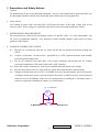
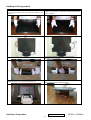
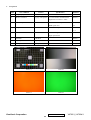
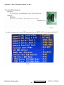
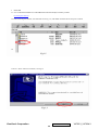
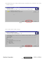
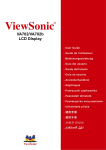
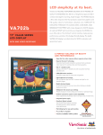
1
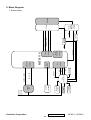
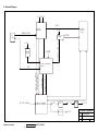
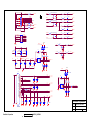
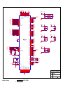
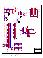
Service Manual
ViewSonic VA702-3
VA702b-3
Model No. VLCDS27998-3W
VLCDS27998-4W
17” Color TFT LCD Display
(VA702-3_VA702b-3_SM Rev. 1a May 2006)
ViewSonic 381 Brea Canyon Road, Walnut, California 91789 USA – (800) 888-8583
Copyright
Copyright © 2006 by ViewSonic Corporation. All rights reserved. No part of this publication
may be reproduced, transmitted, transcribed, stored in a retrieval system, or translated into any
language or computer language, in any form or by any means, electronic, mechanical, magnetic,
optical, chemical, manual or otherwise, without the prior written permission of ViewSonic
Corporation.
Disclaimer
ViewSonic makes no representations or warranties, either expressed or implied, with respect to
the contents hereof and specifically disclaims any warranty of merchantability or fitness for any
particular purpose. Further, ViewSonic reserves the right to revise this publication and to make
changes from time to time in the contents hereof without obligation of ViewSonic to notify any
person of such revision or changes.
Trademarks
Opt quest is a registered trademark of ViewSonic Corporation.
ViewSonic is a registered trademark of ViewSonic Corporation.
All other trademarks used within this document are the property of their respective owners.
Revision History
Revision
SM Editing Date
1a
05/02/2006
ECR Number
ViewSonic Corporation
Description of Changes
Editor
Initial Release
J. Chang
Confidential - Do Not Copy
i
VA702-3_VA702b-3
TABLE OF CONTENTS
1.
Precautions and Safety Notices
1
2.
Specification
3
3.
Front Panel Function Control Description
7
4.
Circuit Description
9
5.
Adjustment Procedure
17
6.
Troubleshooting Flow Chart
40
7.
Recommended Spare Parts List
42
8.
Exploded Diagram and Exploded Parts List
45
9.
Block Diagram
49
10. Schematic Diagrams
51
11. PCB Layout Diagrams
57
ViewSonic Corporation
Confidential - Do Not Copy
ii
VA702-3_VA702b-3
1. Precautions and Safety Notices
1. Caution :
No modification of any circuit should be attempted . Service work should only be performed after you
are thoroughly familiar with all of the following safety checks and servicing guide line
2. Safety Check :
Care should be taken while servicing this LCD display. Because of the high voltage used in the
inverter circuit. These voltage are exposed in such areas as the associated transformer circuits .
3. POWER SUPPLY REQUIREMENTS
The external power converter for this display utilizes AC and DC cords , AC cord is detachable , but
DC cord is permanently attached . Any attempt to replace another adapter could result in serious
problem on the display .
4. LEAKAGE CURRENT HOT CHECK
4-1 Plug the AC cord directly into the AC outlet. Do not use an isolation transformer during this
check.
4-2 Connect a 1500 ohm , 10 watt resistor , paralleled by a 0.15uF capacitor between each metallic
part and a good earth ground
4-3 Use an AC voltmeter with 1000 ohm / volt or more sensitivity and measure the AC voltage
across the combination 1500 ohm resistor and 0.15uF capacitor.
4-4 Move the resistor connection to each exposed metallic part and measure the voltage.
4-5 Reverse the polarity of the AC plug in the AC outlet and repeat the above measurement.
4-6 Voltage measured must not exceed 1.5 volt RMS, from any exposed metallic part to the ground.
A leakage current tester may be used in the above hot check, in which case any circuit measured
must not exceed 1.0 milliamp. In the case of a measurement exceeding the 1.0 milliamp value, a
rework is required to eliminate the chance of a shock hazard .
AC VOLTMETER
V
0.15u
.
To Metal Parts
1500
10W
ViewSonic Corporation
Earth Ground
Confidential - Do Not Copy
1
VA702-3_VA702b-3
Handling & Placing method
Correct methods :
Only touch the metal-frame of the panel or the front
cover of the monitor .Do not touch the surface of the
polarizer .
Incorrect Methods :
Surface of the panel is pressed by fingers & this may
cause “ MURA “
Take out the monitor with cushion
Take out the monitor by grasping the LCD panel.
That may cause “ MURA“.
Place the monitor on a clean & soft foam pad .
Place the monitor on foreign objects .
That could scratch the surface of panel
ViewSonic Corporation
Confidential - Do Not Copy
2
VA702-3_VA702b-3
2. Specification
GENERAL REQUIREMENTS
General Specifications
Test Resolution & Frequency
1280 x 1024 @ 60Hz
Test Image Size
Full Size
Contrast and Brightness Controls
Factory Default: Contrast = 70%, Brightness = 100%
SIGNAL INTERFACE
Video Interface
Analog Input Connector
DB-15 (Analog)
Video Cable Strain Relief
Equal to twice the weight of the monitor for five minutes.
Video Cable Connector DB-15 Pinout
Compliant DDC 2B.
Video Signals
Video RGB (Analog)
Video Impedance
75 Ohms (Analog)
Maximum PC Video Signal
950 mV with no damage to monitor
Maximum Mac Video Signal
1250 mV with no damage to monitor
Sync Signals
TTL
DDC 1/2B
Compliant with Revision 1.3
Video Compatibility
Shall be compatible with all PC type computers, Macintosh computers,
and after market
Resolution Compatibility
video cards.
640 x 350, 640 x 480, 720 x 400 (640 x 400), 800 x 600, 832 x 624,
1024 x 768, 1280 x 720, 1280 x 1024
Exclusions
Not compatible with interlaced video.
Power
Power Supply
Internal Power Supply
Part Number: ADP-40AFB
Input Voltage Range
90 to 264 VAC
Input Frequency Range
47.5 to 63 Hertz
Short Circuit Protection
OUTPUT CAN BE SHORTED WITHOUT DAMAGE.
Over Current Protection
4.5 A TYPICAL AT 12 VDC
Leakage Current
3.5MA (MAX) AT 254VAC / 60HZ
Efficiency
Fuse
70 % TYPICAL AT 115VAC FULL LOAD
INTERNAL AND NOT USER REPLACEABLE
Power Dissipation
36 WATTS (MAX)
Max Input AC Current
1.2 ARMS @ 90VAC, 0.8 ARMS @180VAC
ViewSonic Corporation
Confidential - Do Not Copy
3
VA702-3_VA702b-3
ELECTRICAL REQUIREMENTS
Horizontal / Vertical Frequency
Horizontal Frequency
30 – 80 kHz
Vertical Refresh Rate
50 –85 Hz.
Maximum Pixel Clock
135 MHz
Sync Polarity
Independent of sync polarity.
Primary Presets
Primary Preset
1280 x 1024 @ 60Hz
Look up table timing
<<Analog>>
640 x 350 @ 70Hz, 31.5kHz
640 x 480 @ 60Hz, 31.5kHz
640 x 480 @ 67Hz, 35.0kHz
640 x 480 @ 75Hz, 37.5kHz
640 x 480 @ 72Hz, 37.9kHz
640 x 480 @ 85Hz, 43.27kHz
720 x 400 @ 70Hz, 31.5kHz
800 x 600 @ 56Hz, 35.1kHz
800 x 600 @ 60Hz, 37.9kHz
800 x 600 @ 75Hz, 46.9kHz
800 x 600 @ 72Hz, 48.1kHz
800 x 600 @ 85Hz, 53.7kHz
832 x 624 @ 75Hz, 49.7kHz
1024 x 768 @ 60Hz, 48.4kHz
1024 x 768 @ 70Hz, 56.5kHz
1024 x 768 @ 72Hz, 58.1kHz
1024 x 768 @ 75Hz, 60.0kHz
1024 x 768 @ 85Hz, 68.67kHz
1280 x 1024 @ 60Hz, 63.4kHz
1280 x 1024 @ 75Hz, 79.97kHz
21. 1280x720 @ 60Hz, 45kHz (HDTV)
Changing Modes
Maximum Mode Change Blank Time, for
image stability. Note:
3 seconds (Max)
1 seconds (Typ) for recognized timings
1) Excluding “Auto Adjust” time
1-2 seconds (Typ) for unrecognized timing
2) Under DOS mode (640 x 350, 720 x 400 & 640 x
.
400),
there is no “Auto Adjust” feature.
3) The monitor needs to do “Auto Adjust” the first
time a new mode is detected.
Mode Change Image
The image shall blank while the monitor changes modes.
ViewSonic Corporation
Confidential - Do Not Copy
4
VA702-3_VA702b-3
LCD Panel
1st Source Panel
QD17EL0711
Type
NORMALLY WHITE, TN, OPTICAL COMPENSATION FILM
Active Size
337.920 (H) x 270.336 (V)
Pixel Arrangement
RGB Vertical Stripe
Pixel Pitch
0.264 mm
Glass Treatment
# of Backlights
Backlight Life
ANTI GLARE
4 CCFL EDGE-LIGHT (2 TOP / 2 BOTTOM)
50,000 HOURS (TYP) / 40,000 HOURS (MIN)
260 CD/M2 (TYP AFTER 30 MINUTE WARM UP)
220 CD/M2 (MIN AFTER 30 MINUTE WARM UP)
Luminance –
Condition:
CT = 6500K, Contrast = Max, Brightness = Max
Brightness Uniformity
75 % Entire Area (minimum)
Contrast Ratio
500:1 (Typ), 300:1 (Min)
Color Depth
16 million colors (6 bit panel)
Viewing Angle (Horizontal)
140 deg @ CR>10, 160 deg @ CR>5
Viewing Angle (Vertical)
125 deg @ CR>10, 145 deg @ CR>5
Response Time
8 ms (Tr= 6 ms, Tf = 2 ms) (Typ)
10%-90% @ Ta=25°C
TBD ms (Tr= TBD ms, Tf = TBD ms) (Max)
Panel Defects
Please see Panel Quality Specifications.
MECHANICAL
Dimensions (Base attached unless otherwise specified)
Width
377.6 mm
Height
374.0 mm
Depth
195.6 mm
Depth (Head Only)
55.0 mm
Monitor Weight
4.1 kg / 9.0 lbs
Packaging Specification
Width
450 mm
Height
522 mm
Depth
135 mm
Gross Weight
5.2 kg (11.45 lb)
# units per Pallet
36/72 (air/sea)
20’/40’Container Loading, Palletized
720/1728 pieces
Ergonomics
Tilt Up
20 DEGREES MINIMUM
Tilt Down
-5 degrees
Swivel Right
0 degrees
Swivel Left
0 degrees
Height Adjust
0 mm
Pivot
0 DEGREES (CLOCKWISE)
ViewSonic Corporation
Confidential - Do Not Copy
5
VA702-3_VA702b-3
ENVIRONMENTAL
Environmental Conditions
Operating Temperature
0°C to +40°C
Storage Temperature
-20°C to +60°C
Operating Relative Humidity
20% to 90% RH Non-Condensing
Storage Relative Humidity
5% to 90% RH Non-Condensing
Operating Altitude
0 to +3,000 meters
Storage Altitude
0 to +12,000 meters
ViewSonic Corporation
Confidential - Do Not Copy
6
VA702-3_VA702b-3
3. Front Panel Function Control Description
Main Menu
With On View controls
Front Control Panel
shown below in detail
Displays the control screen for the
highlighted control. Also toggles
between two controls on some screens.
Also a shortcut to auto image adjust
Displays the Main Menu or
exits the control screen
and saves adjustments.
Power light
Green = ON
Orange=power
saving
Scrolls through menu options and
adjusts the displayed control.
Also a shortcut to display the
Contrast adjustment control screen.
Power On / Off
ViewSonic Corporation
Confidential - Do Not Copy
7
VA702-3_VA702b-3
ViewSonic VE702/b -3
Main Menu Controls
Adjust the menu items shown below by using the up and down buttons.
A. Auto Image Adjust automatically sizes, centers, and fine tunes the video signal to eliminate waviness and distortion.
Press the [2] button to obtain a sharper image.
NOTE: Auto Image Adjust works with most common video cards. If this function does not work on your LCD display,
then lower the video refresh rate to 60 Hz and set the resolution to its pre-set value.
B. Contrast adjusts the difference between the image background (black level) and the foreground (white level).
C. Brightness adjusts the lamps current to control the screen brightness.
D. Color Adjust provides several color options: preset color temperatures and Custom User Color which allows you to adjust
red (R), green (G), and blue (B). The factory setting for this product is 6500K (6500° Kelvin).
9300K — Adds blue to the screen image for cooler white (used in most office settings with fluorescent lighting).
5400K — Adds red to the screen image for warmer white and richer red.
Custom User Color — Individual adjustments for red, green, and blue.
1 To select color (R, G or B) press button [2].
2 To adjust selected color, press p or q .
3 When you are finished making all color adjustments, press button [1] twice.
E. Information displays the timing mode (video signal input) coming from the graphics card in your computer. See your
graphic card’s user guide for instructions on changing the resolution and refresh rate (vertical frequency). VESA 1280 x
1024 @ 60 Hz (recommended) means that the resolution is 1280 x 1024 and the refresh rate is 60 Hertz.
F.
Manual Image Adjust controls are explained below:
H. Size (Horizontal Size) adjusts the width of the screen image.
NOTE: Vertical size is automatic with your LCD display.
H./V. Position adjusts horizontal and vertical position of the screen image. You can toggle between Horizontal and
Vertical by pressing button [2]. Horizontal moves the screen image to the left or to the right. Vertical moves the screen image
up and down.
Fine Tune sharpens focus by aligning the illuminated text and/or graphic characters.
Sharpness adjusts the clarity and focus of the screen image.
Setup Menu controls are explained below:
Language allows you to choose the language used in the menus and control screens.
Resolution Notice displays the recommended resolution for this LCD display.
Enable allows the Resolution Notice to appear on-screen.
Disable will not allow the Resolution Notice to appear on-screen.
OSD Timeout sets the length of time an on-screen display screen is displayed. For example,
with a“15 second”
setting, if a control is not pushed within 15 seconds, the display OSD disappears.
G. OSD Position allows you to move the on-screen display menus and control screens.
H. Memory Recall returns adjustments to the original factory settings if the display is operating in a factory Preset Timing
Mode listed in this user guide.
ViewSonic Corporation
Confidential - Do Not Copy
8
VA702-3_VA702b-3
4. Circuit Description
1.
Outline
1.1 POWER On/Off , LED, Button"2" , Up arrow- button , Down arrow button , Button"1" , button , Down arrow button ,
Button"1" , on the front panel.
1.2 Video signal connector, and AC-IN are located on the back side of the cabinet.
1.3 OSD menu includes the following function;
AUTO IMAGE ADJUST
CONTRAST / BRIGHTNESS
COLOR ADJUST
INFORMATION
MANUAL IMAGE ADJUST
SETUP MENU
MEMORY RECALL
1.4 CONTRAST and BRIGHTNESS can be directly controlled with UP / DN key.
.
2.
CONNECTORS
2.1 AC inlet : CEE22 typed connector
2.2 Video signal connector 14P + Mini D-Sub
PIN
MNEMONI
SIGNAL
1
RV
Red Video
2
GV
Green Video
3
BV
Blue Video
4
NC
None
5
GND
Ground(DDC return)
6
RG
Red GND
7
GG
Green GND
8
BG
Blue GND
9
+5V
+ 5V (for DDC)
10
SG
Sync GND
11
NC
None
12
SDA
DDC Data
13
HS
Horizontal Sync
14
VS
Vertical Sync
15
SCL
DDC Clock
ViewSonic Corporation
Confidential - Do Not Copy
9
VA702-3_VA702b-3
3.
ELECTRICAL SPECIFICATIONS
3.1 Standard conditions
Display Area
338 x 270 mm
Video Signal
0.7 Vpp
Contrast
70%
Brightness
Max.
Ambient
20 +/- 5 °
C
Input
AC
Warming up
> 30 min
Display
1280 x 1024
3.2 POWER
3.2.1
Power supply
Input Voltage
90 -240 ~Volts
Power Frequency
50/ 60 Hz +/-3Hz
Input current
<1.5Arms @ 90Vac
<0.75Arms@240Vac
3.2.2
Inrush current
90A(max.) at 230Vac
Power consumption
50Watt
Output Voltage
@0-3.0A load 12Vdc +/-5%
Power Management
State
Power
Indicator
On
36Watt
Green
Standby
<1Watt
Amber
Off
<1Watt
3.3 Acceptable timing
If your timing is within following specification, this LCD display can automatically function with a certain position.
Horizontal: Sync frequency : 30~81 kHz
Vertical: Sync frequency : 56~85Hz(1280x1024,75Hz)
3.4 Signal level and input impedance
3.4.1
Video Signal level This LCD display is adjusted at the factory using 0,7 Vp-p Video signal.
3.4.2
Sync Signal level
H/V Separate : TTL level
3.4.3
Input impedance
Video input : 75 ohms
Sync input : > 1 k ohms
4.
SIGNAL CABLE : Signal cable with Mini D-Sub 15P connectors at both ends.
ViewSonic Corporation
Length : 1.8 meter.
Confidential - Do Not Copy
10
VA702-3_VA702b-3
5. EDID data
QDI QD17EL07 v11
VA702-3
Time: 15:03:33
Date: Wed Oct 19, 2005
______________________________________________________________________
______________________________________________________________________
VIEWSONIC CORPORATION
EDID Version # 1, Revision # 3
DDCTest For: ViewSonic VA702-3SERIES
______________________________________________________________________
______________________________________________________________________
EDID Block 0, Bytes 0-127
128 BYTES OF EDID CODE:
0 1 2 3 4 5 6 7 8 9
________________________________________
0 | 00 FF FF FF FF FF FF 00 5A 63
10 | 1D B5 01 01 01 01 01 0F 01 03
20 | 08 22 1B 78 2E 59 95 A4 57 47
30 | 9C 24 15 50 54 BF EF 80 81 80
40 | 81 40 71 4F 61 59 45 59 31 59
50 | 01 01 01 01 30 2A 00 98 51 00
60 | 2A 40 30 70 13 00 52 0E 11 00
70 | 00 1E 00 00 00 FF 00 51 35 4B
80 | 30 35 30 31 30 30 30 30 31 0A
90 | 00 00 00 FD 00 32 55 1E 52 0E
100 | 00 0A 20 20 20 20 20 20 00 00
110 | 00 FC 00 56 41 37 30 32 2D 33
120 | 53 45 52 49 45 53 00 92
______________________________________________________________________
(08-09) ID Manufacturer Name ________________ = VSC
(11-10) Product ID Code _____________________ = B51D
(12-15) Last 5 Digits of Serial Number ______ = Not Used
(16)
Week of Manufacture _________________ = 01
(17)
Year of Manufacture _________________ = 2005
(10-17) Complete Serial Number ______________ = See Descriptor Block
(18)
EDID Version Number _________________ = 1
(19)
EDID Revision Number ________________ = 3
(20)
VIDEO INPUT DEFINITION:
Analog Signal
0.700, 0.300 (1.000 Vp-p)
Separate Syncs
(21)
Maximum Horizontal Image Size ________________
= 340 mm
(22)
Maximum Vertical Image Size __________________
= 270 mm
(23)
Display Gamma ________________________________
= 2.20
(24)
Power Management and Supported Feature(s):
Active Off/Very Low Power, Standard Default Color Space,
Preferred Timing Mode
Display Type = R/G/B Color
(25-34) CHROMA INFO:
Red X - 0.642 Green X - 0.279 Blue X - 0.143 White X - 0.313
Red Y - 0.341 Green Y - 0.610 Blue Y - 0.083 White Y - 0.329
(35)
ESTABLISHED TIMING I:
720 X 400 @ 70Hz (IBM,VGA)
640 X 480 @ 60Hz (IBM,VGA)
640 X 480 @ 67Hz (Apple,Mac II)
640 X 480 @ 72Hz (VESA)
640 X 480 @ 75Hz (VESA)
800 X 600 @ 56Hz (VESA)
800 X 600 @ 60Hz (VESA)
(36)
ESTABLISHED TIMING II:
800 X 600 @ 72Hz (VESA)
800 X 600 @ 75Hz (VESA)
832 X 624 @ 75Hz (Apple,Mac II)
1024 X 768 @ 60Hz (VESA)
1024 X 768 @ 70Hz (VESA)
1024 X 768 @ 75Hz (VESA)
1280 X 1024 @ 75Hz (VESA)
(37)
Manufacturer's Reserved Timing:
1152 X 870 @ 75Hz (Apple,Mac II)
ViewSonic Corporation
Confidential - Do Not Copy
11
VA702-3_VA702b-3
(38-53)
Standard Timing Identification:
1280 X 1024 @60Hz
1280 X 960 @60Hz
1152 X 864 @75Hz
1024 X 768 @85Hz
800 X 600 @85Hz
640 X 480 @85Hz
Not Used
Not Used
______________________________________________________________________
(54-71) Detailed Timing / Descriptor Block 1:
1280x1024 Pixel Clock: 108.00 MHz
______________________________________________________________________
Horizontal Image Size: 338 mm
Vertical Image Size: 270 mm
Refreshed Mode: Non-Interlaced
Normal Display - No Stereo
Horizontal:
Active Time: 1280 pixels
Sync Offset: 48 pixels
Border: 0 pixels
Blanking Time: 408 pixels
Sync Pulse Width: 112 pixels
Frequency: 63.98 KHz
Vertical:
Active Time: 1024 lines
Sync Offset: 1 lines
Border: 0 lines
Blanking Time: 42 lines
Sync Pulse Width: 3 lines
Frequency: 60.02 Hz
Digital Separate, Horizontal Polarity (+) Vertical Polarity (+)
______________________________________________________________________
(72-89) Detailed Timing / Descriptor Block 2:
Monitor Serial Number:
Q5K050100001
______________________________________________________________________
(90-107) Detailed Timing / Descriptor Block 3:
Monitor Range Limits:
Min Vertical Freq - 50 Hz
Max Vertical Freq - 85 Hz
Min Horiz. Freq - 30 KHz
Max Horiz. Freq - 82 KHz
Pixel Clock - 140 MHz
Secondary GTF - Not Supported
______________________________________________________________________
(108-125) Detailed Timing / Descriptor Block 4:
(126)
(127)
Monitor Name:
VA702-3SERIES
No Extension EDID Block(s)
CheckSum OK
ViewSonic Corporation
Confidential - Do Not Copy
12
VA702-3_VA702b-3
VA702b-3
Time: 15:33:23
Date: Wed Oct 19, 2005
______________________________________________________________________
______________________________________________________________________
VIEWSONIC CORPORATION
EDID Version # 1, Revision # 3
DDCTest For: ViewSonic VA702-3SERIES
______________________________________________________________________
______________________________________________________________________
EDID Block 0, Bytes 0-127
128 BYTES OF EDID CODE:
0 1 2 3 4 5 6 7 8 9
________________________________________
0 | 00 FF FF FF FF FF FF 00 5A 63
10 | 1D B5 01 01 01 01 01 0F 01 03
20 | 08 22 1B 78 2E 59 95 A4 57 47
30 | 9C 24 15 50 54 BF EF 80 81 80
40 | 81 40 71 4F 61 59 45 59 31 59
50 | 01 01 01 01 30 2A 00 98 51 00
60 | 2A 40 30 70 13 00 52 0E 11 00
70 | 00 1E 00 00 00 FF 00 51 35 4C
80 | 30 35 30 31 30 30 30 30 31 0A
90 | 00 00 00 FD 00 32 55 1E 52 0E
100 | 00 0A 20 20 20 20 20 20 00 00
110 | 00 FC 00 56 41 37 30 32 2D 33
120 | 53 45 52 49 45 53 00 91
______________________________________________________________________
(08-09) ID Manufacturer Name ________________ = VSC
(11-10) Product ID Code _____________________ = B51D
(12-15) Last 5 Digits of Serial Number ______ = Not Used
(16)
Week of Manufacture _________________ = 01
(17)
Year of Manufacture _________________ = 2005
(10-17) Complete Serial Number ______________ = See Descriptor Block
(18)
EDID Version Number _________________ = 1
(19)
EDID Revision Number ________________ = 3
(20)
VIDEO INPUT DEFINITION:
Analog Signal
0.700, 0.300 (1.000 Vp-p)
Separate Syncs
(21)
Maximum Horizontal Image Size ________________
= 340 mm
(22)
Maximum Vertical Image Size __________________
= 270 mm
(23)
Display Gamma ________________________________
= 2.20
(24)
Power Management and Supported Feature(s):
Active Off/Very Low Power, Standard Default Color Space,
Preferred Timing Mode
Display Type = R/G/B Color
(25-34) CHROMA INFO:
Red X - 0.642 Green X - 0.279 Blue X - 0.143 White X - 0.313
Red Y - 0.341 Green Y - 0.610 Blue Y - 0.083 White Y - 0.329
(35)
ESTABLISHED TIMING I:
720 X 400 @ 70Hz (IBM,VGA)
640 X 480 @ 60Hz (IBM,VGA)
640 X 480 @ 67Hz (Apple,Mac II)
640 X 480 @ 72Hz (VESA)
640 X 480 @ 75Hz (VESA)
800 X 600 @ 56Hz (VESA)
800 X 600 @ 60Hz (VESA)
(36)
ESTABLISHED TIMING II:
800 X 600 @ 72Hz (VESA)
800 X 600 @ 75Hz (VESA)
832 X 624 @ 75Hz (Apple,Mac II)
1024 X 768 @ 60Hz (VESA)
1024 X 768 @ 70Hz (VESA)
1024 X 768 @ 75Hz (VESA)
1280 X 1024 @ 75Hz (VESA)
(37)
Manufacturer's Reserved Timing:
1152 X 870 @ 75Hz (Apple,Mac II)
(38-53) Standard Timing Identification:
1280 X 1024 @60Hz
1280 X 960 @60Hz
ViewSonic Corporation
Confidential - Do Not Copy
13
VA702-3_VA702b-3
1152 X 864 @75Hz
1024 X 768 @85Hz
800 X 600 @85Hz
640 X 480 @85Hz
Not Used
Not Used
______________________________________________________________________
(54-71) Detailed Timing / Descriptor Block 1:
1280x1024 Pixel Clock: 108.00 MHz
______________________________________________________________________
Horizontal Image Size: 338 mm
Vertical Image Size: 270 mm
Refreshed Mode: Non-Interlaced
Normal Display - No Stereo
Horizontal:
Active Time: 1280 pixels
Sync Offset: 48 pixels
Border: 0 pixels
Blanking Time: 408 pixels
Sync Pulse Width: 112 pixels
Frequency: 63.98 KHz
Vertical:
Active Time: 1024 lines
Sync Offset: 1 lines
Border: 0 lines
Blanking Time: 42 lines
Sync Pulse Width: 3 lines
Frequency: 60.02 Hz
Digital Separate, Horizontal Polarity (+) Vertical Polarity (+)
______________________________________________________________________
(72-89) Detailed Timing / Descriptor Block 2:
Monitor Serial Number:
Q5L050100001
______________________________________________________________________
(90-107) Detailed Timing / Descriptor Block 3:
Monitor Range Limits:
Min Vertical Freq - 50 Hz
Max Vertical Freq - 85 Hz
Min Horiz. Freq - 30 KHz
Max Horiz. Freq - 82 KHz
Pixel Clock - 140 MHz
Secondary GTF - Not Supported
______________________________________________________________________
(108-125) Detailed Timing / Descriptor Block 4:
(126)
(127)
6.
Monitor Name:
VA702-3SERIES
No Extension EDID Block(s)
CheckSum OK
THEORY OF OPERATION
This section describes the function of the LCD monitor per functional block.
This monitor includes MB board, power board and button board.
6.1 MB BOARD
The MB board is a two-layer, single-landed design with ground and internal planes provided. DC power from the power board enter
the board through a 6P connector. Other connector on the board is for button board .The VGA cable is a signal cable that contains
video signal, sync signal and DDC signal from PC VGA adapter. This system board consists of 4 functional areas : flat panel
controller, MCU with flash ROM , power regulator .
6.1.1 Flat panel controller… MST8111A (U3)
The heart of the system board is MStart MST8111A.
The MST8111A is a graphics processing IC for LCD monitor. It
provides all key IC functions required for LCD panel. On-chip functions include a high-speed triple-ADC , PLL, high scaling
engine, OSD controller.
a) Clock Generation :
Crystal Input Clock (TCLK and XTAL). This is the input pair to an internal crystal oscillator and corresponding logic. A
ViewSonic Corporation
Confidential - Do Not Copy
14
VA702-3_VA702b-3
14.318 MHz crystal is recommended.
b) Analog to Digital Converter:
The MST8111A chip has three ADC's (analog-to-digital converters), one for each color (red, green and blue) .The analog
RGB signals are connected to MST8111A as described below
Pin Name
Pin Number
Red +
63
Red -
62
Green +
60
Green -
59
Blue +
58
Blue -
57
c) OSD : The MST8111A has a fully programmable ,high-quality OSD controller. The on-chip static RAM(4096 words by 24 bits)
stores the cell map and the cell definitions.
d) MTV312 Micro controller: The MTV312 micro controller(MCU) serves as the system micro controller. It’s programs the
MST8111A and manages other devices in the system such as the keypad, the backlight, LED, audio and non-volatile RAM.
using general purpose input/output (GPIO) pins.
Pin number
Pin Name
Pin Number Usage
21
P1.3
Key / Power on
13
P3.4
NV_RAM (U4) SDA
14
P3.5
NV_RAM (U4) SCL
25
P1.7
Key_down
9
P6.3
Key_right
24
P1.6
Key_up
16
P6.2
Key_left
37
P4.1
Key_mute
34
P5.6
VGA connector
23
P1.5
Key_select
42
P5.3
LED_red
41
P5.4
LED_green
32
P6.6
LCD panel power1 on / off control
3
P5.0
LCD panel power2 on / off control
36
P4.0
Backlight on / off control
,off
e) Panel Power Sequencing ( VDDCTRL1, 2) ( Pin 32, 3) : The MTV312 has two dedicated outputs VDDCTRL1 and
2
( Pin32 and Pin3) to control LCD power sequencing once data and control signals are stable.
f) Panel interface (Pin 1~25, Pin75~128) : The MTV312 driver interface is highly programmable. It supports dual bus / dual port
for SXGA drivers.
6.1.2 Power Regulator MC34063A (U6),AIC1739 (Q4) : The MC34063A is a monolithic control IC containing the primary functions
required for DC to DC converters. The device consists of an internal temperature compensated reference, comparator, controlled
duty cycle.
ViewSonic Corporation
Confidential - Do Not Copy
15
VA702-3_VA702b-3
Oscillator with an active current sense circuit. Desired output voltage are determined by the equation,
Volt = 1.25
( 1 + R67 / R66), In this case, the output voltage are 3.3 Volts
The AIC1739 is a low dropout positive adjustable regulator with minimum of 300mA output current capability.
So it is well suited for 3.3 V and 2.5 V Regulator.
6.1.3 Power Regulator MC34063A (U7) : The MC34063A is a monolithic control IC containing the primary functions required for DC
to DC converters. The device consists of an internal temperature compensated reference, comparator, controlled duty cycle.
Oscillator with an active current sense circuit. Desired output voltage are determined by the equation,
Volt = 1.25
( 1 + R85 / R86), In this case, the output voltage are 5.0 Volts for panel power.
6.2 Power(Inverter) Board
This is a specific power(inverter) power board for VA702-3 monitor 40W 12V 3.5A output power and backlight which
converters 12 Vdc to drive four cold cathode fluorescence tubes.
6.2.1 Inverter Electrical specification described as below.
Input
Output
Rated Input Voltage
12Vdc
Input Voltage Range
11.4 ~ 12.6 Vdc
Input Current
<2A
On / Off control Voltage
2~3.3 for on , 0~1 for off
Rated Output Strike-on Voltage
1500Vrms
Rated Output Voltage
710Vrms at 7mA
Rate Output Frequency
40~50KHz
Rated Ourput Current
7~8 mA
6.2.2 power
This is a general purpose AC / DC adapter which converter 90~240 Vac to a stabilized DC voltage 12 V with rated output
current of 4.16A . Electrical specification described as below.
Rated Input Voltage
90~240 Vac , 50 / 60Hz
Operation Input Voltage
90~260 Vac , 47 ~ 63Hz
Input Current
<1.5A
Inrush Current
<100A@120Vac
Standby Input Voltage
12Vdc
Output Voltage Regulation
+/-5%
Output Ripple & Noise
120mVp-p
Rate Output Current
<3.5A
Turn-on delay
<3secs
ViewSonic Corporation
Confidential - Do Not Copy
16
VA702-3_VA702b-3
5. Adjustment Procedure
OSD Function Menu
1. Main Menu
Press “1” Button (Menu Button) to enter Main Menu:
Press Up Button to the previous page or Down Botton to the next page .
Press “1” Button to exit Main Menu.
(1) Auto Image Adjust Page:
Press “2” Button to do auto image adjust function.
Press “1” Button to exit the page.
(2) Contrast/Brightnes Page:
Press “2” Button to enter Contrast Item.
Press “1” Button to exit the page.
1) Contrast Item
Press Up Button to make contrast high.
Press Down Button to make contrast low.
Press “2” Button to enter Brightness Item.
Press “1” Button to exit the item.
2) Brightness Item
Press Up Button to make brightness high.
Press Down Button to make brightness low.
Press “2” Button to enter Contrast Item.
Press “1” Button to exit the item.
(3) Color Adjust Page:
Press “2” Button to enter Color Adjust page.
Press “1” Button to exit the page.
Press Up Button to the previous item or Down Botton to the next item.
1)
2)
3)
4)
sRGB Item
9300K Item
6500K Item
5400K Item
Press “2” Button to select current Item.
Press “1” Button to exit current item.
5) User Color Item
Press “2” Button to enter User Color item.
Press “1” Button to exit User Color item.
Red,Green,Blue Options:
Press “2” Button to switch among the options.
Press “1” Button to exit the options.
Press Up Button to make current option high.
ViewSonic Corporation
Confidential - Do Not Copy
17
VA702-3_VA702b-3
Press Down Button to make current option low.
(4) Information Page:
Press “2” Button to show the information.
Press “1” Button to exit Information page.
(5) Manual Image Adjust Page:
Press “2” Button to enter Manual Image Adjust page.
Press “1” Button to exit Manual Image Adjust page.
Press Up Button to the previous item or Down Botton to the next item.
1) H./V. Position Item
Press “2” Button to enter H./V. Position item.
Press “1” Button to exit H./V. Position item.
a) Horizontal Position Option:
Press “2” Button to enter the Vertical Position option.
Press “1” Button to exit Horizontal Position option.
Press Up Button to make current option high.
Press Down Button to make current option low
b) Vertical Position Option:
Press “2” Button to enter the Horizontal Position option.
Press “1” Button to exit Vertical Position option.
Press Up Button to make current option high.
Press Down Button to make current option low
2) Horizontal Size Item
Press “2” Button to enter Horizontal Sizeitem.
Press “1” Button to exit Horizontal Size item.
Press Up Button to make current item high.
Press Down Button to make current item low.
3) Fine tune Item
Press “2” Button to enter Fine tune item.
Press “1” Button to exit Fine tune item.
Press Up Button to make current item high.
Press Down Button to make current item low.
4) Sharpness Item
Press “2” Button to enter Sharpness item.
Press “1” Button to exit Sharpness item.
Press Up Button to make current item high.
ViewSonic Corporation
Confidential - Do Not Copy
18
VA702-3_VA702b-3
Press Down Button to make current item low.
(6) Setup Menu Page:
Press “2” Button to enter Setup Menu page.
Press “1” Button to exit Setup Menu page.
Press Up Button to the previous item or Down Botton to the next item.
1) Language Select Item
Press “2” Button to enter Language Select item.
Press “1” Button to exit Language Select item.
Press Up Button to the previous option or Down Botton to the next
option.
English,French… … ..Option
Press “2” Button to select the language.
Press “1” Button to exit the option.
2) Resolution Notice Item
Press “2” Button to enter Resolution Notice item.
Press “1” Button to exit Resolution Notice item.
Enable,Disable Option
Press “2” Button to select the option.
Press “1” Button to exit the option
Press Up Button to the previous option or Down Botton to the next
option.
3) OSD Position Item
Press “2” Button to enter OSD Position item.
Press “1” Button to exit OSD Position item.
a) Horizontal Position Option
Press “2” Button to enter the Vertical Position option.
Press “1” Button to exit Horizontal Position option.
Press Up Button to make current option high.
Press Down Button to make current option low
b) Vertical Position Option:
Press “2” Button to enter the Horizontal Position option.
Press “1” Button to exit Vertical Position option.
Press Up Button to make current option high.
Press Down Button to make current option low
4) OSD Time Out Item
Press “2” Button to enter OSD Time Out item.
ViewSonic Corporation
Confidential - Do Not Copy
19
VA702-3_VA702b-3
Press “1” Button to exit OSD Time Out item.
Press Up Button to make OSD time out long.
Press Down Button to make OSD time out short.
5) OSD Background Item
Press “2” Button to enter OSD Background item.
Press “1” Button to exit OSD Background item.
Enable,Disable Option
Press “2” Button to select the option.
Press “1” Button to exit the option.
Press Up Button to the previous option or Down Botton to the next
option.
(7) Memory Recall Page
Press “2” Button to do the memory recall function.
Press “1” Button to exit the page.
2. Other Menu:
(1) Contrast Dialog
Press Down Button to enter the Contrast Dialog.
Press “1” Button to exit the Contrast Dialog.
Press “2” Button to enter the Brightness Dialog.
Press Up Button to make contrast high.
Press Down Button to make contrast low.
(2) Auto Image Adjust Dialog
Press “2” Button to do the auto image adjust function.
ViewSonic Corporation
Confidential - Do Not Copy
20
VA702-3_VA702b-3
Function test
(1) Test equipment
Color video Signal & pattern generator (or PC with SXGV resolution )
(2) Test condition
Warm-up at least 30mins is necessary under following condition
2.
1.
room temperature
2.
With full-white screen , RGB , black pattern
3.
with cycled display modes.
before function test & alignment :
Test display modes
Item
Timing
Analog
1
640 x 350 @ 70Hz, 31.5kHz
Yes
2
640 x 400 @ 60Hz, 31.5kHz
Yes
3
640 x 400 @ 70Hz, 31.5kHz
Yes
4
640 x 480 @ 50Hz, 24.7kHz
Yes
5
640 x 480 @ 60Hz, 31.5kHz
Yes
6
640 x 480 @ 67Hz, 35.0kHz
Yes
7
640 x 480 @ 72Hz, 37.9kHz
Yes
8
640 x 480 @ 75Hz, 37.5kHz
Yes
9
640 x 480 @ 85Hz, 43.27kHz
Yes
10
720 x 400 @ 70Hz, 31.5kHz
Yes
11
800 x 600 @ 56Hz, 35.1kHz
Yes
12
800 x 600 @ 60Hz, 37.9kHz
Yes
13
800 x 600 @ 75Hz, 46.9kHz
Yes
14
800 x 600 @ 72Hz, 48.1kHz
Yes
15
800 x 600 @ 85Hz, 53.7kHz
Yes
16
832 x 624 @ 75Hz, 49.7kHz
Yes
17
1024 x 768 @ 60Hz, 48.4kHz
Yes
18
1024 x 768 @ 70Hz, 56.5kHz
Yes
19
1024 x 768 @ 72Hz, 58.1kHz
Yes
20
1024 x 768 @ 75Hz, 60.0kHz
Yes
21
1024 x 768 @ 85Hz, 68.67kHz
Yes
22
1152 x 864 @ 75Hz, 67.5kHz
Yes
23
1152 x 870 @ 75Hz, 68.7kHz
Yes
24
1280 x 1024 @ 60Hz, 63.4kHz
Yes
25
1280 x 1024 @ 75Hz, 79.97kHz
Yes
26
1280x 720 @ 60Hz, 45kHz (HDTV)
Yes
ViewSonic Corporation
Confidential - Do Not Copy
21
VA702-3_VA702b-3
3.
Test pattern
Item
Test condition
Pattern
Specification
Remark
1
Frequency & performance
Cross-hatch pattern
No noise is allow & all color is clear
Pattern 1
2
Monitor saturation
16-gray scale pattern
3~4 level need to saturated when
Pattern 2
brightness & contrast is 100%
3
4
RGB color performance
Sub-pixel defect
RGB color
RGB color
Check the color temperature of
Pattern 3,
RGB signal color
4, 5
Check the sub-pixel defect
Pattern 3,
4,5
5
Full white
Full white
Check the brightness
,CR &
Pattern 6
bright pixel defect
6
Full black
Full black
Pattern 7
7.
5-cycle pattern
5-cycle pattern
Check the BU
Pattern 8
8.
1-dot pattern
1-dot pattern
Check the flicker
Pattern 9
Pattern 1
Pattern2
Pattern 3
Pattern4
ViewSonic Corporation
Confidential - Do Not Copy
22
VA702-3_VA702b-3
Pattern 5
Pattern6
Pattern 7
Pattern 8
Pattern 9
ViewSonic Corporation
Confidential - Do Not Copy
23
VA702-3_VA702b-3
Firmware update procedure:
When you received a received monitor , please check whether the firmware version.
If not , please following procedure to upgrade to the latest version .
1.
2.
Equipment needed :
-
VA702/b-3
-
PC ( Personal computer )
-
LPT cable
-
Fixture (LM5ISP)
-
Firmware upgrade program
Print port
Fixture
VA702/b-
LPT cable
Connection :
To PC
To monitor
ViewSonic Corporation
Confidential - Do Not Copy
24
VA702-3_VA702b-3
Appendix A : How to install the software for ISP :
ViewSonic Corporation
Confidential - Do Not Copy
25
VA702-3_VA702b-3
1.
Install ISP
1.1 User could download ISP river and PORT95NT install from Myson Century website
(www.myson.com.tw)
1.2 After extracting the ZIP file , the total files list as Fig 1.2 , and double click the file of setup.exe to install.
1.3 Press “ Next “ button to continue., see Fig 1.3
ViewSonic Corporation
Confidential - Do Not Copy
26
VA702-3_VA702b-3
1.4 Keep default setting or press “ Change “ button for selecting
the path that you want , and then press “ Next “ button
to continue , see Fig 1.4 .
1.5 Press “ Install “ button to continue , see Fig 1.5
ViewSonic Corporation
Confidential - Do Not Copy
27
VA702-3_VA702b-3
1.6 The installer Information shows package warning , Press “ Ignore “ button to continue .see Fig 1.6 .
1.7 Installation has finished , press “ Finish “ button , see Fig 1.7 .
Fig. 1.7
ViewSonic Corporation
Confidential - Do Not Copy
28
VA702-3_VA702b-3
Appendix B : How to use software to upgrade the BIOS :
2.1 After installation , we could find the shortcut in the setting path or the program bar ( default setting ) , see Fig 2.1 .
2.2 Security file is a key to use ISP function , press “ 確定 “ button , see Fig 2.2 .
ViewSonic Corporation
Confidential - Do Not Copy
29
VA702-3_VA702b-3
2.3 The warning is used to remind user of that different CPU rate may cause ISP function fail .
(it’s limited by IIC protocol ) , press “ 確定 “ button , see Fig 2.3 .
2.4
Press “ Create Security File “ button to key in Security code. Adjusting bar to decrease speed of IIC bus , See Fig.
ViewSonic Corporation
Confidential - Do Not Copy
30
VA702-3_VA702b-3
2.7 Fig 2.7 shows the setting for security code of software ISP . it needs 2 command No. and key in command sequentially for
7C , 4C , 77. The command No. and command must be set by user while coding. About the detailed of setting ,
please refer to section 6 boot code of ISP .
ViewSonic Corporation
Confidential - Do Not Copy
31
VA702-3_VA702b-3
3. Use ISP to program MCU
3.1
Select MTV type first , load the binary or intel hex file that you want to program into the MCU , and select “ AUTO”
item , then press “ RUN “ button , see fig3.1
3.2
If user change the MTV type , it must load file again , or the buffer of load file will be cleared .
3.3
CRC ( cyclic redundancy check ) : the host can check CRC register’s result instead of reading every byte in
flash . The message of Check MCU CRC OK means that the host verify OK for the progress of program .
ViewSonic Corporation
Confidential - Do Not Copy
32
VA702-3_VA702b-3
4. Use ISP to read MCU content
4.1 Only software ISP could read the MCU content , it is according to program the boot code while coding .
The limitation is used for the security of customer’s code. Select “ Read Target “ item , and press “RUN” button , the
MCU content will show as Fig4.1
ViewSonic Corporation
Confidential - Do Not Copy
33
VA702-3_VA702b-3
5 Re-entry the ISP Mode
When you couldn’t select or click “ Reset MCU “ button and enter ISP mode again , you’ll see the message as below :
ViewSonic Corporation
Confidential - Do Not Copy
34
VA702-3_VA702b-3
Note :
(1) Disable the “ Enter ISP Mode ” option to avoid the error message display
(2) If you using the MTV312M64 or before MCU serials , the MCU will always in “ ISP Mode “ even
Programming fail or erase MCU that instead of select or press “ Reset MCU “
ViewSonic Corporation
Confidential - Do Not Copy
35
VA702-3_VA702b-3
Packing procedure
1.1
Paste protection film to protect the monitor (Figure.1)
1.2
Put the monitor in PE bag & seal the with tape . (Figure.2)
Figure.1
Figure.2
1.3
Put the cushion on the monitor (Figure.3)
1.4
Put the monitor into carton & put all the accessories into the carton .Then close the carton . (Figure.4)
(Figure 3)
QSG
ViewSonic Corporation
(Figure 4)
Confidential - Do Not Copy
36
Power cord
VA702-3_VA702b-3
Disassemble monitor
2.1
Take off the hinge caps (Figure 5)
2.2
Lay VA702/b-3 down & take off the screws to remove the base (Figure 6)
(Figure 5)
2.3
Remove the screw cover (Figure 7)
2.4
Take of the screws (Figure 8)
(Figure 6)
Figure 7
2.5
Remove the back cover (Figure 9)
2.6
Take off the screw on the VGA cable (Figure 10)
Figure 8
Figure 9
Figure 10
ViewSonic Corporation
Confidential - Do Not Copy
37
VA702-3_VA702b-3
2.7
Take off the screws on the B/B (Figure 11)
2.8
Remove the B/B from the front-bezel (Figure 12)
Figure 11
2.9
Figure 12
Tear off the AL-foil , all cables on M/B & lamp wires . (Figure 13)
2.10 Take off the screws on the PCB holder & remove the PCB holder with the boards . (Figure 14)
Figure 13
Figure 14
2.11 Take out the screws on M/B & remove the cable between M/B & power board (Figure 15)
2.12
Remove the M/B out (Figure 16)
Figure 15
Figure 16
ViewSonic Corporation
Confidential - Do Not Copy
38
VA702-3_VA702b-3
2.13
Put the PCB holder up-side-down & remove the screws on the power board (Figure 17)
2.14
Remove the power board (Figure 18)
Figure 17
Figure 18
2.15 Separate the bezel & panel (with BKT) & remove the cable on panel (Figure 19)
2.16 Take off the L/R BKT & remove the L/R BKT . (Figure 20)
Figure 19
Figure 20
ViewSonic Corporation
Confidential - Do Not Copy
39
VA702-3_VA702b-3
6. Troubleshooting Flow Chart
1. No Power
ViewSonic Corporation
Confidential - Do Not Copy
40
VA702-3_VA702b-3
2.
No Characters , Missing Color
3 Always show NO SIGNEL
ViewSonic Corporation
Confidential - Do Not Copy
41
VA702-3_VA702b-3
7. Recommended Spare Parts List
RECOMMENDED SPARE PARTS LIST (VA702-3)
ViewSonic Model Number: VLCDS27998-3W
Serial No. Prefix: Q5K
Item
1
2
3
4
5
6
7
8
9
10
11
12
13
14
15
16
17
18
Rev: 1a
Description
ECR/ECN
POWER CORD SP-305+IS-14 3P 1.8M(TWN)B GP
ADP/INV,SLV0315A0450-1057,90~264V REV1A
MAIN BOARD (MST8111A) GP
L7VC (BUTTON/B ASSY) CONTROL BOARD
ADP/INV ADP-40AFA, 90~264V REV1A
L7VC-A2(702) FRONT PANEL
L7VC BACK COVER ASSY(BLACK)
L7VC STAND ASSY(BLACK)
CABLE ASSY L7VC MB-VGA(14/15P,REV1A) GP
CABLE L7VC BUTTON-MB(8P/10P,REV1A) GP
CABLE ASSY L7VC POWER-MB(8P/8P,REV1A) GP
CABLE MB-LCD(30P,100MM,LINKTEC)L9ZA GP
USER GUIDE (VA702B-3) L7VC-A2(HGL7VC07,3A)GP
Accessories:
PC Board
Assembly:
Cabinets:
Cables:
Documentation:
Electronic
Components:
Hardware:
LCD PANEL QD17EL07 REV:11(04,05,P4)8MS SXGA GP
HINGE CAP L7VC(EBL7V023,REV3A)GP
SCREW M3.5*8-B (NI,WASHER)GP
SCREW M3.0*6.0-I(NI) GP
SCREW M3.0*4.0-I(NI) GP
ViewSonic P/N
A-00003642
B-00000936
B-00005786
B-00005787
B-SB-0221-0686
C-00005788
C-BC-0302-0576
C-BS-0303-0509
CB-00000182
CB-00002262
CB-00002263
CB-00005785
DC-00005789
Ref. P/N
DM33T181004
AS05B310202
1SL7VCMB066
1SL7VCBB001
AS020126104
34L7VCLB008
37L7VBCVS46
26L7VSAVS25
DDL7VCPC001
DDL7VCTH004
DDL7VCPB101
DDL9ZALC005
HGL7VC07010
Location
power cord
power board
main board
button board
power board
front bezel assembly
back cover assembly
stand
VGA cable
Button-MB cable
Power-MB
MB-LCD cable
user guide
Universal number#
Q'ty
1
1
1
1
1
1
1
1
1
1
1
1
1
E-00005784
M-MS-0808-7306
M-SCW-0824-6799
M-SCW-0824-6800
M-SCW-0824-6802
AA17EL070A2
EBL7V023017
MM35080BBW2
MM30060IBJ8
MM30040IBJ9
LCD panel
hinge cap
Power/B grounding
PCBAs to metal shielding
panel to L/R bracket
1
1
1
7
10
HAL7V001012
HFL7VC04010
HBL7V005019
HBL7V006015
JXL7V003017
GAL5V002013
EPE bag
carton
cushion
cushion
LCD F film
Rubber foot
1
1
1
1
1
1
Packing Material:
19
20
21
22
23
24
Miscellaneous:
Plastics:
EPE BAG L7V(HAL7V001,REV3A)GP
CARTON (VA702-3) L7VC-A2(HFL7VC04,R3A)GP
END CAP(L) L7VC(HBL7V005,REV3B)GP
END CAP(R) L7VC(HBL7V006,REV3B)GP
LCD FILM L7VC(JXL7V003,REV3B)GP
RUBBER FOOT L5VC(GAL5V002,REV3A) GP
M-MS-0808-8981
P-00005790
P-FM-0602-0840
P-FM-0602-0841
M-MS-0808-7399
M-MS-0808-9251
Remark 1: Above listed items are examples, supplier can expand the rows to add more necessary items.
Remark 2: All revised RSPLs with newly added items or any change made should be highlighted and correlated with the ECN/ECR approved by ViewSonic Corporation. This is to eliminate
repeated cross checks of each item between this version and prior versions.
RECOMMENDED SPARE PARTS LIST (VA702b-3)
ViewSonic Model Number: VLCDS27998-4W
Serial No. Prefix: Q5L
Item
1
2
3
4
5
6
7
8
9
10
11
12
13
14
15
16
17
18
19
20
21
22
23
24
Accessories:
PC Board
Assembly:
Cabinets:
Cables:
Documentation:
Electronic
Hardware:
Miscellaneous:
Packing Material:
Plastics:
Description
POWER CORD SP-305+IS-14 3P 1.8M(TWN)B GP
ADP/INV,SLV0315A0450-1057,90~264V REV1A
L7VC M/B ASSY(MST8111A) GP
L7VC BUTTON/B ASSY GP
ADP/INV ADP-40AFA, 90~264V REV1A
L7VC-A2(702) LCD BEZEL SUB ASSY(B)
L7VC BACK COVER ASSY
CABLE ASSY L7VC MB-VGA(14/15P,REV1A) GP
CABLE L7VC BUTTON-MB(8P/10P,REV1A) GP
CABLE ASSY L7VC POWER-MB(8P/8P,REV1A) GP
CABLE MB-LCD(30P,100MM,LINKTEC)L9ZA GP
QSG+CD (VA702B-3) L7VC-A2(HGL7VC07,3A)GP
LCD QD17EL07 REV:11(04,05,P4)8MS SXGA GP
HINGE CAP L7VC(EBL7V023,REV3A)GP
SCREW M3.5*8-B (NI,WASHER)GP
SCREW M3.0*6.0-I(NI) GP
SCREW M3.0*4.0-I(NI) GP
LCD FILM L7VC(JXL7V003,REV3B)GP
EPE BAG L7V(HAL7V001,REV3A)GP
CARTON (VA702B-3) L7VC-A2(HFL7VC05,3A)GP
END CAP(L) L7VC(HBL7V005,REV3B)GP
END CAP(R) L7VC(HBL7V006,REV3B)GP
RUBBER FOOT L5VC(GAL5V002,REV3A) GP
L7VC STAND ASSY
Rev: 1a
ECR/ECN
ViewSonic P/N
A-00003642
B-00000936
B-00005786
B-00005787
B-SB-0221-0686
C-00005793
C-BC-0302-0575
CB-00000182
CB-00002262
CB-00002263
CB-00005785
DC-00005789
E-00005784
M-MS-0808-7306
M-SCW-0824-6799
M-SCW-0824-6800
M-SCW-0824-6802
M-MS-0808-7399
M-MS-0808-8981
P-00005794
P-FM-0602-0840
P-FM-0602-0841
M-MS-0808-9251
C-BS-0303-0506
Ref. P/N
DM33T181004
AS05B310202
1SL7VCMB066
1SL7VCBB001
AS020126104
34L7VCLB016
37L7VBCVS38
DDL7VCPC001
DDL7VCTH004
DDL7VCPB101
DDL9ZALC005
HGL7VC07010
AA17EL070A2
EBL7V023017
MM35080BBW2
MM30060IBJ8
MM30040IBJ9
JXL7V003017
HAL7V001012
HFL7VC05016
HBL7V005019
HBL7V006015
GAL5V002013
26L7VSAVS17
Location
power cord
power board
main board
button board
power board
front bezel assembly
back cover assembly
VGA cable
Button-MB cable
Power-MB
MB-LCD cable
user guide
LCD panel
hinge cap
Power/B grounding
PCBAs to metal shielding
panel to L/R bracket
LCD F film
EPE bag
carton
cushion
cushion
Rubber foot
stand
Universal number#
Q'ty
1
1
1
1
1
1
1
1
1
1
1
1
1
1
1
7
10
1
1
1
1
1
1
1
Remark 1: Above listed items are examples, supplier can expand the rows to add more necessary items.
Remark 2: All revised RSPLs with newly added items or any change made should be highlighted and correlated with the ECN/ECR approved by ViewSonic Corporation. This is to eliminate
repeated cross checks of each item between this version and prior versions.
ViewSonic Corporation
Confidential - Do Not Copy
42
VA702-3_VA702b-3
BOM LIST (VA702-3)
ViewSonic Model Number: VLCDS27998-3W
Rev: 1a
Serial No. Prefix: Q5K
Item
1
2
3
4
5
6
7
8
9
10
11
12
13
14
15
16
17
18
19
20
21
22
23
24
25
26
27
28
29
30
31
32
33
34
35
36
37
38
39
40
41
42
43
44
45
46
47
48
49
50
51
52
53
54
55
56
57
58
59
60
61
62
63
64
65
66
67
68
69
70
71
72
73
74
75
ViewSonic P/N
N/A
B-MB-0201-2765
N/A
N/A
N/A
E-L-0407-1563
M-MS-0808-9809
N/A
M-MS-0808-9810
N/A
N/A
E-X-0415-0128
B-CB-0206-0170
N/A
N/A
N/A
N/A
B-SB-0221-0686
B-00000936
N/A
C-00005788
C-BC-0302-0576
M-BK-0805-0059
M-BK-0805-0127
M-BK-0805-0128
M-MS-0808-8984
M-MS-0808-9248
M-MS-0808-7302
M-MS-0808-9249
M-SCW-0824-6797
M-SCW-0824-6798
M-SCW-0824-6799
M-SCW-0824-6800
M-SCW-0824-6801
M-SCW-0824-6802
M-CV-0830-0283
M-SCW-0824-0728
M-SCW-0824-6948
M-MS-0808-9236
N/A
PL-00001804
N/A
C-BS-0303-0509
C-BS-0303-0563
M-MS-0808-7304
M-MS-0808-9251
M-MS-0808-7305
M-SCW-0824-6797
M-LB-0813-1055
N/A
CB-00002263
CB-00000182
CB-00002262
CB-00005785
M-MS-0808-7306
HW-00001510
N/A
E-00005784
N/A
N/A
M-MS-0808-7399
M-MS-0808-8981
P-FM-0602-0840
P-FM-0602-0841
M-LB-0813-0747
M-LB-0813-0745
N/A
DC-00005789
PL-00005198
N/A
M-LB-0813-1043
N/A
P-00005790
M-MS-0808-8981
A-00003642
Ref. P/N
1L7VCAXVS04
29L7VMB00A8
3BL7VSS0068
CC62204MD23
CC73303MD51
DC04725K002
DFHD30MR259
DFHD14MS264
DFHD10MR316
DFHD08MS439
BG611059319
BG614318D55
23L7VBB0026
DFHD08MR301
BEYG0013DA3
DAL7VCTB1C5
DHP0002B205
AS020126104
AS05B310202
24L7VCLB016
34L7VCLB008
37L7VBCVS46
34L7VBAVS00
FAL7V016010
FAL7V017016
FCL70004010
FCL7A001014
FCL7V012016
JXLM7002011
MF40080BJ29
MM30080BBJ2
MM35080BBW2
MM30060IBJ8
MF40080PBJ6
MM30040IBJ9
GAL7V010011
MM30050IBJ3
MM30050FCI5
GAL7V008017
FCL7C003014
GAL70002015
GAL7VC01016
26L7VSAVS25
EAL7V014025
FBL7V035015
GAL5V002013
GAL7V007011
MF40080BJ29
HCL7V020019
23L7VCSVS87
DDL7VCPB101
DDL7VCPC001
DDL7VCTH004
DDL9ZALC005
EBL7V023017
MM40100BCI2
2AL7VCPTQ18
AA17EL070A2
AZL7VCBQ021
28L7VCPK001
JXL7V003017
HAL7V001012
HBL7V005019
HBL7V006015
HCL7V004013
HCL7V002011
HCL9V008014
HGL7VC07010
JXLM5003011
HFL7V009018
HCL70021011
HCL7VC08012
HFL7VC04010
HAL7V001012
DM33T181004
Description
L7VC-A2 LCD MONITOR(VA702-3,TWN)S/B
L7VC M/B ASSY(QDI)LVDS
L7VC M/B S/S ASSY(QDI)LVDS
CAP EC 22U 25V(+-20%,105C,5*11,2KHR)GP
CAP EC 330U 16V(+-20%,105C,8*11,LESR)GP
CHOKE COIL 47UH(2.5A,+-10%,T07473)
CONN DIP HEADER 30P 2R MR(P2.0,H4.0)
CONN DIP HEADER 14P 2R MS(P2.0,H6.0)
CONN DIP HEADER 10P 1R MR(P2.0,H4.1)
CONN DIP HEADER 8P 2R MS(P2.54,H6.0)
CRYSTAL DIP 11.0592MHZ(+-30PPM,49/US)
XTAL DIP 14.318MHZ(+-30PPM,07010-X-136-2
L7VC BUTTON/B ASSY
CONN DIP HEADER 8P 1R MR(P2.0,H4.1)
LED(DIP) YELLOW/GREEN(L-3WYGW)
PCB(BUTTON) L7VC TL(1L,125*23,REVC)
SWITCH PUCH BUTTON(PT-002-B2,50MA,12V)GP
ADP/INV ADP-40AFA, 90~264V REV1A
ADP/INV,SLV0315A0450-1057,90~264V REV1A
L7VC-A2(702) LCD BEZEL ASSY(S/B)
L7VC-A2(702) LCD BEZEL SUB ASSY(S/B)
L7VC BACK COVER ASSY(BLACK)
L7VC PCB BKT ASSY
LCD BKT-L-QDI L7VC(FAL7V016,REV3B)GP
LCD BKT-R-QDI L7VC(FAL7V017,REV3B)GP
LCD MYLAR L70L-E(FCL70004,REV3A)GP
AL FOIL L7A(FCL7A001,REV3A) GP
P/B MYLAR-DOWN L7VC(FCL7V012,REV3A)GP
FOIL LM7S(JXLM7002,REV3B)GP
SCREW F4.0*8-B(BNI) GP
SCREW M3.0*8,B(NI)GP
SCREW M3.5*8-B (NI,WASHER)GP
SCREW M3.0*6.0-I(NI) GP
SCREW F4.0*8-P(NI)GP
SCREW M3.0*4.0-I(NI) GP
RUBBER PLUG COVER /BK L7VC(R3A)GP
SCREW M3.0*5.0-I(NI) GP
SCREW M3.0*5-F(NI,NYLOK)GP
RUBBER PLUG VESA/BK L7VC(GAL7V008,R3B)GP
PANEL MYLAR UP L7C(FCL7C003,REV3A)GP
RUBBER-HOLDER L70L(GAL70002,REV3B)GP
RUBBER/PANEL L7VC(GAL7VC01,REV3A) GP
L7VC STAND ASSY(BLACK)
BASE(BLACK) L7VC(EAL7V014,REV3A) GP
BASE PLATE L7VC(FBL7V035,REV3A)GP
RUBBER FOOT L5VC(GAL5V002,REV3A) GP
RUBBER FOOT-FRONT L7VC(GAL7V007,R3A) GP
SCREW F4.0*8-B(BNI) GP
STAND LABEL L7VC(HCL7V020,REV3A)GP
L7VC-Q CHASSIS ASSY(QDI)
CABLE ASSY L7VC POWER-MB(8P/8P,REV1A) GP
CABLE ASSY L7VC MB-VGA(14/15P,REV1A) GP
CABLE L7VC BUTTON-MB(8P/10P,REV1A) GP
CABLE MB-LCD(30P,100MM,LINKTEC)L9ZA GP
HINGE CAP L7VC(EBL7V023,REV3A)GP
SCREW M4*10.0-B(NI,NYLOK)GP
L7VC-A2 PANEL DEPENDENT KIT(QDI)8MS
LCD QD17EL07 REV:11(04,05,P4)8MS SXGA GP
L7VC-A2 SW BIOS IMAGE(MST8111A)QDI
L7VC-A2(VA702/B-3) PACKING ASSY
LCD FILM L7VC(JXL7V003,REV3B)GP
EPE BAG L7V(HAL7V001,REV3A)GP
END CAP(L) L7VC(HBL7V005,REV3B)GP
END CAP(R) L7VC(HBL7V006,REV3B)GP
CORE LABEL(HCL7V004,REV3A)GP
SERIAL LEBAL L7V(HCL7V002,REV3A) GP
CARTON LABEL(3) L9VD(HCL9V008,REV3A)GP
QSG+CD (VA702B-3) L7VC-A2(HGL7VC07,3A)GP
HANDLE LM5S(JXLM5003,REV 3B) GP
SPACE PLATE L7VC(HFL7V009,REV3B)GP
HI-POT LABEL L70L(HCL70021,REV3A)GP
ID LABEL(VA702-3)L7VC-A2(HCL7VC08,R3A)GP
CARTON (VA702-3) L7VC-A2(HFL7VC04,R3A)GP
EPE BAG L7V(HAL7V001,REV3A)GP
POWER CORD SP-305+IS-14 3P 1.8M(TWN)B GP
ViewSonic Corporation
Location
C17,C25,C28,C30,C33,C36,C49,C70
C58,C62,C79,C90
L21,L32
CN9
CN2
CN4
CN6
X2
X1
CN1
LED1
SW1,SW2,SW3,SW4,SW5
Confidential - Do Not Copy
43
Universal number#
Q'ty
1
1
8
4
2
1
1
1
1
1
1
1
1
1
1
5
1
1
1
1
1
1
1
1
1
2
1
1
3
1
1
7
2
10
2
2
2
4
1
1
1
1
1
1
4
1
5
1
1
1
1
1
1
2
4
1
1
1
1
1
1
1
1
1
1
1
1
1
0.028
1
1
1
1
1
VA702-3_VA702b-3
BOM LIST (VA702b-3)
ViewSonic Model Number: VLCDS27998-4W
Rev: 1a
Serial No. Prefix:
Q5L
Item
ViewSonic P/N
1 N/A
2 B-MB-0201-2765
3 N/A
4
5
6
7
8
9
10
11
12
13
14
15
16
17
18
19
20
21
22
23
24
25
26
27
28
29
30
31
32
33
34
35
36
37
38
39
40
41
42
43
44
45
46
47
48
49
50
51
52
53
54
55
56
57
58
59
60
61
62
63
64
65
66
67
68
69
70
71
72
73
74
75
N/A
N/A
E-L-0407-1563
M-MS-0808-9809
N/A
M-MS-0808-9810
N/A
N/A
E-X-0415-0128
B-CB-0206-0170
N/A
N/A
N/A
N/A
B-SB-0221-0686
B-00000936
N/A
C-00005793
C-BC-0302-0575
M-BK-0805-0059
M-MS-0808-9249
M-BK-0805-0127
M-BK-0805-0128
M-MS-0808-8984
M-MS-0808-9248
M-MS-0808-7302
M-SCW-0824-6797
M-SCW-0824-6798
M-SCW-0824-6799
M-SCW-0824-6800
M-SCW-0824-6801
M-SCW-0824-6802
M-CV-0830-0284
M-SCW-0824-0728
M-SCW-0824-6948
M-MS-0808-9237
N/A
PL-00001804
N/A
C-BS-0303-0506
C-BS-0303-0562
M-MS-0808-7304
M-MS-0808-9251
M-MS-0808-7305
M-SCW-0824-6797
M-LB-0813-1055
N/A
CB-00002263
CB-00000182
CB-00002262
CB-00005785
M-MS-0808-7306
HW-00001510
N/A
E-00005784
N/A
N/A
M-MS-0808-7399
M-MS-0808-8981
P-FM-0602-0840
P-FM-0602-0841
M-LB-0813-0747
M-LB-0813-0745
N/A
DC-00005789
PL-00005198
N/A
M-LB-0813-1043
N/A
P-00005794
M-MS-0808-7710
A-00003642
Ref. P/N
1L7VCAXVS12
29L7VMB00A8
3BL7VSS0068
Description
L7VC-A2 LCD MONITOR(VA702B-3,TWN)B
L7VC M/B ASSY(QDI)LVDS
L7VC M/B S/S ASSY(QDI)LVDS
CC62204MD23
CC73303MD51
DC04725K002
DFHD30MR259
DFHD14MS264
DFHD10MR316
DFHD08MS439
BG611059319
BG614318D55
23L7VBB0026
DFHD08MR301
BEYG0013DA3
DAL7VCTB1C5
DHP0002B205
AS020126104
AS05B310202
24L7VCLB024
34L7VCLB016
37L7VBCVS38
34L7VBAVS00
JXLM7002011
FAL7V016010
FAL7V017016
FCL70004010
FCL7A001014
FCL7V012016
MF40080BJ29
MM30080BBJ2
MM35080BBW2
MM30060IBJ8
MF40080PBJ6
MM30040IBJ9
GAL7V009013
MM30050IBJ3
MM30050FCI5
GAL7V006014
FCL7C003014
GAL70002015
GAL7VC01016
26L7VSAVS17
EAL7V014017
FBL7V035015
GAL5V002013
GAL7V007011
MF40080BJ29
HCL7V020019
23L7VCSVS87
DDL7VCPB101
DDL7VCPC001
DDL7VCTH004
DDL9ZALC005
EBL7V023017
MM40100BCI2
2AL7VCPTQ18
AA17EL070A2
AZL7VCBQ021
28L7VCPK001
JXL7V003017
HAL7V001012
HBL7V005019
HBL7V006015
HCL7V004013
HCL7V002011
HCL9V008014
HGL7VC07010
JXLM5003011
HFL7V009018
HCL70021011
HCL7VC09019
HFL7VC05016
HAL7E002013
DM33T181004
CAP EC 22U 25V(+-20%,105C,5*11,2KHR)GP
CAP EC 330U 16V(+-20%,105C,8*11,LESR)GP
CHOKE COIL 47UH(2.5A,+-10%,T07473)
CONN DIP HEADER 30P 2R MR(P2.0,H4.0)
CONN DIP HEADER 14P 2R MS(P2.0,H6.0)
CONN DIP HEADER 10P 1R MR(P2.0,H4.1)
CONN DIP HEADER 8P 2R MS(P2.54,H6.0)
CRYSTAL DIP 11.0592MHZ(+-30PPM,49/US)
XTAL DIP 14.318MHZ(+-30PPM,07010-X-136-2
L7VC BUTTON/B ASSY
CONN DIP HEADER 8P 1R MR(P2.0,H4.1)
LED(DIP) YELLOW/GREEN(L-3WYGW)
PCB(BUTTON) L7VC TL(1L,125*23,REVC)
SWITCH PUCH BUTTON(PT-002-B2,50MA,12V)GP
ADP/INV ADP-40AFA, 90~264V REV1A
ADP/INV,SLV0315A0450-1057,90~264V REV1A
L7VC-A2(702) LCD BEZEL ASSY(B)
L7VC-A2(702) LCD BEZEL SUB ASSY(B)
L7VC BACK COVER ASSY
L7VC PCB BKT ASSY
FOIL LM7S(JXLM7002,REV3B)GP
LCD BKT-L-QDI L7VC(FAL7V016,REV3B)GP
LCD BKT-R-QDI L7VC(FAL7V017,REV3B)GP
LCD MYLAR L70L-E(FCL70004,REV3A)GP
AL FOIL L7A(FCL7A001,REV3A) GP
P/B MYLAR-DOWN L7VC(FCL7V012,REV3A)GP
SCREW F4.0*8-B(BNI) GP
SCREW M3.0*8,B(NI)GP
SCREW M3.5*8-B (NI,WASHER)GP
SCREW M3.0*6.0-I(NI) GP
SCREW F4.0*8-P(NI)GP
SCREW M3.0*4.0-I(NI) GP
RUBBER PLUG COVER L7VC(GAL7V009,REV3A)GP
SCREW M3.0*5.0-I(NI) GP
SCREW M3.0*5-F(NI,NYLOK)GP
RUBBER PLUG VESA L7VC(GAL7V006,REV3D)GP
PANEL MYLAR UP L7C(FCL7C003,REV3A)GP
RUBBER-HOLDER L70L(GAL70002,REV3B)GP
RUBBER/PANEL L7VC(GAL7VC01,REV3A) GP
L7VC STAND ASSY
BASE L7VC(EAL7V014,REV3A) GP
BASE PLATE L7VC(FBL7V035,REV3A)GP
RUBBER FOOT L5VC(GAL5V002,REV3A) GP
RUBBER FOOT-FRONT L7VC(GAL7V007,R3A) GP
SCREW F4.0*8-B(BNI) GP
STAND LABEL L7VC(HCL7V020,REV3A)GP
L7VC-Q CHASSIS ASSY(QDI)
CABLE ASSY L7VC POWER-MB(8P/8P,REV1A) GP
CABLE ASSY L7VC MB-VGA(14/15P,REV1A) GP
CABLE L7VC BUTTON-MB(8P/10P,REV1A) GP
CABLE MB-LCD(30P,100MM,LINKTEC)L9ZA GP
HINGE CAP L7VC(EBL7V023,REV3A)GP
SCREW M4*10.0-B(NI,NYLOK)GP
L7VC-A2 PANEL DEPENDENT KIT(QDI)8MS
LCD QD17EL07 REV:11(04,05,P4)8MS SXGA GP
L7VC-A2 SW BIOS IMAGE(MST8111A)QDI
L7VC-A2(VA702/B-3) PACKING ASSY
LCD FILM L7VC(JXL7V003,REV3B)GP
EPE BAG L7V(HAL7V001,REV3A)GP
END CAP(L) L7VC(HBL7V005,REV3B)GP
END CAP(R) L7VC(HBL7V006,REV3B)GP
CORE LABEL(HCL7V004,REV3A)GP
SERIAL LEBAL L7V(HCL7V002,REV3A) GP
CARTON LABEL(3) L9VD(HCL9V008,REV3A)GP
QSG+CD (VA702B-3) L7VC-A2(HGL7VC07,3A)GP
HANDLE LM5S(JXLM5003,REV 3B) GP
SPACE PLATE L7VC(HFL7V009,REV3B)GP
HI-POT LABEL L70L(HCL70021,REV3A)GP
ID LABEL(VA702B-3)L7VC-A2(HCL7VC09,3A)GP
CARTON (VA702B-3) L7VC-A2(HFL7VC05,3A)GP
PE BAG L7E(HAL7E002,REV3C)GP
POWER CORD SP-305+IS-14 3P 1.8M(TWN)B GP
ViewSonic Corporation
Location
Q'ty
1
1
C17,C25,C28,C30,C33,C36,
C49,C70
C58,C62,C79,C90
L21,L32
CN9
CN2
CN4
CN6
X2
X1
CN1
LED1
SW1,SW2,SW3,SW4,SW5
Confidential - Do Not Copy
44
Universal number#
8
4
2
1
1
1
1
1
1
1
1
1
1
5
1
1
1
1
1
1
1
1
1
1
2
1
3
1
1
7
2
10
2
2
2
4
1
1
1
1
1
1
4
1
5
1
1
1
1
1
1
2
4
1
1
1
1
1
1
1
1
1
1
1
1
1
0.028
1
1
1
1
1
VA702-3_VA702b-3
8. Exploded Diagram and Exploded Parts List
ViewSonic Corporation
Model
Title
Date
ViewSonic Corporation
Confidential - Do Not Copy
45
VA702-3_VA702b-3
Exploded diagram
Rev:
EXPLODED PARTS LIST (VA702-3)
ViewSonic Model Number: VLCDS27998-3W
Rev: 1a
Serial No. Prefix: Q5K
Item
1
2
3
4
5
6
7
8
9
10
11
12
13
14
15
16
17
18
19
20
21
22
23
24
25
26
27
28
29
30
31
32
33
34
35
36
37
38
39
40
41
42
43
44
45
46
47
ViewSonic P/N
B-MB-0201-2765
B-SB-0221-0686
B-CB-0206-0170
N/A
M-MS-0808-9242
PL-BT-0706-0179
M-MS-0808-9243
M-MS-0808-9244
M-CV-0830-2616
M-CV-0830-2484
M-CV-0830-2617
M-BK-0805-0125
PL-00001507
M-MS-0808-9236
M-MS-0808-9246
M-SCW-0824-6797
M-BK-0805-0126
M-MS-0808-7301
M-MS-0808-9247
M-LB-0813-0894
E-00005784
M-BK-0805-0080
M-BK-0805-0129
M-MS-0808-9248
M-MS-0808-7302
M-MS-0808-9249
M-SCW-0824-6798
M-SCW-0824-6799
M-SCW-0824-6800
HW-00002361
M-SCW-0824-6802
M-CV-0830-0283
C-BS-0303-0562
M-MS-0808-7304
M-MS-0808-9251
M-MS-0808-7305
M-LB-0813-1055
CB-00002263
CB-00000182
CB-00002262
CB-00002261
M-MS-0808-7306
HW-00001510
N/A
M-LB-0813-0745
M-MS-0808-7399
M-SCW-0824-6800
Ref. P/N
29L7VMB00A8
AS020126104
23L7VBB0026
EAL7V012049
EBL7V021014
EBL7V022011
FEL7V003019
FEL7V004015
EAL7V013011
FBL7V007011
FBL7V034019
FBL7V036011
EBL7V005011
GAL7V008017
GBLM7003017
MF40080BJ29
FAL7V011018
FCL7V011010
EBL70023013
HCL7V005010
AA17EL070A2
FAL7V012014
FAL7V013011
FCL7A001014
FCL7V012016
JXLM7002011
MM30080BBJ2
MM35080BBW2
MM30060IBJ8
MM40080PBJ6
MM30040IBJ9
GAL7V010011
EAL7V014017
FBL7V035015
GAL5V002013
GAL7V007011
HCL7V020019
DDL7VCPB101
DDL7VCPC001
DDL7VCTH004
DDL7VXLC004
EBL7V023017
MM40100BCI2
HCL7VC09019
HCL7V002011
JXL7V003017
MM30060IBJ8
ViewSonic Corporation
Description
L7VC M/B ASSY
ADP/INV ADP-40AFB, 90-264VAC
L7VC BUTTON/B ASSY
LCD BEZEL L7VC
LENS L7VC
CONTROL BUTTON L7VC
LOGO FRONT-VSC-38MM L7VC
BIRD LOGO-10MM L7VC
LCD COVER(BLACK) L7VC
KENSINGTON CAP
HINGE ASSY L7VC
VESA BKT-LONG L7VC
LOGO PLATE ELLIPSE L7VC
RUBBER PLUG VESA/BK L7VC
GASKET-3 LM7S
SCREW F4.0*8-B (BNI)
PCB BRACKET L7VC
P/B MYLAR-UP L7VC
WIRE MOUNT L70L-E
WARNING LABEL INVETER
LCD(TFT) QDI QD17EL07 V11
LCD BKT-L L7VC
LCD BKT-R L7VC
AL FOIL L7A
P/B MYLAR-DOWN L7VC
FOIL LM7S
SCREW M3.0*8-B (NI)
SCREW M3.5*8-B (NI , WASHER)
SCREW M3.0*6.0-I(NI)
SCREW F4.0*8-P(NI)
SCREW M3.0*4.0-I(NI)
RUBBER PLUG COVER/BK L7VC
BASE(BLACK) L7VC
BASE PLATE L7VC
RUBBER FOOT L5VC
RUBBER FOOT FRONT L7VC
STAND LABEL L7VC
CABLE ASSY L7VC POWER-MB
CABLE ASSY L7VC MB-VGA
CABLE ASSY L7VC BUTTON-MB
CABLE ASSY L7VX MB-LCD, 30P
HINGE CAP L7VC
SCREW M4*10.0-B(NI,NYLOCK)
ID LABEL
SERIAL LABEL
LCD FILM L7VC
SCREW M3.0*6.0-I(NI)
Confidential - Do Not Copy
46
Q'ty
1
1
1
1
1
1
1
1
1
1
1
1
1
4
1
15
1
1
1
1
1
1
1
2
1
1
1
1
11
2
10
2
1
1
4
1
1
1
1
1
1
2
4
1
1
1
4
VA702-3_VA702b-3
EXPLODED PARTS LIST (VA702b-3)
ViewSonic Model Number: VLCDS27998-4W
Rev: 1a
Serial No. Prefix: Q5L
Item
1
2
3
4
5
6
7
8
9
10
11
12
13
14
15
16
17
18
19
20
21
22
23
24
25
26
27
28
29
30
31
32
33
34
35
36
37
38
39
40
41
42
43
44
45
46
47
ViewSonic P/N
N/A
B-SB-0221-0686
B-CB-0206-0170
C-FP-0301-1066
M-MS-0808-9242
PL-BT-0706-0179
M-MS-0808-9243
M-MS-0808-9244
M-CV-0830-2616
M-CV-0830-2484
M-CV-0830-2617
M-BK-0805-0125
M-MS-0808-8718
M-MS-0808-9237
M-MS-0808-9246
M-SCW-0824-6797
M-BK-0805-0126
M-MS-0808-7301
M-MS-0808-9247
M-LB-0813-0894
E-00002216
M-BK-0805-0080
M-BK-0805-0129
M-MS-0808-9248
M-MS-0808-7302
M-MS-0808-9249
M-SCW-0824-6798
M-SCW-0824-6799
M-SCW-0824-6800
HW-00002361
M-SCW-0824-6802
M-CV-0830-0284
C-BS-0303-0563
M-MS-0808-7304
M-MS-0808-9251
M-MS-0808-7305
M-LB-0813-1055
CB-00002263
CB-00000182
CB-00002362
CB-00002261
M-MS-0808-7306
HW-00001510
N/A
M-LB-0813-0745
M-MS-0808-7399
M-SCW-0824-6800
Ref. P/N
29L7VMB02X9
AS020126104
23L7VBB0026
EAL7V012014
EBL7V021014
EBL7V022011
FEL7V003019
FEL7V004015
EAL7V013011
FBL7V007011
FBL7V034019
FBL7V036011
EBL7V003016
GAL7V006014
GBLM7003017
MF40080BJ29
FAL7V011018
FCL7V011010
EBL70023013
HCL7V005010
AA17EL07055
FAL7V012014
FAL7V013011
FCL7A001014
FCL7V012016
JXLM7002011
MM30080BBJ2
MM35080BBW2
MM30060IBJ8
MM40080PBJ6
MM30040IBJ9
GAL7V009013
EAL7V014025
FBL7V035015
GAL5V002013
GAL7V007011
HCL7V020019
DDL7VCPB101
DDL7VCPC001
DDL7VBCTH004
DDL7VXLC004
EBL7V023017
MM40100BCI2
HCL7VC08012
HCL7V002011
JXL7V003017
MM30060IBJ8
ViewSonic Corporation
Description
L7VC M/B ASSY
ADP/INV ADP-40AFB, 90-264VAC
L&VC BUTTON/B ASSY
LCD BEZEL SILVER L7VC
LENS L7VC
CONTROL BUTTON L7VC
LOGO FRONT-VSC-38MM L7VC
BIRD LOGO-10MM L7VC
LCD COVER(BLACK) L7VC
KENSINGTON CAP
HINGE ASSY L7VC
VESA BKT-LONG L7VC
LOGO PLATE ELLIPSE L7VC
RUBBER PLUG VESA/BK L7VC
GASKET-3 LM7S
SCREW F4.0*8-B (BNI)
PCB BRACKET L7VC
P/B MYLAR-UP L7VC
WIRE MOUNT L70L-E
WARNING LABEL INVETER
LCD(TFT) QDI QD17EL07 V9
LCD BKT-L L7VC
LCD BKT-R L7VC
AL FOIL L7A
P/B MYLAR-DOWN L7VC
FOIL LM7S
SCREW M3.0*8-B (NI)
SCREW M3.5*8-B (NI , WASHER)
SCREW M3.0*6.0-I(NI)
SCREW F4.0*8-P(NI)
SCREW M3.0*4.0-I(NI)
RUBBER PLUG COVER/BK L7VC
BASE(BLACK) L7VC
BASE PLATE L7VC
RUBBER FOOT L5VC
RUBBER FOOT FRONT L7VC
STAND LABEL L7VC
CABLE ASSY L7VC POWER-MB
CABLE ASSY L7VC MB-VGA
CABLE ASSY L7VC BUTTON-MB
CABLE ASSY L7VX MB-LCD, 30P
HINGE CAP L7VC
SCREW M4*10.0-B(NI,NYLOCK)
ID LABEL
SERIAL LABEL
LCD FILM L7VC
SCREW M3.0*6.0-I(NI)
Confidential - Do Not Copy
47
Q'ty
1
1
1
1
1
1
1
1
1
1
1
1
1
4
1
15
1
1
1
1
1
1
1
2
1
1
1
1
11
2
10
2
1
1
4
1
1
1
1
1
1
2
4
1
1
1
4
VA702-3_VA702b-3
PACKING PART LIST ( VA702-3 / VA702b-3 )
ViewSonic Model Number: VLCDS27998-3W/4W
Rev: 1a
Item
1
2
3
4
5
6
7
8
ViewSonic Corporation
Confidential - Do Not Copy
48
VA702-3_VA702b-3
ViewSonic P/N
N/A
P-FM-0602-0840
P-FM-0602-0841
DC-00005789
A-00005252
N/A
N/A
M-MS-0808-7710
Ref. P/N
1L7VCAXVS12
HBL7V005019
HBL7V006015
HGL7VC07010
DM333181G97
HFL7VC05016
HCL9V008014
HAL7E002013
Location
VA702b-3
END CAP (L)
END CAP (R)
QSG+CD
POWER CORD 3P 1.8M
CARTON (VA702B-3)
CARTON LABEL(3)
PE BAG
Q'ty
1
1
1
1
1
1
1
1
ViewSonic Corporation
49
Confidential - Do Not Copy
Crystal
11.0592MHz
ISP
EEPROM
24C08
14.318MHz
Crystal
Analog
RGB
DDC-SDA
DDC-SCL
CPU
MTV312V64
Keypad
CSZ
IRQ
RST
SCL/SDA
AR , AG, AB
HSYNC / VSYNC
Interface
Host
Clock
Gen.
Brightness
Control
Panel
Interface
Interface
Panel
MST8111A
Interface
Triple ADC
5V
12V
ON/OFF
Switch
Si2301DS
CLK+ / CLK-
LVDS2+ / LVDS2-
LVDS1+ / LVDS1-
Power
Board
Backlight
Control
Inverter
17” Panel
Backlight
9. Block Diagram
1. System block
VA702-3_VA702b-3
2. Power
12V
12V
5V
MC34063
AIC1739
2.5V
3.3V
MC34063
ViewSonic Corporation
Confidential - Do Not Copy
50
VA702-3_VA702b-3
10. Schematic Diagrams
+3.3V+2.5V
LVDS
SCALAR
MST8111A
PC
VGA
ANALOG RGB
POWER
EEPROM
24LC16
LCDVCC
LCDPWR_ON5.0V
+3.3V
+3.3V
AUDIO_MUTE
AUDIO_VOLUME
BRIGHTNESS
INVCTRL
MICRO-CONTROLLER
MTV312
DDC
AC 100-240Vac
QDI LCD
PANEL(17
LVDS)
+5.0V
POWER INVERTER
AND AUDIO BOARD
+12V
34063
34063
+3.3V
+5.0V
AIC1739
+2.5V
ViewSonic Corporation
Model
BLOCK DIAGRAM
Title
Date
ViewSonic Corporation
Confidential - Do Not Copy
51
VA702-3_VA702b-3
Rev:
VGA_SDA_O L1
11
13
IN-V
14
1
6
2
7
3
8
4
9
5
10
DDC-SCL 15
GND
RED-IN
GREEN-IN
BLUE-IN
IN-H
VGA_CON_O
VGA_SCL_O
DSUB_5V_O
VGA_CON_O
17
VGA/NC
+
+
+
+
+
+
+
L35
RED+IN
RED-IN
GREEN+IN
GREEN-IN
BLUE+IN
BLUE-IN
0/6
L36
100/6/NC
VGA_SCL_O L5
CN2
1
3
5
7
9
11
13
FCM 1608C-300T06 (BULL WILL)
R2
3
DDC-SDA 12
IN-H
L2
RED+IN
SDA-VGA 5
16
CN1
100/6
+
+
+
+
+
+
+
2
1
RED-IN
SOT23
L3
VGA_CON 5
100/6
NC
FCM 1608C-300T06 (BULL WILL)
R5
GREEN-IN
75/6/F
C5
NC
RED+IN
GREEN+IN
BLUE+IN
GND
IN-V
VGA_SDA_O
DSUB_5V_O
L6
FCM 1608C-300T06 (BULL WILL)
R9
BLUE-IN
VGA INPUT
75/6/F
C9
NC
VDD3V3
DSUB_5V
IN-H
VDD3V3
L7
D3
DAN217K/NC
GREEN+IN
3
D4
DAN217K/NC
BLUE+IN
3
IN-V
3
2
1
1
D8
VCC
VCLK
SCK
SDA
8
7
6
5
R13
R6
68/6
R7
100/6
R8
33/6
R10
68/6
R12
C11
2K/6
33P/6
100/6
SCL-VGA
SDA-VGA
0.047u/6
C4
0.047u/6
RED- 4
GREEN+ 4
C6
0.047u/6
GREEN- 4
C7
0.01U/6
SOGIN 4
C8
0.047u/6
BLUE+ 4
C10
0.047u/6
BLUE- 4
R11
100/6
HSYNC
R14
100/6
VSYNC
HSYNC 4
DDC_VS
R15
C13
2K/6
33P/6
VSYNC 4
DDC_VS 5
24LC21/NC
Z5.6/NC
D9
R109
0/6/NC Z5.6/NC
2
2
2
2
R17
2K/6/NC
DDC_VS
1
Z5.6/NC
NC
NC
NC
VSS
D32
2
33/6
C3
1
1
1
1
2
3
4
VGA_CON_O
D7
Z5.6/NC
R107 R16
2K/6/NC
2K/6/NC
U1
VGA_SCL_O
D6
Z5.6/NC
R4
RED+ 4
2
Z5.6/NC
D10
Z5.6/NC
VDD3V3
2
2
2
VGA_SDA_O
1
IN-V
D5
68/6
0.047u/6
C12
0.1U/6/NC
IN-H
R3
C1
1
1
1
BAT54C-GS08/NC
RED+IN
33/6
100/6
D1
D2
DAN217K/NC
R1
SCL-VGA 5
BLUE+IN
2
4
6
8
10
12
14
75/6/F
GREEN+IN
DSUB_5V
C2
VCC-DDC
CN3
D11
BAT54C-GS08/NC
1
0.1U/6/NC
2
TX1TX1+
HP-MCU 5
Z5.6/NC
VCC
VCLK
SCK
SDA
TX0-
TX0+
TX0- 4
TX0+ 4
TXC+
TXC-
TXC+ 4
TXC- 4
R22
100/6/NC
R23
100/6/NC
SCL-DDDC
SDA-DDDC
1
M24C02/NC
R21
2K/6/NC
D16
D17
Z5.6/NS
Z5.6/NS
2
Z5.6/NC
NC
NC
NC
VSS
8
7
6
5
1
10K/6NC
10K/6NC
D15
R20
2K/6/NC
U2
1
2
3
4
2
R24
R25
TX1- 4
TX1+ 4
1
D14
VCC-DDC
C14
Z5.6/NC
2
17
18
19
20
21
22
23
24
1
RX0RX0+
GND
RX5RX5+
GND
RXC+
RXC-
TX2- 4
TX2+ 4
D13
Z5.6/NC
2
9
10
11
12
13
14
15
16
D12
SCL-DDDC
SDA-DDDC
1
RX1RX1+
GND
RX3RX3+
5V
GND
HP
TX2TX2+
2
RX2RX2+
GND
RX4RX4+
SCL
SDA
VS
1
2
3
4
5
6
7
8
D20
2
1
D21
Z5.6/NC
D22
Z5.6/NC
2
Z5.6/NC
DVI-D/NC
Z5.6/NC
2
D19
1
1
C15
0.1U/6NC
2
26
Z5.6/NC
2
D18
C16
1U/6NC
1
1
25
R26
10K/6NC
ViewSonic Corporation
Model
Title
Date
ViewSonic Corporation
VGA AND TMDS INPUT
Confidential - Do Not Copy
52
VA702-3_VA702b-3
Rev:
VAD
VPLLVDVI
VDPLL
VPO
VDD
63
62
60
59
61
58
57
37
38
29
28
RED+
REDGREEN+
GREENSOGIN
BLUE+
BLUEHSYNC
VSYNC
3
3
3
3
3
3
3
3
TX2+
TX2TX1+
TX1TX0+
TX0TXC+
TXC-
R27
VDVI
390/1%
40
41
43
44
46
47
49
50
52
18
87
97
117
R+
RG+
GB+
BCK+
CKREXT
L8
VPO
CX601T02001/8
VDDC
VDDC
VDDC
VDDC
11
21
84
94
104
114
126
VDDP
VDDP
VDDP
VDDP
VDDP
VDDP
VDDP
53
45
51
RIN0
RIN0M
GIN0
GIN0M
SOGIN0
BIN0
BIN0M
HSYNC0
VSYNC0
DDC1_CLK/GPO8
DDC1_DAT/GPO7
AVDD_PLL
3
3
3
3
3
3
3
3
3
AVDD_DVI
AVDD_DVI
35
AVDD
AVDD
U3
AVDD_MPLL
55
65
VDD3V3
RA0P
RA0N
RA1P
RA1N
RA2P
RA2N
RA3P
RA3N
106
107
108
109
110
111
112
113
PA2
PA3
PA4
PA5
PA6
PA7
FB2P
FB2N
FB1P
FB1N
FB0P
FB0N
6
6
6
6
6
6
GA1P
GA1N
GA2P
GA2N
GA3P
GA3N
98
99
100
101
102
103
PA10
PA11
PA12
PA13
PA14
PA15
FG2P
FG2N
FG1P
FG1N
FG0P
FG0N
6
6
6
6
6
6
BA1P
BA1N
BA2P
BA2N
BA3P
BA3N
CLKAP
CLKAN
88
89
90
91
92
93
118
119
PA18
PA19
PA20
PA21
PA22
PA23
PA24
PA25
FR2P 6
FR2N 6
FR1P 6
FR1N 6
FR0P 6
FR0N 6
FCLKP 6
FCLKN 6
C35
0.1U/6
R28
R29
100/6
100/6
R51
1
R110 C98
73
74
PWM0
PWM1
33
XIN
2
5 BRIGHTNESS
1
0.1U/6
3
2
XOUT
BYPASS
AVSS_LPLL
68
56
64
GPO0
GPO1
GPO2
GPO3
GPO4
GNDP
GNDP
GNDP
GNDP
GNDP
GNDP
GNDP
C43
34
10
20
85
95
105
115
127
1
AVSS
AVSS
AVSS
22P/6
14.318MHz
AVSS_DVI
AVSS_DVI
AVSS_DVI
C42
2
X1
39
42
48
22P/6
ESP
OSP
EINV
OINV
AVSS_PLL
C41
2
16
17
22
23
24
25
6
7
8
9
12
13
14
15
122
123
124
125
128
1
4
5
120
121
PB2
PB3
PB4
PB5
PB6
PB7
BB0N
BB0P
BB1N
BB1P
BB2N
BB2P
6
6
6
6
6
6
PB10
PB11
PB12
PB13
PB14
PB15
BG0N
BG0P
BG1N
BG1P
BG2N
BG2P
6
6
6
6
6
6
75
76
77
78
ESP
OSP
83
82
81
80
79
PB18
PB19
PB20
PB21
PB22
PB23
PB24
PB25
VDD3V3
L9
C21
VAD
CX601T02001/8
C22
C23
C24
VDD3V3
C25 C26
L10
VPLL
CX601T02001/8
C27
22U 0.1U/6 0.1U/6
VDD3V3
L11
VDVI
C30 C31
VDD2V5
L13
0/8
LVB2P 6
LVB2M 6
C28 C29
22U 0.1U/6
VDD3V3
L12
VDPLL
CX601T02001/8
C32
22U 0.1U/6 0.1U/6
BR0N 6
BR0P 6
BR1N 6
BR1P 6
BR2N 6
BR2P 6
BCLKN 6
BCLKP 6
R30
R31
C20
C33 C34
22U 0.1U/6
VDD
C36 C37
C38
C39
C40
22U 0.1U/6 0.1U/6 0.1U/6 0.1U/6
22/6/NC
22/6/NC
FXDIO 6
OINV R32
NC
BXDIO 6
GPO0 R33
GPO1 R34
GPO2
YDIO 6
GPO3
YCLK 6
GPO4
YOE 6
22/6/NC
22/6/NC
POL 6
XSTB 6
GNDC
GNDC
GNDC
GNDC
10K/NC
5 XTAL
CSZ
SCL
SDA
HWRESETZ
INT
DDCROM_CLK/GPO6
DDCROM_DAT/GPO5
0.1u/6/NC
2
0.1u/6/NC
69
71
70
32
72
30
31
54
C96 C97
0.1u/6/NC
2
22/6
1
1
5 INT
REFM
RB1P
RB1N
RB2P
RB2N
RB3P
RB3N
GB0P
GB0N
GB1P
GB1N
GB2P
GB2N
GB3P
GB3N
BB0P
BB0N
BB1P
BB1N
BB2P
BB2N
BB3P
BB3N
CLKBP
CLKBN
19
86
96
116
5 RESET
Dual Input
AVSS_MPLL
5 SCL
5 SDA
MST8111A
36
5 CSZ
67
REFP
C19
22U 0.1U/6 0.1U/6 0.1U/6 0.1U/6 0.1U/6 0.1U/6 0.1U/6
LVACKP 6
LVACKM 6
CX601T02001/8
66
C17 C18
ViewSonic Corporation
Model
SCALAR
Title
Date
ViewSonic Corporation
Confidential - Do Not Copy
53
VA702-3_VA702b-3
Rev:
X1
VSS
LED_R
LED_G
R61
0/6
2
TIMING
3
5
CII
GND
4
MC34063
PW0005 R66
3.6K/F/6
1K/6
R68
1
1
1
1
1
1
2
2
2
2
2
2
2
L21
C95
C94
C93
C92
C82
1C47
0.1U/6/NC
0.1U/6/NC
0.1U/6
0.1U/6
0.1U/6
0.1U/6 2
0.1U/6 2
R90
10K/6
GND
47UH
DSUB_5V
VDD3V3
CPU
R67
C60
2.2K/F/6
470P/6
2
10K/6
GND
PW0007
C61
C62
C63
0.1U/6
330U/16V
330U/16V/NC
MMST3906 R111
1
R91
GND
GND
R114
3.3/6
Q11
INVCTRL
GND
1
VCC
EC10QS04
2
1
2
6
D26
PW0006
GND
PC5V_OFF
D30
3.3V
2K/6
1
R93
Q12
2N3904
22
1K/6
1
VCC12
1
VDD3V3
L23
R94
6.8K/6
VDD3V3
VDD2V5
Q4
10K/6
3
1U/8
VIN
VOUT
1
0.1U/6
BRIGHTNESS 4
2
C69
GND
AIC1739
0.1U/6
C70
22U
R112
2K/6
ViewSonic Corporation
Model
Confidential - Do Not Copy
54
MCU / BOTTON CONTROL
Title
1
Q5
SN7002E
2
C68
PWR_SEL
Date
ViewSonic Corporation
VCPU
R92
4.7K/6
GND
47/6
2
1
2
MMST3906
1
0.1U/6
330U/16V
R70
1K/6
C65
DAN217K
2
1
EMITTER
C59
R65
10K/6/NC
R71
DAN217K
1
SWITCH
SENSE
R69
1
3 DOWN_O
2
DRIVE
7
GND
0.1U/6
DAN217K
D35
Q10
3
1U/6
3 UP_O
VDD3V3
8
0.3/1206
1
C58
VDD3V3
Q3
MMST3906
C64
3 SEL_O
DAN217K
VDD3V3
D34
23
VCC12
1
C101
VDD3V3
D33
1
C57
330u/16V/NC
0.1u/6
2
L22
DAN217K
MENU_O
PW0004
R63
GND
10K/6
2
3
U6
PW0003
0/6
1C46
2
VCC12
C56
C55
0.1u/6
R64
3 PWR_O
DAN217K/NC
VDD3V3
D25
0/1206
L20
BC0610R6H-B246-2_5/NC
VDD3V3
LEFT_O
VDD3V3
D24
MTV312
0.1U/6/NC
1
2
3
DAN217K/NC
VDD3V3
D37
3 RIGHT_O
VCPU
10K/6
VDD3V3
D36
1
X2
12
VDD3V3
HP-MCU 3
2
11
P5.3/DA3
P5.4/DA4
P5.5/DA5
HALFV/DA8
VCPU
NC
RIGHT
LEFT
1
10
P4.2/STOUT
JWT-A2001WV2-06/NC
2.0mm pitch
DEBUG PORT
90° E&T
1
42
41
40
39
15
R42
4
3
2
1
2
100/6
X2
11.0592MHz
9
16
30
31
VDDCTRL_1 6
RESET 4
5
6
P6.3/AD3
P6.2/AD2
P6.4/DA10
P6.5/DA11
SCL-VGA
SDA-VGA
PWR_SEL
27
26
TO BUTTON BOARD
CN5
4
3
2
1
2
2
4
6
8
P3.2/INT0
R60
1
R108
FUSE1
0/1206
1
19
VGA_CON 3
VDDCTRL_2 6
VDD3V3
VDD3V3
modify debug port
CN4
1K/6 PWR_O
1K/6 MENU_O 10
9
1K/6 SEL_O
8
1K/6 UP_O
1K/6 DOWN_O 7
1K6/NCRIGHT_O 6
1K/6/NCLEFT_O 5
4
330/6
3
330/6
2
0/8
1
2
12V
SS0003
NC
NC
VDD3V3
10K/6/NC
10K/6/NC
0/6/NC
2
2
2
2
2
2
2
2
2
2
1
1
3
5
CONN 4x2-R
P4.1/HBLANK
P4.0/VBLANKK
22U
2
CN6
37
36
NC
1
1
1
1
1
1
1
1
1
1
4501-10-10P-R
1
4 XTAL
INVCTRL
P6.0/AD0
P6.1/AD1
0.1U/6
L37
L38
L39
L14
L15
L40
L41
L16
L17
L18
0/8/NC
C49
2
22/6
22P/6
C53
2
1
22P/6
C54
2
HSYNC
VSYNC
100/6
R88
10K/6
35
10K/6
38
PC5V_OFF
1 R89 1 100/6
2
34
3
R55
2
R56
R57
33
32
R95 C48
1
C52
43
44
2K/6
P6.7/DA13
P6.6/DA12
UP
DOWN R52
2
1
R59
2
P3.0/RXD/HSCL
P3.1/TXD/HSDA
HCLAMP/DA7
HLFHO/DA9
P5.2/DA2
P5.6/DA6
P5.0/DA0
P5.1/DA1
4.7K/6
PWR
MENU
SEL
UP
DOWN
RIGHT
LEFT
2
2
NC
4 INT
29
28
P1.6
P1.7
1
24
25
R100 R101 R105 R106
VDD3V3
L19
8
4
1
R58
P1.0
P1.1
P1.2
P1.3
P1.4
P1.5
P3.5/T1/ISCL
P3.4/T0/ISDA
R98
3 DDC_VS
22P/6
VDD
VDD3
17
18
20
21
22
23
14
13
R113
VCPU
C51
2
C50
22P/6
VCPU
2
R54
2K/6
100/6
100/6
1
R18
R19
1
3 SCL-VGA
3 SDA-VGA
C100
0.1u/6/NC
2
R53
VCPU
1
1
C99
MH0001
MH0002
MH0003
PWR
MENU
SEL
SCL_1
SDA_1
22/6
22/6
22/6
R97
VCPU
RST
1
100/6
2
R48
R49
R50
LED_R
SCL_1
SDA_1
U5
7
1N4148/NC
0.1u/6/NC
2K/6
R47
PARAMETER
EEPROM
NC
4 CSZ
4 SDA
4 SCL
100/6
4.7K/6
Q2
MMST3906
2
1
24LC08B
D23
NC 10K/6
SCL_O
SDA_O
R96
R99
2
82K/6
VCC
WP
SCK
SI
2K/6
R46
R40
33K/6 33K/6 33K/6 33K/6 33K/6 33K/6/NC
33K/1K/6/NC
2
2
R41
R45
A0
A1
A2
VSS
2K/6
8
7
6
5
1
R44
1
2
3
4
1
1
0.1U/6
LED_G
2
2
C45
R36
U4
2
R43
0.1U/6
R39
10K/6
1
3
VCPU
V
R35
C44
1
1
R38
Q1
MMST3906
10K/6
1
VDD3V3
2
2
1
R37
3
NC
R
VCPU
2
RESET
GND
G
VCC
1
1
MCP810M3X-2.93
VDD3V3
VDD3V3
U8
2
VDD3V3
VA702-3_VA702b-3
Rev:
LCDVDD
3
R103
R104
0.1U/6/NC
1
R74
C76
Q8
1
D
82K/6
2200P/6
C78
C79
0.1U/6
330U/16V
4 LVACKM
GND
LCDVCC
1
3
5
7
9
11
13
15
17
19
21
23
25
27
29
2
4
6
8
10
12
14
16
18
20
22
24
26
28
30
2
4
6
8
10
12
14
16
18
20
22
24
26
28
30
BR1N
BR0N
LVB2P
GND
BCLKN
FCLKP
FB0P
GND
FB1P
FB2P
LVACKP
FG0P
POL
LCDVCC
LCDVCC
G2
Q9
LVACKP 4
R82
1.2K/F/6/NC
1
S
GND
2
E
R81
3.6K/F/6/NC
GND
VDDCTRL_2 5
C
3
1
1
LCDVCC
1841 30P
DTC144EUA
2
LVB2P 4
3
3
3
1
B
10K/6
1
3
5
7
9
11
13
15
17
19
21
23
25
27
29
R77
VDDCTRL_1 5
C
1
S
DTC144EUA/NC
2
R75
C77
2200P/6
2
10K/6/NC
R76
3
82K/6
G2
LCDVCC
3
2
3
0/8/NC
BR1P
BR0P
LVB2M
GND
BCLKP
FCLKN
FB0N
GND
FB1N
FB2N
LVACKM
FG0N
4 LVB2M
LCDVCC
2
10K/6/NC
C75
Q7 SI2301DS
1
1
C74
330U/16V/NC
D
R73
2
2
1
2
C73
2200P/6/NC
0/8
2200P/6/NC
1
2
C72
R72
82K/6/NC
CN9
1
1
LCDVCC5
2
VDD3V3
VCC12
LCDVDD
Q6 SI2301DS
4 FR1N
4 FR1P
4 FR2N
4 FR2P
FXDIO
XSTB
POL
BXDIO
4 YCLK
4 YDIO
4 YOE
0/8/NC
0/8/NC
0/8/NC
0/8/NC
L30
0/8/NC
4 BR1P
4 BR1N
4 BR0P
4 BR0N
2
3
4
5
C81
EMITTER
2
6
VCC
TIMING
3
5
CII
GND
4
D29
L32
47UH
3.6K/F/6
R86
1.2K/F/6
GND
EC10QS04
2
1
GND
C87
470P/6
GND
GND
R87
33K/6
GND
LCDVCC5
LCD
C88
0.01U/6
1
SENSE
2
1
MC34063/NC
R85
GND
H3
1
9
8
7
6
2
3
4
5
AF750B-A2G1T/NC
0.1U/6/NC
2
3
4
5
H1
1
9
8
7
6
MTH276D126
H4
1
C89
C90
0.1U/6
GND
GND
330U/16V
GND
9
8
7
6
MTH276D126
2
3
4
5
H2
1
9
8
7
6
MTH276D126
2
2
SWITCH
1U/8
MTH276D126
1
1
1
C80
0.1U/6/NC
C86
DRIVE
7
AF730B-A2G1T/NC
1
LCDVCC
L26
L27
L28
L29
4 BR2P
4 BR2N
1
LCDVDD
4 BCLKP
4 BCLKN
VCC12
8
2
4 FR0N
4 FR0P
4 BG0P
4 BG0N
0/1206
1
4 FCLKN
4 FCLKP
4 BG1P
4 BG1N
U7
R83
2
4 FG2N
4 FG2P
4 BG2P
4 BG2N
E
1
4 FG1N
4 FG1P
4 BB0P
4 BB0N
1
2
4 FG0N
4 FG0P
4 BB1P
4 BB1N
2
1
4 FB2N
4 FB2P
1
2
3
4
5
6
7
8
9
10
11
12
13
14
15
16
17
18
19
20
21
22
23
24
25
26
27
28
29
30
4 BB2P
4 BB2N
1
4 FB1N
4 FB1P
B
2
1
2
3
4
5
6
7
8
9
10
11
12
13
14
15
16
17
18
19
20
21
22
23
24
25
26
27
28
29
30
31
32
33
34
35
36
37
38
39
40
41
42
43
44
45
46
47
48
49
50
4 FB0N
4 FB0P
4
4
4
4
CN8
1
CN7
ViewSonic Corporation
Model
Panel interface
Title
Date
ViewSonic Corporation
Confidential - Do Not Copy
55
VA702-3_VA702b-3
Rev:
1
3
8
7
6
5
4
3
2
1
SW5
2
4
5
HDK632A
1
3
CN1
4500-10-8P-R
1
3
SW4
2
4
5
HDK632A
SW3
2
4
5
HDK632A
A2
green
1
3
C
LED1
EL-209-2EGW
A1
SW2
2
4
5
HDK632A
orange
1
3
SW1
2
4
HDK632A
CN1
LED1
SW5
SW4
SW3
SW2
SW1
ViewSonic Corporation
Model
BUTTON-BOARD
Title
Date
ViewSonic Corporation
Confidential - Do Not Copy
56
VA702-3_VA702b-3
Rev:
11. PCB Layout Diagrams
BUTTON 0
BUTTON 1
L1
L0
ViewSonic Corporation
Confidential - Do Not Copy
57
VA702-3_VA702b-3
L2
* Reader’s Response*
Dear Readers:
Thank you in advance for your feedback on our Service Manual, which allows continuous improvement
of our products. We would appreciate your completion of the Assessment Matrix below, for return to
ViewSonic Corporation.
Assessment
A. What do you think about the content of this Service Manual?
Unit
Excellent
Good
Fair
Bad
1. Precautions and Safety Notices
2. Specification
3. Front Panel Function Control Description
4. Circuit Description
5. Adjustment Procedure
6. Troubleshooting Flow Chart
7. Recommended Spare Parts List
8. Exploded Diagram and Exploded Parts List
9. Block Diagrams
10. Schematic Diagrams
11.PCB Layout Diagrams
B. Are you satisfied with this Service Manual?
Item
Excellent
Good
Fair
Bad
1. Service Manual Content
2. Service Manual Layout
3. The form and listing
C. Do you have any other opinions or suggestions regarding this service manual?
Reader’s basic dada:
Name:
Title:
Company:
Add:
Tel:
Fax:
E-mail:
After completing this form, please return it to ViewSonic Quality Assurance in the USA at facsimile
1-909-839-7943. You may also e-mail any suggestions to the Director, Quality Systems & Processes
([email protected])
ViewSonic Corporation
Confidential - Do Not Copy
58
VA702-3_VA702b-3