1
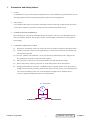
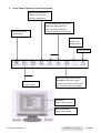
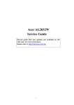
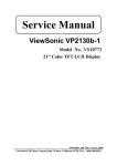
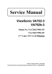
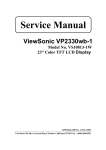
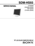
Service Manual ViewSonic VG700b-2 Model No. VLCDS24606-1W 17” Color TFT LCD Display (VG700b-2_SM_605 - Rev. 1b Feb. 2004) ViewSonic 381 Brea Canyon Road, Walnut, California 91789 USA - (800) 888-8583 Copyright Copyright ¤ 2003 by ViewSonic Corporation. All rights reserved. No part of this publication may be reproduced, transmitted, transcribed, stored in a retrieval system, or translated into any language or computer language, in any form or by any means, electronic, mechanical, magnetic, optical, chemical, manual or otherwise, without the prior written permission of ViewSonic Corporation. Disclaimer ViewSonic makes no representations or warranties, either expressed or implied, with respect to the contents hereof and specifically disclaims any warranty of merchantability or fitness for any particular purpose. Further, ViewSonic reserves the right to revise this publication and to make changes from time to time in the contents hereof without obligation of ViewSonic to notify any person of such revision or changes. Trademarks Optiquest is a registered trademark of ViewSonic Corporation. ViewSonic is a registered trademark of ViewSonic Corporation. All other trademarks used within this document are the property of their respective owners. Revision History Revision 1a Date 14/04/03 1b 02/10/04 ViewSonic Corporation Description Of Changes Initial Release DCN- 2661 Change Panel from QDI to LG by region DCN-4209 i Approval WANGJE Angela Luh Confidential – Do Not Copy VG700b-2 TABLE OF CONTENTS 1. Precautions and Safety Notices 1 2. Specification 2 3. Front Panel Function Control Description 3 4. Circuit Description 5 5. Adjusting Procedure 13 6. Trouble Shooting Flow Chart 17 7. Recommended Spare Parts List 20 8. Exploded Diagram And Spare Parts List 24 9. Block Diagram 26 10. Schematic Diagrams 27 11. PCB Layout Diagrams 34 ViewSonic Corporation ii Confidential – Do Not Copy VG700b-2 1. Precautions and Safety Notices 1. Caution : No modification of any circuit should be attempted. Service work should only be performed after you are thoroughly familiar with all of the following safety checks and servicing guide line. 2. Safety Check : Care should be taken while servicing this LCD display. Because of the high voltage used in the inverter circuit. These voltages are exposed in such areas as the associated transformer circuits. 3. POWER SUPPLY REQUIREMENTS The external power converter for this display utilizes AC and DC cords, AC cord is detachable, but DC cord is permanently attached. Any attempt to replace another adapter could result in serious problem on the display. 4. LEAKAGE CURRENT HOT CHECK 4-1 Plug the AC cord directly into the AC outlet. Do not use an isolation transformer during this check. 4-2 Connect a 1500 ohm, 10 watt resistor, paralleled by a 0.15uF capacitor between each metallic part and a good earth ground. 4-3 Use an AC voltmeter with 1000 ohm / volt or more sensitivity and measure the AC voltage across the combination 1500 ohm resistor and 0.15uF capacitor. 4-4 Move the resistor connection to each exposed metallic part and measure the voltage. 4-5 Reverse the polarity of the AC plug in the AC outlet and repeat the above measurement. 4-6 Voltage measured must not exceed 1.5 volt RMS, from any exposed metallic part to the ground. A leakage current tester may be used in the above hot check, in which case any circuit measured must not exceed 1.0 milliamp. In the case of a measurement exceeding the 1.0 milliamp value, a rework is required to eliminate the chance of a shock hazard. AC VOLTMETER V 0.15u . To Metal Parts ViewSonic Corporation 1500 10W 1 Earth Ground Confidential – Do Not Copy VG700b-2 2. Specification Mechanical: Dimension ( W x H x D ) mm Set: a. with stand b. Without stand 410.0 x 433 x 180 mm 410.0 x 433 x 58.4 mm Base (L X W) 290 x 180 mm Packing : ( W x H x D ) mm 472 x 515 x 216 mm Weight: Net / Gross ( Kg ) 4.5 / 6.9 Wall Mount (VESA) 100 x 100 mm LCD Panel type QDI / QD17EL07 Max. Resolution (HxV) 1280 x 1024 Nominal picture size (HxV 338 mm x 270 mm Display colors 16.2 M ( 6 bit + dithering) Dot pitch 0.264 mm Response time 4 +16 / 20ms (Tr + Tf / typical) Brightness (100% white) Typical: 300 cd/m² , Min. 240cd/m² Contrast Typical: 450:1, Min. 300:1 Viewing angle 75 / 75 /65 / 60 (L/R/T/B CR>=10) Synchronization Fh = 31~82 KHz / Fv=50~75Hz Presets 18 timing modes OSD Language 8 language Color Temperature sRGB , 6500°K (default) / 9300°K /5400°K / User R,G,B Plug & Play DDC1/2B interface Scalar chip Genesis gm2121 AD Audio Input Connector 3.5 mm Stereo, PC2001 Audio Amplifier 3W x 2 (chip :TPA3002D2) AC Power range 90 V ~ 264 V, 50 Hz / 60 Hz Power consumption < 48W green / < 3W amber (On / Off mode) ViewSonic Corporation 2 Confidential – Do Not Copy VG700b-2 3. Front Panel Function Control Description Displays the Main Menu or exits the control screen and saves adjustments. Scrolls through menu options and adjusts the displayed control. Also a shortcut to display the Temporarily silence Contrast adjustment control screen. audio output Power light Green = ON Orange=power Power On / Off Displays the control screen for the highlighted control. Also toggles Decreases or between two controls on some screens. increases volume Also a shortcut to auto image adjust Main Menu With On View controls Front Control Panel shown below in detail ViewSonic Corporation 3 Confidential – Do Not Copy VG700b-2 Main Menu Controls Adjust the menu items shown below by using the up and down buttons. A. Auto Image Adjust automatically sizes, centers, and fine tunes the video signal to eliminate waviness and distortion. Press the [2] button to obtain a sharper image. NOTE: Auto Image Adjust works with most common video cards. If this function does not work on your LCD display, then lower the video refresh rate to 60 Hz and set the resolution to its pre-set value. B. Contrast adjusts the difference between the image background (black level) and the foreground (white level). C. Brightness adjusts the lamps current to control the screen brightness. D. Audio Menu controls are explained below: Volume increases the volume, decreases the volume, and mutes the audio. Mute temporarily silences audio output. E. Color Adjust provides several color options: preset color temperatures and Custom User Color which allows you to adjust red (R), green (G), and blue (B). The factory setting for this product is 6500K (6500° Kelvin). 9300K — Adds blue to the screen image for cooler white (used in most office settings with fluorescent lighting). 5400K — Adds red to the screen image for warmer white and richer red. Custom User Color — Individual adjustments for red, green, and blue. 1 To select color (R, G or B) press button [2]. 2 To adjust selected color, press or . 3 When you are finished making all color adjustments, press button [1] twice. F. Information displays the timing mode (video signal input) coming from the graphics card in your computer. See your graphic card’s user guide for instructions on changing the resolution and refresh rate (vertical frequency). VESA 1280 x 1024 @ 60 Hz (recommended) means that the resolution is 1280 x 1024 and the refresh rate is 60 Hertz. G. Manual Image Adjust controls are explained below: H. Size (Horizontal Size) adjusts the width of the screen image. NOTE: Vertical size is automatic with your LCD display. H./V. Position adjusts horizontal and vertical position of the screen image. You can toggle between Horizontal and Vertical by pressing button [2]. Horizontal moves the screen image to the left or to the right. Vertical moves the screen image up and down. Fine Tune sharpens focus by aligning the illuminated text and/or graphic characters. Sharpness adjusts the clarity and focus of the screen image. Setup Menu controls are explained below: Language allows you to choose the language used in the menus and control screens. Resolution Notice displays the recommended resolution for this LCD display. Enable allows the Resolution Notice to appear on-screen. Disable will not allow the Resolution Notice to appear on-screen. OSD Timeout sets the length of time an on-screen display screen is displayed. For example, with a“15 second” setting, if a control is not pushed within 15 seconds, the display OSD disappears. H. OSD Position allows you to move the on-screen display menus and control screens. I. Memory Recall returns adjustments to the original factory settings if the display is operating in a factory Preset Timing Mode listed in this user guide. ViewSonic Corporation 4 Confidential – Do Not Copy VG700b-2 4. Circuit Description 4-1. Outline 1.1 POWER On/Off , LED, Button"2" , Up arrow- button , Down arrow button , Button"1" , button , Down arrow button , Button"1" , on the front panel. 1.2 Video signal connector, audio line-in receptacle and DC-IN are located on the back side of the cabinet. 1.3 OSD menu includes the following function; AUTO IMAGE ADJUST CONTRAST / BRIGHTNESS AUDIO MENU COLOR ADJUST INFORMATION MANUAL IMAGE ADJUST SETUP MENU MEMORY RECALL 1.4 CONTRAST and BRIGHTNESS can be directly controlled with UP / DN key. 1.5 Speaker out can be controlled with + / - volume key and MUTE key. 4-2. CONNECTORS 2.1 AC inlet : CEE22 typed connector 2.2 Audio : Line-in receptacle J1 1 2 3 PHONEJACK STEREO 1 6 2 7 3 8 4 9 5 10 2.3 Video signal connector 15P Mini D-Sub CN6 DB15HD 16 ViewSonic Corporation 15 14 12 13 11 17 PIN MNEMONI SIGNAL 1 RV Red Video 2 GV Green Video 3 BV Blue Video 4 NC None 5 GND Ground(DDC return) 6 RG Red GND 7 GG Green GND 8 BG Blue GND 9 +5V + 5V (for DDC) 10 SG Sync GND 11 NC None 12 SDA DDC Data 13 HS Horizontal Sync 14 VS Vertical Sync 15 SCL 5 ! DDC Clock Confidential – Do Not Copy VG700b-2 4-3. ELECTRICAL SPECIFIC ATIONS 3.1 Standard conditions Display area 338 x 270 Video signal 0.7 Vpp Contrast Max. Brightness Max. Ambient 20 +/- 5 C Input AC Warming up > 30 Display 1280 x1024 3.2 POWER 3.2.1 Power supply Input voltage 90~240 Volts Power frequency 50 / 60 Hz, +/-3 Hz Input current < 1.5 Arms @90Vac < 0.75Arms @265Vac Inrush current 90A(Max) at 230Vac Power consumption 48W(Max) Output Voltage 3.2.2 @0-4.8A Load 12Vdc+/- 5% Power Management State Power Indicator On 48Watts Green Standby <3Watts Amber Off <3Watts None 3.3 Acceptable timing If your timing is within following specification, this LCD display can automatically function with a certain position. Horizontal: Sync frequency: 30~81 kHz Vertical: Sync frequency: 56~75Hz 3.4 Signal level and input impedance 3.4.1 Video Signal level This LCD display is adjusted at the factory using 0, 7 Vp-p Video signal. 3.4.2 Sync Signal level H/V Separate: TTL level 3.4.3 Input impedance Video input: 75 ohms Sync input: > 1 k ohms ViewSonic Corporation 6 Confidential – Do Not Copy VG700b-2 State Power Indicator On 48Watts Green Standby <3Watts Amber Off <3Watts None 4-4. SIGNAL CABLE: Signal cable with Mini D-Sub 15P connectors at both ends . Length: 1.8 meter. 4-5. EDID data Analog EDID Time: 09:08:54 Date: Wed Sep 04, 2002 ______________________________________________________________________ ______________________________________________________________________ VIEWSONIC CORPORATION EDID Version # 1, Revision # 3 DDCTest For: VSC VG700b-2 ______________________________________________________________________ ______________________________________________________________________ 60 | 2A 40 30 70 13 00 52 0E 11 00 70 | 00 1E 00 00 00 FF 00 41 31 4B 80 | 30 33 30 31 30 30 30 30 31 0A 90 | 00 00 00 FD 00 32 4B 1E 52 0E 100 | 00 0A 20 20 20 20 20 20 00 00 110 | 00 FC 00 56 47 37 30 30 62 2D 120 32 0A 20 20 20 20 00 86 | _________________________________________________ ___________________ (08-09) ID Manufacturer Name = VSC (10-11) Product ID Code (Non-Alphanumerical) = B50B - (46347) (12-15) Last 5 Digits of Serial Number = NOT SPECIFIED (16) Week of Manufacture = 01 (17) Year of Manufacture = 2003 (10-17) Complete Serial Number = NOT SPECIFIED (18) EDID Structure Version Number = 1 (19) EDID Structure Revision Number = 3 (20) VIDEO INPUT DEFINITION : = Separate Sync, Analog signal, 0.700V/0.300V (1.000 Vp-p) (21) Maximum Horizontal Image Size = 340mm (22) Maximum Vertical Image Size = 270mm (23) Display Gamma = 2.20 (24) DPMS Supported Feature: = Active Off. Display type = RGB color display (25-34) ViewSonic Corporation CHROMA INFO: Red x = 0.633 Green x = 0.300 Blue x = 0.146 White x = 0.313 Red y = 0.336 Green y = 0.586 Blue y = 0.103 White y = 0.329 7 Confidential – Do Not Copy VG700b-2 (35) (36) (37) ESTABLISHED TIMING I: 720 x 400 @ 70Hz (VGA, IBM) 640 x 480 @ 60Hz (MAC II, Apple) 640 x 480 @ 67Hz (VESA) 640 x 480 @ 72Hz (VESA) 640 x 480 @ 75Hz (VESA) 800 x 600 @ 56Hz (VESA) 800 x 600 @ 60Hz (VESA) ESTABLISHED TIMING II: 800 x 600 @ 72Hz (VESA) 800 x 600 @ 75Hz (VESA) 832 x 624 @ 75Hz (MAC II, Apple) 1024 x 768 @ 60Hz (VESA) 1024 x 768 @ 70Hz (VESA) 1024 x 768 @ 75Hz (VESA) 1280 x 1024 @ 75Hz (VESA) Manufacturer's Reserved Timing: 1152 x 870 @ 75Hz (38-53) (MAC II, Apple) Standard Timing Identification: #1: 1280 x 1024 @ 60Hz #2: (40) not specified #3: (42) not specified #4: (44) not specified #5: (46) not specified #6: (48) not specified #7: (50) not specified #8: (52) not specified (54-71) Detail Timing Description #1: 1280x1024 Pixel Clock=108.0MHz --------------------------------------------------------------------------------------------------------------------------------------------------------------Horizontal Image Size=338mm Vertical Image Size=270mm Refresh Mode: Non-Interlaced Normal display, no stereo HORIZONTAL: Active Time = 1280 pixels Blanking Time = 408 pixels Sync Offset = 48 pixels Sync Pulse Width = 112 pixels Border = 1 pixels ViewSonic Corporation Frequency = 64.0 kHz ! 8 Confidential – Do Not Copy VG700b-2 VERTICAL: Active Time = 1024 lines Blanking Time = 42 lines Sync Offset = 1 lines Sync Pulse Width = 3 lines Border = 0 lines Frequency = 60.0 Hz Sync configuration: Digital separate, V(+), H(+) (72-89) Monitor Description: --------------------------------------------------------------------------------------------------------------------------------------------------------------Monitor S/N: A1K030100001 (90-107) Monitor Description: --------------------------------------------------------------------------------------------------------------------------------------------------------------Monitor Range Limits: Vertical Frequency (min) = 50Hz Vertical Frequency (max) = 75Hz Horizontal Frequency (min) = 30Hz Horizontal Frequency (max) = 82Hz Maximum Supported Pixel Clock = 140MHz (108-125) Monitor Description: --------------------------------------------------------------------------------------------------------------------------------------------------------------Monitor Name: VG700b-2 (127) Checksum OK 4-6. THEORY OF OPERATION This section describes the function of the LCD monitor per functional block. This monitor includes MB board, inverter board, adapter and button board. 1.1 MB BOARD The MB board is a four-layer, single-landed design with ground and internal planes provided. DC power from the power adapter enters the board through the DC jack. Other connectors on the board are for inverter, audio and button board .The VGA cable is a signal cable that contains video signal, sync signal and DDC signal from PC VGA adapter. This system board consists of 4 functional areas: flat panel controller, flash ROM, power regulator and Audio amplifier 1.2 Flat panel controller… gm2121 (U2) The heart of the system board is Genesis gm2121. The gm2121 is a graphics processing IC for LCD monitor. It provides all key IC functions required for LCD panel. On-chip functions include a high-speed triple-ADC, PLL, high scaling engine, OSD controller and on-chip micro ! controller. ViewSonic Corporation 9 Confidential – Do Not Copy VG700b-2 a) Clock Generation : Crystal Input Clock (TCLK and XTAL). This is the input pair to an internal crystal oscillator and corresponding logic. A 14.318 MHz crystal is recommended. b) Hardware Reset ( Pin 17): Hardware Reset signal is generated by MAX6326 (U5).It asserts a reset signal for at least 100 ms. c) Analog to Digital Converter: The gm2121 chip has three ADC's (analog-to-digital converters), one for each color (red, green and blue) .The analog RGB signals are connected to gm2121 as described below d) OSD: The gm2121 has a fully programmable, high-quality OSD controller. The on-chip static RAM (4096 words by 24 bits) stores the cell map and the cell definitions. e) On-Chip Micro controller (OCM): The gm2121 on-chip micro controller (OCM) serves as the system micro controller. That is, it programs the gm2121 and manages other devices in the system such as the keypad, the backlight, LED, audio and non-volatile RAM. Using general purpose input/output (GPIO) pins. ViewSonic Corporation 10 Confidential – Do Not Copy VG700b-2 f) Panel Power Sequencing ( PPWR, PBIAS) ( Pin 40~41) : The gm2121 has two dedicated outputs PPWR and PBIAS ( Pin113 and Pin114) to control LCD power sequencing once data and control signals are stable. g) Parallel ROM Interface Port (Pin 1~6, Pin 139~160: The gm2121 has parallel ROM interface port, Pin139~156 for address bus, pPin1~6, Pin159 and Pin160 for data bus. h) Panel interface (Pin 48~57, Pin64~73): The gm2121 driver interface is highly programmable. It supports dual bus / dual port for SXGA drivers. 1.3 Power Regulator AIC1563 (U6), LT1117 (U7, U8): The AIC1563 is a monolithic control IC containing the primary functions required for DC to DC converters. The device consists of an internal temperature compensated reference, comparator, controlled duty cycle. Oscillator with an active current sense circuit. Desired output voltage is determined by the equation, Volt = 1.25 (1 + R104 / R103), In this case, the output voltage is 5 Volts The AIC1117 is a low dropout positive adjustable regulator with minimum of 1A output current capability, so it is well suited for 3.3 V and 2.5 V Regulator. U6 is a 2.5 V regulator, desired output voltage is determined by the equation. Volt=1.25 x (1 + R93/R92) = 2.5, U5 is a 3.3 V regulator, desired output voltage is determined by the equation Volt=1.255 x (1+ R95/R94) = 3.3 1.4 Audio Amplifier TPA3003D2 (U1) The TPA3003D2 is a class D, 2 channel audio power amplifier capable of delivering 3W of continuous average power to 8 ohms with less than 1% (THD) from a 12 V power supply. TPA3003D2 can directly drive 8 ohms speaker, and does not require output coupling capacitor, bootstrap capacitor, or LC filter. Audio line-in is fed into pin 2, 6 of the TPA3003D2. The output gain is controlled by pin 11. 1.5 Inverter Board This is a specific inverter for L7VB monitor backlight which converters 12 Vdc to drive four cold cathode fluorescence tubes. Electrical specification described as below. ViewSonic Corporation 11 Confidential – Do Not Copy VG700b-2 1.6 Adapter This is a general purpose AC / DC adapter which converts 90~240 Vac to a stabilized DC, 12V with rated output current of 4.16A. Electrical specification described as below. ViewSonic Corporation 12 Confidential – Do Not Copy VG700b-2 5. Adjusting Procedure OSD Function Menu 5-1. Main Menu Press “1” Button (Menu Button) to enter Main Menu: Press Up Button to the previous page or Down Button to the next page. Press “1” Button to exit Main Menu. (1) Auto Image Adjust Page: Press “2” Button to do auto image adjust function. Press “1” Button to exit the page. (2) Contrast/Brightness Page: Press “2” Button to enter Contrast Item. Press “1” Button to exit the page. 1) Contrast Item Press up Button to make contrast high. Press down Button to make contrast low. Press “2” Button to enter Brightness Item. Press “1” Button to exit the item. 2) Brightness Item Press Up Button to make brightness high. Press Down Button to make brightness low. Press “2” Button to enter Contrast Item. Press “1” Button to exit the item. (3) Color Adjust Page: Press “2” Button to enter Color Adjust page. Press “1” Button to exit the page. Press Up Button to the previous item or Down Button to the next item. 1) sRGB Item 2) 9300K Item 3) 6500K Item 4) 5400K Item Press “2” Button to select current Item. Press “1” Button to exit current item. 5) User Color Item Press “2” Button to enter User Color item. Press “1” Button to exit User Color item. Red, Green, Blue Options: Press “2” Button to switch among the options. Press “1” Button to exit the options. Press Up Button to make current option high. Press Down Button to make current option low. (4) Information Page: Press “2” Button to show the information. Press “1” Button to exit Information page. (5) Manual Image Adjust Page: Press “2” Button to enter Manual Image Adjust page. Press “1” Button to exit Manual Image Adjust page. ViewSonic Corporation 13 Confidential – Do Not Copy VG700b-2 Press Up Button to the previous item or Down Button to the next item. 1) H./V. Position Item Press “2” Button to enter H./V. Position item. Press “1” Button to exit H./V. Position item. a) Horizontal Position Option: Press “2” Button to enter the Vertical Position option. Press “1” Button to exit Horizontal Position option. Press Up Button to make current option high. Press Down Button to make current option low b) Vertical Position Option: Press “2” Button to enter the Horizontal Position option. Press “1” Button to exit Vertical Position option. Press Up Button to make current option high. Press Down Button to make current option low 2) Horizontal Size Item Press “2” Button to enter Horizontal Size item. Press “1” Button to exit Horizontal Size item. Press Up Button to make current item high. Press Down Button to make current item low. 3) Fine tune Item Press “2” Button to enter Fine tune item. Press “1” Button to exit Fine tune item. Press Up Button to make current item high. Press Down Button to make current item low. 4) Sharpness Item Press “2” Button to enter Sharpness item. Press “1” Button to exit Sharpness item. Press Up Button to make current item high. Press Down Button to make current item low. (6) Setup Menu Page: Press “2” Button to enter Setup Menu page. Press “1” Button to exit Setup Menu page. Press Up Button to the previous item or Down Button to the next item. 1) Language Select Item Press “2” Button to enter Language Select item. Press “1” Button to exit Language Select item. Press Up Button to the previous option or Down Button to the next option. English, French……..Option Press “2” Button to select the language. Press “1” Button to exit the option. 2) Resolution Notice Item Press “2” Button to enter Resolution Notice item. Press “1” Button to exit Resolution Notice item. ViewSonic Corporation 14 Confidential – Do Not Copy VG700b-2 Enable, Disable Option Press “2” Button to select the option. Press “1” Button to exit the option Press Up Button to the previous option or Down Button to the next option. 3) OSD Position Item Press “2” Button to enter OSD Position item. Press “1” Button to exit OSD Position item. a) Horizontal Position Option Press “2” Button to enter the Vertical Position option. Press “1” Button to exit Horizontal Position option. Press Up Button to make current option high. Press Down Button to make current option low b) Vertical Position Option: Press “2” Button to enter the Horizontal Position option. Press “1” Button to exit Vertical Position option. Press Up Button to make current option high. Press Down Button to make current option low 4) OSD Time Out Item Press “2” Button to enter OSD Time Out item. Press “1” Button to exit OSD Time Out item. Press Up Button to make OSD time out long. Press Down Button to make OSD time out short. 5) OSD Background Item Press “2” Button to enter OSD Background item. Press “1” Button to exit OSD Background item. Enable, Disable Option Press “2” Button to select the option. Press “1” Button to exit the option. Press Up Button to the previous option or Down Button to the next option. (7) Memory Recall Page Press “2” Button to do the memory recalls function. Press “1” Button to exit the page. 5-2. Other Menu: (1) Contrast Dialog Press Down Button to enter the Contrast Dialog. Press “1” Button to exit the Contrast Dialog. Press “2” Button to enter the Brightness Dialog. Press Up Button to make contrast high. Press Down Button to make contrast low. (2) Brightness Dialog ViewSonic Corporation 15 Confidential – Do Not Copy VG700b-2 Press Down Button to enter the Brightness Dialog. Press “1” Button to exit the Brightness Dialog. Press “2” Button to enter the Contrast Dialog. Press Up Button to make brightness high. Press Down Button to make brightness low. (3) Volume Dialog Press Left Button or Right Button to enter the Volume Dialog . Press “1” Button to exit the Volume Dialog. Press Left Button to make volume low. Press Right Button to make volume high. (4) Mute Dialog Press Mute Button to switch mute to volume or volume to mute. (5) Auto Image Adjust Dialog Press “2” Button to do the auto image adjusts function. ViewSonic Corporation 16 Confidential – Do Not Copy VG700b-2 6. Trouble Shooting Flow Chart 6.1 No power No Power Power Cord OK? Change Power Cord Adaptor OK? 12V OK? Change Adaptor Fuse1, L16, L17, CN6 Open? Change open component Change open component +5V OK? L18, L19, D3, Q7, R68 OK? Change U6 +3.3V OK? L21, R71, R73 OK? Change NG component Change U8 or Check U2 +2.5V OK? L20, R70, R72 OK? Change NG component Change U7 or check U2 ViewSonic Corporation 17 Confidential – Do Not Copy VG700b-2 6.2 Always show NO SIGNAL No signal NG Change VGA Cabl e Check VGA Cable OK NG Change CN7 Check CN7 OK NG Change NG component Check H,V syncinput circuit OK Change U2 6.3 Missing color Color abnomal NG Change VGA Cable Check VGA Cable OK NG Change CN7 Check CN7 Change U2 OK NG Change NG component OK Check RGB input circuit OK NG Check Panel NG Change NG component Check LVDS out put circuit Change Panel OK OK NG Change CN5 ViewSonic Corporation OK Check LCD Cable Check CN5 18 NG Change LCD Cable Confidential – Do Not Copy VG700b-2 6.4 White screen White Screen NG Change LCD Cable Check LCD cable OK NG Change CN5 Check CN5 OK NG Change NG component Check L22, Q9 OK NG Change NG component Check Q10, R98, R76 OK NG Change U2 OK Check U2 Change Panel 6.5 No Audio No Audio No Change Q6 Check U1 Pin 1=0V? Yes Yes Change Q3 Check U1 Pin 11= 0V? No Yes Change L3 L3 open? No Yes Change L8 Change U1 Check L8 Open? Yes No Yes No Change NG component ViewSonic Corporation Check C35, R42 OK? Check U1 Pin 16, 17, 20, 21, 40, 41, 44, 45 Short? 19 NO Change speaker Confidential – Do Not Copy VG700b-2 7. Recommended Spare Parts List VG700b-2 Recommended Spare Parts List Item 1 2 3 4 5 6 7 8 9 10 a 10 b 11 12 13 14 15 16 17 18 19 20 ViewSonic P/N B-IF-0222-0050 B-SB-0221-0568 P-BX-0601-0898 P-FM-0602-0542 P-FM-0602-0543 M-MS-0808-8981 M-MS-0808-9232 A-CD-VG700B-2-B C-BC-0302-0543 M-CV-0830-2371 C-FP-0301-0969 M-CV-0830-2377 M-SCW-0824-0795 M-LCD-0826-0213 A-AD-0114-0205 E-FS-0410-0108 A-PC-0106-0224 M-LCD-0824-0181 C-BC-0302-0475 C-BS-0303-0393 B-IF-0222-0051 ViewSonic Corporation Ref. P/N 21L7VSB0021 AS022172502 HFL7V004016 HBL7V001013 HBL7V002010 HAL7V001012 FCL7V010013 HGL7V006010 37L7VBCVS11 36L7VRCVS05 36L7VRCVS05 EBL7V006015 MM40080BCI5 AA17EL01001 AG12042CK00 DK400WFU001 DM333181G97 AA170E01001 EAL7V003015 35L7VSAVS16 31L7VSS0016 Description scaler Board Inverter Carton Polyform (right) Polyform (left) EPE bag ID label CD wizard Rear enclosure Front enclosure Front enclosure Base Screw ( To assembly the cabinet) LCD panel Adapter Fuse POWER CORD 3P 1.8M(USA)V04VS35001218000 LCD(TFT) LM170E01 A5 17"SVGA BACK COVER(EAL7V003,REV3A) L7VB STAND ASSY L7VB SCALAR/B S/S ASSY 20 Location Universal number# Q'ty 1 1 1 1 1 1 1 1 1 1 1 1 12 LG LM170E01-A5 1 ADP-50GH BB 1 1 1 AA170E01001 Confidential – Do Not Copy VG700b-2 VG700b-2 BOM Parts List Item 1 2 3 4 5 6 7 8 9 10 11 12 13 14 15 16 17 18 19 20 21 22 23 24 25 26 27 28 ViewSonic P/N #N/A B-IF-0222-0050 B-IF-0222-0051 #N/A #N/A E-IC-0401-2651 E-IC-0401-2652 #N/A E-IC-0401-2653 E-IC-0401-2654 #N/A E-IC-0401-2655 #N/A #N/A #N/A E-Q-0402-1580 E-Q-0402-1582 E-D-0403-2082 E-D-0403-2083 E-D-0403-2084 E-D-0403-2085 #N/A #N/A #N/A #N/A #N/A #N/A #N/A Ref. P/N 1L7VZZZVS78 21L7VSB0021 31L7VSS0016 AJ02121^C15 AKE1B8APN03 AKE3A8S0Y01 AKE3D8Q0A00 AKE3D8S0Y11 AL001117078 AL001563001 AJ030030H03 AL006326007 BA039040Z01 BA039060Z01 BAM23010Z05 BAM9410YZ02 BAN70020T04 BC1SS355Z05 BCAN202UZ01 BCRB081LZ02 BD05232BZ09 CH00506J904 CH04706J902 CH11206J908 CH12206J901 CH21006K917 CH22206K917 CH31006K919 Part Description L7VB LCD MONITOR (LG) EUROPE L7VB SCALAR/B ASSY (LG) L7VB SCALAR/B S/S ASSY IC(160P) GM2121_AD (162MHZ,PQFP) IC(32P) FLASH ROM W39F010P-70B(PLCC) IC,EEPROM(8P) 24LC16B/SN(2K*8,100KHZ) IC EEPROM(8P)AT24C21-10SI-2.5(128*8,10NS IC,EEPROM(8P) 24LC21A/SN(128*8,100KHZ) IC(3P) AIC1117CY(SOT-223) IC(8P) AIC1563CS(SOP8) IC(48P)TPA3003D2PFB(TQFP) IC(3P) MAX6326UR29(SOT23) TRANSISTOR,SMD MMBT3904(40V,200MA) TRANSISTOR,SMD MMBT3906(40V,200MA) TRANSISTOR MOSFET SI2301DS(-12V,-2.3A) TRANSISTOR MOSFET SI9410DY(30V,7A) TRANSISTOR MOSFET 2N7002(60V,0.115A) DIODE SMD 1SS355(80V,100MA) DIODE,SMD DAN202U(80V,100MA,SMD) DIODE SMD RB081L-20(20V,5.0A,VF:0.45V) DIODE,ZENER,SMD MMBZ5232B(5.6V,SOT23) CAPACITOR CHIP 5P,50V(+-5%,NPO,0603) CAPACITOR CHIP 47P 50V(+-5%,NPO,0603) CAPACITOR CHIP 120P 50V(+-5%,NPO,0603) CAPACITOR CHIP 220P 50V(+-5%,NPO,0603) CAP CHIP 1000P 50V(+-10%,X7R,0603) CAP CHIP 2200P 50V(+-10%,X7R,0603) CAP CHIP 0.01U 50V(+-10%,X7R,0603) 29 #N/A CH41004Z931 CAP CHIP 0.1U,25V(+80-20%,Y5V,0603) 30 31 32 33 34 35 #N/A #N/A #N/A #N/A #N/A #N/A CH51004MA32 CS00003J900 CS00006J205 CS04703J906 CS05603F903 CS07503J907 CAPACITOR CHIP 1UF 25V(+-20%,Y5V,0805) RESISTOR CHIP 0 1/10W+-5%(0603) RESISTOR CHIP 0 1/4W+-5%(3216) RES CHIP 47 1/10W +-5%(0603) RES CHIP 56 1/10W +-1%(0603) RES CHIP 75 1/10W +-5%(0603) 36 #N/A CS02203J902 RES CHIP 22 1/10W +-5%(0603) 37 38 39 40 41 42 #N/A #N/A #N/A #N/A #N/A #N/A CS12003F905 CS13303F909 CS15103J909 CS21003F904 CS23003F900 CS24703J900 RESISTOR CHIP 200 1/10W+-1%(0603) RESISTOR CHIP 330 1/10W +-1%(0603) RESISTOR CHIP 510 1/10W +-5%(0603) RESISTOR CHIP 1K,1/10W,+-1%(0603) RES CHIP 3K 1/10W +-1%(0603) RES CHIP 4.7K 1/10W +-5%(0603) 43 #N/A CS31003J908 RES CHIP 10K 1/10W +-5%(0603) 44 45 46 47 48 #N/A #N/A #N/A #N/A #N/A CS34703J901 CS41203F905 CS42403F905 CS43303J906 CS11003J904 RES CHIP 47K 1/10W +-5%(0603) RES CHIP 120K 1/10W +-1%,0603 RESISTOR CHIP 240K 1/10W,+-1%(0603) RES CHIP 330K 1/10W +-5%(0603) RESISTOR CHIP 100 1/10W +-5%(0603) 49 #N/A CX0P121R000 EMI FILTER CHIP HI1206P121R-00(120 6A) 50 51 52 53 54 55 56 57 58 59 60 61 62 63 64 #N/A M-MS-0808-7699 E-FS-0410-0108 #N/A #N/A #N/A E-D-0403-2142 #N/A E-X-0415-0128 #N/A #N/A #N/A E-C-0404-4904 #N/A M-MS-0808-7693 DAL7VBMB4E6 DGP320001Z0 DK400WFU001 CS14703J908 CS41003F908 CS25603J909 BC000S1AZ08 BC011FS2A01 BG614318D55 CC62204MD23 CC71004MD68 CC73303MD51 CC81001MD71 DFDS15FR050 DFHD04MR124 PCB(M/B) L7VB MB (4L,155*115, REVE) IC SOCKET,SMD PLCC 32P(LOW PROFILE,SMD) FUSE SMD 4A/32V,FAST(UL/CSA,3216) RESISTOR CHIP 470 1/10W+-5%(0603) RESISTOR CHIP 100K 1/10W+-1%(0603) RES CHIP 5.6K 1/10W +-5%(0603) DIODE SMD S1A(35V,1A,SMA) DIODE EC11FS2(200V,1A,FAST) XTAL DIP 14.318MHZ(+-30PPM,07010-X-136-2 CAP ELEC 22U 25V(+-20%,105C,5*11,2000HR) CAP ELEC 100U 25V +-20%,105C,6*11,LESR CAP ELEC 330U 16V(+-20%,105C,8*11,2000HR CAP ELEC DIP 1000U6.3V +-20% 105C 8*11.5 CONN D-SUB 15P 3R FR,P1.15,H12.55,NO SRW CONN DIP HEADER 4P 1R MR(P2.0,H4.1) ViewSonic Corporation 21 Location Universal number# U2 U4 U5 U9 U9 U7,U8 U6 U1 U3 Q6,Q10 Q4,Q5,Q8 Q9 Q7 Q2,Q3 D1,D2 D4 D3 D5,D6,D7,D8 C70,C71 C113,C114 C92 C20,C21,C22,C23,C35 , C54 , C81 C16,C17,C43,C44,C95 C94 C24,C25,C38,C39 ,C107, C108 ,C112,C109,C110,C111 C1,C5,C6,C7,C8,C9,C10,C11,C12 C13,C14,C18,C19,C31,C34,C37 , C79 C41,C42,C46,C47,C48,C49,C50 , C75 , C76 , C77 C51,C52,C53,C56,C57,C58,C59 , C72 , C73 , C74 C60,C61,C62,C64,C65,C66,C67 , C68, C69,C70 , C71 C80,C85,C86,C88,C89,C91,C96 C103,C105,C106,C115 C3,C4,C26,C27,C28,C29,C30,C33,C36,C87,C102 R6,R94,R97 R63 R64 R81,R84,R86 R88,R89,R90 R22,R23,R24,R25,R26,R27,R28,R30,R32,R33,R49,R50 R80,R82,R85,R93,R95 R70,R71,R72 R73 R96 R67,R69 R68 R35,R37,R44,R76,R98 R1,R2,R3,R5,R7,R8,R9,R10,R11,R12,R13,R14,R16 R18 , R18 , R20 , R40 , R41 , R43 , R46 , R54 , R55 R56 , R57 , R58 , R59 , R60 , R61 , R62 , R78 , R79 R21,R74,R77 R42 R66 R65 R83,R87,R91,R99,R100 L1,L2,L3,L4,L5,L6,L7,L8,L9,L10,L11,L12,L13,L14, L15,L17,L19,L21,L22 U4 FUSE1 R29,R31 R38,R39 R34,R36 D9 D9 X1 C15,C32,C40,C45,C55,C63,C72,C78 C98,C99,C100,C101 C2,C90,C104 C97 CN7 CN4 Confidential – Do Not Copy Qty 1 1 1 1 1 1 1 2 1 1 1 2 3 1 1 2 2 1 1 4 2 2 1 7 5 1 10 56 11 3 1 1 3 3 17 3 1 1 2 1 5 31 3 1 1 1 5 19 1 1 1 2 2 2 1 1 1 8 4 3 1 1 1 VG700b-2 Item 65 66 67 68 69 70 71 72 73 74 75 76 77 78 79 80 81 82 83 84 85 86 87 88 89 90 91 92 93 94 95 96 97 98 99 100 101 102 103 104 105 106 107 108 109 110 111 112 113 114 115 116 117 118 119 120 121 122 123 124 125 126 127 128 129 130 131 132 133 134 135 136 137 138 ViewSonic P/N M-MS-0808-7694 M-MS-0808-7695 #N/A M-MS-0808-7697 M-MS-0808-7698 E-L-0407-1562 E-L-0407-1563 #N/A #N/A C-FP-0301-0969 M-MS-0808-8718 M-MS-0808-8719 M-MS-0808-8985 C-BC-0302-0543 C-BC-0302-0475 M-CV-0830-2484 M-SCW-0824-0725 M-BK-0805-0024 M-MS-0808-7709 M-LCD-0826-0213 M-SCW-0824-6761 M-SCW-0824-0728 M-SCW-0824-0795 M-SCW-0824-6760 C-FP-0301-0282 C-FP-0301-0759 M-MS-0808-7707 M-LB-0813-0744 E-SK-0412-0066 M-MS-0808-7700 #N/A #N/A #N/A M-MS-0808-8987 M-BK-0805-0025 M-MS-0808-7701 M-MS-0808-7702 #N/A M-LB-0813-0893 M-BK-0805-0026 M-MS-0808-8988 M-MS-0808-8989 M-MS-0808-8991 E-SK-0412-0067 M-SCW-0824-0727 M-CV-0830-2372 M-SCW-0824-0725 M-MS-0808-8986 M-MS-0808-8990 M-MS-0808-8984 M-MS-0808-8983 M-MS-0808-9232 M-LB-0813-0894 M-MS-0808-8994 #N/A C-BS-0303-0393 M-CV-0830-2376 M-CV-0830-2377 M-MS-0808-8992 M-MS-0808-8993 PL-PD-0714-0080 PL-PD-0714-0081 PL-PD-0714-0082 M-SCW-0824-0727 #N/A M-SCW-0824-0725 A-AD-0114-0205 B-SB-0221-0568 A-VC-0101-0294 #N/A M-FC-0809-0778 M-FC-0809-0779 A-PC-0106-0227 M-MS-0808-9208 Ref. P/N DFHD06MR093 DFHD11MR043 DFHD30MS531 DFPJ03MR140 DFPJ05FR137 CWK5BR6H019 DC04725K002 AZL7VBI0000 22L7VLAVS24 36L7VRCVS05 EBL7V003016 EBL7V007011 GBL7V001013 37L7VBCVS11 EAL7V003015 FBL7V007011 MF30050IBJ6 FBL7V021014 GAL7V004011 AA17EL01001 MM30030IBJ4 MM30050IBJ3 MM40080BCI5 MS30060IM18 33L7VFBVS02 EAL7V001012 FEL7V001016 HCL7V001014 34L7VSAVS07 EAL7V002019 EAL7V002001 RC00R950007 RJ0000R2001 FBL7V020018 FBL7V016011 EBL7V001013 EBL7V002010 3AL7VLBVS02 FCL7V007012 FBL7V017017 FBL7V018013 FBL7V019010 FBL7V022011 DN0QT110003 MF30080IBJ0 EBL7V005019 MF30050IBJ6 MBLI1004018 FBL7V026016 FCL70004010 MBL7V006015 FCL7V010013 HCL7V005010 GBL7V004012 23L7VCSVS52 35L7VSAVS16 EBL7V004012 EBL7V006015 FBL7V027012 FBL7V024013 GAL7V001012 GAL7V002019 GAL7V003015 MF30080IBJ0 MM40080ICI0 MF30050IBJ6 AG12042CK00 AS022172502 DD0L7VPC103 DD0L7VPC201 DDL7VBSP005 DDL7VBTH000 DM333181801 24L7VPKVS20 ViewSonic Corporation Part Description CONN DIP HEADER 6P 1R MR(P2.5,H4.1) CONN DIP HEADER 11P 1R MR(P1.5,H4.1) CONN DIP HEADER 30P 2R MS(P2.0,H4.0) CONN POWER JACK 3P MR CONN DIP PHONE JACK 5P FR(H10) FERRITE CORE K5B R6H 6*10*0.85-2TS-B CHOKE COIL 47UH(2.5A,+-10%,T07473) L7VB SW BIOS IMAGE(LG PANEL) L7VB LCD MODULE ASSY(2ND PANEL) L7VB LOGO REAR COVER ASSY LOGO PLATE(EBL7V003,REV3A) LOGO REAR COVER(EBL7V007,REV3A) SPONGE PAD L7V(GBL7V001,REV3A) L7VB BACK COVER ASSY BACK COVER(EAL7V003,REV3A) KENSINGTON CAP(FBL7V007,REV3A) SCREW F3*5-I(NI) VESA METAL L7VB(FBL7V021,REV3A) RUBBER PAD REAR(GAL7V004,REV3A) LCD(TFT) LM170E01 A5 17"SVGA SCREW M3*3-I-NI SCREW M3.0*5.0-I(NI) SCREW M4.0*8-B(NI,NYLOK) SCREW F3*6-I(NI) L7V FRONT BEZEL ASSY FRONT BEZEL(EAL7V001 ,REV3A) LOGO FRONT(FEL7V001,REV3A) LOGO LABEL(HCL7V001,REV3A) L7V SPEAKER ASSY SPACKER BEZEL L7V(EAL7V002,REV3A) SPEAKER BEZEL (EAL7V002,REV.3A) PAINT P-COAT BLACK OR950 L7V THINNER PLASTIC COAT OR2 PANEL HOLD UPPER R L7VB(FBL7V020,REV3A) LCD BKT MIDDLE L7VB(FBL7V016,REV3A) BUTTON KEY L7V (EBL7V001,REV3A) LED LENS(EBL7V002,REV3A) L7VB LCD BKT LOWER ASSY MYLAR COSMETIC L7VB(FCL7V007,REV3B) LCD BKT LOWER L7VB(FBL7V017,REV3B) PANEL HOLD UPPER L L7VB(FBL7V018,REV3A) PANEL HOLD L7VB(FBL7V019,REV3A) I/V SHIELDING L7VB(FBL7V022,REV3A) SPEAKER ASSY L7V FG-QT110 3W*2 SCREW F3.0*8-I(NI) NECK BACK COVER L7V(EBL7V005,REV3A) SCREW F3*5-I(NI) IO NUT LI1(MBLI1004,REV3A) ALUMINUM FOIL L7VB(FBL7V026,REV3A) LCD MYLAR L70L-E(FCL70004,REV3A) STAND OFF L7VB (MBL7V006,REV3A) TAPE FOR CABLE L7VB LG(FCL7V010,REV3A) WARNING LABEL, INVERTOR(HCL7V005,3A) GASKET L7VB (GBL7V004,REV3B) L7VB CHISSIS ASSY (EU POWER CODE) L7VB STAND ASSY NECKFRONT COVER L7V(EBL7V004,REV3A) STAND BOTTOM COVER L7V(EBL7V006,RVE3A) HINGE ASSY L7VB(FBL7V027,REV3A) STAND PLATE L7VB(FBL7V024,REV3A) RUBBER FOOD F(GAL7V001,REV3A) RUBBER FOOD L(GAL7V002,REV3A) RUBBER FOOD R(GAL7V003,REV3A) SCREW F3.0*8-I(NI) SCREW M4.0*8.0-I(NI)-NYLOK SCREW F3*5-I(NI) ADP 12V 4.2A ADP-50GH BB 100~240V 1A1A INV MODULE(TDK)L7VB(12V,V=720V,I=7MA,A1A CABLE ASSY L7V MB-VGA(15/15P,REV1A) CABLE ASSY L7V1.8M PC-MONITOR (REV3A) CABLE ASSY L7VB SPEAKER (4P,REV2A) CABLE ASSY L7VB MB-BUTTON (11P,REV2A) POWER CORD SP-023+IS-14H05VV-F3P 1.8M EU L7VB PACKING ASSY (2ND PANEL) 22 Location CN1 CN2 CN5 CN6 CN3 L16 L18 Universal number# Confidential – Do Not Copy Qty 1 1 1 1 1 1 1 1 1 1 1 1 1 1 1 1 5 1 4 1 2 13 8 12 1 1 1 1 1 1 1 1 1 1 1 1 1 1 1 2 1 1 3 1 5 3 2 2 1 1 1 1 1 1 1 1 1 1 1 1 1 2 2 3 4 4 1 1 1 1 1 1 1 1 VG700b-2 Item 139 140 141 142 143 144 145 146 147 148 149 150 151 152 153 154 155 ViewSonic P/N M-FC-0809-0777 M-FC-0809-0795 #N/A M-MS-0808-8981 P-FM-0602-0542 P-FM-0602-0543 M-LB-0813-0747 A-CD-VG700B-2-B P-BX-0601-0898 #N/A M-LB-0813-0745 M-LB-0813-0746 B-SB-0221-0503 #N/A PL-BT-0706-0126 M-MS-0808-7695 PL-BT-0706-0127 Ref. P/N DDL7VBIV005 DDL70LLC201 FCL7V002011 HAL7V001012 HBL7V001013 HBL7V002010 HCL7V004013 HGL7V006010 HFL7V004016 HFL7V002013 HCL7V002011 HCL7V003017 32L7VBB0009 BEYG0013DA3 DA0L7VTB2A1 DFHD11MR043 DHP0002B108 ViewSonic Corporation Part Description CABLE ASSY L7VB INVERTER(6P,REV2A) CABLE ASSY L70L MB-LCD(30P,REV2A)FOR LG FILM BEZEL (FCL7V002,REV3A) EPE BAG L7V(HAL7V001,REV3A) END CAP R L7V(HBL7V001,REV3A) END CAP L L7V(HBL7V002,REV3A) CORE LABEL(HCL7V004,REV3A) USER MANUAL&CD L7VB-LG(HGL7V006,REV3A) CARTON L7VB(HFL7V004,REV3A) COVER CARTON(HFL7V002,REV3A) SERIAL LEBAL(HCL7V002,REV3A) CARTON LEBAL(HCL7V003,REV3A) L7V BUTTON/B ASSY LED(DIP) YELLOW/GREEN(L-3WYGW) PCB(BUTTON)L7V TB(2L,190*17,REVA) CONN DIP HEADER 11P 1R MR(P1.5,H4.1) SWITCH PUSH BUTTON(PT-002-B1,50MA,12V 23 Location Universal number# LED1 CN1 SW1,SW2,SW3,SW4,SW5,SW6,SW7,SW8 Confidential – Do Not Copy Qty 1 1 1 1 1 1 1 1 1 0.05 1 1 1 1 1 1 8 VG700b-2 8. Exploded Diagram And Spare Parts List 14 31 ViewSonic Corporation 24 Confidential – Do Not Copy VG700b-2 VG700b-2 Exploded Parts List Item 1 2 3 4 5 6 7 8 9 10 11 12 13 14 15 16 17 18 19 20 21 22 23 24 25 26 27 28 29 30 31 32 33 34 35 36 37 38 39 40 41 42 43 44 45 46 47 48 49 ViewSonic P/N C-BC-0302-0475 M-CV-0830-2484 M-LCD-0826-0213 M-BK-0805-0024 M-MS-0808-7709 M-SCW-0824-0728 M-SCW-0824-6759 M-SCW-0824-6760 M-SCW-0824-6761 M-MS-0808-8986 M-MS-0808-8987 M-BK-0805-0025 M-BK-0805-0026 M-MS-0808-8988 M-MS-0808-8989 M-MS-0808-8990 M-MS-0808-8991 M-MS-0808-7706 E-SK-0412-0081 M-SCW-0824-6758 M-CV-0830-2372 M-CV-0830-2376 M-CV-0830-2377 M-MS-0808-8992 M-MS-0808-8993 PL-PD-0714-0080 PL-PD-0714-0081 PL-PD-0714-0082 B-SB-0221-0568 B-IF-0222-0050 B-SB-0221-0503 M-SCW-0824-0725 M-FC-0809-0777 M-FC-0809-0778 M-FC-0809-0779 M-FC-0809-0795 M-MS-0808-8983 M-MS-0808-8984 M-MS-0808-8718 M-MS-0808-8719 M-MS-0808-8985 C-FP-0301-0759 M-MS-0808-7707 M-LB-0813-0744 M-MS-0808-7700 M-MS-0808-7701 M-MS-0808-7702 M-MS-0808-8994 M-LB-0813-0894 ViewSonic Corporation Ref. P/N EAL7V003015 FBL7V007011 AA17EL01001 FBL7V021014 GAL7V004011 MM30050IBJ3 MM40080BBJ4 MS30060IM18 MM30030IBJ4 MBLI1004018 FBL7V020018 FBL7V016011 FBL7V017017 FBL7V018013 FBL7V019010 FBL7V026016 FBL7V022011 FCL7V001014 DN0TQ110003 MF3008OIBJ0 EBL7V005019 EBL7V004012 EBL7V006015 FBL7V027012 FBL7V024013 GAL7V001012 GAL7V002019 GAL7V003015 AS022172502 21L7VSB0021 32L7VBB0009 MF30050IBJ6 DDL7VBIV005 DDL7VBSP005 DDL7VBTH000 DDL70LLC201 MBL7V006015 FCL70004010 EBL7V003016 EBL7V007011 GBL7V001013 EAL7V001012 FEL7V001016 HCL7V001014 EAL7V002019 EBL7V001013 EBL7V002010 GBL7V004012 HCL7V005010 Description BACK COVER(EAL7V003,REV3A) KENSINGTON CAP(FBL7V007,REV3A) LCD(TFT) 17"LG LM170E01-A5(SXGA) VESA META L L7VB(FBL7V021,REV3A) RUBBER PAD REAR(GAL7V004,REV3A) SCREW M3.0*5.0-I(NI) SCREW M4.0*8-B(NI) SCREW F3*6-I(NI) SCREW M3*3-I-NI IO NUT LI1(MBLI1004,REV3A) PANEL HOLD UPPER R L7VB(FBL7V016,REV3A) LCD BKT MIDDLE L7VB(FBL7V016,REV3A) LCD BKT LOWER L7VB(FBL7V017,REV3B) PANEL HOLD UPPER L L7VB(FBL7V018,REV3A) PANEL HOLD L7VB(FBL7V019,REV3A) ALUMINUM FOIL L7VB(FBL7V026,REV3A) I/V SHIELDING L7VB(FBL7V022,REV3A) MYLAR COSMETIC(FCL7V001,REV3A) SPEAKER ASSY L7V FG-QT110 3W*2 SCREW F3.0*8-I(NI) NECK BACK COVER L7V(EBL7V005,REV3A) NECKFRONT COVER L7V(EBL7V004,REV3A) STAND BOTTOM COVER L7V(EBL7V006,REV3A) HINGE ASSY L7VB(FBL7V027,REV3A) STAND PLATE L7VB(FBL7V024,REV3A) RUBBER FOOD F (GAL7V001,REV3A) RUBBER FOOD L(GAL7V002,REV3A) RUBBER FOOD R(GAL7V003,REV3A) INV MODULE(TDK)L7VB(12V,V=720V,I=7MA,A1A L7VB SCALAR/B ASSY L7V BUTTON/B ASSY SCREW F3*5-I(NI) CABLE ASSY L7VB INVERTER(6P,REV2A) CABLE ASSY L7VB SPEAKER (4P,REV2A) CABLE ASSY L7VB MB-BUTTON (11P,REV2A) CABLE ASSY L70L MB-LCD(30P,REV2A)FOR LG STAND OFF L7VB (MBL7V006,REV3A) LCD MYLAR L70L-E(FCL70004,REV3A) LOGO PLATE(EBL7V003,REV3A) LOGO REAR COVER(EBL7V007,REV3A) SPONGE PAD L7V(GBL7V001,REV3A) FRONT BEZEL(EAL7V001 ,REV3A) LOGO FRONT(FEL7V001,REV3A) LOGO LABEL(HCL7V001,REV3A) SPEACKER BEZEL L7V(EAL7V002,REV3A) BUTTON KEY L7V (EBL7V001,REV3A) LED LENS(EBL7V002,REV3A) GASKET L7VB(GBL7V004,REV3B) WARNING LABEL,INVERTOR(HCL7V005,REV3A) 25 Confidential – Do Not Copy Q'TY 1 1 1 1 4 13 12 12 2 2 1 1 1 1 2 2 1 1 1 6 1 1 1 1 1 1 2 2 1 1 1 12 1 1 1 1 1 1 1 1 1 1 1 1 1 1 1 1 1 VG700b-2 9. Block Diagram 9.1 Video EEPROM 24C16 (5) Key pad Crystal 14. 318MHz X1 Flash ROM W39F010P (U4) Reset Max6326 (U3) Clock Generation Micro Controller OSD controller VGA Input D-sub 15pin (CN7) Triple ADC Image Capture DDC 24C21 (U9) Zoom/ Shrink/ Filter Brightness /Contrast/ Real Color Gamma control GM2121 (U2) Dual LVDS Transmitter Panel Output Data Path 9.2 Audio Mute Speaker Assy Volume Control Out put connector (CN4) TPA3003D2 (U1) Li nein (CN3) 9.3 Power 12V Input (From Adaptor ) ViewSonic Corporation AIC1563 (U6) 5V P-MOS NDS9410 (Q7) For U9,U4,U5, PANEL TPA3003D2 (U1) LT1117 (U7) Inverter LT1117 (U8) 26 3. 3V For U3, U2 2. 5V For U2 Confidential – Do Not Copy VG700b-2 VG700b-2 Input Connector Confidential – Do Not Copy TOP LEVEL gm2121 Display RED+ REDGREEN+ GREENBLUE+ BLUE- RED+ REDGREEN+ GREENBLUE+ BLUE- GPO1 GPO2 GPO1 GPO2 Mute_F HS VS HCLK HFSn VGA-EN HS VS HCLK HFSn HCLK HFSn VGA-EN MUTE LCD_ON/OFF GPIO10 GPIO9 GPIO8/IRQINn GPIO21/IRQn GPIO7 GPIO6 GPIO3/TIMER1 GPIO2/PWM2 GPIO1/PWM1 GPIO0/PWM0 MUTE LCD_ON/OFF MUTE LCD_ON/OFF GPIO10 GPIO9 GPIO8/IRQINn GPIO21/IRQn GPIO7 GPIO6 GPIO3/TIMER1 GPIO2/PWM2 GPIO1/PWM1 GPIO0/PWM0 GPIO10 GPIO9 GPIO8/IRQINn GPIO21/IRQn GPIO7 GPIO6 GPIO3/TIMER1 GPIO2/PWM2 GPIO1/PWM1 GPIO0/PWM0 PBIAS Power PBIAS Audio 7. Power Volume_Adj Mute 3. Input Connector 4. gm2121 Volume_Adj Volume_Adj 5. Display 8.Audio ViewSonic Corporation Schematic Diagrams PPWR PBIAS 10. Mute_F HS VS 27 RED+ REDGREEN+ GREENBLUE+ BLUE- VG700b-2 INPUT CONNECTOR +5V 1 D4 DAN202U 10K/ 6 R79 R99 R100 100/6 100/6 HFSn 4 HCLK 4 16 10K/6 R78 GND 47K/ 6 0.1u/6 R77 C106 CN7 Updated in 4/16 11 1 6 2 7 3 8 4 9 5 10 12 VGA_SDA R83 100/6 13 U9 14 8 7 6 5 100/6 VGA_SCL R91 100/6 R80 R81 R82 R84 R85 R86 C107 C108 C109 C110 C111 C112 0.01u/6 0.01u/6 0.01u/6 0.01u/6 0.01u/6 0.01u/6 RED+ 4 RED- 4 GREEN+ 4 GREEN- 4 BLUE+ 4 BLUE- 4 GND 3 3 22/6 56/6 22/6 56/6 22/6 56/6 28 17 DB15HD D5 D6 5.6V 5.6V GND Vsync 2 GND VGA-EN 4 Hsync HS 4 Vsync GND R93 22/6 R94 0/6 GND U10 0/6 5 6 8 9 1A 1Y 2A 2Y 3A 3Y 4Y 4A 6A 6B 5A 5B 13 12 11 10 VS 4 +3.3V VCC GND 14 7 SN74LVC14A/NS GND GND ViewSonic Corporation 5.6V C114 47p/ 6 47p/ 6 5.6V C113 2 D7 R97 1 2 3 4 C115 0.1u/6 GND 3 22/6 2 D8 R95 3 Hsync R96 510/ 6 AT24C21-10SC-2.5 GND R87 15 2 VCC WP SCL SDA *0/6 A0 A1 A2 GND R92 1 2 3 4 VGA_5V Pins 6/7/8 are R/G/B return lines resp. VGA INPUT CONNECTOR 75/ 6 75/ 6 75/6 3 R88 R89 R90 2 Confidential – Do Not Copy VGA_5V MAIN BOARD +3.3V 117 119 120 118 GND 2.5V_AVDD_LV Close to respective power pins 2.5V_VDD C70 C77 0.1u/6 C76 0.1u/6 C75 0.1u/6 C74 0.1u/6 C81 220P/6 C80 0.1u/6 GPIO5/UART_DO R49 GPIO4/UART_DI R50 HFSn HCLK RMADDR15 RMADDR14 RMADDR9 RMADDR8 +5V 3 U3 VCC MAX6326UR29 R58 2 R59 GND GND U5 A0 A1 A2 GND VCC WP SCL SDA R60 10K/6 R61 10K/6 0.1u/6 C85 +5V 1 2 3 4 8 7 6 5 AT24C16-10SC-1.8 GPIO13/NVRAM_SCL GPIO12/NVRAM_SDA GND 10K/6/NS PBIAS_POL 10K/6 RM-14 10K/6 OCM-START 10K/6 H-PORT-EN R53 R55 R56 R57 U4 /WR /RESET GND OUT SGND_ADC AGND_ADC AGND_BLUE AGND_GREEN AGND_RED AVSS_RPLL AVSS_DDDS AVSS_SDDS +5V RMADDR15 RMADDR14 RMADDR13 RMADDR12 RMADDR11 RMADDR10 RMADDR9 RMADDR8 RMADDR7 RMADDR6 RMADDR5 RMADDR4 RMADDR3 RMADDR2 RMADDR1 RMADDR0 R62 10K/6 31 10K/6 A16 30 2 3 29 28 4 25 23 26 27 5 6 7 8 9 10 11 12 10K/6 GND 24 22 W39F010P-70B WE NC/A17 A16 A15 A14 A13 A12 A11 A10 A9 A8 A7 A6 A5 A4 A3 A2 A1 A0 OE CE DQ7 DQ6 DQ5 DQ4 DQ3 DQ2 DQ1 DQ0 NC VCC GND 21 20 19 18 17 15 14 13 1 32 16 32-Pin PLCC Socket 29 20 43 79 98 138 CVDD_2.5 CVDD_2.5 CVDD_2.5 CVDD_2.5 CVDD_2.5 14 30 90 143 157 AGND CH3P_LV_O CH3N_LV_O CLKP_LV_O CLKN_LV_O CH2P_LV_O CH2N_LV_O CH1P_LV_O CH1N_LV_O CH0P_LV_O CH0N_LV_O PPWR PBIAS TCLK XTAL AVSS_LV_E AVSS_OUT_LV_E AVSS_OUT_LV_E GPIO20/HDATA3 GPIO19/HDATA2 GPIO18/HDATA1 GPIO17/HDATA0 GPIO16/HFS GPIO22/HCLK AVSS_LV_O AVSS_OUT_LV_O AVSS_OUT_LV_O GPIO15/DDC_SCL GPIO14/DDC_SDA RESERVED RESERVED RESERVED RESERVED RESERVED RESERVED RESERVED RESERVED GPO 0 GPO 1 GPO 2 GPO 3 GPO 4 GPO 5 GPO 6 GPO 7 RESETn GPIO11/ROM_WEn RED+ REDGREEN+ GREENBLUE+ BLUEHSYNC VSYNC ADC_TEST RMDATA7 RMDATA6 RMDATA5 RMDATA4 RMDATA3 RMDATA2 RMDATA1 RMDATA0 +5V C86 GND ROM_OEn 0.1u/6 RMADDR15 RMADDR14 RMADDR13 RMADDR12 RMADDR11 RMADDR10 RMADDR9 RMADDR8 139 140 141 142 145 146 147 148 RMADDR7 RMADDR6 RMADDR5 RMADDR4 RMADDR3 RMADDR2 RMADDR1 RMADDR0 149 150 151 152 153 154 155 156 RMDATA7 RMDATA6 RMDATA5 RMDATA4 RMDATA3 RMDATA2 RMDATA1 RMDATA0 159 160 1 2 3 4 5 6 7 GPIO10 GPIO9 GPIO21/IRQn GPIO12/NVRAM_SDA GPIO13/NVRAM_SCL GPIO8/IRQINn GPIO0/PWM0 GPIO1/PWM1 GPIO2/PWM2 GPIO3/TIMER1 GPIO6 GPIO7 ROM_ADDR7 ROM_ADDR6 ROM_ADDR5 ROM_ADDR4 ROM_ADDR3 ROM_ADDR2 ROM_ADDR1 ROM_ADDR0 ROM_DATA7 ROM_DATA6 ROM_DATA5 ROM_DATA4 ROM_DATA3 ROM_DATA2 ROM_DATA1 ROM_DATA0 ROM_OEn GND gm2121 Confidential – Do Not Copy VG700b-2 77 63 74 45 48 49 50 51 52 53 54 55 56 57 TXEVEN3+ TXEVEN3TXEVENC+ TXEVENCTXEVEN2+ TXEVEN2TXEVEN1+ TXEVEN1TXEVEN0+ TXEVEN0- 64 65 66 67 68 69 70 71 72 73 TXODD3+ TXODD3TXODDC+ TXODDCTXODD2+ TXODD2TXODD1+ TXODD1TXODD0+ TXODD01 3 5 7 9 11 13 15 17 19 21 23 25 27 29 2 1 4 3 6 5 8 7 10 9 11 12 13 14 15 16 17 18 19 20 21 22 23 24 25 26 27 28 29 30 LCDVCC 1841 30P TXODDCTXODD3TXEVEN0- 76 75 62 80 81 82 83 84 85 86 87 88 89 92 93 94 95 96 97 CN5 TXODD0TXODD1TXODD2- 60 58 47 GND TXEVEN1TXEVEN2TXEVENCTXEVEN3LVDS_SE GND GPO1 GPO2 TXODD0+ TXODD1+ TXODD2+ 2 4 6 8 10 12 14 16 18 20 22 24 26 28 30 TXODDC+ TXODD3+ TXEVEN0+ TXEVEN1+ TXEVEN2+ TXEVENC+ TXEVEN3+ GND LCDVCC 3.3V_DVDD 5 5 LVDS_SE 3.3V_DVDD ROM_ADDR15 ROM_ADDR14 ROM_ADDR13 ROM_ADDR12 ROM_ADDR11 ROM_ADDR10 ROM_ADDR9 ROM_ADDR8 GPIO4/UART_DI GPIO5/UART_DO RESERVED RESERVED GND ViewSonic Corporation RVDD_3.3 RVDD_3.3 RVDD_3.3 RVDD_3.3 RVDD_3.3 106 110 115 GND1_ADC GND2_ADC VBUFC CRVSS CRVSS CRVSS CRVSS CRVSS 3.3V_DVDD 3.3V_DVDD 1 CH3P_LV_E CH3N_LV_E CLKP_LV_E CLKN_LV_E CH2P_LV_E CH2N_LV_E CH1P_LV_E CH1N_LV_E CH0P_LV_E CH0N_LV_E RMADDR[0..15] GND Reset Circuit VCO_LV VDD2_ADC_2.5 VDD1_ADC_2.5 91 99 137 144 158 4-P/NS GND 22/6 22/6 135 134 131 130 127 126 101 100 123 AVDD_LV_E_2.5 AVDD_OUT_LV_E_2.5 AVDD_OUT_LV_E_2.5 AVDD_LV_O_2.5 AVDD_OUT_LV_O_2.5 AVDD_OUT_LV_O_2.5 3.3V_A CRVSS CRVSS CRVSS CRVSS CRVSS CRVSS 2 4 10 11 12 13 9 8 17 35 /RESET 3 RED+ 3 RED3 GREEN+ 3 GREEN3 BLUE+ 3 BLUE3 HS 3 VS C84 33p/6/NS 2 4 102 103 18 19 47K/6/NS 1 3 A16 10K/6 R46 HFSn HCLK 3 HFSn 3 HCLK RMDATA[0..7] GND JP1 2.5V_AVDD /WR C83 33p/6/NS C82 0.1u/6/NS 1 3 5,8 MUTE 5 LCD_ON/OFF GND 47K/6/NS R48 C79 0.1u/6 22u/25V +5V R47 C78 40 41 6 PPWR 5 PBIAS TCLK XTAL 3.3V_DVDD Close to respective power pins 100mA 5p/6 14.318MHz GND 100mA L15 CX000800000/1206 C71 X1 GND 121 122 125 129 133 105 109 114 AVDD_BLUE_3.3 AVDD_GREEN_3.3 AVDD_RED_3.3 AVDD_ADC_3.3 15 21 31 42 44 78 22u/25V +2.5V 3.3V_AVDD 5p/6 C72 C73 0.1u/6 L14 CX000800000/1206 C69 0.1u/6 3.3V_AVDD GND +2.5V C68 0.1u/6 C67 0.1u/6 22u/25V C66 0.1u/6 C63 C65 0.1u/6 100mA Close to respective power pins C64 0.1u/6 L13 CX000800000/1206 AVDD_RPLL_3.3 AVDD_DDDS_3.3 AVDD_SDDS_3.3 107 111 VSS_DPLL 116 VSS_DDDS VSS_SDDS +2.5V 128 132 136 124 2.5V_AVDD_LV 61 59 46 R51 10K/6/NS 0.1u/6 2.5V_AVDD C62 C61 0.1u/6 0.1u/6 C60 0.1u/6 0.1u/6 C59 C56 22u/25V C58 0.1u/6 C55 0.1u/6 3.3V_AVDD Close to respective power pins C57 200mA 500mA 2.5V_VDD R54 10K/6 34 33 16 VGA-EN 36 37 22 23 24 25 26 29 32 GPIO12/NVRAM_SDA GPIO13/NVRAM_SCL Mute_F GPIO0/PWM0 GPIO1/PWM1 GPIO2/PWM2 GPIO3/TIMER1 GPIO6 GPIO7 27 28 GPIO4/UART_DI GPIO5/UART_DO 38 39 112 GND GPIO10 GPIO9 GPIO10 5 GPIO9 5 VGA-EN 3 Mute_F 5 GPIO0/PWM0 5 GPIO1/PWM1 5 GPIO2/PWM2 5 GPIO3/TIMER1 5 GPIO6 5 GPIO7 5 R52 0/6/NS GND VDD_DPLL_3.3 VDD_DDDS_3.3 VDD_SDDS_3.3 104 108 113 +3.3V L12 CX000800000/1206 U2 C54 220P/6 C53 0.1u/6 C52 0.1u/6 C51 0.1u/6 C50 0.1u/6 C49 0.1u/6 22u/25V C48 0.1u/6 3.3V_AVDD C45 C47 0.1u/6 CX000800000/1206 C46 0.1u/6 100mA 3.3V_DVDD 3.3V_DVDD Close to respective power pins L11 GND DISPLAY 3.3V_DVDD 3.3V_DVDD R9 LCD_ON/OFF KEY_DOWN KEY_SEL KEY_RIGHT KEY_UP KEY_ESC KEY_LEFT +5V 470/6 470/6 Mute_F 1 0.1u/6 0.1u/6 0.1u/6 0.1u/6 C11 C12 C13 C14 0.1u/6 0.1u/6 C9 C10 0.1u/6 0.1u/6 C7 C8 1 R6 0/6 GND R15 4 PBIAS Volume_Adj 47K/6 2 R17 10K/6/NS 1u/8 Volume_Adj 8 +5V 12V 3 1 L1 CX000800000/1206 CN1 GND C1 1 C4 GND 2 GND 4.7K/6/NS 1 R4 +5V 2 VOLU GND Q5 MMST3906 4.7K/6/NS Q3 CN2 1 2 3 4 5 6 7 8 9 10 11 4401-11-11P-R 3 R37 4.7K/6 1u/6 2N7002 1 2 3 4 5 6 7 8 9 10 11 2 C118 R21 22/6 TO BUTTON BOARD 3 10K/6 R33 MMST3906 GND GND R20 22/6 22/6 22/6 22/6 22/6 22/6 22/6 22/6 22/6 Q4 5.6K/6 +5V 4 Mute_F R22 R23 R24 R25 R26 R27 R28 R30 R32 R18 10K/6 3 GND GND Confidential – Do Not Copy VG700b-2 0.1u/6 C2 330u/16V 10K/6 C3 1 L2 2 Q2 1 PWM0 30 R19 2N7002 GND ViewSonic Corporation Mute 4,8 Mute_F Q1 MMBT3904L/NS R36 LED_ORANGE 2 Mute LCD_ON/OFF 3 C117 1u/6 5.6K/6 R35 4.7K/6 R34 LED_GRN R11 4,8 Mute 4 LCD_ON/OFF KEY_ESC KEY_SEL LED_GRN KEY_DOWN KEY_RIGHT KEY_UP KEY_LEFT VOLU PWM0 LED_ORANGE 4 GPIO10 4 GPIO9 4 GPO1 4 GPIO7 4 GPIO6 4 GPIO3/TIMER1 4 GPIO2/PWM2 4 GPIO1/PWM1 4 GPIO0/PWM0 4 GPO2 R29 R31 R10 10K/6 10K/6 10K/6 0.1u/6 10K/6 10K/6 10K/6 10K/6 10K/6 10K/6 0.1u/6 R7 R8 R12 R13 R14 R16 C5 10K/6 10K/6 10K/6 10K/6 C6 R1 R2 R3 R5 GND 1u/8 GND 2 1 2 3 4 5 6 4606-06-06P-R +5V VG700b-2 Panel_Power R74 47K/6 3 Q10 1MMBT3904L 2 3 SI2301DS R98 10K/6 Confidential – Do Not Copy 4.7K/6 CX000800000/1206 0.1u/6 1 C105 0.1u/6 1u/8 0/6/NS C104 330u/ 16V R76 4 PPWR L22 C103 R75 2 LCDVCC C102 Q9 GND GND GND GND +12V1 POWER D1 1SS355 C87 1u/8 BOOST U6 R63 +12V 0/1206 FUSE1 7 L17 2 6 CX000800000/1206 0.1u/6 5 VCC CF FB GND Q7 2 3 R64 47/6 R65 330K/6 D2 4 1SS355 C92 R66 AIC1563 C91 C90 330u/16V *330u/16V C93 C89 0.1u/6 R6H6-3Ts 1 120p/6 240K/6 1% 2 GND Q8 GND MMST3906 GND R67 1K/6 1% 3 GND C88 0.1u/6 R68 3K/6 1% C94 +5V1 +5V2 L18 +5V 2200p/6 L19 R69 2 47UH 1 1K/6 1% 1 CX000800000/1206 D3 C95 RB081L-20 2 GND C97 1000u/6.3V L16 1 DE 1nF/6 2 DC IS 0.1u/6 1 4A125-SLOW BOOST C96 CN6 +12V INPUT 31 8 NDS9410A/SO GND 4 3 2 1 12V2 5 6 7 8 12V1 1 12V GND GND GND GND U7 +2.5V +5V U8 0.8A Max 3 L20 CX000800000/1206 VIN 1 VOUT ADJ/GND TAB 3 4 R70 L21 CX000800000/1206 1 200/6 1% C98 100u/25V +3.3V 0.8A Max 2 VIN VOUT ADJ/GND TAB LT1117/TO223 + + C99 C100 100u/25V 100u/25V + R73 330/6 1% GND GND H1 2 3 4 5 1 9 8 7 6 2 3 4 5 MTH276D126 GND 1 9 8 7 6 2 3 4 5 MTH276D126 GND H4 1 9 8 7 6 2 3 4 5 MTH276D126 GND H5 1 9 8 7 6 2 3 4 5 MTH276D126 GND R71 LT1117/TO223 200/6 1% H3 4 200/6 1% R72 H2 2 1 9 8 7 6 MTH276D126 GND GND + C101 100u/25V ViewSonic Corporation +5V VG700b-2 Audio 12V +12V_amp CX000800000/1206 SD Confidential – Do Not Copy 0.1u/6 C19 C17 1nF/6 L6 CX000800000/1206 L5 37 ROSC VOL AGND AGND AGND VCLAMPL 31 C32 22u/25V 32 30 29 C34 0.1u/6 28 C35 220P/6 27 R42 L8 CX000800000/1206 GND 120K/6 GND AGND 26 25 C36 AGND 1u/8 CN4 SPKRO+ SPKROSPKLO+ SPKLO- 1 2 3 4 0.01u/6 0.1u/6 4501-04-04P-R +12V_amp C42 +12V_amp C39 L10 C44 1nF/6CX000800000/1206 0.1u/6 0.01u/6 L9 CX000800000/1206 C43 1nF/6 C38 1 C41 2 C40 22u/25V 4.7K/6 R45 10K/6/NS R44 33 TPA3003D2 3 4,5 Mute +12V_amp 34 32 VARMAX 1u/8 35 C31 0.1u/6 BSRP 39 38 PVCCR PVCCR 40 ROUTP 41 ROUTP 42 PGNDR PGNDR 43 44 ROUTN 45 46 47 COSC BSLN 12 AVDD VARDIFF C26 36 BSLP 0.1u/6 10K/6 Q6 MMBT3904L R43 C37 +12V_amp VREF 24 11 AGND PVCCL 10 5 Volume_Adj AVDDREF PVCCL 9 VAROUTL 23 8 VAROUTR LINN LOUTP 7 LINP 22 6 21 5 1u/8 LOUTP 1u/8 C33 AVCC 20 C30 MODE V2P5 PGNDL 4 19 1u/8 MODE_OUT RINP PGNDL C29 VCLAMPR RINN LOUTN 3 +12V_amp C25 0.01u/6 18 1u/8 17 LIN C28 SDZ LOUTN AGND 2 PVCCL AGND 1u/8 13 AGND 1 C27 16 SD RIN ROUTN AGND PVCCR AGND AGND 48 C23 220P/6 10K/6 C22 220P/6 10K/6 U1 AGND 15 AGND C24 0.01u/6 BSRN AGND C21 220P/6 C20 220P/6 AGND RIN CX000800000/1206 PVCCR 100K/6 R41 R39 0.1u/6 L7 right_in ZD005D100 C18 CX000800000/1206 LIN PVCCL 100K/6 14 R38 C15 22u/25V L4 left_in R40 1 5 4 3 2 CX000800000/1206 +12V_amp CN3 C16 1nF/6 SPKROSPKRO+ SPKLO+ SPKLO- ViewSonic Corporation L3 12V VG700b-2 I/O INTERFACE CN1 4401-11-11P-R 1 1 2 2 3 3 4 4 5 5 6 6 7 7 8 8 9 9 10 10 11 11 2 4 HDK632A POWER SW2 1 3 2 4 SELSE HDK632A SW3 1 3 2 4 RIGH HDK632A Confidential – Do Not Copy SW1 1 3 SW4 1 3 orange A2 HDK632A C 1 3 2 4 UP 2 4 DOWN SW5 HDK632A 33 A1 SW6 green 1 3 2 4 LEFT 2 4 MENU HDK632A SW7 1 3 HDK632A SW8 1 3 2 4 HDK632A H1 2 3 4 5 H2 1 9 8 7 6 MTH276D126 2 3 4 5 1 9 8 7 6 MTH276D126 ViewSonic Corporation LED1 EL-209-2EGW ViewSonic Corporation 11. PCB Layout Diagrams 34 Confidential – Do Not Copy VG700b-2 *Readers Response* Dear Readers: Thank you in advance for your feedback on our Service Manual,which allows continuous improvement of our products. We would appreciate your completion of the Assessment Matrix below, for return to ViewSonic Corporation. Assessment A.What do you think about the content after reading VG700b-2 Service Manual? U nit Ex cellent Fair G ood Bad 1. Precautions And Safety Notices 2. Specification 3. Front Panel Function Control Description 4. Circuit Description 5. Adjusting Procedure 6. Trouble Shooting Flow Chart 7. Recommended Spare Parts List 8. Exploded Diagram and Spare Parts List 9. Block Diagram 10. Schematic Diagrams 11. PCB Layout Diagrams B.Are you satisfied with the VG700b-2 service manual? It em Ex cellent G ood Fair Bad 1. Service Manual Content 2. Service Manual Layout 3. The form and listing C. Do you have any other opinion or suggestion about this service manual? Readers basic data: Name: Title: Company: Add: Tel: Fax: E- mail: After completing this form, please return it to ViewSonic Quality Assurance in the USA at facsimile 1-909-839-7943. You may also e-mail any suggestions to the Director, Quality Systems & Processes ([email protected]) Confidential - Do Not Copy ViewSonic Corporation 35 VG700b-2