1
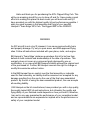
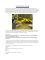
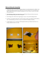
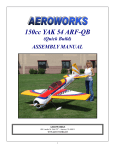
1 Hello and thank you for purchasing the 50% Clipped Wing Cub. This will be an amazing aircraft for you to show off and fly. I have made a great effort into making this plane the best model you will ever build and fly. I have provided you with the highest quality kit and performance possible. I wish you great success in the assembly and flying of your new Bill Hempel’s ‘Team Edge’ 50% Cub. The biggest ARF in the WORLD! WARNING An R/C aircraft is not a toy! If misused, it can cause serious bodily harm and property damage. Fly only in open areas, and AMA approved flying sites. Follow all instructions included with your plane, radio, and engine. Bill Hempel’s ‘Team Edge’ airplanes guarantees this kit to be free from defects in both material and workmanship at the date of purchase. This warranty does not cover any component parts damaged by use or modification. In no case shall Bill Hempel’s liability exceed the original cost of the purchased kit. Further, Bill Hempel reserves the right to change or modify this warrantee without notice. In that Bill Hempel has no control over the final assembly or materials used for final assembly, no liability shall be assumed nor accepted for any damage resulting from the use by the user of the final user-assembled product. By the act of using the user-assembled product, the user accepts all resulting liability. I, Bill Hempel as the kit manufacturer, have provided you with a top quality, thoroughly tested ARF kit and instructions, but ultimately the quality and flying ability of your finished model depends on how you build it; therefore, I can not in any way guarantee the performance of your completed model, and no representations are expressed or implied as to the performance or safety of your completed model. 2 INTRODUCTION The 50% ARF Clipped Wing Cub is a highly aerobatic model. It is capable of both precision and 3D type maneuvers. Early in 2008, this airplane flew in a Basic class IMAC event where the pilot placed 5th out of 15 contestants! This airplane builds easily, quickly, and precisely, due to its state-ofthe-art CAD design, LASER cut technology, and outstanding quality. I hope you enjoy building and flying your new 50% Clipped Wing Cub. You will draw a crowd everywhere you fly! Congratulations! Great care has been taken in both the design and manufacturing of the 50% Clipped Wing Cub to allow for the strongest and lightest construction possible. Only the highest quality materials from the covering to the paint, and wood have be used in the construction of this model. The 50% Clipped Wing Cub has been individually hand built, covered, painted by trained and experienced craftsman with over 20 years of manufacturing experience. Using CAD design, laser cut technology and jig built fixtures, tongue and groove tabs ensures the straightest and strongest accuracy in all stages of production and assembly. The 50% Cub has been designed around the use of any twin cylinder 150-210cc engine. The prototype Cub flew on a 3W-157 with great success and had almost 1:1 power. You will have to decide on the type of flying that you want to do when deciding on an engine. If you are looking to perform Torque Rolls then the larger 200cc+ motor will be needed. Another consideration is that this airplanes comes out tail heavy and a larger, heavier motor will help with the Center of Gravity. The only issue you may experience is that the motor box has been drilled for the 150-157 motors. Modifications will be needed to mount the larger motors. The aluminum stand-offs provided may not be the correct size needed with the larger motors either. IMPORTANT Please read through this manual carefully, before starting the assembly of your new 50% Clipped Wing Cub. Inventory all parts and hardware for any imperfections or damage. Please notify 3 INTENDED USE This airplane should not be regarded as a toy. This is an aerobatic airplane and is recommended for pilots with sufficient aerobatic and R/C flying skills. This airplane is not intended to be a trainer for beginning pilots. This airplane must be registered in the AMA’s Experimental Category for aircraft weighing over 55 pounds. Please visit ; www.modelaircraft.org/documents.aspx for further information. READ! WARRANTY READ! It is important to notify www.billhempel.com of any damage or problems with the model within 30 days of receipt to be covered under warranty. If you wish to return this aircraft for any reason a 15% restocking fee will be charges to the customer. The customer will assume full responsibility of shipping cost and damage that may occur during the return of the airplane. All prior shipping cost prior to the return will not be refunded. Parts will be exchanged or replaced once the original item is returned at the owners' expense. If you have any problems, please contact www.billhempel.com. Bill Hempel can not insure the skill of the modeler and can not influence the builder during the construction or the use of this aircraft, therefore, will not be accountable for any property, property damage, bodily injury or death caused by this aircraft. Bill Hempel / Team Edge cannot insure the skill of the modeler and can not influence the builder during the construction or use of this aircraft, and therefore; The Purchaser/operator accepts all responsibility of any and all structural or mechanical failures. 4 Re-shrinking the covering 1. Open your kit slowly and take care not to damage any parts of the kit. Remove all parts from their plastic protective covers for inspection. Before doing any assembly or installation it is very important to re-shrink or retighten the already applied covering. Due to the shipping process, heat and humidity changes from different climates, the covering may become lose and wrinkle in the sun. If you take the time to re-tighten the covering, you will be rewarded with a lasting beautifully covered model. 2. Using your covering iron with a soft sock, gently apply pressure and rub in the covering. If any bub- bles occur, your iron may be to hot. Reduce heat and work slowly. You should be able to just see the wood grain under the covering when proper adhesion has occurred. IMPORTANT Go over any and all seams and color overlaps with your iron to assure good adhesion of the covering to the wood. This is especially important at the Leading edges of the wings and stabs and all overlapping material. 3. After all seems have been ironed down you can then use your heat gun with extreme caution. Take care not to apply too much heat to one area for long periods of time. This may cause the trim colors to over shrink and pull away leaving unsightly gaps on the color lines. The trim stripes are especially vulnerable to over shrinking. 4. Your model is covered with Ultracote covering. In case of repairs, the colors are: Cub Yellow # Black # If you have the Hazel Sig’s scheme Cub, the colors are: Blue # White #870 Tightening and re-shrinking the covering is now complete. 5 ITEMS NEEDED TO COMPLETE Hardware: 150 –210 cc twin cylinder motor Mufflers for engine or header and canister for above engine Engine mounting bolts Propeller Cub spinner (recommended) Fuel tank and accessories (50 ounce tank recommended) Throttle Servo (standard size) Choke servo (optional) Aileron servos (minimum x 4 @ 300 ounce torque each) Rudder servo (minimum x 2 @ 300 ounce torque each) Elevator servo (recommend x 4 servos @ 300 ounce torque for each elevator half) Receiver battery (recommend minimum 2 batteries) Powerbox or power distribution board (recommended) Receiver/Ignition switches HD 22ga. Extensions for servos/batteries Receiver (6-channel minimum recommended. 2 receivers recommended with the use of a power distribution board) Dubro accessory package (optional) TOOLS: Allen wrenches both US and Metric Dremel cutting wheel and accessories Electric drill and bits Razor saw Hobby Heat Gun Hobby iron 6 TOOLS (cont): Modeling knife Needle nose pliers Paper towels Pens, pencils, ruler Screw drivers Scissors Adhesives: Canopy glue Blue Lock-tite Epoxy and mixing cups CA and accelerator Rubbing alcohol This completes the required items needed for the completion of this airplane. 7 Wing Assembly Servos 1. The ailerons have been pre-hinged and glued to the wing panels and are ready for flight. No other steps are necessary for hinging on the wings. 2. Place the wing upside down on a clean floor or table. Use caution to verify nothing scratches the top side covering or poke holes in the film while working on the wings. Use a blanket or large sleeping foam to protect the wing and covering while working. 3. You will need to decide if you are using 2 or 3 servos per aileron. If you are using 3 servos per aileron, locate and find the servo holes in the wing. Using care, cut the covering away from the servo holes. If using 2 servos per aileron locate the inner and outer servo hole and remove the covering. A electronic soldering iron works great for cutting precise hole through the covering. 4. Place your servos in the perspective locations and measure the length of servo leads you will need for extensions. When connecting servo extensions I use just a smear of canopy glue on connector to help keep connectors from separating. 5. Starting with the most outer servo hole, run extension through the wing and mount servo using standard methods. If using the Futaba 9152 servos, you will first have to enlarge all servo holes in the wing prior to installation. 6. Mount the middle servo and servo lead if running 3 servos per aileron. Install the most inner servo next if only using 2 servos per aileron. I recommend using 3 servos per aileron for the best positive control and least likely event of having blow-back from such a such large aileron. 7. Install all aileron servos and leads on both wing panels. 8 Control Arms 1. I recommend using Nelson Hobby or Hanger-9 10/32” control arms in all control surfaces on the 50% Cub. 2. Locate the 1/2” diameter harden wooden dowels in the ailerons. These will be located just behind each aileron servo on each aileron. Using a hot soldering iron burn a quick hole in the covering to gain access for inserting the 10/32” control arm. Do not go through to the top side of the aileron. 3. Using thin CA, put a drop in each hole to “harden” the wooden dowels. After the glue has dried, drill and tap the hole for a 10/32” thread. Do not go through to the top side. Measure the depth of the hole first. The threaded control arm only needs to screw into a depth of approximately 1” to 1 1/4” to have sufficient strength. 4. Using a drill, insert the 10/32” control arm into the drill. Measure the 10/32” threaded arm and mark it to 1” to 1/14” length. Insert the control arm into the hole and screw in place. Once the control arm is in place remove the drill and verify your work. If you are satisfied re-attach the drill and take the control arm back out. When ready, put a couple of drops of CA+ into the hole and one on the base of the control arm and re-screw the arm in place. 9 Control Arms(cont) 5. Remove the drill and proceed to perform the same tasks to the remaining control arms. Note: You will need to remove the screw head of the 10/32” control arm to use the method described for this installation. Let the control arms (glue) dry before proceeding. 6. After all control arms are glued in place, insert the black nylon base blocks to all control arms. Use caution when apply these base blocks and make sure you do not rip the covering as you tighten these down. There will be a small gap underneath these blocks as the control arms are not parallel to the aileron control surface, this is normal. Do not over tighten these blocks. 7. Locate the swivel links for the control arms. Using a drill and 10/32” tap, re-cut new 10/32” threads in all swivels using a 10/32” tap. This will allow the swivel links to move/pivot on the control arms while the servos move the control surface. This is very important to the smooth operation of the controls. 8. Once all control arm are installed the next step is to make the 4/40 pushrods to connect the servos to the ailerons. I use Du-bro’s 4/40 threaded turnbuckles. Insert all control arms to the proper length. This should complete the control arms and pushrod installation. Remember to go through and program all servos for proper geometry prior to connecting the servo arms to the control surface. 10 Stab and Elevator Assembly 1. The horizontal stabs uses conventional hinging and must be inserted and glued prior to flight. Locate the Robart-type hinges and trial fit into each hole of the elevator and stab. Use a hot soldering iron again to burn/clean each hole, this makes the gluing process easier as there is not any excess material to get in the way. 2. With all the hinges laid out on a paper towel, put a small drop of oil/grease on the pin to prevent glue from binding the hinge when inserted and glued. 3. Glue all hinges in the stab/elevator using hinge glue, epoxy or your preferred gluing method. 4. Locate the servo location in the stabs. Cut out for each servo using a razor blade or the hot soldering iron. I recommend using 2 elevator servos per elevator half for redundancy and safety. 5. Carefully thread your servo connector leads through the channels provided and install each servo starting with the most outer servo first. 11 Stab and Elevator Assembly (cont) 6. Install the 10/32” control arms in each elevator half using the same methods as used for the ailerons. It is important that each 10/32” control arm go through the elevator to nearly the top surface of the elevator. Going completely through the control surface is not necessary if you properly install these arms and get a good glue job on the control arms. Measure the thickness of each hole and make sure to install the control arms to 90-95% of the thickness of the elevator. Use enough glue to secure in place after threading. It is important to get a 100% bond here! 7. Install the black control blocks to the base of the 10/32” control arms, secure in place with a drop of CA prior to securing in place. These blocks should fit completely flat on the bottom of the control surface. Remember not to over tighten these as it could tear the covering. 8. Insert the swivel links and remember to re-tap the threads in the link to prior to installation for a smooth non-binding control surface movement. 9. Measure and cut the Du-bro’s 4/40 turnbuckles to connect the control surface to the servo arm. I Make sure to use aluminum servo arms! Do not use servo arms bigger than 1.5” as the servo resolution with be reduced and servo power to the control surface will get weaker. Do not use plastic or similar type servo arms as these will flex and possible loss of control could result. 10. Perform all your servo programming for servo center position and end points prior to servo arm installation to prevent binding and stripping of servo gears. 11. To mount stabilizer, insert both aluminum stab tubes and slide stabs in place. Locate and insert (2) bolts from the top side down on each side of the stab. Secure stab with flying wires. NEVER fly the airplane without the flying wires connected. 12 Flying Wires 1. Attach the flying wires to the vertical fin and horizontal stabilizer using material’s provided. 2. Bolt on to the bottom bracket to the bottom rear fuselage. 3. Attach all brackets to the tail Note: Flying wires/attachments may be different in your kit versus the pictures above. Rudder 1. Locate the hole for the rudder control arm , using a soldering iron clean out the holes for the control arm at the bottom and also the holes for the hinges. 2. Using the methods as described above, glue the hinges in and install the rudder to the fuselage. 3. Install the 10/32” control arm to the bottom of the rudder. Drill and tap the hole prior to inserting the control arm. Secure in place with nuts and washers. Use thin CA to coat the wood threads prior to installation of control arm. Once the glue is dry, re-tap the threads. 4. Re-tap the black nylon 10/32” swivels and insert on the 10/32” control arm. 5. When applicable, hook up rudder cables once all servos are installed in the plane. 13 Fuselage 1. The first thing to make sure you have done is to go over all the seems again with an iron. For added security, add ‘clear Monokote’ strip over each seem. Use a 3/4” clear Monokote strip and iron over the seems. This will eliminate the seem from pulling apart while heat shrinking the material with a gun. I know this is a lot of work but I have seen Ultracote pull apart when overlapped. Care must be used when shrinking the large surface areas of the fuselage. 2. Lay the fuselage upside down on the floor. 3. Locate and install the tail wheel. Landing Gear 1. To install the landing gear, it is recommended that the fuselage be placed upside down on the floor. Use a blanket or some type of soft material to protect the finish of the plane. 2. Locate the pre-drilled holes in the bottom fuselage for the landing gear and open them up. 3. Using the bolts provided for the landing gear, assemble landing gear and place on fuselage. Use the bungee provided to help keep gear from spreading apart. 4. Install the forward bolts into each side of the landing gear to trial fit the gear to the fuselage. 5. Temporarily install the wheels and axle to check landing gear’s alignment. Align the rear mounting holes with the fuselage and verify the wheel alignment appears to be straight with the fuselage. If needed, reposition the rear holes and re-install ‘T’ nuts inside the fuselage. (This procedure should not be required but it is a good check to do now). 6. Once you are happy with the wheels alignment, install the mounting bolts for the landing gear. Remember to use lock-tite to help prevent the bolts from coming loose. 7. Install enough bungee cord to support the airplane while finishing the model. Final adjustments can be made once the airplane is fully assembled . 14 Landing Gear (cont) Wheels 1. When installing the wheels, I have found that adding a thin washer on both sides of the wheels help reduce wear on the outer hubs. 2. Use axle grease or something similar when installing wheels to the axles. Slide the wheel assembly onto the axle. 3. Loosen the screw on the landing gear for the axle and install axle/wheel assembly. 4. Press the axle into the landing gear and tighten screw. Verify the wheel still turn easily without binding. Use lock-tite on the axle screw to prevent loss of wheel during flight. 5. Note: A brass insert may increase the life of the wheels. You may consider drilling out the axle hole in the yellow hub and inserting a brass sleeve to increase the strength of the wheel and longevity of wear. My prototype did not require this and new airplanes as of Sept 08 will have a new designed wheel with a beefier hub. (aluminum sleeve in picture was with older design wheels) Fuselage (cont) 4. Now that the landing gear is on the airplane, the fuselage can now be placed on its wheels. Make sure you have enough bungees to support the weight of the plane. 5. If you haven’t done so already then go ahead and glue the rudder onto the airplane. Locate and cut out the covering for the rudder cable exit guide in the rear part of the fuselage. Do NOT install rudder servos in the back of the fuselage, only in the cabin area. (CG issues) 6. Install your rudder servos inside the fuselage area. The airplane will need between 1.5 – 2.5 pounds of nose weight. Make sure when mounting equipment you plane ahead and mount everything as far forward as possible. Do not mount the receiver near ignition module or batteries. Care must be used to protect your receiver from RF noise. 15 Fuselage (cont) 7. Trial fit your cowling and become familiar with the process for assembly and removal of cowling. The use of cotter pins and washers will be needed to secure the cowling to the fuselage. 8. Mount your 150cc—210cc engine to the firewall. Use the lower half of the cowling to verify the engine is in the correct location. The firewall comes pre-marked for the standard 150cc engine but use this only as a guide and not an absolute. You should plan for up to 1” clearance between the propeller and the front of the cowling. The further forward your engine is mounted, the better the CG and also the better cooling you will have of your cylinders. 9. Once the engine is in the correct location verify the cowling will attach without interference. You should have ample clearance between the cylinder fins and cowling to prevent rubbing. Newer planes as of Sept 08 should have the new cowling which incorporates the ‘dummy engine’ as part of the cowling. The use baffles to help keep the engine cool is recommended. NOTE: New kits as of Sept 08 will have the new designed cowling with the dummy engine as part of the cowling and not as a separate item. This will make construction and assembly easier. 16 Fuselage (cont) 10. Mount the throttle servo on the motor box. Using a side mount single servo tray or something similar, install the servo to the motor box, secure tray. Install throttle linkage. (Picture is of ZDZ-210 rear induction motor which requires the throttle servo in the front of the firewall). 11. Install fuel tank in the rear portion of the motor box. Velcro tape works great for mounting the fuel tank. Use 3/4”-1” wide Velcro in the front and rear portion of the fuel tank to hole in place. You will need to cut the appropriate holes in the mounting floor for the Velcro to go through. Route all fuel lines and fuel dots at this time. If you choose to do so, a smoke tank may be added as well. A 50 ounce fuel tank will give you about 18 minutes of flying on a 150cc motor. 12. Install your ignition module, battery and switch. Remember to mount these items up front in the motor box area to help with the CG. There are 2-holes cut on each side of the fuselage for mounting your ignition and or receiver switch. The use of foam padding and velcro make for an easy way to secure ignition/ receiver batteries. Radio 1. With the rudder servos mounted inside the cabin area, the next step is to mount the rest of your radio gear. 2. The receiver batteries should be wrapped in foam and with velcro, mounted to the forward motor box area. 17 Radio (cont) 3. I highly recommend using a power board or power box distribution unit. I like using the SMARTFLY boards personally. These board are a great way to add safety to your plane’s redundancy . Install your receiver or power board behind the fuel tank area. You may have to make additional power leads to run from you receivers/power boards to your batteries or voltage regulators. 4. Install some type of separate ignition cut-off unit to meet the AMA’s safety guideline for the experimental category as published on the AMA’s website. Again, SMART-Fly has a very nice fiber-optic unit that plugs directly in-between your receiver and ignition module. 5. Connect/install the rudder cables from your servo’s to the rudder. 6. Install switches, servo extensions and the rest of the radio gear. Complete a full system check out with your airplane and all servos. Make sure you have set the correct directions on all surfaces and throttle. Assembly 1. Now it is time to finish up and prepare your plane for final assembly. Install both forward and rear wing tubes into the fuselage. 2. Install both wing panels to the airplane. Make sure you have a helper helping you! 3. Install the horizontal stab and connect all servo leads both for elevators and ailerons. 4. Run all the required servo extensions and permanently mount them in place where they need to go. 18 Assembly (cont) 5. With help, you will need to turn the airplane up-side-down again. The best way to do this is to place the airplane on its nose and flip the airplane over in this direction. 2-people should be able to accomplish this without too much trouble. You may need to take your airplane outside if you do not have sufficient room. Remember to always protect the airplanes covering from scratches, use a blanket or something soft to lay the airplane on once it is inverted. 6. With the airplane up-side-down on a flat surface, we may now proceed to install the wing struts to the airplane and make the proper adjustments to the attachment points. 7. Locate and assemble each side’s wing strut assembly. 8. Install the lower mounting tab to each side of the lower fuselage for the wing strut attachment. 9. Mount each side’s wing strut assembly to each wing half. Install the brass linkage adjustments to the strut and match up with the fuselage tab. Once final alignment is complete use lock-tite and secure connector to the strut. The pin /strut attachment should line up easily without having to bend or add pressure to align. NOTE: The reason we place the airplane inverted is to insure there is no load on the wings when making the final adjustments to the wing strut linkage. This will also insure that the wing is flat without dihedral or anhedral, this will also prevent the builder from ‘pulling” a warp into the wing trying to get the struts to attach. 19 Assembly (cont) 10. Once you have completed the adjustments necessary for the wing struts, you make turn your airplane over and sight down the wings, everything should be perfect using this method. Here are a few pictures to help you with the struts: 20 Assembly (cont) 11. Remove wings with the help of your helper. You may leave the wing struts attached to the wings, just disconnect the attachment at the fuselage. Place wings in a safe area, they should be ready for flight now. Windows and windshield 1. Now it is time to install the windows and forward windshield. If you have waited this long to do this then I am proud of you for following the instructions! 2. Starting with the rearward most window, install window’s using RC-56 or equivalent canopy glue. Use blue (painter’s ) tape to hold the window in place until dry. 3. Work your way forward with the installation of all side windows. NOTE: You may modify a side window to be removable to aid in getting to your equipment. 4. The forward windshield needs a lot of attention to make sure it is installed properly. Place the plastic windshield in place and trial fit this piece. The areas to watch out for are the top and bottom flanges. It is possible to ‘force’ the shape of the plastic and have it not fit properly, this can cause cracks later in life. NOTE: I recommend using canopy glue only when installing the windshield. Screw’s work well but you have a higher chance of creating a stress crack on the windshield due to engine vibration and prop blast. 5. While the windshield is in place, use a soft felt tip pin to trace around the area to know where to glue to. 6. Prior to gluing, use a “T”- pin and punch small holes through the covering to get the glue to penetrate into the wood area for a good bond. You should have holes everywhere inside the perimeter of the canopy painted frame area. 5. When you are satisfied with the fit, glue the windshield in place. Use sufficient glue to get a good bond. The areas often missed is the airfoil section of the windshield where the wing butt’s up to the plastic. 7. Use painter’s tape to help hold windshield in place for at least 24 hours. 8. Use clear tape or yellow tape and tape down the perimeter of the canop’s edge along the base and sides of windshield. This will help reduce airflow from lifting the windshield away from the fuselage. 21 Engine Exhaust 1. If you are using mufflers for your engine you will need to cut muffler exit holes in the lower half of the cowling. This should be straight forward and require little more explanation. 2. For canister installations there should be plenty of room. Mount your canisters in the area provided using the manufactures recommendation for the type of canister you are using. 3. For additional air flow through the canister area, open up the exit holes in the bottom of the fuselage between the landing gear legs. Only 2 hole need to be opened but all four holes can be opened also if you choose. 4. For canister operation only, it is recommended to open the last hole in the bottom rear portion of the fuselage. This will allow airflow to pass through the fuselage and keep temperatures to a minimum. ZDZ-210 3W-150 Air exit for canister use 22 Control Surfaces 1. After all your servo’s are programmed for zero binding at center, it is time to set up the throws for the proper deflection. This is going to be pretty easy as we will want to get as much throw as possible on everything! 2. Ailerons: I recommend a minimum of 1.5” servo arms with 2” arms being ideal. Use aluminum servo arms on ALL control surfaces. Aileron differential will be needed to reduce the amount of adverse yaw while rolling. Set your controls so that you have a minimum of 30 degrees throw for the up and around 25 degrees for the down. Aileron differential can be adjusted after the test flight to minimize the adverse yaw. Set the maximum amount of deflection as you can get. Activate your dual rates and set the throw to 50% for low rates. 3. Elevator: Using a 1.5” or 2” aluminum arms on your servos, set the maximum up and down elevator so that you have at least 30 degrees throw. Again have dual rates set up using 50% for low rate. I set my planes throws so I could get as much up/down as possible without sacrificing servo resolution too much. 4. Rudder: As much as possible. I did not need dual rates for rudder. I had the rudder hitting each elevator for my rates. You will find you will need as much as possible. Balancing 1. This is going to be hard to do. Lifting this plane to check the balance is way hard. I checked my CG without the wings mounted. The 50% Cub does have a large CG range and can be flown with a rearward CG with good hands. Your CG should be between 8” to 10” back from the leading edge. I believe the airplane fly’s best with a more forward CG. Test flights have been made with the CG as rearward as 12” but is not recommended. Test Flight 1. The test flight should be made in the presence of an official AMA ‘inspector’; and after you have been given the “permit to fly” paperwork. By following the rules as outlined by the AMA for the Experimental Category, you will have an extra set of qualified eye’s looking over your airplane and checking your work. This will also give you insurance coverage in the event of an accident. Be smart, follow the rules. More information can be found here: http://www.modelaircraft.org/PDF-files/520-A.pdf 2. The test flight should be made with full fuel (better cg) and on a good weather day. You can set low rates for everything but the rudder, leave the rudder at full rate. Takeoff with a 150 cc engine is pretty fast. I recommend not to do a partial power takeoff, just apply power and go to full throttle. Climb out should be pretty spectacular, climb and reach a safe altitude in the event of an engine failure before turning. Once you have achieved a safe altitude, throttle back to about 30-40% power and adjust trims if needed. Perform you flight always within glide distance of the runway. At this reduced power setting you should have a ton of time to 23 Test Flight (cont) get use to the airplane. The biggest secret to flying this 50% airplane is to take you time and get use to flying it! I have had experienced pilots crash their beautiful Cub because they became over confidant with their abilities flying something they were not use to. Take you time and become familiar. After a few minutes of flying the airplane you should become pretty confidant and it is time to go to an idle and perform a few power off glides (idle only). Become familiar with the glide rate and glide distance of this new plane. When ready, perform your landing and check everything over. Perform a good post flight inspection. Look closely at the wing struts, control surfaces, servo, radio gear, engine etc. Aerobatics 1. Performing aerobatics is the most fun you can have with this airplane, that and touch and goes. Loops and rolls are done easily, remember to perform these at altitude to learn the characteristics of this plane before attempting these low to the ground. Move your CG around if you think it will perform better. The 50% Clipped Wing Cub has already been flow in IMAC competitions and has finished 5th place out of 15 pilots in the basic category. This was the pilots FIRST IMAC event too! 2. Inverted flight: This airplane has a flat bottom wing so caution needs to be exercised while flying inverted! At times if you develop a high rate of decent while inverted you may experience trouble maintaining altitude or stopping the decent prior to impacting the ground if you are too low. Use caution! 3. Spins: This airplane performs the best spins ever! Take the plane high and go to an idle. Apply up elevator slowly until the airplane stalls, then apply full rudder and elevator and watch the spins all the way down. Recovery is as quick as releasing the inputs to neutral 4. Snap Rolls: Performing both positive and negative snap rolls are not an issue with this plane. Don’t expect a high rate of rotation but it will be faster than rolling. Snap rolls are fun, especially at the top of loops. 5. Torque Rolls: For those of you with the 170 –210 cc engines, torque rolls should be possible. Have fun Have fun performing any and all aerobatic maneuvers you can think of. This airplane is strong and will not have any issues performing for you. Remember though: This is a 50% scale airplane and it is breakable if abused. Do not perform full throttle dives and pull full-up to see if you can break the airplane. I am sure if you tried, you could figure out a way to break it. Use common sense and have fun! Questions: If you are confused on something or need help, send me an email. I will do my best to give you the best customer service as possible. I am here to help you enjoy the LARGEST ARF in the WORLD! Bill Hempel 24 Pictures 25