1
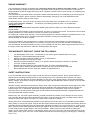
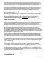
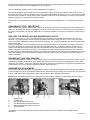
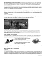
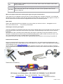
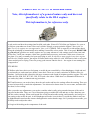
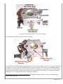
DLA 32-56-112
OPERATING INS TRUCTIONS
Petrol Air Cooled Engines for large Radio
Controlled Aircraft, with Electronic
Ignition.
CONTENTS
32cc SPECIFICATIONS:...................................................................... Error! Bookmark not defined.
32cc SPECIFICATIONS: .................................................................................................................... 2
56cc SPECIFICATIONS:..................................................................................................................... 2
112cc Twin Cylinder SPECIFICATIONS: ............................................................................................ 3
Do this first: ......................................................................................................................................... 3
DISCLAIMER: ..................................................................................................................................... 3
ENGINE WARRANTY ......................................................................................................................... 4
THE WARRANTY DOES NOT COVER THE FOLLOWING: ............................................................... 4
SAFETY INSTRUCTIONS .................................................................................................................. 4
ENGINE INSTALLATION .................................................................................................................... 5
CDI IGNITION SYSTEM ..................................................................................................................... 5
ENGINE BREAK IN and LUBRICANTS .............................................................................................. 6
CRANKSHAFT STUD: IMPORTANT! ................................................................................................ 7
DRILLING THE PROPELLER AND SPINNER BACK PLATE. ............................................................ 7
SPINNER NUT AND PROP WASHER................................................................................................ 7
CARBURETOR ADJUSTMENT .......................................................................................................... 7
STARTING THE ENGINE ................................................................................................................... 8
ENGINE MAINTENANCE ................................................................................................................... 8
ASSISTANCE ..................................................................................................................................... 8
EASY CHOKE SETUP ........................................................................................................................ 9
COWL VENT / COOLING OPENINGS................................................................................................ 9
FUEL FILTERS and FUELERS ........................................................................................................... 9
32cc SPECIFICATIONS:
Performance...
Output Power:
Idle Speed:
Maximum Speed:
Static Thrust:
Bore and Stroke:
Displacement:
Compression Ratio:
Weight:
3.8HP at 8200rpm
1700 rpm
9000rpm
8.8 Kg at 100 meters altitude
37mm×30mm
32.23 cc
7.6:1
Engine - 920g
Ignition - 120g
Exhaust - 65g
Requirements
Fuel:
2C Regular Gas mixed 30:1 - 45:1
Synthetic (Cool Power Blue preferred) or High quality Petroleum
Propeller:
18×8; 18×10; 19×8; 20x8
Ignition Battery:
4.8 to 6.0 Volts >=1200Mah
Replacement Spark plug: NGK CM6 or equivalent Gap: 0.018" to 0.020"
Installation torque:
7 to 8 ft-lbs.
Configuration
2Cycle air cooled
Pump carburettor with manual choke
Automatic advancing electronic CDI ignition
56cc SPECIFICATIONS:
Performance...
Output Power:
5.6HP at 7500rpm
Idle Speed:
Maximum Speed:
Static Thrust:
Bore and Stroke:
Displacement:
Compression Ratio:
Weight:
1300 rpm
9000rpm
13.8 Kg at 100 meters altitude
45mm×35mm
56cc
7.8:1
Engine - 1300g
Ignition - 104g
Exhaust - 112g
Fuel and Ignition Requirements:
Fuel:
2C Regular Gas mixed 30:1 - 45:1
Synthetic (Cool Power Blue preferred) or High quality Petroleum
Propeller:
22×8; 22×10; 23×8
Ignition Battery:
4.8 to 6.0 Volts >=1200Mah ( after July 2010 7.4V)
Replacement Spark plug: NGK CM6 or equivalent Gap: 0.018" to 0.020"
Installation torque:
7 to 8 ft-lbs.
Configuration
2Cycle air cooled
Pump carburettor with manual choke
Automatic advancing electronic CDI ignition
PAGE 2 OF 22
112cc Twin Cylinder SPECIFICATIONS:
Performance...
Output Power:
Idle Speed:
Static Thrust:
Displacement:
Bore and Stroke:
Compression Ratio:
Weight:
Cap to cap width:
Mount to prop hub length:
Centreline to carb:
11.5HP at 7500rpm
1400 rpm
24 Kg at 100 meters altitude 210Kg at 1800 meters
112 cc
45.1mm×35mm X 2
7.8:1
2510 grams + Ignition 12g + Mufflers 117g
29cm / 11.4in.
167mm / 6.6in.
13cm / 5.1in.
Fuel and Ignition Requirements:
Fuel:
Propeller:
Ignition Battery:
Replacement Spark plug:
Installation torque:
2C Regular Gas mixed 30:1 - 45:1 (petroleum based for break in synthetic thereafter)
27x10 benchmark; 26×10; 27x12; 28x10
4.8 to 6.0 Volts >=2000Mah
NGK CM6 or equivalent Gap: 0.018" to 0.020"
7 to 8 ft-lbs.
Configuration
2Cycle air cooled
Pump carburettor with manual choke
Automatic advancing electronic ignition
Intended Usage:
These engines are designed for use in radio controlled model airplanes. With its high power output and light weight,
they are ideal aircraft use. Read and follow all of the Operating Instructions before you start your motor.
Congratulations and thank you for purchasing one of the highest quality, high-performance model aircraft engines
available. Your DLA engine has been specifically designed, developed and manufactured from proprietary
components for model use. It is very powerful, extremely lightweight, easy to handle and adjust, and should
provide years of outstanding performance.
It is extremely important to read and understand all of the instructions contained in this manual before starting your
engine, especially the Safety Instructions.
The importance of following the safety instructions at all times cannot be
over-emphasized!
DLA engines start very easily and develops enough horsepower to cause serious injury or death to the operator
and bystanders. We here at TATES PERFORMACE HOBBIES are concerned for your safety and the safety of
others so PLEASE follow the safety instructions at all times!
Do this first:
Inspect the engine before signing for it and have the delivery agent note any damage to the carton and/or motor.
Also report any shipping damage to us immediately.
DISCLAIMER:
DLA engines are intended for model use only and should never be used in any form of manned craft or vehicle. DL
reserves the right to change prices, models, designs, components, specifications, and accessories of all products,
at any time, without prior notice or obligation. DLA shall not be responsible or otherwise liable in any way for any
form of loss, injury, or damage that may result from the use this motor.
WARNING!!!
DLA engines are not toy motors. Serious injury and even death may result from improper use. You alone
are responsible for its safe and proper operation. TATES PERFORMANCE HOBBIES is not responsible for
any injury, damage or other loss resulting from its use. If you do not agree, you must not use the engine.
PAGE 3 OF 22
ENGINE WARRANTY
The manufacturer's warranty guarantees that "the engine will be free of defects at the time of sale". In addition
to the manufacturer's quality control procedures, we inspect all DLA engines prior to shipment to customers so
material defects should be caught before they get to customers. We don't test run them though, so something may
get passed us.
The manufacturer’s guarantee does not extend to failure of the ball bearings or to breakage of the connecting rod.
Crash damage, neglect, abuse, improper customer disassembly, tampering, use of sub standard fuel will
automatically void the warranty of the engine.
For warranty service, send your engine and proof of purchase date (copy of original invoice or receipt) to –
TATES PERFORMANCE HOBBIES. 135 Shannon Ave Geelong West VIC 3218 Ph 03 52224201
[email protected]
Please enclose a complete written explanation detailing the problems. State your name, address and phone
number clearly.
You may request an estimate of services at the time you return your engine for service. An omission of this request
implies permission for Tates Hobbies to service your engine at our discretion.
For repairs not covered under warranty, you must specify whether you wish the charges to be billed COD or to your
Visa or MasterCard (be sure to complete credit card information including the expiration date).
Please package your engines carefully.
As it is not possible for the manufacturer to control the circumstances of the operation of model engines, the
manufacturer can not be responsible for any accident occurring in the course of the operation of model engines.
The manufacturer assumes no liability for injury or loss resulting from the use of these engines beyond the cost of
the engine if there was a defect in material or workmanship of the engine.
THE WARRANTY DOES NOT COVER THE FOLLOWING:
•
•
•
•
•
•
•
•
•
Any disassembly of the motor. The warranty is void if the engine is disassembled in any way!
Stripped or cross-threaded spark plug threads.
Damage caused by improper handling, tuning, or maintenance.
Damage resulting from any type of crash.
Damage caused by alterations, which, in our opinion, affects the engine’s condition or operation.
Tune-ups, including spark plugs.
Damage that may result from using fuels other than 87 octane unleaded gasoline.
Ignition system damage caused by failure to follow the wiring instructions and warnings.
Normal adjustments such as carburetor needles as explained here in.
SAFETY INSTRUCTIONS
If you are unfamiliar with this type of engine, seek the help of an experienced user. Never operate it alone or
without proper knowledge and experience on hand. Always have your club Safety Officer inspect your engine
installation, plane and radio set up before attempting to use them. Verify proper ignition, receiver and transmitter
battery voltages, and perform a range check before every flight. NEVER attempt to start the engine or fly with radio
"glitches" of any kind.
Gasoline is highly flammable and hazardous; always have a fully charged fire extinguisher at the ready when using
it; always use it with extreme caution and with approved containers and fueling equipment. Never operate your
engine indoors or in a closed area. Remember to keep engine fuel in a safe place, away from any sparks,
excessive heat, or anything which could ignite the fuel. Remember that gasoline/mixture is highly flammable and
must be handled with extreme caution.
Before every use, check the engine assembly, propeller and airframe carefully for any damage or loose screws,
nuts, and bolts. Normal gas engine vibration has a tendency to loosen things up when you least expect it. Never
attempt to operate the engine or aircraft if you suspect there might be a problem.
Always stand clear of and behind the propeller; never allow anyone to be in front of or to the sides of the propeller
when starting or running the engine. Anyone near the engine should wear protective eyewear and clothing. Keep all
spectators at least 30 feet away from the engine while operating the engine. Do not put anything (i.e., fingers, body
parts, objects into the rotating propeller Wear proper apparel. Do not wear loose clothing, gloves, neckties, jewelry,
or neck straps which may get caught in the moving propeller. Always wear eye protection when starting the
engine. Do not smoke while running or operating the engine. Do not run the motor near loose material such as dirt,
gravel, power cords, ropes, sand, etc. Loose material can be drawn into the turning prop causing injury or damage.
PAGE 4 OF 22
Always use a correctly mounted (correct length bolts, no spacers behind it, not touching the spinner cone, etc.),
and properly sized propeller. Never use a propeller that has been damaged, modified or repaired or that has not
been properly balanced. Always use the correct length propeller bolts and make sure they are tight before every
flight(screw thread-locking glue is recommended)
Always use a heavy duty starter stick or heavy leather work glove to flip the prop. Always have the airframe in a
starting stand and have someone else hold the plane when starting or running the engine. Never operate the
engine where anything (dirt, gravel, clothing, and any loose items) might be drawn into the propeller. Keep
spectators at least 50ft. away from your aircraft when operating the engine.
Unless you are starting it, never turn the engine over without first making sure the ignition is off. Always use an
ignition kill switch and have the throttle setup such that it can be used to stop the engine when necessary. Refer to
Page 5 – SmartFly Ignition Cutoff.
Never mount the engine in anything other than an airframe for which it's designed for use in. Overpowering an
airframe is dangerous and unsafe. Do not use an engine stand to run the engine. A stand may not allow engine
vibration energy to be properly dissipated and may cause failure of the engine mounting parts, propeller, propeller
mounting bolts or stand.
Always fly in accordance with the safety rules, regulations and recommendations of the MAAA. Read and
understand all of the safety material on their website www.maaa.asn.au/ Before using this engine.
ENGINE INSTALLATION
If using the mounting stand-offs, the cut ends should be mounted to the engine. If additional mounting height is
needed, it should be placed between the mounting hardware (brackets / stand-offs) and the firewall. Make sure that
all spacers are flat and of the same size and surface plane so as not to induce any twisting force into the mounting
hardware or damage to the engine or mounting hardware failure may result. Spacing should never be used
between the mounting hardware and the engine. In all cases, the firewall / airframe mounting surface must be
absolutely flat or potentially damaging forces can be exerted to the engine or mounting hardware which can cause
failure.
Check to see that the carburetor has adequate clearance (at least 1in.) to anything for proper breathing. If it
doesn't, make appropriate adjustments. Make sure that your airplanes fuel tank and lines are made for gasoline
use, that the tank is adequately vented and that the feed line clunk can move freely in all directions and not get
hung up anywhere. We recommend using a filter between your gas supply and airplane fuel tank. If you use a fuel
filter between the airplane tank and the carburetor, make sure it is of adequate size to supply an unobstructed flow
of fuel to the carburetor or the engine may not run correctly.
Make sure that the cowl openings on your plane provide enough airflow for proper cooling. Ideally, all of the cooling
fins of the cylinder should be exposed directly to unobstructed flow of cooling air and there should be 3 times as
much air exit area as intake area. Many planes have cowl openings that actually inhibit proper cooling of single
cylinder engines. Their openings were made to give a scale appearance of the full size planes they are patterned
after. Along with the openings described above, blocking the scale openings either partially or wholly can
significantly help promote cooling air flow over the cylinder fins.
The ignition battery should be mounted externally, near the cowl, at least twelve inches from the receiver or throttle
servo that connects to the receiver. The carburetor needs at least 1 1/2" (38mm) of clearance between the intake
and the bottom of the cowl.
If there is less than 1 1/2", make an opening in the cowl below the carb at least as large as the carb intake
diameter. A long, narrow, screw driver is recommend to drill small holes in the cowl for adjusting the needle valves,
since the carburetor must often be adjusted differently with the cowl on as compared to off.
These engines burn between one and two ounces of fuel per minute. Therefore, a 32 ounce or larger tank is
recommended. The engines are equipped with a diaphragm pump carburetor making tank location not critical
relative to the carburetors fuel entry position. Place the tank on the aircraft’s center of gravity (CG). Then aircraft
trim changes during flight will not be necessary from a full to an empty tank.
Many types of fueling devices (fuel dots, filler valves, etc.) are available for your use. Our experience has shown
that often the simplest is the best. Regardless of which device you decide to use, be very wary of air leaks as they
can be detrimental to the proper operation of your engine.
NOTE: Always use Loctite on engine mounting hardware and make sure your models firewall and engine box are
adequately reinforced (pinned, soaked in thin CA, etc.).
CDI IGNITION SYSTEM
PAGE 5 OF 22
The DLA ignition system is designed for input voltage ranging from 4.8 to 6.0 volts, no more and no less.
A battery pack of 1200mah or greater may be sufficient for a day of flying for most users. Check your battery
voltage with a voltage meter before every flight and do not fly if the voltage is not between 5.2 and 6.0 volts; the
voltage at the start of a flight may not remain for the duration of the flight. Disconnect the battery from the ignition
system while charging the battery. The ignition module should be connected to the battery through a heavy duty
switch, mounted where it can be reached easily when starting the engine.
NOTE: A 6 volt or larger battery pack must be regulated to between 5.2 and 6.0 volts or it will supply too high a
voltage to the ignition module. We recommend using a Smart Fly Ignition regulator.
The ignition module and its battery should both be "soft" mounted with 1/2in foam on all sides to avoid damage
from vibration. All parts in the ignition system should be mounted no less than 12in. away from any part of the
airplanes radio equipment to avoid possible interference. The shielded plug wire is wrapped in a plastic spiral
covering to help protect it from damage and wear. Even so it must be inspected frequently as damage to the
shielding may cause radio interference.
It is important to understand how the ignition system is to be wired. Mount the ignition module using the four
supplied rubber grommets so as to create a 1/16" gap between the ignition module and the mounting surface.
Without this 1/16" gap the ignition module can overheat.
Important: If the electronic ignition overheats it will malfunction (e.g., backfiring or shutting down).
Ignition details:
The red cable is positive (+),while the black is negative(-).
It is important to achieve the correct coordination of the sensor(s) to the magnets for fitting a new ignition.
The spark plug that comes with DLA engines is an NGK CM-6 or equivalent, gapped at 0.018in. to 0.020in. Torque
should be 7 to 8 ft-lbs. Be very careful not to over tighten it or damage to the cylinder threads may result. The plug
cap comes with an internal grounding spring and a split retainer ring around its base; they both must be used at all
times. The plug cap fits very tightly to the spark plug; you should feel a release of pressure when the cap seats
properly to the plug. It will also be difficult to remove the plug cap from the plug; be sure you pull straight out on the
cap and not on the plug wire. If the plug is not properly connected to the cap, damage to the module may result.
We highly recommend using the “SmartFly” Optical cable engine cut-out switch in any CDI ignition
installation. This unit optically disconnects your radio receiver from the high voltage CDI ignition – thereby
eliminating most of the electrical interference associated with gas engine ignitions.
The “SmartFly” Ignition Cutoff provides safety and convenience for your gas powered plane. The unit has two
modules that are connected by a fiber-optic cable. There is no electrical connection between your ignition and your
radio system. The unit recognizes dual-receiver setups and allows your engine to keep running if you lose power to
the receiver the Cutoff is controlled by but your second receiver still has power. You are not forced to land deadstick as with other units on the market. The LED on the ignition side is removable and extendable with standard
extensions. The LED is not required for the unit to operate properly.
The SmartFly Ignition cutout and Ignition Reg. is available from your
local hobby shop or see- www.rcworld.com.au
ENGINE BREAK IN and LUBRICANTS
Break in running should be done with regular or premium gas mixed
with a high quality synthetic based two cycle oil at a ratio of 30:1. The
recommended oil is COOL POWER Synthetic Blue. A good quality
petroleum based oil may be used, but we have found the synthetic is
still the best, even for break in purposes.
PAGE 6 OF 22
We have also found that Avgas works extremely well with these gasoline engines, mixed with Cool Power Blue you
will get the best performance and reliability from your engines.
See recommended propeller sizes in engine specifications on page 2.
For the first few flights you can keep the cowl off if possible to aid in cooling. The engine should never be run in a
test stand as they do not allow vibration energy to be properly dissipated. The engine run in should be flown at light
load and varying speed for enough time to have 3 gallons of gas run through the engine. The prop you use should
allow the engine to run at between 6700 and 7200rpm.
Once break in is completed the recommended synthetic oil is COOL POWER BLUE - 2 cycle mixed at a ratio of
45:1 .
CRANKSHAFT STUD: IMPORTANT!
When installing the propeller make sure the stud is screwed-in far enough to extend past the 7/16” shoulder of the
prop hub. The crankcase stud must engage the thick part of the hub in order to provide the necessary strength. If
the stud is not screwed-in far enough failure can occur possibly resulting in the loss if the airframe, serious injury or
death.
DRILLING THE PROPELLER AND SPINNER BACK PLATE.
The crank shaft is 8mm x 1.25 in size while the aluminum shoulder that protrudes from the prop hub is 7/16” in
diameter. You must therefore drill the spinner back plate and the rear of the prop hub to 7/16”. The rear of the
prop hub must be drilled deep enough to accept the remaining 7/16” aluminum shoulder that protrudes through the
spinner back plate.
Some prop hubs have two holes tapped into the front to keep the spinner and propeller from rotating on the hub.
Insert two hardened cap head screws into the holes and tighten securely. Then drill 2 holes in the back of the
spinner back plate that are the same size as the screw heads so the screw heads will fit into the holes when the
spinner back plate is inserted on the shaft. This will keep the spinner back plate from rotating on the shaft and if
the back plate is knurled it will keep the prop from rotating on the shaft as well. Hint: put some lipstick on the screw
heads and carefully put the back plate on the shaft and press it against the screw heads to mark the location of
holes to be drilled.
SPINNER NUT AND PROP WASHER.
The crankshaft threads are 10mm x 1.25 so use an 10mm X 1.25 spinner adapter nut to mount the spinner. Use a
steel washer between the aluminum prop washer and the nut to prevent the nut from digging into the front of the
aluminum prop washer. If the nut is allowed to dig into the aluminum prop washer it may give the impression that it
is tight when in fact it is not applying sufficient pressure against the prop.
CARBURETOR ADJUSTMENT
Every engine has been adjusted to average mixture settings which will most likely allow the engine to start and run
in most locations. However, as altitudes and barometric pressures vary by location and even by day, it is very likely
that the carburetor mixture settings will need to be adjusted to obtain optimum performance.
NOTE: Never make adjustments to the carburetor while it is running. Always use a tachometer to aid in making
adjustments to your carburetor. Some carburetor models do vary from that shown.
1
2
3
4
5
6
Choke Lever
Throttle Lever
Idle Speed Adjustment Screw
Low Speed Mixture Adjustment Screw
High Speed Mixture Adjustment Screw
Ignition Sensor
The throttle servo should control idle speed as well as be able to cut the throttle to stop the engine when
necessary.
PAGE 7 OF 22
The average mixture settings are 1&1/2 turns out for the low speed circuit (See No. 4), and 1&3/4 turns out for the
high speed circuit (See No. 5). Carburetor mixture adjustment starts with the low speed circuit. The low speed
should be set such that the transition from idle to full throttle is smooth, even if the throttle is snapped to full. This
will likely result in a slightly rich idle mixture but you're better off with that than a rough transition. If the engine dies
when the throttle is advanced, the mixture is likely too lean. If the engine stumbles when the throttle is advanced,
the mixture is likely too rich. Since the low speed mixture has some effect on high speed mixture, always adjust the
high speed after adjusting the low.
The high speed circuit is properly adjusted when the engine can reach maximum rpm while in the air, which is
usually slightly richer than when it is on the ground. A general rule of thumb is to richen from the maximum on the
ground rpm by about 200rpm. If ever the engine slows or dies while at full throttle, the high speed mixture is likely
too lean and you should adjust it as soon as possible or damage can result.
NOTE: Be careful not to run the mixture screws in too far as damage to the screw and / or carburetor body may
result. Also, don't be tempted to run an overly rich mixture. Gas engine lubrication comes from the oil concentration
in the gas, not from a rich fuel / air mixture. If you want more lubrication, you can vary the oil mix ratio. A too rich
mixture will only result in poor engine performance and a fouled plug and combustion chamber.
STARTING THE ENGINE
COLD Step 1: Close the choke, advance the throttle to very slightly above the idle position, turn on the ignition and
briskly flip the prop through compression until the engine fires and then dies. If the gas line is dry, this may take 20
or more flips.
Step 2: Open the choke and briskly flip the prop through compression. The engine should start in just a few flips. If
it acts like it wants to start but doesn't, you may need to advance the throttle slightly.
WARM Open the choke, advance the throttle to very slightly above the idle position, turn on the ignition and briskly
flip the prop through compression. The engine should start in just a few flips. If it acts like it wants to start but
doesn't, you may need to advance the throttle slightly.
NOTE: It is possible to flood the engine by over choking. In this case, the spark plug must be removed and dried of
excess fuel. Make sure to have the ignition off when removing the spark plug.
ENGINE MAINTENANCE
Fuel tubing throughout the fuel system should be changed periodically and should never allow any air to enter the
system. If your gas line starts to get hard, soft or changes color, there's a good chance it needs to be replaced.
Keep in mind that the tubing inside your tank deteriorates more quickly than anywhere else in the system.
The exterior of the engine should be kept clean and inspected regularly. Tucked away inside the cowl, it would be
easy to miss loose nuts and bolts without frequent inspections. Dirt inside the cowl area can easily find its way into
the carburetor. It should be kept clean and free of dirt build up.
The carburetor fuel screen should be cleaned periodically also. Carefully remove the pump cover (inlet side of the
carburetor), gasket and pump membrane. The screen will be visible and can be cleaned after careful removal. If
ever the carburetor seems to need frequent mixture adjustment or acts like it's starving for fuel, a dirty screen is a
likely candidate for a cause. The carburetor should be inspected, cleaned or reconditioned with every flying season
or after being stored for a long period of time.
The spark plug should be inspected, cleaned and gapped periodically and replaced if it is fouled or worn. A new
plug with every new season is a worthwhile maintenance step.
ASSISTANCE
Additional information and the latest version of this manual are available at TATES PERFORMANCE HOBBIES
and answers to specific questions can be obtained by email at [email protected] or by phone at 03 522 4201.
#4 - Running the Engine on a Test Stand
The engine mounts supplied with the DL engines are designed to be used on an airframe intended for use with a
50cc/100cc gas engine. Running your engine on a test stand may very well cause them to fail. A typical test stand
does not allow the vibration energy produced by the engine to dissipate as it would if mounted in an airframe. As a
result, this energy causes undue stress to be exerted on the mounts and they will likely fail if run long enough.
When properly used, the engine mounts will provide trouble free operation. Our own experience has one set of
original mounts still performing flawlessly after over 176hrs of vigorous use.
Improper use of the engine or its parts may result in injury and property damage. Please read and follow all items
presented in the operating instructions. This is important for your safety as well as your enjoyment of the engine.
PAGE 8 OF 22
#3 - Testing Your Ignition Ground / Shielding
“Grounding” for the DL engines / ignition system is conducted through the Spark Plug / Spark Plug Cap (with Split
Ring Retainer installed) / Plug Cap Grounding Spring / Plug Wire Shielding / Ignition Module Case. If any part of
this circuit has been interrupted (worn, broken, torn, missing, etc.), an incomplete circuit can exist which might
cause radio interference.
The circuit can be tested with a Continuity Tester or Volt Ohm Meter, by attaching a test lead to the metal housing
of the ignition module (away from the clear label tape) and the other test lead to the engine. The tester must show a
completed circuit for it to be considered OK. If this circuit is incomplete, it should be repaired or replaced; a bypass
grounding circuit will not provide the required shielding.
NOTE: this test is not intended to be used in place of a complete (engine off and running) range check of your radio
system. A range check should be performed at the beginning of every flying day, or before any flight if you suspect
there may be a problem. Also, a careful visual inspection of the plug wire shielding should be performed at the
beginning of every flying day as a worn or frayed shield can allow interference to occur even if the grounding circuit
is complete.
EASY CHOKE SETUP
Here's an easy, inexpensive and lightweight way to set up a manual choke lever for your DL engine.
Attach a leftover servo arm to the engine mount bolt and run a servo control rod through it to the choke arm. Attach
the control rod to the arm with a ball link or nylon link so as not to create radio interference.
COWL VENT / COOLING OPENINGS
As a general rule, you need to have 3 times as much air outlet area as you have inlet area, for proper engine
cooling. We recommend that you open the front of your cowl enough to expose all the cylinder cooling fins to
incoming air. Cooling might also be improved by blocking some of the stock cowl vent area or by constructing
baffles to direct incoming air to the cooling fins.
FUEL FILTERS and FUELERS
While inline fuel filters are beneficial to long engine life, they can also be detrimental if too restrictive. Some fuel
filters are too restrictive for proper fuel flow even when they are new. If you use a filter between the tank and
carburetor, make sure it has a large enough capacity for proper fuel flow.
The TY1 (2025) Fuel Filter is suitable for this job,
having a “sintered bronze” element
that is not affected by petrol and is easily cleaned.
The TY1 (1161) Hand Fuel pump is also suitable
for Petrol as well as Glow Fuels, with no electric
motor it is safe to use with petrol.
Fuelers that have spring operated seals can malfunction enough to cause an air leak that will affect proper running
of your engine. Fuelers that have no moving parts such as fuel dots are less prone to air leaks and thus more
reliable.
What's the torque spec on the spark plug?
7 to 8 ft-lbs.
Running in procedure
The main thing to avoid with any new engine is excessive heat. It can cause damage very quickly to any engine. To
avoid this it is important to keep the mixture RICH. The extra fuel keeps the engine running cooler. Start by running
the engine in the model on the ground for 2 or 3 tanks of fuel. This ensures that the engine will run consistently and
reliably and avoids any dead stick landings while the mixture is set rich. When happy that the engine will not stop,
PAGE 9 OF 22
fly the model with the mixture on the rich side still. This allows for good cooling. Avoid running the engine in during
hot ambient temperatures.
•
You want to give the ring a chance to wear in to a more perfect fit to the cylinder wall. Use of petroleum
based oil along with light loads and vary the throttle during the first few gallons of gas helps here.
•
You don't want to overheat the engine. A new engine tends to develop more heat than one that's run in. No
full power verticals or hovering, as there is less cooling air and high power = high heat conditions.
•
Make sure the engine is running efficiently. Proper (not overly rich) fuel air mixtures and proper gas to oil
ratios help here. Let the break in oil do its job.
Tuning Hints
Running
rough
Popping, spitting, spluttering, burbling.
Goosing
Opening the throttle from idle to full very quickly.
Lean
The term lean means that there is less fuel being delivered to the engine from the carburettor
for a given throttle setting. The engine will run faster, smoother and hotter as the mixture is
leaned, provided that it is not leaned too much.
Rich
The term rich means that there is more fuel being delivered to the engine from the
carburettor for a given throttle setting. The engine will run slower, cooler and less smoothly
and will probably foul the spark plugs if it is too rich.
Low Needle
Keep in mind the low needle affects the high one but not the other way round.
Process
The low needle should be set as lean as possible without displaying any of the bad symptoms
mentioned below. First get it to run smoothly at idle, then try goosing it to about 1/3 throttle.
Adjust until the transition is smooth.
Too Rich:
Runs rough and shakes badly. Burbles in midrange and smoothes out at full
throttle Engine will transition slowly May die after idling for a long period
Too Lean:
Hard to start Won't decelerate (hangs at higher revs for a while) Dies when
'goosed' to full throttle
Symptom
Warnings
Setting too lean may cause a dead stick when opening throttle after a long downline.
High Needle
Keep in mind the low needle affects the high one but not the other way round.
Bring the throttle up to high and back the high needle out till it runs rough / rich. If you can not
get the needle to produce an over rich condition then you have insufficient fuel flow (example:
tubing may be too thin). Fix it and then restart the tuning process.
Process
The high needle should be set to gain maximum RPM without overheating. When running in it
should be set slightly rich.
Measure the RPM and slowly close the needle as long as RPMs continue to climb. If RPMs
flatten out or fall then back off about 1/16 of a turn.
Test the high needle setting in the air by pulling vertical and flying some loops. If it loses RPM
it is probably set too lean. Open it about 1/16 of a turn and try again.
Too Rich:
Full throttle blubbers, cleans up only on uplines Will not
develop full power
Too Lean:
Runs hot Sags on uplines May die in flight Will not run at
full throttle
Symptom
Warnings
Setting too rich may cause the engine to generate carbon deposits and foul the spark plugs.
Conclusion/Confusion - Mixed Symptoms
Runs hot
PAGE 10 OF 22
May be caused by high needle being too lean and/or by timing being too retarded.
Hard to
Start
Could be timing, needles or any of a host of other causes. Check low needle too lean and/or
timing too advanced.
Runs rich
May be caused by low ignition battery; make sure it is fully charged when setting up engine.
And finally
Bad or stale fuel and/or a bad or leaky plug can cause a host of problems that would be
difficult to diagnose.
What is the proper method for mounting the engine using the stock mounts?
Crash impact is not considered normal use and as a result, damage from it should be expected. Any suspected
damage from impact should be inspected and repaired properly before any further use of the engine or mounts. A
bent or stressed mount should never be straightened and re-used; it should be replaced.
Spare Parts
Spares and replacement parts are available. Let us know what you need via email at - [email protected].
See- www.rcworld.com.au
or by phoning 03 52224201
Advantages of modern gas engines
The cost of operation is significantly lower with a gas engine. Regular petrol is much less than glow fuel. As well as
that, the glow engine uses much more fuel than a gas engine. The DLA56 engine uses about 1oz per minute of
flying time.
Gas engines are also considered more reliable than glow engines, especially in low power situations such as
landings. The DLA56 has an electronically controlled spark plug ignition system similar to what you have in your
car. A gas engine does not rely on stored heat in a glow plug for ignition.
Gas planes are also much easier to keep clean, especially after they're broken in and running on synthetic oil.
Exhaust Noise Problems
Noise is a growing problem these days at many model flying clubs. The original exhausts supplied with the DL
engines can be too noisy. To get advise on how to best silence your engine – contact Tates Performance Hobbies
on 03 52224201 or visit www.rcworld.com.au.
We can suggest the best products to achieve quieter operation and more power. We have a range of matching
wrap around mufflers and Canisters with matching headers for the DL50, and Canisters with matching headers for
the DL100.
Distributed in Australia By-
135 Shannon Ave Geelong West VIC 3218 Ph 03 52224201 Fax 03 52231257
International Phone 61 352 224201 Fax 61 352 231257
E Mail ; [email protected]
Web : www.rcworld.com.au
ABN 80007437523
PAGE 11 OF 22
T.M.E. 's
Range of SMOKE SYSTEMS for Large Scale R/C Models. Easy to install - They
Operate from an on-board Battery and are controlled from a spare TX Channel.
See- www.tmenet.com
for more information and hints on making "sick smoke"
Item No
TMSSP-SSD
TMSSP-IID
TMSSP-IIB
TMFLDPMP
TMHVV-CV1
TMGRAFCO
PAGE 12 OF 22
Ord.
Qty
Product
Code
22607
TME Smart Smoker DeLux Kit
Complete. Incl. Intelligent Automatic
Flow Rate Controller - can adjust flow
rate from TX end-point settings, RF
suppressed 4.8 - 6.0 Vlt. Electric Gear
Pump, 4 Ft.Tygon tubing, 4 Ft.Hi-Temp
Neoprene Tubing, High Volume Check
Valve and "T" Fitting for twins.
22608
TME Simple Smoker Delux Kit
Complete. Incl. Electric R/C On-Off
switch Controller, RF suppressed 4.8 6.0 Vlt. Electric Gear Pump, 4 Ft.Tygon
tubing, 4 Ft.Hi-Temp Neoprene Tubing,
High Volume Check Valve and "T"
Fitting for twins.
22610
TME Simple Smoker Pump Only.
Incl. RF suppressed 4.8 - 6.0 Vlt.
Electric Gear Pump.For Replacment or
DIY Installations.
( No tubing + Check Valve + Switch )
22611
TME Field Pump Only. Non - RF
suppressed 4.8 - 6.0 Vlt. Electric Gear
Pump. High Volume for Filling Smoke
Tanks at the field.
22612
TME HIGH Volume Check Valve.
Specially Designed for High Volume
Smoke Installations. 1/8" fitting,
Contains low pressure sensitive
FluroSilicone Diaphram for High fluid
supply. ( over 16 Oz. per minute )
Compatible with smoke oil, petrol,
methanol and nito. Great when used as
a fueller valve - can fill fuel tanks and
use like "fuel dots" - but more
convenient !
22613
TME Clamp Type Flow Valve.
Allows you to finely adjust fluid flow to
the muffler. Fits most lines, fits
anywhere
Tuning Your Gas Engine using the Spark Plug Colour
In general, engine manufacturers set their engines to run when they leave the factory. This does not
mean, they are set at best needle settings, it just means, that the needles are adjusted in a way that the
engine will start and run. Obviously, some needle tweeking is required if you want the engine to show
what it is capable of.
Walbro carbs, as well as other carbs without floats, normally have two needles to set. The high speed
needle labeled "H", and the low speed needle labeled "L". The idle needle always is the one closest to
the engine.
It is important to keep in mind that the low needle is always active, and that the high needle is only active
above 1/4 throttle, when there is sufficient low pressure in the venturi for the H needle to start drawing
fuel.
Here is the drill to start from scratch:
idle mixture
Open both needles L=1.5 to 2.0 turns, H=2 turns. This will ensure a rich setting.
Close the choke valve and turn on ignition.
Start until the engine pops, or runs. It will stop again.
Open the choke valve
Start the engine at slightly high idle rpm, and let the engine warm up a bit.
Adjust the idle needle (closest to the engine, and marked "L") for best rpm, and then open it 1/4 to 1/2
turn. This will be a safe rich setting to start tuning, and from here, the high speed needle can be set.
High speed mixture:
With the idle needle set about right, slowly apply full throttle. If the engine stays too rich, close the high
needle a bit so the rich condition is cured, but no more than that.
This is the basic high speed needle setting, at which the engine will run without damage due to lean
mixtures.
Keep this setting while running in the engine.
If the engine has run about five minutes, the plug can be checked. It should have a desert sand tan, or
slightly darker. Not black, because that is an indication of an overly rich mixture, nor pale-white, because
then the engine is too lean. This causes damage!
PAGE 13 OF 22
This plug looks about right. On
disassembly, notice the black
mixture ring in the isolator
shoulder.
Plug 1 is slightly lean, as
indicated by the head
temperature.
plug 2 is slightly richer, the
black ring still is not as high as
1/4 isolator length
plug 3 is too rich. The black
has crept up to 1/3rd isolator
length.
plug 4 is too rich, but heat
range is OK (champion DJ7Y)
Plug 5 is too lean (no black ring) It also is too cold (champion DJ6J black nose)
plug 6 is right mixture as shown by mixture ring, but too cold.
The head temperatures are quite high, because measurements were made on a stationary test stand. In
a plane, with baffles installed, temperatures drop 20 - 40 degrees.
Very clearly documented information from TSR:
http://tsrsoftware.com/read-plugs.htm
PAGE 14 OF 22
Walbro Carb TUNE UP & Illustrated Guide
Note, this information is of a general nature only and does not
specifically relate to the DLA engines.
This information is for reference only.
Walbro carbs aren't too difficult to tune up if you know what you're doing. First of all, you need to know how
the carb works and how the settings interact with each other. About 95% of all the gas airplanes I've seen at
the field are somewhat out of tune. How can I tell this? Simple, at some point the engines "four cycle" in
flight. Two Cycle engines are not supposed to "four cycle" PERIOD. This is caused by a rich mixture that is
forcing the sparkplug to intermittently miss making it sound like a four stroke. This is not good. HOWEVER
the good news is; gasoline two stroke engines are very very tolerant of rich settings (most of the time) and
will run fine. You'll just consume a little more gasoline than necessary, and create a little more oil mess on
your plane. You may eventually foul your spark plug as well. So why do so many people leave their engines
tuned like this? Simple answer, the engine will start much easier when it's cold AND there's little or no warm
up time needed prior to flying. Those are pretty good reasons! But the fact is... the engine is not running like
it's supposed to.
LET'S BEGIN:
All Walbro carbs have their own fuel pump, a needle & seat controlled by a float diaphragm, a high-end and
low-end needle set, and some have chokes, some don't. There are so many variations of Walbro carbs, it's
ridiculous. I will restrict this editorial to the more common carbs found on airplane gasoline engines. This will
include the WA, WB, WG, WT, WL, WS, WTL and a few others. While there's a substantial difference in
these carbs, they share a common tune-up procedure.
FIRST and foremost, you need to know how the carb works and how the settings affect the running. Then you
also need to know how to make the adjustments. You also need to know what is a correct tune, and what isn't.
After that, it's free sailing!
Before you make any adjustments, you need to consider what's really going on and what part of the carb is
being used at that time. There are a lot of functions going on within the carb and one or more functions can
make the carb act strange. What could sound like a rich lowend needle setting could actually, and easily be a
float setting on the needle & seat! A stiff diaphragm will make it run rich too. It could also make it run lean.
The highend and lowend needles interact throughout the entire throttle range. So if you adjust one needle, you
will likely need to adjust the other.
Let's begin with looking at the components of the carb:
PAGE 15 OF 22
Starting from the gas tank, the fuel is pumped to the carb through the inlet. The fuel works its way
through the fuel pump through a little diaphragm pump which is controlled by 2 one way valves (little flaps).
The fuel then passes through a needle & seat that is controlled by the "float" diaphragm. The "float"
diaphragm manages how much fuel is available for the idle, low-speed, and high-speed throttle positions, by
opening & closing a passage utilizing a small lever attached to the needle. The fuel is then "standing by" in the
float cavity area waiting for a vacuum signal at the various jets. The lever setting is very critical since it
controls the available fuel to the jets. If the lever is too low, the engine will run lean, if the lever is too high,
the engine will run very rich and will likely flood out at idle.
The fuel starts its journey through the pump assembly first...
PAGE 16 OF 22
Then the fuel is regulated by the float diaphragm that controls the needle & seat.
All of these parts reside in the float cavity area as well as the fuel ready to be fed through the jets as needed.
The amount of fuel available in the cavity is regulated by the lever and its relationship to the float diaphragm.
So it's critical that the lever be set properly. Within the cavity, there are distribution holes that are managed by
the lowend and highend needles. Plus the idle circuit, which is a fixed size.
SPECIAL NOTES:
(1) The lowend needle is ALWAYS the one closest to the engine, the highend needle is the closest one to the
PAGE 17 OF 22
intake/choke.
(2) Both lowend AND highend needles feed the topend fuel supply.
Let's tune up a Walbro!
Set the lowend & highend needles to about 1 3/4 to 2 turns each. Choke the carb or prime it, until the carb is
wet. Fire up the engine and let it warm up. Let's set the topend first since it's the easier of the two. Go to full
throttle. Adjust the topend needle for peak RPM. Leave it wide open for about a minute to see if it changes
any. Should the engine go lean, open the lowend needle slightly, if this dosen't work... you will have to adjust
the needle valve inside the carb.( I will explain this later) If the topend runs OK, then slowly pull the throttle
down until the engine begins to "four cycle" hold the throttle there. Adjust the lowend needle until the "four
cycling" barely stops. Now lower the throttle more until it "four cycles" again, and adjust the lowend again.
Keep doing this until you reach full idle. Now, from full idle begin to throttle up until the engine starts to bog
or hesitate. Open up the lowend needle just enough to eliminate the bog or hesitation.
When this is done right, you will be able to set the throttle in any position and it won't four cycle, plus you will
be able to transition from idle to full power without any hesitation at all. Now, for easy starting it's best to have
the lowend a little rich and it will four-stroke a little.
TYPICAL PROBLEMS encountered in Walbro carbs:
The float diaphragm will go bad occasionally and reap havoc on tuning, especially the lowend and idle.
The internal needle valve WILL leak when they get old or worn out. If you notice gas dripping from your carb,
or if the idle gets unreliable, replace the needle valve and adjust the lever even with (or slightly below) the
carb housing if you don't have a gauge.
The fuel pump membrane gets stretched and/or sometimes hardens from the gas. It needs to be replaced
occasionally. If your pump doesn't pump properly, (1) it will be hard to start (2) it will tend to run lean, and
opening the needles won't help much if any.
Erratic idle, or no idle is often traced to a bad internal needle valve, bad float diaphragm, bad pump, and most
common... crap in the carb. You may also have an air leak!
Things to know...
There are three types of fuel pump membranes available. The black one is the rubberized fiber, the Beige one
is fiberglass based, and the blue one is Acetate. They all work well, but the black one moves more gas than the
others but it wears out the fastest. The Beige one works best if you use methanol fuel and is reasonably
durable. The Blue Acetate is the most durable but pumps the least fuel.
All Walbro carbs will run in any position, but they tune "best" as a sidedraft carb. The down draft position
tends to run a little rich at idle, and the updraft tends to run a little lean at idle. No big deal though, it's easily
tuned none the less.
This photo depicts one of Walbro's premier carbs, having a large bore and equipped with a highspeed check
valve and external fuel pump pulse inlet.
PAGE 18 OF 22
This carb is typically found on 50cc to 65cc engines.
Now let's talk about the pulse signal for the fuel pump...
Your ENGINE will determine which pulse inlet type you need! If the engine "carb base" has a hole drilled into
the crankcase you will use the STANDARD pulse port and the optional (if you have it) port must be closed
off. If there's no hole drilled, you will find a fitting located somewhere on your crankcase. Use a piece of fuel
line to connect the crankcase fitting to the fitting on the optional pulse inlet. There's no need to block off the
standard port, as it's already blocked off by the engine mounting.
The carb must get a pulse signal from the engine! This signal "pushes and pulls" on the pump diaphragm
which feeds the carb fuel.
PAGE 19 OF 22
Now let's check out the "float needle & seat" setting.
This is the single most critical setting on a Walbro carb! Walbro offers a "setting gauge" to properly set the
height of the lever for your particular carb. If you don't have one, the setting will be a trial & error adjustment
and a real pain in the butt since you have to open up the carb to make the adjustment. For general purposes, the
lever will be almost perfectly parallel to the carb base. This will get you close. If the lever is too high, your
engine will tend to run a little erratic at idle. If the lever is too low, your idle will be OK but it will tend to run
lean on midrange and highend. It may also run the float cavity "dry" at full throttle and die, regardless of your
highspeed /lowspeed needle settings.
The needle valve seat is pressed into the carb base, and you should not remove this without having the correct
tools and setting gauges. Do not remove it!
Typical PROBLEMS
The engine stalls when accelerated
Four strokes as fast idle, mid RPM
Engine goes lean in flight
Engine goes rich in flight
Engine runs good, but no idle at all
PAGE 20 OF 22
POSSIBLE solutions
Highend needle way too lean, or lowend needle slightly lean
Lowend needle too rich, float diaphragm needle lever slightly too high
Highend needle slightly lean AND lowend needle is rich, float needle
lever may be set too low
this is a special problem with cowled in engines. the float diaphragm
cover vent will need work (SEE NOTE 1)
There's crap in the idle jets, the carb will have to be removed and
cleaned. You may also have an air leak at the base of the carb. The
throttle butterfly could be damaged or worn out.
float needle is bad or has crap stuck in it, or the float lever setting may
be too high, or the float diaphragm is bad.
This is perfectly normal for carbs NOT equipped with a "check valve"
My engine four cycles momentarily
high speed jet. If you do have the check valve, then your float needle
when I back off the throttle, then runs
setting is slightly too high, or your float needle is leaking a little.(SEE
normal
NOTE 2)
the fuel leaks back into the gas tank
Bad fuel pump membrane, or an air leak in the fuel line at the carb
when it isn't running
carb leaks fuel when not running
NOTE 1:
A very common problem with cowled in engines is, the air pressure in flight changes the "natural" pressure on
the float diaphragm. This causes the engine to run rich in flight. There are several possible fixes available.
Most of the time you can simply tune your engine for flight by trial & error. However, the easiest fix is to open
up the cowling around the carb area to lower the air pressure. You may also rotate the cover to different
positions to see if that works. The "BEST" fix is to solder a piece of brass tubing where the vent is, and route
the vent line to a better location. I normally route it into the fuse going through the firewall. It works perfectly
every time! Plus, your ground tune doesn't change in flight!
NOTE 2
Carbs equipped with the high speed check valve are greatly superior for flying aerobatics, or flying whereby
PAGE 21 OF 22
the throttle will be used extensively. The check valve prevents jet dripping when you back off the throttle.
That's all it does...
Straight through (non-check valved) jets always drip a little fuel while the throttle is being backed off, and
causes a momentary four stroking of the engine until the jet stabilizes to the new air flow rate. This is
completely normal.
Converting a Walbro carb from gasoline to methanol:
Most Walbro carbs will tolerate methanol without modification as long as you keep the nitro content low, less
than 10%. If it doesn't tune properly, some modifications will be necessary. The fuel flow rate within the carb
will have to be increased The float needle & seat needs work first. Bore out the seat 25% larger than its
existing size and raise the float lever up about .040 inch. Try the carb out. If it still doesn't take a steady tune,
then bore out the low end & high end needle orifices 25% larger than its original size. This should do the job.
The flow-rate of methanol is much higher than gasoline.
* * * SPECIAL NOTES * * *
(1) I would like to note at this time, that a properly tuned bottom-end will not "kill" the engine when the carb
is pulled to 100% closed. This is typical for Walbro's as most (but not all) Walbro's have an air-bleed notch or
vent hole in the butterfly. You can solder the vent closed if you want carb kill capability.
(2) The diaphragm (needle & seat) setting is critical. If you are not familiar with this setting, leave it alone!
(3) I would also like to cover two other possibilities that would make your carb "APPEAR" to be out of tune.
One is carb size. If the carb is too big for the prop/engine combination, it will not tune up properly and be
erratic and un-reliable. The other is engine timing! IF your timing is too low it will make the carb appear out
of tune! This is often over-looked and will cause you to tinker with the carb and you'll never get it running
right. I've found that 30 to 32 degrees works best for bigger carbs and or bigger props.
PAGE 22 OF 22