1
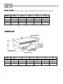
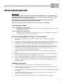
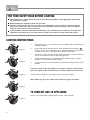
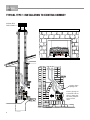
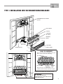
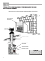
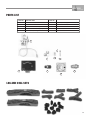
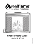
®
MAGIGLO SERIES
INSTALLATION & OPERATING MANUAL
The Magiglo series of decorative fires are suitable to be installed into a
masonry or approved prefabricated fireplace and are designed to
operate with Natural and Propane gases only. Approval Number 6094.
VERSION 7
WARRANTY
Provided your Real Flame gas burner is installed in strict accordance with our installation instructions, the
burner is unconditionally guaranteed for twelve months from date of purchase.
This unconditional warranty covers parts and labour at our discretion taking into consideration normal
wear and tear and does not cover fires installed in outdoor settings.
INSTALLATION NOTICE
The installation of this appliance is only to be carried out by an authorised person in accordance
with the Manufacturer’s Instructions, local gas fitting regulations, AG601 installation code for gas
burning appliances and any other relevant statutory regulations.
In all cases the installation of this appliance shall meet the requirements as set out in AS5601/AG601.
NOTE: A slight smell may be apparent for the first few hours of use. This is due to the heat
resistant paint curing. It is recommended to open windows in the room for the first lighting of the
fire. In some instances a slight discolouration may occur inside the firebox. This is a normal
condition and is not covered by warranty.
IMPORTANT SAFETY NOTICE
DO NOT PLACE ARTICLES ON OR AGAINST THIS APPLIANCE.
DO NOT USE OR STORE FLAMMABLE MATERIAL NEAR THE APPLIANCE.
DO NOT SPRAY AEROSOLS IN THE VICINITY OF THIS APPLIANCE WHILST IT IS IN OPERATION.
CARE MUST BE TAKEN TO ENSURE THAT ANY RETURN AIR REGISTER OR EXHAUST SYSTEM
DOES NOT ADVERSLEY AFFECT THE OPERATION OF THE APPLIANCE OR DRAUGHT OF
CHIMNEY OR FLUE.
VENTILATION REQUIREMENTS
Permanent ventilation of the room where the fire is to be situated is essential while fire is in operation.
The room must have a minimum cross sectional area of 40,000sq mm of effective ventilation.
WARNING
This firebox has a naked flame, care should be taken when it is operating if children or the infirm
are in close proximity. A safety screen is recommended if constant supervision is not possible.
2
CONTENTS
Contents ..................................................................................................................3
Data Plate.................................................................................................................4
Dimensions ..............................................................................................................4
Installation Instructions ............................................................................................5
Lighting Instructions ................................................................................................6
Commissioning Procedure ......................................................................................7
Typical Type 1 Installation to existing chimney .......................................................8
Type 1 Installation into Victorian/Federation grate..................................................9
Typical Type 2 Installation of Prefabricated Fire Box into existing chimney.........10
User Instructions ....................................................................................................11
Troubleshooting .....................................................................................................11
Conversion details .................................................................................................12
Parts List ................................................................................................................13
Real Flame contact information.............................................................................16
3
DATA PLATE (Affixed to the base of the unit for reference to gas pressure & consumption)
Model
320
360
400
540
NG
750
NG
LPG
NG
LPG
NG
LPG
Injector
2.4
1.2
2.5
1.3
2.4
1.3
LPG
MJ / HR
24
20
26
23
28
23
37
31
39
36
P.T.P.
0.8
2.7
0.8
2.7
0.8
2.7
0.8
2.6
0.64
2.55
2x2.2 2x1.1
NG
LPG
2x2.5 2x1.2
DIMENSIONS
Model
320
360
400
540
750
DBL
A
165
165
165
150
150
150
B
320
360
400
540
750
540
C
120
120
210
210
210
280
All dimensions in mm. Measurements exclude skirt and control knob.
4
INSTALLATION INSTRUCTIONS
IMPORTANT
This product is fitted with an OXYGEN DEPLETION SYSTEM which is an INTEGRAL PART
OF THE PILOT. You must maintain the correct pressure for the oxygen depletion system to
operate correctly (see data plate on page 4).
When checking gas pressure at the appliance ALL OTHER GAS APPLIANCES IN
PREMISES MUST BE OPERATING AT THE SAME TIME.
Failure to have correct pressure may result in unit cutting out intermittently.
TYPE OF INSTALLATIONS
TYPE 1. Magiglo Gas Log/Coal Set
Installed into masonry built fireplace intended to burn wood using the masonry chimney
to remove waste products.
TYPE 2. Magiglo Gas Log/Coal Set
Installed in conjunction with a prefabricated firebox into an existing fireplace using the
masonry chimney to remove waste products.
LOCATION REQUIREMENTS FOR TYPE 1 & 2 INSTALLATIONS
1.
The fireplace must be built in accordance with the building regulations for masonry
chimneys.
2.
The fireplace must be sufficiently deep enough to fully accommodate either the Gas
Log/Coal Set or a firebox fitted with a Gas Log/Coal Set in order that no fumes can escape
into the room. DO NOT ignore the depth of the lintel over the fireplace opening.
3.
It is imperative that the chimney or flue operates correctly and also does not subject the
living area to spillage of combusted products. The flue or chimney should be tested and
proven to have an adequate updraught sufficient to remove all waste products of
combustion. (Refer to Commissioning Procedure).
4.
Chimney dampers, baffles or restrictive plates must be removed or permanently fixed
open.
5.
An AGA approved flue cowl with a minimum cross sectional area of the following shall be
fitted to every masonry chimney - 40,000sq mm (225mm dia).
6.
If using a prefabricated firebox, the firebox must be sealed to the masonry or brickwork.
7.
Permanent ventilation of the room where the fire is to be situated is essential while fire is in
operation. The room must have a minimum cross sectional area of 40,000sq mm of
effective ventilation.
BURNER INSTALLATION
1.
Select the Magiglo series burner which best compliments your fireplace size.
2.
Locate your gas fire into the rear of the fireplace or prefabricated fire box fixing to base or
grate by location lugs on burner.
3.
It is preferable for the gas line to be brought into the rear of fireplace, therefore concealing
pipe work.
4.
If installing the burner into an existing grate, remove that part of base of grate so that
controls are on underside of grate.
5.
Connect gas line to burner connection using 1/2˝ flared copper union supplied.
5
FOR YOUR SAFETY READ BEFORE LIGHTING
The appliance has a pilot which must be lit using the piezo ignition, when lighting the pilot follow
the instructions exactly.
Before lighting the appliance check for gas leaks.
Use only your hand to push in and turn the gas control knob, never use tools. If the knob will not
push in or turn by hand, don’t try to repair it, call a qualified service technician. Force or attempt
to repair may result in a fire or explosion.
If the controls have been underwater, immediately call a qualified service technician to inspect the
appliance and replace any part of the control system and fan that has been immersed in water.
LIGHTING INSTRUCTIONS
Figure 1
Figure 2
1.
To light the pilot, press in and turn the gas control knob anticlockwise to
the pilot position.
2.
Keep knob depressed and turn the knob anticlockwise toward the
until you hear a click. If the pilot lights, continue to depress knob for 20
seconds and release. If pilot goes out repeat the procedure.
3.
To light the burner, turn the control knob to the flame setting. The burner
can be set anywhere between low and high flame.
4.
To turn the burner off, turn the control knob clockwise to the “PILOT”
position. This will leave the pilot burning.
5.
To turn off the burner and the pilot, turn the knob clockwise to the “OFF”
position.
If you are unable to get the appliance to operate correctly, contact either
your sales agent or the manufacturer (see contact details on back cover).
Figure 3
Test operation of appliance and fully instruct user before leaving.
Note: Check gas pressure. Refer to Data Plate on page 4 for details.
Figure 4
TO TURN OFF GAS TO APPLIANCE
Push in gas control knob slightly and turn to the “OFF” position.
Figure 5
6
COMMISSIONING PROCEDURE
Once the fire is installed and operational the installer must check for spillage. Carry out the
lighting procedure and turn the fire to high. Allow to warm up for 10 minutes and then using a
smoke match set 25mm down and 25mm inside of the fire opening run the match across the
width of the opening to check that all of the smoke is drawn away.
Repeat the test with doors and windows to the premises open and closed, and with any extractor
fans in the same room or adjacent rooms running on high. The fire should continue to clear its
combustion products. Also operate any other flued appliances in the same or neighbouring
rooms and ensure they continue to function satisfactorily as multiple flues can work against one
another.
If spillage is detected during this procedure it could indicate a faulty flue or lack or ventilation. If
the problem cannot be rectified immediately, disconnect the appliance, and advise the customer
not to use the appliance until the problem has been resolved.
The customer should always be advised of the need for regular servicing and checks to ensure
the continued clearance of combustion waste products.
NOTE: Care must be taken to ensure that any return air register exhaust system does not
adversely affect the operation of the appliance or draught of chimney or flue.
WARNING
“DO NOT place articles on or against this appliance.“
“DO NOT use or store flammable materials near this appliance.”
“DO NOT spray aerosols in the vicinity of this appliance while it is in operation.
7
TYPICAL TYPE 1 INSTALLATION TO EXISTING CHIMNEY
225mm DIA
GAS COWL
TYPICAL TYPE 1 INSTALLATION TO
EXISTING CHIMNEY
OFF
PI
T
LO
Smoke match
spillage test.
Ensure gas log fire
is set back into fire
place in order that
no waste products
come into the
room.
8
TYPE 1 INSTALLATION INTO VICTORIAN/FEDERATION GRATE
EDWARDIAN/VICTORIAN
GRATE
AIR TUBES
COALS
CERAMIC
BLANKET
BURNER
PORT
CUT OUT
SECTION
CONTROL
BASE GRATE
FRONT IRON
COAL PLACEMENT
Place Air Tubes 5mm behind Burner Port and
space evenly. (cut to size if too long).
AIR TUBES
5mm GAP
BURNER
HOUSING
BURNER
PORT
Place base layer of coals as above and
randomly stack remainder allowing for gaps.
PI
L
CONTROLS ON UNDER SIDE OF BASE GRATE
OT
OFF
IMPORTANT:
ALL AIR GAPS ON THE
UNDERSIDE OF THE BASE GRATE
MUST BE SEALED
9
TYPICAL TYPE 2 INSTALLATION OF PREFABRICATED FIRE BOX
INTO EXISTING CHIMNEY
FOR INSTALLATION OF FIRE BOX REFER TO MANUFACTURER’S SPECIFICATIONS.
SEAL FLANGE TO
BRICKWORK
OFF
PI
L
225mm DIA
GAS COWL
OT
EXISTING CHIMNEY
SEAL FLANGE TO
BRICKWORK
CONVECTION BOX
MAGIGLO GAS SET
ATTENTION
ATTENTION:
This is a guide only. Installation
This is a guide only. Installation
of Fire
Box
of Fire Box
must
bemust
carried out
be carried out to manufacturers
specifications.
to manufacturers specifications.
10
USER INSTRUCTIONS
1.
Your Magiglo Gas Log/Coal Set will have been installed by an authorised person in
accordance with the Installation and Service Instructions. If you are technically minded you
will increase your knowledge of your fire by reading through these Instructions
2.
Initially your Magiglo may burn with a slightly blue flame which part of the protective
coating on the coal and logs burn off. A slight smell my also be apparent at this stage.
After an hour or so the fire will have settled down and will therefore burn with a yellow
flame producing a little soot. The soot deposit enhances the real effect and is exactly the
same as an authentic fire.
3.
As with all gas appliances, your Magiglo should be regularly serviced. We would
recommend once each year. The name and address of your service technician can be
obtained from your Real Flame stockist. The routine to be followed by the engineer can be
found under Service Instructions; contained within this leaflet.
4.
For safe operation of your Magiglo the following annual checks should be carried out.
- Confirm that the chimney remains clear and unobstructed and there has not been a
build-up of soot which would necessitate the chimney being swept.
- Confirm that the room ventilation remains adequate and that all vents are free of
obstruction.
TROUBLESHOOTING
Symptom
Corrective Action
Pilot won’t light
1. Pressure too low. Set to correct pressure.
2. Check for spark at electrode if none, check lead connection. If not solved
replace electrode.
Pilot lights but does not
stay on.
Light pilot and keep knob depressed for 30 seconds before
releasing. If pilot does not stay on, replace thermocouple.
Main flame goes out or
very little flame.
1. Check for correct pressure.
2. Check for faulty thermocouple.
3. Excessive draught can cause flame to extinguish.
WARNING
Magiglo burn with a real flame which should be treated with same respect as any naked
flame. A fireguard should be used for the protection of children and the elderly.
11
CONVERSION DETAILS
PROPANE TO NATURAL GAS
Parts Required
Description
PART No.
1
3/8˝ male x 1/2˝ male Hex Nipple
05
2
1/2˝ SC-75 Regulator
02
3
1/2˝ male x 1/2˝ Copper Union
04
4
Natural gas Oxy Pilot Assembly
03N
5
Natural gas Main Burner Injector
(Refer to data plate for correct size)
010
Procedure
1.
Remove connection fitting from control valve and replace with 3/8˝ male x 1/2˝ male hex
nipple.
2.
Fit regulator to hex nipple.
3.
Fit 1/2˝ male x 1/2˝ copper union regulator.
4.
Remove pilot assembly cover and remove pilot assembly disconnecting thermocouple
pilot tube and electrode lead and replace with natural gas pilot assembly and reconnect.
5.
Remove main burner injector by loosening grub screw in boss and removing injector stem
holder from boss and change to correct size natural gas injector.
NATURAL GAS TO PROPANE
Parts Required
Description
1
3/8˝ male x 1/2˝ Copper Union
PART No.
-
2.
LPG Oxy Pilot Assembly
03P
3.
Main Burner Injector
(Refer to data plate for correct size)
010
Procedure
12
1.
Remove regulator complete with 1/2˝ connection and 3/8˝ x 1/2˝ hex nipple from control
valve.
2.
Fit 3/8˝ male x 1/2˝ copper union directly into control valve.
3.
Remove pilot cover and pilot assembly disconnecting thermocouple, pilot tube and
electrode lead and replace with L.P.G. pilot assembly and reconnect.
4.
Remove main burner injector by loosening grub screw in boss and removing injector stem
holder from boss and change to correct size L.P.G. injector.
PARTS LIST
PART No.
DESCRIPTION
PART No.
01
BM 733 Control Valve
05
1/2˝ to 3/8˝ Hex Nipple
02
Regulator SC-75
06
5/16˝ 90O Union Elbow
S.I.T. ODS Pilot Assembly (Natural Gas)
07
1/4˝ Nut and Olive
S.I.T. ODS Pilot Assembly (Propane Gas)
08
Injector Holder Stem
1/2˝ Male to 1/2˝ Copper Union
09
Injector
03N
03P
04
3
9
6
1
7
8
4
5
2
LOG AND COAL SETS
13
14
15
REAL FLAME PTY LTD
ABN 76 006 311 155
Head Office/Factory/Showroom
1340 Ferntree Gully Rd.
Scoresby Vic 3179
Ph: (03) 8706 2000 Fax: (03) 8706 2001
E-mail: [email protected]
Richmond - VIC Showroom
300 Swan St.
Richmond Vic 3121
Ph: (03) 9428 4443 Fax: (03) 9428 4445
Geelong - VIC Showroom
1/2A Gordon Avenue.
Geelong West Vic 3218
Ph/Fax: (03) 5229 0844
E-mail: [email protected]
Sydney - NSW Showroom
654 Pacific Highway.
Chatswood NSW 2067
Ph: (02) 8905 0189 Fax: (02) 8905 0192
E-mail: [email protected]
Miranda - NSW Showroom
36 Kareena Rd
Miranda NSW 2228
Ph: (02) 8513 6202 Fax: (02) 9520 1974
E-mail: [email protected]
Adelaide - SA Showroom
173 -175 Magill Rd.
Norwood SA 5067
Ph: (08) 8132 0371 Fax: (08) 8132 1687
E-mail: [email protected]
Miton - QLD Showroom
46 Douglas St,
Milton QLD 4064
Ph: (07) 3368 2011
Perth – WA Showroom
47-53 McDonald St East,
Osborne Park WA 6017
Ph: (08) 9444 9900 Fax: (08) 9444 9800
Fyshwick – ACT Showroom
88 Wollongong St,
Fyshwick ACT 2609
Ph: (02) 6280 5522