1
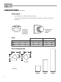
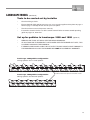
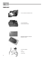
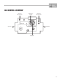
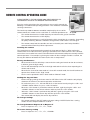
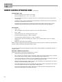
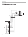
LANDSCAPE® BALANCED
FLUE SPACE HEATER
INSTALLATION & OPERATING MANUAL
The Landscape 1000 & 1600 are approved to be installed as a zero
clearance firebox and are designed to operate on Natural Gas and
Propane (LPG) gases ONLY. Approval Number GMK 10056.
VERSION 19
WARRANTY
Provided your Real Flame gas fire is installed in strict accordance with our installation instructions, the
firebox is unconditionally guaranteed for ten years and all other parts for twelve months from date of
purchase.
This unconditional warranty covers parts and labour at our discretion taking into consideration normal wear
and tear and does not cover fires installed in outdoor settings.
WARNING
The “Landscape 1000 & 1600” have a primary safety glass fitted in front of the glass door. This safety glass
is fitted to these appliances to reduce the risk of injury from burns and at no time should this glass be
permanently removed.
For protection of young children or the infirm, a secondary guard is required.
WARNING
The outer glass panel gets extremely hot! Precaution should be taken and young children
supervised at all times when heater is operating.
INSTALLATION NOTICE
The installation of this appliance is only to be carried out by an authorised person in accordance
with the Manufacturer’s Instructions, local gas fitting regulations, AS5601-2004 installation code
for gas burning appliances and any other relevant statutory regulations.
Do not modify this appliance.
In all cases the installation of this appliance shall meet the requirements as set out in
AS5601-2004.
NOTE: A slight smell may be apparent for the first few hours of use. This is due to the heat resistant
paint curing. It is recommended to open windows in the room for the first lighting of the fire. In some
instances a slight discolouration may occur inside the firebox. This is a normal condition and is not
covered by warranty.
IMPORTANT SAFETY NOTICE
DO NOT PLACE ARTICLES ON OR AGAINST THIS APPLIANCE.
DO NOT USE OR STORE FLAMMABLE MATERIAL NEAR THE APPLIANCE.
DO NOT SPRAY AEROSOLS IN THE VICINITY OF THIS APPLIANCE WHILST IT IS IN OPERATION.
CARE MUST BE TAKEN TO ENSURE THAT ANY RETURN AIR REGISTER OR EXHAUST SYSTEM
DOES NOT ADVERSLEY AFFECT THE OPERATION OF THE APPLIANCE OR DRAUGHT OF
CHIMNEY OR FLUE.
2
CONTENTS
Contents ..................................................................................................................3
Data Plate .................................................................................................................4
Zero Clearance introduction ....................................................................................5
Dimensions Landscape 1000 ..................................................................................6
Dimensions Landscape 1600 ..................................................................................7
Terminations .............................................................................................................8
Timber frame installation..........................................................................................9
Vertical & horizontal venting installation ................................................................12
Tests to be carried out by installer .........................................................................13
Pebble set up .........................................................................................................13
Servicing and maintenance ...................................................................................14
Parts list ................................................................................................................16
Gas control assembly ............................................................................................17
Flue termination (cowls) regulations .....................................................................18
Remote control operating guide ............................................................................19
Electrical diagram ..................................................................................................22
Troubleshooting .....................................................................................................24
Real Flame contact information .............................................................................28
3
DATA PLATE (Affixed to the base of the unit for reference to gas pressure & consumption)
MODEL
LANDSCAPE 1000
GAS TYPE
NATURAL GAS @ 0.8 kPa
TEST PRESSURE POINT (HIGH)
INJECTOR SIZE
3 X 2.3mm
GAS CONSUMPTION
41Mj/h
LPG @ 2.6 kPa
TEST PRESSURE POINT (HIGH)
INJECTOR SIZE
3 X 1.1mm
GAS CONSUMPTION
41Mj/h
NATURAL GAS @ 0.40 kPa
TEST PRESSURE POINT (LOW)
INJECTOR SIZE
3 X 2.3mm
GAS CONSUMPTION
28Mj/h
LPG @ 0.90 kPa
TEST PRESSURE POINT (LOW)
INJECTOR SIZE
3 X 1.1mm
GAS CONSUMPTION
28Mj/h
APPROVAL NO: GMK10056
SERIAL NUMBER:
WEIGHT 132 KG
DATE OF MANUFACTURE
MODEL
LANDSCAPE 1600
GAS TYPE
NATURAL GAS @ 1.00 kPa
TEST PRESSURE POINT (HIGH)
INJECTOR SIZE
4 X 2.75mm
GAS CONSUMPTION
51Mj/h
LPG @ 2.6 kPa
TEST PRESSURE POINT (HIGH)
INJECTOR SIZE
4 X 1.0mm
GAS CONSUMPTION
51Mj/h
NATURAL GAS @ 0.40 kPa
TEST PRESSURE POINT (LOW)
INJECTOR SIZE
4 X 2.75mm
GAS CONSUMPTION
31Mj/h
LPG @ 1.50 kPa
TEST PRESSURE POINT (LOW)
INJECTOR SIZE
4 X 1.0mm
GAS CONSUMPTION
38Mj/h
APPROVAL NO: GMK10056
SERIAL NUMBER:
DATE OF MANUFACTURE
4
WEIGHT 195 KG
LANDSCAPE MODEL
INTRODUCTION
The Real Flame “Landscape” is a ribbon burner space heater for use with Natural Gas Aus & NZ
and Propane.
The Real Flame warranty will be voided by, and Real Flame disclaims any responsibility for the
following actions:
•
Modification of the space heater and/or components including balanced flue assembly or
glass door.
•
Use of any component part not manufactured or approved by Real Flame in combination
with this “Landscape” fireplace system.
•
Installation other than as instructed in this manual.
CAUTIONS
•
Due to its high operating temperature, the appliance should be located out of traffic and
away from furniture and draperies.
•
Children and adults should be alerted to the hazards of the high surface temperature, which
could cause burns or clothing ignition.
•
Young children should be carefully supervised when they are in the same room as the
appliance.
•
Clothing or other flammable materials must not be placed on or near the appliance.
SELECTING YOUR APPLIANCE LOCATION
Your appliance may be installed in any location that is free of air conditioning ducts, electrical
wiring and plumbing. Safety, as well as efficiency of operation, must be considered when
selecting the heater location. Try to select a location that does not interfere with room traffic and
offers access for the Balanced Flue terminal installation. Refer to AS5601-2004 for minimum
clearances for Balanced Flue termination.
WARNING
When this appliance is installed directly on tile or other combustible materials other than wood
flooring, the appliance should be installed on a metal or wood panel extending the full width and
depth of the appliance.
5
DIMENSIONS
Landscape 1000
A
B
C
855
467
I
J
K
755
505
65
D
E
F
G
H
415
270
150
20
L
M
N
30
178
190
1000 1160
50mm Stand Offs
100mm
Stand Offs
25mm Stand Offs
Fixing
channel
for plaster
Lifting
Handles
Trim
Gas
70mm
90mm
Power
Landscape 1000 Trim
6
A
B
C
1100
467
50
DIMENSIONS
Landscape 1600
Trim
Gas
A
B
C
855
467
G
H
I
150
20
755
D
E
F
415
270
J
K
L
M
N
700
65
30
178
190
1600 1760
Gas
Power
60mm
115mm
Landscape 1600 Trim
A
B
C
1700
467
50
7
LANDSCAPE MODEL (continued)
Cowl types
•
The Landscape is a balanced flue space heater.
•
It can be installed with the flue terminating with a horizontal or vertical cowl to suit the
application.
Vertical top
termination
Horizontal rear
termination
Vertical top
termination
RF/HZ
Flue
90° Bend
45° Bend
A
B
A
B
180
265
370
260
200
225
315
315
270
270
300mm
600mm
Model
Inner
Outer
1000
100
1600
150
Flue Components
A
A
B
B
45° Bend
90° Bend
8
1200mm
LANDSCAPE MODEL (continued)
Timber Frame Installation Procedure
Step 1
Construct the base for the unit. Ensure base is adequate for the weight of the fire.
Step 2
Call for delivery of the unit, position on the base and fit off gather, flues and termination. Connect
gas and power.
Back of unit to
centre of flue
(Excluding 25mm
standoff)
Vertical Termination
1000 = 160
1600 = 122
C
Termination outside
(Horizontal shown)
FLUE
GATHER
Base of unit to
centre of flue
1000 = 1695
1600 = 1637
POWER
GAS
9
LANDSCAPE MODEL (continued)
Timber Frame Installation Procedure
Step 3
Construct the frame
around the fire as per
drawing, taking note of
required clearances.
(See page 11)
PLASTER
Step 4
Sheet plaster and finish
remembering to run plaster
beyond stud and behind trim.
TRIM
Step 5
Commission fire as per
page 13.
10
LANDSCAPE MODEL (continued)
Landscape 1000 & 1600
Timber Frame Installation Dimensions
D
(Recommended only)
FLUE
GATHER
515
A
VIEWING AREA*
TRIM
Plaster to run
beyond stud and
behind trim
190
B
*Viewing area for 1000 is
1000mm x 370mm
Viewing area for 1600 is
1600mm x 370mm
C
Frameout Dimensions (in mm)
NOTE: Ensure frame is suitable for fire weight.
MODEL
1000
1600
Min 50mm
clearance
Trim
NOTE
Plasterboard to run beyond stud as shown,
and to go behind trim.
A
B
C
D
960
960
1260
1860
475
475
1800
2400
CLEARANCES FROM
COMBUSTIBLES
Floor
Sides
Top
Flue Outer
Front
Back
0 mm
50 mm
100 mm
50 mm
25 mm
25 mm
11
LANDSCAPE ZERO CLEARANCE MODEL (continued)
INSTALLATION OF VERTICAL & HORIZONTAL FLUING
Vertical terminations must be installed with the following clearances:
•
Minimum of 500 mm from the nearest part of the roof (Measurement is taken from the
bottom of the termination).
•
Minimum of 1500 mm from any mechanical air inlet.
•
Minimum of 500 mm from any building structure or obstruction facing the termination.
•
Maximum vent height is 4.5 meters from the base of the unit.
•
Minimum clearances 50mm from vent to all combustible materials must be maintained.
6.2 m
NOT TO SCALE
0.3 m min
min 3.6 m
max 4.5m
3m
max
2.4 m
Note: 85mm baffle for 1600 or 40mm baffle for 1000 required.
The required baffle will be fitted to the unit when dispatched.
Horizontal
Vertical
BALANCED FLUE TERMINATION LOCATION
This section is used to determine where your Balanced Flue termination will be located.:
•
Flue terminations shall not be recessed in walls or sidings.
•
EXTREMELY IMPORTANT: In heavy snow areas take extra care to prevent blocking flue
termination with snow removal equipment.
•
Flue gases exiting flue terminals are very hot and must not be restricted to assure fireplace
combustion is not affected.
•
Do not place, build any obstruction, plant any bushes or for any reason attempt to conceal
the flue termination. To do so will affect the operation of the fireplace and may be
hazardous.
•
This unit must always vent directly to outdoors.
CAUTIONS AND REQUIREMENTS
All flueing must maintain a clearance of 50mm from combustible materials.
12
NOTE: It is imperative for satisfactory operation of the “Landscape” space heater that no flueing
components be modified in any way. All components have been manufactured to eliminate the
need for modification when properly selected and installed.
LANDSCAPE MODEL (continued)
Tests to be carried out by installer
•
Check unit for gas leaks.
•
Ensure that both high and low pressures are set as per the appliance data plate on page 4.
Refer to page 17 for adjustments and test pressure points
•
Turn the unit on to ensure it operates correctly.
•
Instruct the customer on the use of the remote control. Refer to remote control operating
guide on pages 19, 20 and 21.
Set up for pebbles in Landscape 1000 and 1600
(Optional)
•
PEBBLES ARE TO BE SET UP AS PER THE BELOW DRAWINGS.
•
AT NO STAGE ARE THE PEBBLES TO BE PLACED OVER THE BURNER CUT OUTS, THIS
IS CLEARLY SHOWN IN THE DRAWINGS.
•
IF PEBBLES ARE PLACED OVER THE CUT OUTS THIS MAY CAUSE SLIGHT DAMAGE TO
THE BURNER AND AS SUCH THE BURNER WILL NOT BE COVERED BY WARRANTY.
Landscape 1600 pebble configuration
32 large pebbles and 17 small pebbles
Landscape 1000 pebble configuration
Pebbles must not be placed over burner cutouts
20 large pebbles and 20 small pebbles
13
SERVICING AND MAINTENANCE
To follow when servicing,
removing fan or changing
valve or control modules.
IMPORTANT: POWER MUST BE
ISOLATED PRIOR TO CARRYING
OUT THE SERVICE/MAINTENANCE.
SERVICE/MAINTENANCE ONLY TO
BE CARRIED OUT BY AN
AUTHORISED PERSON.
DO NOT MODIFY THIS
APPLIANCE
2. Remove front safety glass
1. Remove the trim
3. Prise up air intake panel
e air intake panel
14
4. Lift out air intake panel
5. Unscrew rear glass door
6. Lift out rear glass door
7. Remove burner top plate
SERVICING AND MAINTENANCE
(continued)
8. Remove burner
9. Remove bottom of burner tray, fan is
then exposed and may be serviced or
removed
To service or change gas valve
or control modules, the
process is the same as steps
1 to 3.
After carrying out service or
replacing parts, reverse the
above processes to reinstate
the unit.
Prior to lighting ensure there
are no gas leaks.
FOR YOUR SAFETY READ BEFORE LIGHTING
• Check the appliance for gas leaks
• Check that all electrical connections are secure
• Check that the power to the unit has been turned on
MAINTENANCE
It is recommended that you have your landscape installation inspected yearly
including a visual check of the flue system and flame pattern.
15
PARTS LIST
SIT 845 SIGMA GAS CONTROL VALVE
SIT 579 ELECTRONIC
FLAME CONTROL DEVICE
MILLENIUM THERMOSTAT REMOTE
CONTROL SYSTEM
1
SIT PILOT ASSEMBLY
2
1. Pilot
2. Pilot Tube
3
16
3. Burner Tube
GAS CONTROL ASSEMBLY
Inlet Test
Pressure Point
Adjustment
for High
Gas Inlet
Outet Test
Pressure Point
Gas Outlet
Adjustment
for Low
17
LANDSCAPE FLUE TERMINATION (COWLS) REGULATIONS
Balanced Flue
18
REMOTE CONTROL OPERATING GUIDE
PLEASE REFER TO THE MILLENIUM 7000 SERIES MANUAL ON
OUR WEBSITE SHOULD YOU REQUIRE FURTHER DETAIL.
To assist service technicians who may not have access to this manual, the
following is an abbreviated operating procedure. This should be read before
servicing commences.
The Landscape 1000 & 1600 are controlled completely by the use of the
remote control; this remote can be used either as a manual operation or an auto operation.
•
The remote thermostat uses radio frequency to transmit to the gas/fan controller.
•
The remote thermostat has a LCD display
•
The remote thermostat uses 2 off “AA” batteries which should last for 12 months. (Depending
on quality of battery.) Batteries should be changed when smoke alarms are changed.
•
The remote control and the controller are non-serviceable parts and if faulty should be
returned to Real Flame Pty Ltd for replacement.
Locating the remote
The remote houses the thermostat that controls the heat output of the fire. When storing the
remote either on its wall bracket or by placing it somewhere in the room where the fire is located,
ensure there are no other heat sources that will affect the thermostats ability to accurately read the
room temperature. For example, by placing the remote in direct sunlight or under a cushion, the
fire may turn down or off before the room reaches the set temperature.
Factory Set Features
•
When turned on the fire will always start on the low setting and remain on low for 3 minutes,
it will then go to the high setting.
•
The fan will automatically come on in the high mode after the fire has been operating for 3
minutes 20 seconds.
•
When the fire shuts off on auto mode or is shut off in manual mode, the fan will continue to
operate for 3 minutes in the “High” mode.
•
The fire can be operated in either “Auto” mode or “Manual” mode.
Setting the day and time
•
Before changing settings the heater must be OFF. When in the OFF mode the only display
shown on the remote is the room temperature and the time.
•
To set the time press <T>, the hour will flash, set the correct hour by using the <UP> and
<DOWN> button. When set, press <OK> to confirm.
•
When the <OK> button is pushed the minutes will flash, again by using the <UP> and
<DOWN> buttons set the correct minutes and then push the <OK> button.
•
When the <OK> button is pushed the day will flash, again by using the <UP> and
<DOWN> buttons set the correct day and then push the <OK> button.
•
Your remote will now display the correct day and time.
To change settings
•
The remote must be in the OFF mode to change settings. NOTE: Each of the 3 setting
modes must be completed within 2 seconds.
To change between Degrees C to Degrees F
•
Press in sequence <P>, <T>, <T>, <A/M>
To restore factory setting
•
Press in sequence <P>, <T>, <T>, <DOWN>
19
REMOTE CONTROL OPERATING GUIDE
(continued)
Teaching RF code
•
Ensure the power to the heater is turned off.
•
Press in sequence <P>, <T>, <T>, <UP>
•
The LCD diplay will show “CL” (Code Learn) for 2 seconds then return to the normal OFF
state display.
•
During this time a special code will be transmitted by the RF thermostat to the control unit,
causing the control unit to learn its ID.
•
CAUTION: The thermostat has already been programmed with a unique code. Do not
attempt to teach the RF thermostat ID code unless instructed by the manufacturer.
To program
•
Press <P>
•
“PD” will appear at the top of the display screen. And “MO” will flash.
•
Press <OK>
•
Time will flash and “P1” will appear in the screen.
•
Set wake up time and press <OK> to confirm.
•
Set temperature required and press <OK> to confirm.
•
Repeat above steps for remaining “P2” (Away), “P3” (Coming Home) and “P4” (Sleep)
programs.
•
Repeat all of the above for each day.
When setting the programs have the remote near the unit to ensure the remote can communicate
with the control (Located in the bottom of the heater.)
The Landscape will operate through the remote either in Manual Mode or Auto Mode, below is a
sample of each:
Example of Manual Operation
Set the thermostat to desired Set temperature e.g. 26°C.
20
•
The flame will start on low, with the fan off.
•
After 3 minutes, the flame changes to the High setting, if the temperature is 23.5°C or lower.
The fan will switch on High 3 minutes and 20 seconds after the flame is lit.
•
As the temperature rises above 23.5°C, the modulating valve will decrease the gas level one
step every 0.5° above 23.5°. The fan will continue to operate on High.
•
When the room temperature reaches 26.5°C, the modulating valve will operate at its lowest
setting. The fan will switch to Low speed.
•
If the room temperature were to rise above 29°C,the flame will be extinguished. The fan will
run on for another 3 minutes on High before shutting down.
•
If the room temperature then drops down to 26° or lower, the flame will again be lit, and
then the fan will begin after the flame-on delay.
REMOTE CONTROL OPERATING GUIDE
(continued)
In Auto mode, the RF thermostat will control the flame and the fan according to the programmed
times and temperature. The flame can be programmed to turn on or off, or change the required
temperature.
The switch off and on sequence operate as per manual operation, detailed above.
Example of Auto Operation
Set the thermostat to Monday;
Turn off at 8.00 am and set temperature of 25°C;
Lower temperature at 9.00 am with set temperature at 15°C.
•
At 8.00 am on Monday, the flame will start on Low, with fan off (if flame was already off)
•
After 3 minutes, the flame changes to highest setting, if room temperature is 22.5° or lower.
The fan will switch on High after 3 minutes and 20 seconds after the flame was lit.
•
As the temperature rises above 22.5°, the modulating valve will decrease the gas level one
step for every 0.5° above 22.5°. The fan will continue to operate on High.
•
When the room temperature reaches 22.5°, the modulating valve will operate at its lowest
setting. The fan will switch to Low speed. The flame will remain lit as long as the room
temperature is 28° or lower.
•
If the room temperature were to rise above 28°, the flame will be extinguished. The fan will
run for further 3 minutes on High before shutting down.
•
If the room temperature then drops down to 25° or lower, the flame will again be lit, and the
fan will begin after the flame-on delay.
•
At 9.00 am on Monday, the required room temperature is now only 15°C.
•
If the room temperature is above 18°, then the flame will be extinguished, with the fan
operating for a further 3 minutes.
•
If however the room temperature were to be below 18° for whatever reason, the flame would
remain on together with the fan. The level of the flame, or speed of the fan, will depend how
far below the 18° is the room temperature.
WARNING
When the RF thermostat is in the “Auto” mode and the room temperature drops below the
minimum temperature, the fire and fan will come on and operate until the room temperature is 3°
above the minimum and then turn off, therefore:
•
The minimum temperature should be set at a temperature that is not likely to cause the fire
to continually turn on and off.
•
If leaving the house for an extended period, the RF thermostat should be turned “OFF”.
•
As long as the RF thermostat is in the “Auto” mode and the temperature goes below the
minimum set temperature, the fire will come on no matter what times are programmed into
the thermostat.
•
If you are unsure of the operation of the RF thermostat, please contact the manufacturer.
21
ELECTRICAL DIAGRAM - Landscape 1000
Modulating Coil
1 2
MD
1
2
3
4
5
6
7
8
9
CON9
Over Temp Switch
CON2
SIT Ignition Control
CON12
Fuse1
121110 9 8 7 6 5 4 3 2 1
Fan Motor
MD
Ignitor
Medium Speed
Low Speed
Neutral
Active
Neutral
NEUTRAL
ACTIVE LOW
MED
FAN SW
ACTIVE
PCB
HIGH
THERM
TH1 TH2
GAS
VALVE
MOD1 MOD2
22
ELECTRICAL DIAGRAM - Landscape 1600
Modulating Coil
1 2
Ignitor
MD
MD
1
2
3
4
5
6
7
8
9
CON9
Over Temp Switch
CON2
SIT Ignition Control
CON12
Fuse1
121110 9 8 7 6 5 4 3 2 1
Fan Motor 1
Fan Motor 2
Medium Speed
Low Speed
Neutral
Active
Neutral
NEUTRAL
ACTIVE LOW
MED
FAN SW
ACTIVE
PCB
HIGH
THERM
TH1 TH2
GAS
VALVE
MOD1 MOD2
23
TROUBLESHOOTING FOR LANDSCAPE
Problem
Possible Cause
Suggested Remedy
When the remote is activated
nothing happens
The remote is not talking to the receiver.
Reprogramme the remote to
the receiver (Refer Millennium
manual in installation manual).
The remote batteries are flat.
Replace the batteries.
The fire cuts off and won’t relight The over temp snap disc has
been activated.
Allow the fire to cool down and
then try to relight the fire. If the
fire fails to relight, contact the
manufacturer.
The fan will not come on
Possible caused by overheat
or electrical fault.
Contact the manufacturer.
Flame appears to be low
Pressure not set.
All pressures are set in the
factory at the time of
manufacture, however the
installing plumber mus make
sure the pressures are correct.
IF YOUR LANDSCAPE FIREPLACE STILL DOES NOT OPERATE CORRECTLY CONSULT YOUR DEALER.
ALL SERVICE AND REPAIRS SHOULD BE PERFORMED BY AN AUTHORISED AGENCY.
ALL SPARE PARTS AND OPTIONAL TRIM FINISHES ARE AVAILABLE FROM REAL FLAME PTY LTD.
24
25
26
27
REAL FLAME PTY LTD
ABN 76 006 311 155
Head Office/Factory/Showroom
1340 Ferntree Gully Rd.
Scoresby Vic 3179
Ph: (03) 8706 2000 Fax: (03) 8706 2001
E-mail: [email protected]
Richmond - VIC Showroom
300 Swan St.
Richmond Vic 3121
Ph: (03) 9428 4443 Fax: (03) 9428 4445
Dandenong - VIC Showroom
9 Lonsdale St.
Dandenong Vic 3175
Ph: (03) 9791 9285 Fax: (03) 9791 9662
Geelong - VIC Showroom
1/2A Gordon Avenue.
Geelong West Vic 3218
Ph/Fax: 5229 0844
E-mail: [email protected]
Sydney - NSW Showroom
654 Pacific Highway.
Chatswood NSW 2067
Ph: (02) 8905 0189 Fax: (02) 8905 0192
E-mail: [email protected]
Miranda - NSW Showroom
36 Kareena Rd
Miranda NSW 2228
Ph: (02) 8513 6202 Fax: (02) 9520 1974
E-mail: [email protected]
Adelaide - SA Showroom
173 -175 Magill Rd.
Norwood SA 5067
Ph: (08) 8132 0371 Fax: (08) 8132 1687
E-mail: [email protected]
Miton - QLD Showroom
46 Douglas St,
Milton QLD 4064
Ph: (07) 3368 2011
Perth – WA Showroom
47-53 McDonald St East,
Osborne Park WA 6017
Ph: (08) 9444 9900 Fax: (08) 9444 9800
Fyshwick – ACT Showroom
88 Wollongong St,
Fyshwick ACT 2609
Ph: (02) 6280 5522