1
LoadLifter 5000
Installing the LoadLifter5000 System
CAUTION
DANGER
YOUR VEHICLE MAY BE EQUIPPED WITH A REAR BRAKE PROPORTIONING VALVE.
ANY TYPE OF LOAD ASSIST PRODUCT COULD AFFECT BRAKE PERFORMANCE.
WE RECOMMEND THAT YOU CHECK WITH YOUR DEALER BEFORE INSTALLING
THIS TYPE OF PRODUCT. IF YOUR VEHICLE DOES NOT HAVE A REAR BRAKE
PROPORTIONING VALVE OR IS EQUIPPED WITH AN ANTI-LOCK TYPE BRAKE
SYSTEM, INSTALLATION OF A LOAD ASSIST PRODUCT WILL HAVE NO EFFECT ON
BRAKE SYSTEM PERFORMANCE.
COMPRESSED AIR CAN CAUSE INJURY AND DAMAGE TO THE VEHICLE AND PARTS
IF IT IS NOT HANDLED PROPERLY. FOR YOUR SAFETY, DO NOT TRY TO INFLATE THE
AIR SPRINGS UNTIL THEY HAVE BEEN PROPERLY SECURED TO THE VEHICLE.
GETTING STARTED
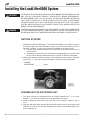
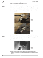
1. Determine the Normal Ride Height. The Normal Ride Height is the distance between
the bottom edge of the wheel-well and the center of the hub with the vehicle in the “as
delivered” condition. In some cases, Normal Ride Height is not perfectly level.
a. Remove unusual loads and examine your vehicle from the side to ensure it is on
a level surface.
b. If necessary (in cases where your leaf springs are sagging badly), use a jack to raise
the rear end so that the vehicle achieves the original “as delivered” ride height.
2. Measure the distance between the center of the hub and the bottom edge of the wheel
well (see fig. 1). This is the Normal Ride Height. Enter the measurement below:
NORMAL
RIDE HEIGHT: __________ inches
fig. 1
ASSEMBLING THE AIR SPRING UNIT
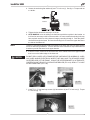
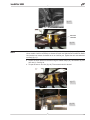
1. The upper brackets are designated “Left” and “Right” indicated by “L” or “R” on the
bracket. “L” for the driver side and “R” for the passenger side (fig. 2).
2. Install 90 degree air swivel fitting (D) to the top of the air spring. Tighten 1 and 1/2
turns.
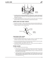
3. Align the right hand upper bracket (B2) with the mounting holes in the air spring and
install the 3/8” stud (L) in the outboard tapped hole with the short threaded portion into
the air spring (fig. 3).
4
MN-748