1
MISSION CRITICAL Air Conditioning Systems
M52 Microprocessor
User’s Guide
ClimateWorx International Inc.
M52UMCT2014.DOC 2014
14 Chelsea Lane, Brampton, Ontario, Canada L6T 3Y4
M52 Microprocessor User's Guide
2
M52UMCT2014.DOC 2014
M52 Microprocessor User's Guide
Table of Contents
Sequence of Operation ...................................................................................................................................................... 6
Phase Loss (OPTION):.................................................................................................. 6
Analogue and digital outputs for functions ................................................................... 6
DX Demand (Cooling) ................................................................................................... 6
Chilled Water................................................................................................................. 7
DX Demand (Dehumidification): .................................................................................. 7
Rapid Dehumidification Feature (Series 6 units only) .................................................. 7
Dual Cooling Units: ...................................................................................................... 8
Free Cooling Units: ....................................................................................................... 8
Reheat:........................................................................................................................... 9
Humidifier: .................................................................................................................... 9
PID .............................................................................................................................. 10
Internal Safety Controls .............................................................................................. 10
External Optional Safety Controls .............................................................................. 10
On/Off Control ............................................................................................................ 10
Back up Capability ...................................................................................................... 10
Note: On/Off mode: ..................................................................................................... 11
Powering Up / Powering Down ...................................................................................................................................... 12
The Control Panel ........................................................................................................................................................... 13
Banner line ................................................................................................................... 13
Active tab display area ................................................................................................. 13
Tab bar ......................................................................................................................... 13
Operating Status ............................................................................................................................................................. 14
Main Return Air Temperature & Humidity Readout ................................................... 14
Process Status Display ................................................................................................. 14
Network Address .......................................................................................................... 14
Alarm Icon ................................................................................................................... 15
Unit fan On/Off Icon .................................................................................................... 15
On/Off Mode Icon ........................................................................................................ 15
Co-Work™ Address Icon ............................................................................................. 16
Security ............................................................................................................................................................................ 17
Log-in Security ............................................................................................................. 17
Log-out Security ........................................................................................................... 18
Change Password ........................................................................................................ 18
M52UMCT2014.DOC 2014
3
M52 Microprocessor User's Guide
Alarms ..............................................................................................................................................................................20
Review Active Alarm Queue ........................................................................................20
Acknowledging Alarm..................................................................................................21
Clear Alarm Message ..................................................................................................21
Alarm Configuration....................................................................................................22
High Temperature Alarm note: ...................................................................................23
Historical Event Log .......................................................................................................................................................25
Timer On/Off Schedule ...................................................................................................................................................26
Review Timer On/Off Schedule ....................................................................................26
Programming the Timer On/Off Schedule ...................................................................27
Set Clock ......................................................................................................................27
Temperature and Humidity Log Graph .......................................................................................................................28
Settings .............................................................................................................................................................................29
Programming Settings .................................................................................................29
Settings Summary Version 473 (All units except Chilled Water).................................30
Settings Summary Glossary Version 473 (All units except Chilled Water) .................31
Settings Summary Version 491B2 (Chilled Water units only) .....................................33
Settings Summary Glossary Version 491B2 (Chilled Water units only)......................36
Test Mode .........................................................................................................................................................................39
Microprocessor Board Diagnostic ..............................................................................39
Digital I/O Board Diagnostic ......................................................................................41
Test Mode Unit on/off ..................................................................................................41
Sensor Calibration .......................................................................................................42
Sensor Calibration Sequence.......................................................................................43
Temperature .................................................................................................................43
Relative Humidity .........................................................................................................43
Data Re-initialization ..................................................................................................43
Co-Work™.......................................................................................................................................................................45
Settings Menu, Sensor mode:.......................................................................................46
Alarm Settings, Responses chart: ................................................................................47
Fault Finding ...................................................................................................................................................................50
4
M52UMCT2014.DOC 2014
M52 Microprocessor User's Guide
High Temperature Alarm ............................................................................................ 50
Low Temperature Alarm.............................................................................................. 50
High Humidity Alarm .................................................................................................. 51
Low Humidity Alarm ................................................................................................... 51
High Voltage Alarm..................................................................................................... 52
Low Voltage Alarm ...................................................................................................... 52
Low Airflow Alarm ...................................................................................................... 53
Filter Dirty Alarm........................................................................................................ 53
Fan Overload Alarm ................................................................................................... 54
Heater Overheat Alarm ............................................................................................... 54
Boiler Dirty Alarm ....................................................................................................... 55
High Pressure Alarm ................................................................................................... 56
Low Pressure or Short Cycling Alarm ........................................................................ 57
Appendix A: Electrical Schematic Diagrams ............................................................................................................... 58
M52UMCT2014.DOC 2014
5
M52 Microprocessor User's Guide
Sequence of Operation
The following is an outline of the operation of the unit. Not all units have all options.
1.
Unit powered
2.
ClimateWorx Banner appears and controller beeps three times.
3.
Microprocessor initializes Co-Work and runs self check.
4.
Random start timer activates
5.
Restart delay counts down
Phase Loss (OPTION):
On loss or cross of a phase of supply power the unit will shut down or display Phase Loss
alarm. You must acknowledge the alarm and correct the phase before the unit will restart.
6.
Blower starts (Blower runs continuously) when unit is in the ON position and when
Restart mode is set to Auto.
7.
Warm-up period begins to allow time for steady signal from sensors. Temp/Hum readings
flash on screen during warm-up.
8.
DX systems, crankcase heaters are energized when compressor is OFF through auxiliary
N/C contact on compressor contactor.
9.
Air cooled DX units with flooded condenser Low Ambient Control (LAC) N/C auxiliary
contact on compressor contactor energizes receiver heaters.
Analogue and digital outputs for functions
Cooling
0-10 vdc and 1 or 2 triac outputs
Heating
0-10 vdc and 1, 2 and/or 3 triac outputs
Humidifying
0-10 vdc and 1 triac output
Dehumidifying
0-10 vdc and 1 or 2 triac outputs
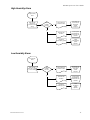
DX Demand (Cooling)
Cycles on compressors in stages 1 to 8 depending on number of units connected together with CoWork as demand for cooling increases from 0 to 100%.
Demand for compressor:
•
•
6
Compressor contactor receives signal from microprocessor. Positive Start timer (Pos. start
delay) starts and bypasses LP switch for cold start-up. When HP switch is closed the start
circuit is complete and the compressor starts.
N/C auxiliary contact on compressor contactor opens and de-energizes receiver heaters.
(Flooded Condenser LAC)
M52UMCT2014.DOC 2014
M52 Microprocessor User's Guide
N/C auxiliary contact on compressor contactor opens and de-energizes crankcase heater.
N/O auxiliary contact on compressor contactor starts remote condenser. (Air-cooled units only)
Low-pressure switch remains closed after Pos. start time expires and compressor remains on.
•
•
•
Compressor stops when:
•
•
•
•
•
Loss of demand
Compressor contactor opens
Low pressure condition
Compressor stops when LP SW. opens. (Automatic reset) compressor contactor opens.
Short cycling alarm
After three consecutive low-pressure alarms in 30 mins, compressor contactor opens. Alarm must
be acknowledged and cleared before Compressor will start.
High pressure condition
Compressor stops when HP Switch opens. (Manual reset)
Compressor contactor opens. Compressor will not start until HP Switch is manually reset and
Alarm is acknowledged and cleared.
Thermal protection opens (automatic reset)
Line voltage cut-outs on all compressors except Specter compressor where the compressor
module causes a Compressor Overload alarm and stops the compressor through the
microprocessor. Compressor module resets after 30 minutes.
Note: Anytime the contactor opens the comp. elapse timer keeps compressor off for 3 minutes
(adjustable)
Chilled Water
On demand for cooling or dehumidification chilled water valve opens as demand signal ramps up
from 0 to 100%. Valve operates on 0-10 Vdc.
Valve closes when:
Loss of demand, signal diminishes to 0 Vdc
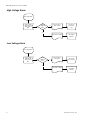
DX Demand (Dehumidification):
Cycles on compressors in stages 1 to 4 or 8 depending on Series and number of units connected
together with Co-Work as demand for dehumidification increases from 0 to 100%.
Demand for compressor:
• Compressor contactor receives signal from microprocessor. Positive Start timer (Pos. start delay)
starts and bypasses LP switch for cold winter start-up. When HP switch is closed the start circuit
is complete and the compressor starts.
• N/C auxiliary contact on compressor contactor opens and de-energizes receiver heaters. (Flooded
Condenser LAC)
• N/C auxiliary contact on compressor contactor opens and de-energizes crankcase heater.
• N/O auxiliary contact on compressor contactor starts remote condenser. (Air-cooled units only)
• Low-pressure switch remains closed after Pos. start time expires and compressor remains on.
Rapid Dehumidification Feature (Series 6 units only)
If there is less than 20 percent demand for cooling and a demand for dehumidification the Dehum.
Solenoid valve closes.
M52UMCT2014.DOC 2014
7
M52 Microprocessor User's Guide
The Dehum. Solenoid closes off refrigerant flow to part of the evaporator coil. This causes a
drop in suction pressure and a lower coil surface temperature over a portion of the coil. The
coil begins to remove more moisture as a result. The air is partially reheated, as the air through
the inactive part of the evaporator is unconditioned. This creates an overall drop in the sensible
heat ratio (Rapid Dehumidification)
During dehumidification demand, some sensible cooling takes place. Under very low load
conditions, the sensible cooling effect maybe greater than the combined offsetting effect of the
heat load plus the available reheat capacity, which may cause a drop in room temperature. If
temp continues to drop and is less than (setpoint MINUS (temp dead band DIVIDED by 2)
MINUS heating proportional band) the compressors will stop overriding the demand for
Dehum. The temperature must return to set point before another cycle of dehumidification
starts.
ie: Low limit cutout =[Set point – (temp deadband ÷2) – heating propband]
Compressor stops when:
•
Loss of demand
Compressor contactor opens
• Low pressure condition
Compressor stops when LP SW. opens. (Automatic reset) compressor contactor opens.
• Short cycling alarm
After three consecutive low-pressure alarms in 30 mins, compressor contactor opens.
Alarm must be acknowledged and cleared before Compressor will start.
• High pressure condition
Compressor stops when HP Switch opens. (Manual reset)
Compressor contactor opens. Compressor will not start until HP Switch is manually reset
and Alarm is acknowledged and cleared.
• Thermal protection opens (automatic reset)
Line voltage cut-outs on all compressors except Specter compressor where the compressor
module causes a Compressor Overload alarm and stops the compressor through the
microprocessor. Compressor module resets after 30 minutes.
• Low limit temperature
If return air temperature continues to drop and is less than (setpoint MINUS (temp dead
band DIVIDED by 2) MINUS heating proportional band) the compressors will stop
overriding the demand for Dehum.
Note: Anytime the compressor contactor opens the comp. elapse timer keeps compressor off
for 3 minutes (adjustable)
Dual Cooling Units:
Dual cooled units operate on DX as described above in DX Cooling Demand and DX
Dehumidification Demand. In DX mode the chilled water valve is closed. When a remote
signal contact input closes on both Chiller Ready Terminal 31 and 32 and Compressor Disable
Terminal 33 and 34 the compressors will stop and the unit will operate as described in Chilled
Water above.
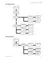
Free Cooling Units:
Free cooling units operate on DX as described above in DX Cooling Demand and DX
Dehumidification Demand when the glycol loop temperature is above 7.2°C, (45°F). The modulating
8
M52UMCT2014.DOC 2014
M52 Microprocessor User's Guide
glycol valve begins to open when the difference between the return air temperature (Temp 1) and the
(EGT) entering glycol temperature (temp 2) is greater than 3°C, (6°F). The unit will operate in Free
Cooling as long as the cooling demand remains in the 0-50% range. Once the cooling demand reaches
51-99% range the unit will operate with one circuit in Free Cooling and the opposite circuit in DX
Cooling. If the cooling demand reaches 100% then the unit will switch to DX cooling only.
When the glycol temperature drops below 7.2°C (45°F) the compressors will stop automatically. The
unit will operate in Free Cooling mode only at this time. The glycol temperature is monitored by the
unit using Temp 2 input. Temp 1 and Temp 2 can be viewed in the Test Mode section on page three.
If the Glycol Temperature drops below 0°C, (32°F) the unit will switch to DX cooling only as this low
of a Glycol fluid temperature would cause any condensation on the evaporator coil to freeze..
Note: The Status screen on the controller indicates free cooling is on when it displays 2/2 and off
when it displays 0/2 under the percentage demand next to the Free Cooling icon.
Reheat:
On demand for heat the demand signal ramps up and heater contactor closes at 100% demand, for one
stage or at 20% with SCR. SCR modulates from 20 to 100% output to match the demand signal. On
multi-stage heaters each stage will be energized at equal intervals as the demand increases from 0 to
100%.
Heater stops when:
Loss of demand
Loss of air flow
Heater high temp cut out
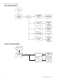
Humidifier:
When the “On/Off/Drain “ switch is in the “On” position, a demand for humidification causes the
humidifier contactor(s) to close in stages 1 to 4 or 8, (depending on Series and number of units
connected together with Co-Work), as demand for humidification increases from 0 to 100%.
After a short time delay, approximately 1 to 3 minutes, the fill valve will energize allowing water to
fill the boiler bottle. The fill valve closes when the humidifier reaches its FLA current or when the
water level reaches the high water level sensor. Water begins to boil after a few minutes. The
humidifier will continue to boil and fill to maintain the humidity setpoint. Periodically the humidifier
will initiate a flush cycle to maintain constant steam output and to flush some of the mineral content
from the boiler bottle.
When the boiler bottle reaches the end of its useful life it will activate a Boiler Dirty Alarm and will
shut off the humidifier. It is common for the Boiler Dirty Alarm to sound on an initial start-up as the
humidifier begins the process of concentrating the mineral content of the contained water.
To drain the humidifier you must cause a humidification demand and then switch the “On/Off/ Drain”
switch to Drain. You must set the switch back to “Off “when the bottle has completely drained.
Humidifier stops when:
“On/Off/Drain” switch is switched "Off"
M52UMCT2014.DOC 2014
9
M52 Microprocessor User's Guide
Loss of demand
Loss of air flow
Boiler Dirty Alarm intervention.
PID
The M52 microprocessor uses PID control logic to maintain the set point conditions. The following
parameters are adjustable so the controller can be fine-tuned to specific site conditions.
Dead band, temp. humid. dead band
Cool prop. band
Heating prop. band
Humidifying prop. band
Dehum. prop. band
Integral time temp
Integral time hum.
Internal Safety Controls
Fuses (60 Hz), circuit breakers (50 Hz) on all components
Fan overload relay (Vertical floor mount, VFM systems only)
Air proving switch (Vertical floor mount, VFM systems only)
Dirty filter switch (Vertical floor mount, VFM systems only)
High pressure refrigerant (manual reset)
Low pressure refrigerant
Internal thermal protection compressor and motor
High temp cut out for heater
Boiler dirty for humidifier
Compressor elapse timer
Crank case heaters
External Optional Safety Controls
Fire stat terminals 19 and 20
Smoke detector terminals 19 and 20
Liquid detector J51-01 02 and 03
On/Off Control
Local Mode:
When the controller is set to Local Mode, On/Off control of the unit is controlled by the keypad
Remote Mode:
When the controller is set to Remote, On/Off control is controlled by a remote signal through
terminals 15 and 16.
Timer Mode:
When the controller is set to Timer, On/Off control follows the time schedule programmed on the
controller. Unit can be set to be On, Off or Relax. Relax mode cause the microprocessor to control
using the RELAX deadbands which are programmable. In this mode the fan continues to operate.
Back up Capability
Standby Enable:
Each unit sends an output to start a back up unit in the event of an alarm condition as configured in the
Alarm Response menu. Terminals 11 and 12
Standby Start:
Each unit accepts an input signal to start regardless of its On/Off mode state at terminals 17 and 18
10
M52UMCT2014.DOC 2014
M52 Microprocessor User's Guide
Note: On/Off mode:
When operating in a Co-Work network all On/Off mode options are synchronized. Therefore, turning
off a unit, either by the touch screen when in Local, by the remote on/off at terminals 15 and 16 when
in Remote, or through the schedule when in Timer mode will turn off all units in that network.
To turn off an individual unit either as a stand-alone or in a Co-Work network see the Test Mode
section or simply open the disconnect switch.
M52UMCT2014.DOC 2014
11
M52 Microprocessor User's Guide
Powering Up / Powering Down
The first powering up must be performed by CLIMATEWORX authorized
personnel only. Failure to do so may damage the unit and void the warranty.
The main power switch (rotary disconnect) is located on the front of the unit. Series 6, 8 and 9
only.
Immediately after turning on the main power switch, the control system will perform the
following power up sequence:
1.
The control system will generate three short “beep” sound to alert power has been
applied and the unit is about to start.
2.
The control system will then perform a self-test and verify all stored setting and data are
within valid range.
3.
After the self-test, the control system will count down the programmed “Restart delay”
time and then put the system into normal operation.
To power down unit:
For units in Local Mode log into appropriate security level (refer to Log-in Security). An
On/Off toggle switch will appear on the bottom left corner of the display. Press “O” to power
down unit. Once fan stops, open disconnect.
For units in Timer or Remote Modes, log into security level number three, change On/Off mode
to “Local” (Settings tab, page 2). Follow above procedure to power down unit.
12
M52UMCT2014.DOC 2014
M52 Microprocessor User's Guide
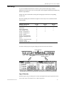
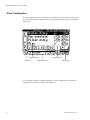
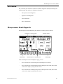
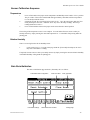
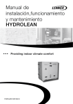
The Control Panel
The control panel is formed by a graphic LCD display and an overlay touch screen keypad. The
layout of the screen consists of three distinctive regions - the Banner line, the Active tab display
area and the Tab bar. The tabs are set-up like the tabs in a 3-ring binder. Each section contains
different information.
Banner line
The Banner line shows the system type and the current date and time. Date is in
DD/MM/YYYY format and time in 24-hour HH:mm format.
Active tab display area
Data and information are grouped into tabs for ease of retrieval. The Active tab display area
shows information corresponding to the current selected tab.
Tab bar
Tab bar shows the available tabs and allows user to switch tab display by pressing the
corresponding tab icon. There are 7 tabs in the Tab bar:
Operating Status Tab
Alarm Tab
Historical Event Tab
Timer On/Off Schedule Tab
Temperature and Humidity Graph Tab
Settings Tab
Testmode Tab
M52UMCT2014.DOC 2014
13
M52 Microprocessor User's Guide
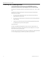
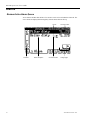
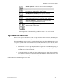
Operating Status
Network address
Unit fan on/off
icon
Main or return air
temperature
Main or return
air humidity Co-Work address icon
Alarm icon
On/Off mode icon
Process status display
Main Return Air Temperature & Humidity Readout
The main temperature & humidity readout shows the values of the return air being sensed by
the system. Temperature readout can be displayed in either °C or °F depending on the setting
“Temperature display”.
Process Status Display
This region shows the current operating status of the system by means of graphic icons and
analogue bar.
Heating
Cooling
Dehumidifying
Humidifying
Free
Cooling
rd
(3 ba r w hen a cti ve)
Network Address
This shows the Network address set in setting “Network address”. Every unit in the network
must be set to a unique address. This address relates to the RS485 serial communication buss.
14
M52UMCT2014.DOC 2014
M52 Microprocessor User's Guide
Alarm Icon
The alarm icon shows up if there is any active alarm in the system. You can review the details
of the alarm in the {Alarm} tab.
Unit fan On/Off Icon
The unit fan on/off icons show up when the unit fan is running. This icon changes from
continuously on to blinking when the unit is under fan purge shutdown.
On/Off Mode Icon
The On/Off mode icons keep you aware of the current On/Off mode selection. The On/Off
mode selection can be set in the “On/Off mode” setting under the {Setting} tab.
Local on/off control via control panel
Remote on/off control via switch input
Programmed timer schedule auto on/off
Standby start back-up start mode
M52UMCT2014.DOC 2014
15
M52 Microprocessor User's Guide
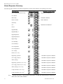
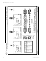
Co-Work™ Address Icon
This shows the Co-Work™ operation mode and network address.
Duty Master
(e.g. Address 1)
Standby Master
(e.g. Address 1)
Every master unit in the Co-Work™ network must have a unique address which can be set
through the DIP switches on the main board and I/O expansion board.
Co-Work Address
Main Board
I/O Expansion Board
ON
1
M1
2
M2
3
M3
4
M4
5
M5
6
M6
7
M7
8
M8
ON
D1
1 2
ON
3
4
1 2
ON
3
4
1 2
ON
3
4
1 2
ON
3
4
1 2
ON
3
4
1 2
ON
3
4
1 2
ON
3
4
1
3
4
1 2
ON
3
1 2
ON
3
1 2
ON
3
1 2
ON
3
1 2
ON
3
1 2
ON
3
1 2
ON
3
1
3
D2
D3
D4
D5
D6
2
D7
D8
2
Note: Above table is valid for Series 6, 7, 8 and 11 (Single Compressor Units) up to 8 units
Co-Work Address
Main Board
I/O Expansion Board
ON
1
ON
D1
M1
1
2
3
4
1 2
ON
3
1 2
ON
3
1 2
ON
3
1 2
ON
3
1 2
ON
3
1 2
ON
3
1 2
ON
3
1
3
D2
ON
2
M2
1
2
3
4
D3
D4
ON
3
M3
1
2
3
4
D5
D6
ON
4
M4
1
2
3
4
D7
D8
2
Note: Above table is valid for Series 9 (Dual Compressor Units) up to 4 units
16
M52UMCT2014.DOC 2014
M52 Microprocessor User's Guide
Security
To prevent unauthorized interference with the system operation and settings, the M52
Microprocessors have three levels of security that can be assigned to different personnel having
different responsibilities.
Settings can only be altered after entering the four-digit password for the corresponding
security level.
The factory default password and access right for each security level is summarized in the
following table:
Function / Description
Default password
Local on/off control
Alarm clear
Alarm configuration
Time schedule / clock
Setting - configuration 1
Setting - configuration 2
Setting - reading
Setting - control parameter
Testmode - Microprocessor
board
Testmode - digital I/O board
Testmode - sensor
Testmode - default value
Level 1
1024
Level 2
4321
Level 3
1234
To invoke security log-in or log-out, simply press the active tab on the Tab bar:
Press active tab
not logged-in
already logged-in
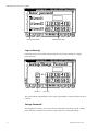
Log-in Security
On the first power-up, you can log-in to security by using the factory preset password “1024”,
“4321” and “1234” for security level 1, 2 and 3 respectively.
M52UMCT2014.DOC 2014
17
M52 Microprocessor User's Guide
Security level selector
Password enter keys
Log-out Security
Exiting the security can be achieved by pressing the Log-out key in the log-out / change
password screen.
Cancel key
Log-out key
The system will also automatically re-lock security approximately 1 minutes after the last key is
released.
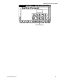
Change Password
After logging-in to security, you can press the active tab again to invoke the log-out / change
password screen. You have to key in the new password twice to confirm the change.
18
M52UMCT2014.DOC 2014
M52 Microprocessor User's Guide
Password enter keys
M52UMCT2014.DOC 2014
19
M52 Microprocessor User's Guide
Alarms
Review Active Alarm Queue
Active alarms and their date & time of occurrence can be reviewed under the alarm tab. The
active alarms are displayed chronologically with the latest alarm at the top.
Unit no.
Scroll bar
20
Alarm description
Occurrence date
Occurrence time
Change page
M52UMCT2014.DOC 2014
M52 Microprocessor User's Guide
Acknowledging Alarm
In case of an alarm condition occurrence and provided the alarm is enabled and configured for
audible warning, (See Alarm Configuration), a pop-up message will display on the screen like
the following:
Acknowledge alarm key
You are requested to press the alarm activated “tick” or “check” mark, [Alarm acknowledge]
alarm key in order to mute the audible warning and de-activate the common alarm output. The
alarm will not return again. Therefore it is imperative that you respond with the appropriate
action to the alarm. See the Fault Finding section.
Clear Alarm Message
Alarm message in the active alarm queue can only be cleared if both the following two
conditions are satisfied:
• The alarm condition has been rectified, which restores the safety switch to its normal
position and
• The message is confirmed to be cleared by pressing the [Alarm message clear] key.
Note: The [PC board Co-Work Address] identifies which PC board the alarm was registered by.
Alarm message clear key
PC board Co-Work Address
M52UMCT2014.DOC 2014
21
M52 Microprocessor User's Guide
Alarm Configuration
The alarm configuration screen is under the active alarm queue screen inside the {Alarm} tab.
You can switch to alarm configuration screen by pressing the [Change page] key in the alarm
queue screen.
Alarm description
Scroll bar
Configuration keys
Configuration icon
Change page
Every alarm has a number of configuration options. You can customize the way alarms are
reported and what automatic actions will be performed.
22
M52UMCT2014.DOC 2014
M52 Microprocessor User's Guide
Enable option key - alarm will only be monitored if this option
is selected.
Unit shutdown option key - if this option is selected, unit will
be automatically shutdown under alarm condition.
Standby enable option key - if this options is selected,
standby enable output will be activated under alarm condition.
Common alarm option key- if this options is selected,
common alarm output will be activated under alarm condition.
Event log option key - if this options is selected, the alarm
events will be logged in the historical event log.
Audible warning option keys- provides selection of three
different audible warning sound.
Alarm configuration will be automatically synchronized across the Co-Work™ network.
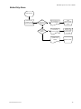
High Temperature Alarm note:
There is a new response outcome in the event of a high temperature alarm. The factory default response
is set to turn on the next available standby unit when back-up units are connected in a Co-Work network.
This means additional cooling capacity is automatically added to the space when a high temperature alarm
is registered regardless of the Alarm Configurations set for this alarm. However, certain sites may not be
able to handle this increase in air volume. Therefore, the factory can also enable the following features:
1
1.
SWAP ON1: In the event a high temperature alarm is registered on a standby unit (signifying a
hot spot in the room) the microprocessor will start this standby unit and stop the duty unit that is
sensing the lowest return air temperature.
2.
CW SWAP1: Disables the standby start feature on high temperature alarm in the event that the
unit is connected to ductwork or a raised floor that cannot handle the increased air volume when
all standby units are running in addition to the duty units.
Contact ClimateWorx when choosing the above options.
M52UMCT2014.DOC 2014
23
M52 Microprocessor User's Guide
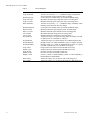
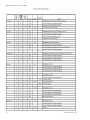
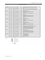
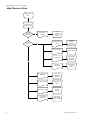
Alarm Response Summary
The following table summarizes the default configuration for all the alarms and their corresponding system action:
Alarm Message
Fan overload (DP float S11 only)
Default Configuration
Mandatory System Action
Immediate unit shutdown
Low airflow
Boiler dirty
Humidifier shutdown
Heater overheat
Heater shutdown
Filter dirty
Immediate unit shutdown 1
Fire
Flood
High humidity
High humidity 2
High temperature
High temperature 2
High voltage
Low Humidity
Low humidity 2
Low temperature
Low temperature 2
Low voltage
Fault 1 (Series 9 only)
Note:
24
High refrig. pressure 1
Immediate compressor shutdown
Low refrig. pressure 1
Immediate compressor shutdown
Short cycling 1
Immediate compressor shutdown
High refrig. pressure 2 (Series 9 only)
Immediate compressor shutdown
Low refrig. pressure 2 (Series 9 only)
Immediate compressor shutdown
Short cycling 2
Immediate compressor shutdown
(Series 9 only)
Comp.overload 1 (Series 9 only) 2
Immediate compressor shutdown
Comp.overload 2 (Series 9 only) 2
Immediate compressor shutdown
1
All units in the same Co-Work network will shut down. 2 On DX units fitted with Specter compressors
ZR90, ZR11, ZR12, ZR16 and ZR19
M52UMCT2014.DOC 2014
M52 Microprocessor User's Guide
Historical Event Log
For fault analysis, the system maintains the latest 50 historical events logged in the memory.
The logs are ranked chronologically with the latest event at the top.
Scroll bar Event type icon
Event description
Unit no.
Log date Log time
The following type of events will be logged:
Power failure / Power restore / Unit start / Unit stop
Alarm raised
Alarm acknowledged
Alarm cleared
M52UMCT2014.DOC 2014
25
M52 Microprocessor User's Guide
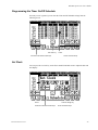
Timer On/Off Schedule
Review Timer On/Off Schedule
The weekly on/off program provides 4 changeover events per day and 7 days per week
automatic on/off/relax control for the system.
7 days schedule
4 changeover events per day
Each changeover event can be set to either “On”, “Off” or “Relax” which provides the
following responses:
uses “Dead band 1” setting for close control
when close control is not required,
uses “Relax deadband” setting to conserve energy while
room condition within acceptable limit
turn unit off
26
M52UMCT2014.DOC 2014
M52 Microprocessor User's Guide
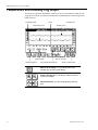
Programming the Timer On/Off Schedule
If security access is granted, you can alter the Timer On/Off Schedule settings from the
following screen:
Set clock key
Increment / Decrement value keys
Cursor
Cursor movement keys
Set Clock
You can press the set clock key on the Timer On/Off Schedule screen to adjust the date and
time display.
Cursor
Increment / Decrement value keys
M52UMCT2014.DOC 2014
Confirm change key
Cursor movement keys
27
M52 Microprocessor User's Guide
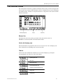
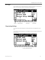
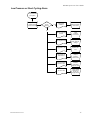
Temperature and Humidity Log Graph
The historical temperature and humidity variation can be reviewed under the Graph tab. The
log graph stores the latest 24-hour main temperature and humidity data. Data are logged in 15
minutes interval.
Temperature axis
Temperature curve
Guide humidity
Guide temperature
Humidity axis
Guide
Humidity curve
Zoom in / out keys
Curve display switching key
Guide movement keys
Switch curve display - to cycle temperature only,
humidity only or both curves display.
Zoom in & Zoom out - to enlarge or reduce the scale
of the curve display.
Guide movement - to move the guide along the time
axis.
28
M52UMCT2014.DOC 2014
M52 Microprocessor User's Guide
Settings
System settings can be reviewed and altered in the {Setting} tab. Settings are divided into three
groups. You can switch the display by pressing the [Change page] keys.
Scroll bar
Setting description
Setting value
Change page
Programming Settings
You can alter any keycode setting only if you have gained access to the appropriate security
level.
After gaining the programming right, you can change the settings by using the [Increment] and
[Decrement] keys.
Increment / Decrement value key
M52UMCT2014.DOC 2014
29
M52 Microprocessor User's Guide
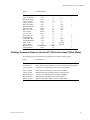
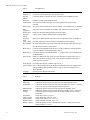
Settings Summary Version 473 (All units except Chilled Water)
The following tables summarize the settings in each page:
Page 1 :
Configuration 1
Description
No. of duty unit
Temp. setpoint
Temp. Hi limit
Temp. Low limit
Humid. setpoint
Humid. Hi limit
Humid. Lo limit
Range
1-8
15-30
15-37
10-30
30-80
50-90
20-50
Page 2 :
Configuration 2
Description
Software ver.
Network address
Baud rate
On/Off mode
Restart mode
Auto changeover
Restart delay
Warm-up period
Fan purge delay
Comp. elapse
Pos.start delay
Boiler dirty T.
Boiler limit T.
Sensor mode
Range
1-99
1200/9600
Local/Remote/Timer
Auto/Manual
0-9999
0-9999
0-9999
0-9999
0-250
0-9999
0-9999
15-1440
Local/Remote/DemoL
/Demo R/Disable
°C/°F
Unit/Site
English/Chinese
Temp. display
Sensor display
Language
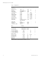
Page 3 :
Description
Main temp.
Temperature - 2
Main humidity
Humidity - 2
Voltage
Fan runtime
Comp.1 runtime (1-8)
Heater runtime (1-8)
Humid. Runtime (1-8)
Dehum. Runtime (1-8)
30
Default
1
22
30
15
50
70
30
Units
°C
°C
°C
%rh
%rh
%rh
Synchronization
Default
1
1200
Local
Auto
24
10
120
120
180
30
900
30
Local
Units
hours
seconds
seconds
seconds
seconds
seconds
seconds
minutes
-
Synchronization
°C
Unit
English
-
Default
0
0
0
0
0
Units
°C
°C
%rh
%rh
hours
hours
hours
hours
hours
Readings
Range
0-50.0
0-50.0
0-99.9
0-99.9
50-130
0-32000
0-32000
0-32000
0-32000
0-32000
Synchronization
M52UMCT2014.DOC 2014
M52 Microprocessor User's Guide
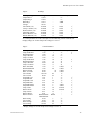
Page 4 :
Description
Temp. dead band
Relaxband Temp
Temp.2 Hi limit
Temp.2 Lo limit
Hum. dead band
Relaxband Humid
Hum.2 Hi limit
Hum. 2 Lo limit
Volt. Hi limit
Volt. Lo limit
Prop.band Cool
Prop.band Heat
Prop.band Humid
Prop.band Dehum
Temp. I-time
Humid. I-time
Humid. Control
Setback Humid.
Control Parameter
Range
0-10
0-20
15-37
0-30
0-30
0-50
50-90
20-50
102-120
80-98
1-10
1-10
2-10
2-10
1-30
1-30
Enable/Disable
30-80
Default
2
5
30
0
6
20
70
30
115
85
2
2
5
5
30
30
Enable
50
Units
°C
°C
°C
°C
%rh
%rh
%rh
%rh
%
%
°C
°C
%rh
%rh
seconds
seconds
-
Synchronization
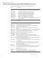
Settings Summary Glossary Version 473 (All units except Chilled Water)
The following provides a definition of the parameters used in the Settings section:
Page 1:
Configuration 1
Parameter
Definition
No Duty Units
Temp. setpoint
Temp. Hi limit
Temp. Lo limit
Humid. setpoint
Humid. Hi limit
Humid. Lo limit
Units required to run together in a Co-Work network to satisfy the load.
Controls space temperature base on return air temperature.
Maximum return temperature before activating alarm 1
Minimum return air temperature before activating alarm 1
Controls space humidity based on return air humidity
Maximum return humidity before activating alarm 1
Minimum return air humidity before activating alarm 1
M52UMCT2014.DOC 2014
31
M52 Microprocessor User's Guide
Page 2:
Configuration 2
Parameter
Definition
Software ver.
Network
address
Baud rate
On/Off mode
Version of software operating on the microprocessor
Controller address to identify the unit in a SatchNet network/BMS Network
Restart mode
Auto
changeover
Restart delay
Warm-up
period
Fan purge
delay
Comp. elapse
Pos.start delay
SatchNet network communication speed
Sets unit to turn “ON” and “OFF” by local keypad, remote signal or timer
schedule.
In a power failure this allows the unit to turn back “ON” automatically or manually
Time interval after which duty and standby unit switch in a Co-Work network
Delays the unit from starting until the time limit expires.
Allows sensor reading to stabilize before tripping alarms
Runs fan for minimum time to dissipate heat in components before fan shutdown.
Prevents compressors from restarting for minimum time after stopping
By passes refrigerant low-pressure switch and alarm during compressor start-up to
prevent nuisance alarms in cold weather. 1
Boiler dirty T. Connected to the humidifier high water level sensor and delays boiler dirty alarm
to prevent nuisance alarms on humidifier start-up. 1
Boiler limit T. Not used with steam electrode humidifier. Activates a drain cycle to flush the pan
on IR humidifiers.
Sensor mode
Enables or disables the units return air sensor from the averaging feature in a CoWork network during standby periods. Also used for M52 Demo controllers or
remote supervisory panels.
Temp. display Sets temperature display on Status page to °F or °C
Sensor Display In a Co-Work network choose to display the individual unit sensor readings or the
average readings (SITE readings are the average of all sensor readings in a CoWork network)
Language
Choose between English and Chinese
Page 3:
Readings
Parameter
Definition
Main temp.
Temperature - 2
Calibration function used to fine tune the return air temperature sensor.2
Calibration function used to fine-tune the spare temperature sensor. 2 (used only
in free cool units for monitoring glycol loop temperature)
Calibration function used to fine-tune the return air humidity sensor. 2
Calibration function used to fine-tune the spare humidity sensor. 2 (not used)
Calibration function used to fine tune the voltage reading from the control
transformer.2
Totals fan run time, 1 to 4 or 8
Totals compressor run time, 1 to 8
Totals heater run time, 1 to 4, 8 or 12
Totals humidifier run time, 1 to 4 or 8
Totals full cooling run time. Dehumidifier run time = compressor run time –
Dehum runtime, 1 to 4 or 8
Main humidity
Humidity - 2
Voltage
Fan runtime
Comp. runtime
Heater runtime
Humid. runtime
Dehum. runtime
32
M52UMCT2014.DOC 2014
M52 Microprocessor User's Guide
Page 4:
Control Parameter
Parameter
Definition
Temp. dead band
Tolerance for return air, + or – ½ deadband. Range of temperature where
temperature control operation does not change
Used in the timer schedule allows an alternate deadband setting
Maximum allowable spare temperature before activating alarm 1
Minimum allowable spare temperature before activating alarm 1
Tolerance for return air, + or – ½ deadband. Range of humidity where
humidity control operation does not changes
Used in the timer schedule allows an alternate deadband setting
Maximum allowable spare humidity before activating alarm 1
Minimum allowable spare humidity before activating alarm 1
Maximum allowable voltage before activating alarm 1
Minimum allowable voltage before activating alarm 1
Temperature range over which all cooling stages are equally activated or
chilled water valve modulates to full open.
Temperature range over which all heater are modulated (Staged AP)
Humidity range over which all humidifier stages are equally activated.
Humidity range over which all dehumidification stages are equally activated
or chilled water valve modulates to full open.
Integral action time constant used in the PID control loop
Integral action time constant used in the PID control loop
Choose to enable or disable humidity control.
Series 9 only, allows an alternate humidity setpoint to be selected and
controlled by a digital input signal by others
Relaxband Temp
Temp.2 Hi limit
Temp.2 Lo limit
Hum. dead band
Relaxband Humid
Hum.2 Hi limit
Hum. 2 Lo limit
Volt. Hi limit
Volt. Lo limit
Prop.band Cool
Prop.band Heat
Prop.band humid
Prop.band Dehum
Temp. I-time
Humid. I-time
Humid. Control
Setback Humid.
Notes: 1 Alarms activate only if they are enabled in the Alarm Configuration section. 2 These parameters
are to be used only when performing a calibration check of the unit sensors. Do not adjust, as
this will cause the unit to malfunction.
Settings Summary Version 491B2 (Chilled Water units only)
The following tables summarize the settings in each page:
Page 1 :
Description
No. of duty unit
Temp. setpoint1
Temp. Hi limit
Temp. Low limit
Temp. setpoint*
Temp. Hi limit*
Temp. Low limit*
Humid. setpoint
Humid. Hi limit
Humid. Lo limit
No. of standby
Configuration 1
Range
1-8
12-30
12-37
5-30
53-86
53-99
41-86
30-80
50-90
20-50
1-7
Default
1
22
30
15
72
86
59
50
70
30
0
Units
°C
°C
°C
°F
°F
°F
% RH
% RH
% RH
-
Synchronization
1) Set point adjustment range of 12 – 30˚C
* Display changes to °F when Temp Units on Page 2 is set to °F
M52UMCT2014.DOC 2014
33
M52 Microprocessor User's Guide
Page 2 : Configuration 2
Description
Software ver.
Network address
Baud rate
On/Off mode
Restart mode
Auto changeover
Restart delay
Warm-up period
Fan purge delay
Comp. elapse
Pos.start delay
Humid. Ser. delay
IR auto flush
Sensor mode
Temp. units
Sensor display
Language
Common Alr. Mode
Page 3 :
Description
C. water circuit 1
C. water circuit 2
C. water 1 temperature
C. water 2 temperature
C. water 1 temperature*
C. water 2 temperature*
Primary circuit
Changeover delay
C.W. temp. limit
C.W. temp. limit *
Normal fan
Backup fan
Range
Default Units
1-999
001
1200 – 19.2K
1200
bps
Local/Remote/Timer
Local
Auto/Manual
Auto
0-9999
24
hours
0-9999
10
seconds
0-9999
120
seconds
0-9999
120
seconds
0-250
180
seconds
0-9999
180
seconds
0-9999
900
seconds
0-9999
0
minutes
Local/Remote/DemoL Local
/Demo R/Disable
°C/°F
°C
Unit/Site
Unit
English/Chinese
English
Site/Unit
Site
-
Synchronization
Readings
Range
Default Units
Enable/Disable Disable
Enable/Disable Disable
0-45
°C
°C
0-45
°F
32-113
°F
32-113
1-2
1
0-9999s
60
seconds
5-15
10
°C
41-59
50
°F
10-100
80
%
10-100
100
%
Synchronization
* Display changes to °F when Temp Units on Page 2 is set to °F
34
M52UMCT2014.DOC 2014
M52 Microprocessor User's Guide
Page 4 :
Description
Temperature 1A
Temperature 2
Humidity 1A
Humidity 2
Voltage
Fan runtime (1-8)
Comp.1 runtime (1-8)
Heater runtime (1-8)
SCR Heat. runtime
Humid. Runtime (1-8)
Dehum. Runtime (1-8)
Readings
Range
0-50.0
0-50.0
0-99.9
0-99.9
50-130
0-32000
0-32000
0-32000
0-32000
0-32000
0-32000
Default
0
0
0
0
0
0
Units
°C
°C
%RH
%RH
hours
hours
hours
hours
hours
hours
Synchronization
A) These parameters are used as the inputs for all conditioning control within the unit.
Display changes to °F when Temp Units on Page 2 is set to °F
Page 5 :
Description
Temp. dead band
Relaxband Temp
Temp.2 Hi limit
Temp.2 Lo limit
Temp. dead band*
Relaxband Temp*
Temp.2 Hi limit*
Temp.2 Lo limit*
Hum. dead band
Relaxband Humid
Hum.2 Hi limit
Hum. 2 Lo limit
Volt. Hi limit
Volt. Lo limit
Prop.band Cool
Prop.band Heat
Prop.band Cool*
Prop.band Heat*
Prop.band Humid
Prop.band Dehum
Temp. I-time
Humid. I-time
Temp. D-time
Humid. D-time
Humid. Control
Dual-cooling
Free-cooling
Dual-cooling*
Free-cooling*
Control Parameter
Range
0-10
0-20
15-37
0-30
0-18
0-36
54-99
0-30
0-30
0-50
50-90
20-50
102-120
80-98
1-10
1-10
2-18
2-18
2-10
2-10
1-30
1-30
0-61
0-94
Enable/Disable/
Humid/Dehum
0-130
0-130
32-266
32-266
Default
1
5
30
0
1.8
9
54
0
6
20
70
30
115
85
1
1
3.6
3.6
5
5
30
30
15
15
Enable
Units
°C
°C
°C
°C
°F
°F
°F
°F
% RH
% RH
% RH
% RH
%
%
°C
°C
°F
°F
% RH
% RH
seconds
seconds
-
3
7.2
5.4
45
°C
°C
°F
°F
Synchronization
* Display changes to °F when Temp Units on Page 2 is set to °F
M52UMCT2014.DOC 2014
35
M52 Microprocessor User's Guide
Settings Summary Glossary Version 491B2 (Chilled Water units only)
The following provides a definition of the parameters used in the Settings section:
Page 1:
Parameter
No Duty Units
Temp. setpoint
Temp. Hi limit
Temp. Lo limit
Humid. setpoint
Humid. Hi limit
Humid. Lo limit
No of Standby
Page 2:
Configuration 1
Definition
Units required to run together in a Co-Work network to satisfy the load.
Controls space temperature base on return air temperature.
Maximum return temperature before activating alarm 1
Minimum return air temperature before activating alarm 1
Controls space humidity based on return air humidity
Maximum return humidity before activating alarm 1
Minimum return air humidity before activating alarm 1
Number of standby units that will start in a high temperature alarm when in
a Co-Work network
Configuration 2
Parameter
Software ver.
Network address
Baud rate
On/Off mode
Definition
Version of software operating on the microprocessor
Controller address to identify the unit in a SatchNet network/BMS Network
SatchNet network communication speed
Sets unit to turn “ON” and “OFF” by local keypad, remote signal or timer
schedule.
Restart mode
In a power failure this allows the unit to turn back “ON” automatically or manually
Auto changeover Time interval after which duty and standby unit switch in a Co-Work network
Restart delay
Delays the unit from starting until the time limit expires.
Warm-up period Allows sensor reading to stabilize before tripping alarms
Fan purge delay Must be set to “0” for machine to run.
Comp. elapse
Prevents compressors from restarting for minimum time after stopping
Pos.start delay
By passes refrigerant low-pressure switch and alarm during compressor start-up to
prevent nuisance alarms in cold weather. 1
Humid. Ser. delay Connected to the humidifier high water level sensor and delays boiler dirty alarm
to prevent nuisance alarms on humidifier start-up. 1
IR auto flush
Not used with steam electrode humidifier. Activates a drain cycle to flush the pan
on IR humidifiers.
Sensor mode
Enables or disables the units return air sensor from the averaging feature in a CoWork network during standby periods. Also used for M52 Demo controllers or
remote supervisory panels.
Temp. unit
Sets ALL temperature display units to °F or °C
Sensor Display
In a Co-Work network choose to display the individual unit sensor readings or the
average readings (SITE readings are the average of all sensor readings in a CoWork network)
Language
Choose between English and Chinese
Common Alr.
‘Unit’ releases synchronization feature of the common alarm to work
Mode
independently in a Co-Work network. ‘Site’ maintains synchronization
36
M52UMCT2014.DOC 2014
M52 Microprocessor User's Guide
Page 3
Readings
Parameter
C. water circuit 1
C. water circuit 2
C. water 1 temperature
C. water 2 temperature
C. water 1 temperature*
C. water 2 temperature*
Primary circuit
Definition
Flow status of CW loop per BMS sensors
Flow status of alternate CW loop per BMS sensors
Temperature of alternate CW loop per BMS sensors °C
Temperature of alternate CW loop per BMS sensors °C
Temperature of alternate CW loop per BMS sensors °F
Temperature of alternate CW loop per BMS sensors °F
Sets the circuit number for use as primary cooling source
Provides minimum time delay during which both primary and secondary
CW circuits are functioning
Temperature when primary to secondary CW source takes place °C
Temperature when primary to secondary CW source takes place °F
Sets the fan speed when no cooling/heating or dehum demand is present.
Sets fan speed under alarm condition
Changeover delay
C.W. temp. limit
C.W. temp. limit *
Normal fan
Backup fan
Page 4:
Parameter
Temperature 1
Temperature 2
Humidity 1
Humidity 2
Voltage
Fan runtime
Comp. runtime
Heater runtime
SCR Heat runtime
Humid. runtime
Dehum. runtime
Readings
Definition
Calibration function used to fine tune the unit control temperature sensor.2
Calibration function used to fine-tune the spare temperature sensor. 2 (used only
in free cool units for monitoring glycol loop temperature)
Calibration function used to fine-tune the return air humidity sensor. 2
Calibration function used to fine-tune the spare humidity sensor. 2 (not used)
Calibration function used to fine tune the voltage reading from the control
transformer.2
Totals fan run time, 1 to 4 or 8
Totals compressor run time, 1 to 8
Totals heater run time, 1 to 4, 8 or 12
Totals SCR heater run time, 1 to 4 or 8
Totals humidifier run time, 1 to 4 or 8
Totals full cooling run time. Dehumidifier run time = compressor run time –
Dehum runtime, 1 to 4 or 8
2
These parameters are to be used only when performing a calibration check of the unit sensors. Do
not adjust, as this will cause the unit to malfunction. Sensor must be recalibrated when changing from
°C to °F.
M52UMCT2014.DOC 2014
37
M52 Microprocessor User's Guide
Page 5:
Parameter
Temp. dead band
Relaxband Temp
Temp.2 Hi limit
Temp.2 Lo limit
Hum. dead band
Relaxband Humid
Hum.2 Hi limit
Hum. 2 Lo limit
Volt. Hi limit
Volt. Lo limit
Prop.band Cool
Prop.band Heat
Prop.band humid
Prop.band Dehum
Temp. I-time
Humid. I-time
Temp. D-time
Humid. D-time
Humid. Control
Dual-cooling
Free-cooling
38
Control Parameter
Definition
Tolerance for return air, + or – ½ deadband. Range of temperature
where temperature control operation does not change
Used in the timer schedule allows an alternate deadband setting
Maximum allowable spare temperature before activating alarm 1
Minimum allowable spare temperature before activating alarm 1
Tolerance for return air, + or – ½ deadband. Range of humidity where
humidity control operation does not changes
Used in the timer schedule allows an alternate deadband setting
Maximum allowable spare humidity before activating alarm 1
Minimum allowable spare humidity before activating alarm 1
Maximum allowable voltage before activating alarm 1
Minimum allowable voltage before activating alarm 1
Temperature range over which all cooling stages are equally activated
or chilled water valve modulates to full open.
Temperature range over which all heater are modulated (Staged AP)
Humidity range over which all humidifier stages are equally activated.
Humidity range over which all dehumidification stages are equally
activated or chilled water valve modulates to full open.
Integral action time constant used in the PID control loop
Integral action time constant used in the PID control loop
Derivative function used in PID control loop
Derivative function used in PID control loop
Choose to enable or disable humidity control or control Humidity or
Dehumidification independently.
Adjusts the change over set point for CW to DX change-over
Adjusts the change over set point for Economizer to DX change-over
M52UMCT2014.DOC 2014
M52 Microprocessor User's Guide
Test Mode
The {Testmode} tab contains an assortment of utilities designed to simplify field testing and
troubleshooting. The utilities are divided into four pages:
-
Microprocessor board diagnostic
-
Digital I/O board diagnostic
-
Sensor calibration
-
Data re-initialization
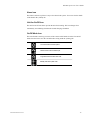
Microprocessor Board Diagnostic
The Microprocessor board diagnostic page under the {Testmode} tab is as follows:
Selected I/O Switched inputs
State selector
Switched outputs
Analogue outputs
Description line
Change page
Under the Microprocessor board diagnostic page, you can:
M52UMCT2014.DOC 2014
-
Review the status of the switched inputs on the Microprocessor board.
-
Review the status of the switched outputs on the Microprocessor board, and override
control of the outputs by using the state selector.
-
Review the status of the analogue outputs on the Microprocessor board, and override
control of the outputs by using the state selector.
39
M52 Microprocessor User's Guide
In the Microprocessor board diagnostic page, each input or output on the Microprocessor board
are represented by a symbol on the display. The representation of each graphic symbol is listed
in the following diagram:
Switched input / output opened
Switched output opened under override control
Switched input / output closed
Switched output closed under override control
Analogue output in percentage
Analogue output in percentage under override control
By "touching" the corresponding symbol, you can review the description of an input or output
on the description line.
40
M52UMCT2014.DOC 2014
M52 Microprocessor User's Guide
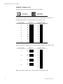
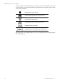
Digital I/O Board Diagnostic
The digital I/O board diagnostic page under the {Testmode} tab is as follows:
Selected slave board
State selector
Selected I/O
Available slave boards
Description line
Switched inputs
Switched outputs Change page
Under the digital I/O board diagnostic page, you can:
-
Select any of the linked digital I/O board to review.
-
Review the status of the switched inputs on the selected digital I/O board.
-
Review the status of the switched outputs on the selected digital I/O board, and override
control of the outputs by using the state selector.
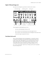
Test Mode Unit on/off
There is increased functionality on the I/O board diagnostics. It is possible to turn units
off from this section regardless of the On/Off mode setting by pressing the Card icon for
the unit you want to stop. When logged on to a level 1 password you will see the unit #
appear at the bottom of the screen that corresponds to the I/O card(s) selected. A state
selector appears and you can turn off the unit by selecting off. When the over-ride is
selected the I/O card will appear with square brackets around it indicating it is in override. To select a specific input or output for any card simply press the input or output light
bulb after selecting the card.
M52UMCT2014.DOC 2014
41
M52 Microprocessor User's Guide
Card icon
State selector
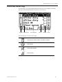
Sensor Calibration
The sensor calibration page under the {Testmode} tab is as follows:
Temperature input readings
Set 0°C
Humidity input readings
Supply voltage percentage
Load default value
Change page
Under the sensor calibration page, you can:
42
-
Review the current temperature inputs, adjust the 0°C reference and restore temperature
input offsets to default value.
-
Review the current humidity inputs and restore humidity input offsets to default value.
-
Review the supply voltage percentage.
M52UMCT2014.DOC 2014
M52 Microprocessor User's Guide
Sensor Calibration Sequence
Temperature
1.
2.
3.
Power off unit and set the jumper on the temperature and humidity sensor board to “Zero” position.
The pin 1 and 2 of the sensor board should read approximately 1000 ohms which corresponds to
0°C for the Hycal PT100 sensor.
Switch unit on and after one minute login security level 1. Go to the sensor page under the [Test
mode] tab and press the “Def.” And then “Set 0” key next to the temp1 reading. The Temp1
reading should now read 0° C
Power off the machine and reset the jumper on the sensor board to normal position.
The zeroing of the temperature sensor is now complete. You can further fine tune sensor to what you
actually measure by simply entering the measured temperature in ° C in the Main Temp setting under the
[Setting] tab.
Relative Humidity
There is no zeroing function for the humidity sensor.
1.
Login security level 1. Go to the sensor page under the [Test mode] tab and press the “Def.”
Key next to the Humid. 1 reading.
If required, fine tune sensor to what you actually measure by simply entering the measured relative humidity
in the Main Humidity setting under the [Setting] tab.
Data Re-initialization
The data re-initialization page under the {Testmode} tab is as follows:
Load default alarm configuration
Load default settings
M52UMCT2014.DOC 2014
Clear event data
Load default timer schedule
Clear graph data
Change page
43
M52 Microprocessor User's Guide
Under this page, you can:
1
44
-
Set alarm configurations to default configurations (See Alarm Response Summary)1.
-
Set timer on/off schedule to default configurations (See Timer On/Off Schedule).
-
Set system configuration and control settings to default configurations (See Setting
Summary)
-
Clear log data in historical event log.
-
Clear log data in temperature and humidity log graph.
Not advisable for chilled water units, Series 7 and 11 and units with options.
M52UMCT2014.DOC 2014
M52 Microprocessor User's Guide
Co-Work™
Co-Work™ is a six function networking feature that is built into every M52 controller.
Through the use of a six wire telephone cable you can link up to 8 compressor circuits on one
local area network. What this does is it makes all units in the network operate as one system
which improves the system performance, reliability and manageability.
Refer to page 59 for the wiring details.
Co-Work™ performs the following six functions:
Two Levels of Duty Sharing.
The first level maintains the required number of duty units in the network and automatically
sequences duty and redundant units on to even out run time. This function is time based and is
factory set for 24hrs. This value is adjustable.
The second level of duty sharing automatically initiates lead/lag sequence of the components
among the duty units to equalize run time.
Data Synchronization.
Unit operation data such as set points, time schedule, alarm status (see Setting Summary page
for list of synchronized data) is synchronized among units under the same Co-Work™ network.
Sequential Load Activation.
Co-Work™ coordinates the activation and deactivation of components in a unit and within a
group of units to minimize in-rush current.
Control Redundancy
Co-Work™ allows multiple master units to coexist on the same network. In case any master
requires service the remaining units will automatically take over control of the whole system.
In the event of a controller failure control will be transferred automatically to the other masters
minimizing loss of system control and down time.
Expansion of Control Steps
Co-Work™ improves the system performance by utilizing the limited number of control steps
in individual units and converts them to a maximum of 8 steps. This provides more precise
control and limits on/off cycles by matching capacity to load.
M52UMCT2014.DOC 2014
45
M52 Microprocessor User's Guide
Control Value Averaging
Co-Work™ exchanges sensor reading of temperature and humidity of network units and
operates from the average reading. This prevents units from fighting each other when multiple
units control one space.
Settings Menu, Sensor mode:
Additional flexibility in configuring a ‘n+1’ Co-Work network has been added. In certain cases
it could be desirable to ignore the sensor data from standby units. Therefore, the client may now
select to ignore or include sensor data from standby units. In the factory default setting, the
M52 will ignore sensor data from a standby unit in the calculation to determine the average
return air temperature and humidity in the controlled space. To include sensor data for standby
units, open page 2 of the Settings section and review the Sensor mode entry. To include the
sensor data of a standby unit in calculating the average return air temperature and humidity for
a space, select REMOTE option instead of LOCAL.
Setting up the Co-Work™ network:
This step must be performed first when setting up a Co-Work™ network with software
version 473 only. Go to the M52 controller on each unit to be placed in the Co-Work™
network and perform these steps.
Go to the settings screen, press settings tab to get the password request. Then press top
right hand corner of screen (you will not see anything happen). Enter in pass word 9911
then scroll over to page 5 of settings. You will see the option under High Temperature
Alarm to select for “SWAP ON”, “CW SWAP” and “TURN ON”. Select “TURN ON”
option unless a different response is required. See definitions on page 23.
Follow the field wiring diagram as shown on page 59
Power off each unit as detailed in section Powering On/Powering Down. Turn off power at the
unit mounted disconnect and open control panel door. Make your Co-Work™ wiring
terminations. Set the dip switch setting on each microprocessor main board and each
corresponding I/O expansion board as shown on page 16
Notice that dual compressor, Series 9 units have two I/O expansion boards.
Close control panel door and restore disconnect switch to on position. Logon to one unit in the
network and start the unit (see page 12)
The setting of these switches will create individual addresses for each unit. The address will be
displayed in the top right corner of the display (see page 14 & 16) Note the Network address
located in the top left corner of the screen refers to the RS485 communication network
SatchNet and is ClimateWorx’s control and monitoring software system. Consult your local
representative or the factory for details.
46
M52UMCT2014.DOC 2014
M52 Microprocessor User's Guide
Decide how many units are required to maintain the room load. This is the number of duty
units. Log on to any unit in the network using the Level 1 password. Select the Setting page.
Enter the number of duty units on page one of the settings tab.
Log off of the system (page 12)
The Co-Work network is now set up. Each unit has a unique address that identifies each
printed circuit board in the network. See page 14 & 16 for the PC board address code.
Notes:
Only one operator can use the key pad at a time. Once you logon to the network that unit
becomes the master. All other units will be locked and the keypads will display Master Lock if
you attempt to use them.
When an alarm condition is detected the alarm is broadcast to all units in the network. The
alarm can be acknowledged at any unit in the network.
When reviewing alarm in the Alarm tab or in the Historical Event log you must pay attention to
the PC board address to properly identify which unit in the network is alarming. This is the two
digit address that appears to the left of the event occurrence time in the Historical Event tab and
the Alarm tab. Events such as Unit on/off and Power Failure/Restore are shown for the
individual unit being poled.
You can program the network to display the temperature and humidity of the site (average of all
readings) or the individual temperature and humidity of the unit under the Settings tab. Refer to
the Setting section
Alarm Settings, Responses chart:
M52UMCT2014.DOC 2014
47
M52 Microprocessor User's Guide
48
M52UMCT2014.DOC 2014
M52 Microprocessor User's Guide
M52UMCT2014.DOC 2014
49
M52 Microprocessor User's Guide
Fault Finding
In some cases, determining the cause of a fault requires a fair amount of technical knowledge
and skill. The following fault finding charts are given as a guide for the service personnel to
locate the common faults which may be encountered in the unit.
High Temperature Alarm
High temperature
alarm
Main temperature
higher than "Temp.
Hi Limit" setting
Main
temperature too
high ?
no
Wrong setting in
"Temp. Hi Limit"
Set "Temp. Hi
Limit" 3-5°C
higher than
"Temp. setpoint"
Abnormal site
condition
Check opened
doors/windows
or abnormal site
condition
Inoperative cooling
system
Check cooling
system
operation
Wrong setting in
"Temp. Lo Limit"
Set "Temp. Lo
Limit" 3-5°C
lower than
"Temp. setpoint"
Abnormal site
condition
Check opened
doors/windows
or abnormal site
condition
Inoperative heating
system
Check heating
system
operation
yes
Low Temperature Alarm
Low temperature
alarm
Main temperature
Lower than "Temp.
Lo Limit" setting
Main
temperature too
low ?
no
yes
50
M52UMCT2014.DOC 2014
M52 Microprocessor User's Guide
High Humidity Alarm
High humidity
alarm
Main humidity
higher than
"Humid. Hi Limit"
setting
Main
humidity
too high ?
no
Wrong setting in
"Humid. Hi Limit"
Set "Humid. Hi
Limit" 5-10%rh
higher than
"Humid.
setpoint"
yes
Abnormal site
condition
Check opened
doors/windows
or abnormal site
condition
Inoperative
dehumidifying system
Check
dehumidifying
system
operation
Low Humidity Alarm
Low humidity
alarm
Main humidity
lower than "Humid.
Lo Limit" setting
Main
humidity
too low ?
no
Wrong setting in
"Humid. Lo Limit"
Set "Humid. Lo
Limit" 5-10%rh
lower than
"Humid.
Setpoint"
yes
M52UMCT2014.DOC 2014
Abnormal site
condition
Check opened
doors/windows
or abnormal site
condition
Inoperative
humidifying system
Check
humidifying
system
operation
51
M52 Microprocessor User's Guide
High Voltage Alarm
High voltage alarm
Supply voltage
higher than the
setting "Volt. Hi
limit"
Supply
voltage too
high ?
no
Wrong setting in
"Volt. Hi limit"
Set "Volt. Hi
limit" to 105115%
Poor power condition
Add voltage
stabilizer
yes
Low Voltage Alarm
Low voltage alarm
Supply voltage
lower than the
setting "Volt. lo
limit"
Supply
voltage too
low ?
no
Wrong setting in
"Volt. lo limit"
Set "Volt. lo
limit" to 85-95%
yes
Poor power condition
52
Add voltage
stabilizer
M52UMCT2014.DOC 2014
M52 Microprocessor User's Guide
Low Airflow Alarm
Low airflow alarm
Airflow differential
pressure switch
intervention
No air flow ?
no
Open panles in air
compartment
Close all panels
in the air
handling
compartment
Blocked air path
Clear
obstruction in air
path
yes
Fan
motor running ?
no
yes
Broken belts
Replace
defective belts
Overcurrent protective
device tripped
Check control
circuit
Defective fan motor
Check fan motor
Filter Dirty Alarm
Filter dirty alarm
Filter differential
pressure switch
intervention
Clogged
air filters ?
yes
Filter dirty
Replace air
filters
no
Wrong differential
pressure switch
calibration
Differential pressure
switch malfunction
M52UMCT2014.DOC 2014
Re-calibrate the
differential
pressure switch
Check bended
tubing and
differential
pressure switch
operation
53
M52 Microprocessor User's Guide
Fan Overload Alarm
Heater Overheat Alarm
Heater overheat
alarm
Safety overheat
thermostat
intervention
Dirty air filter
Too low airflow
54
Replace filter
and re-calibrate
the filter
differential
pressure switch
Check possible
obstructions in
air path
M52UMCT2014.DOC 2014
M52 Microprocessor User's Guide
Boiler Dirty Alarm
Boiler dirty alarm
Electrode boiler
humidifier control
board intervention
Water
level at top of the
cylinder ?
no
Water forning at top of
the cylinder due to
over concentration
Check
inoperative drain
valve or blocked
strainer
yes
Low concentration of
current carrying
minerals in cylinder
Dissolve half a
teaspoon of salt
in a cup of water
and fill into the
new cylinder
yes
Initial
startup with a new
cylinder ?
no
Cylinder is fully
calcified
M52UMCT2014.DOC 2014
Replace cylinder
55
M52 Microprocessor User's Guide
High Pressure Alarm
High pressure
alarm
Compressor high
pressure cutout
switch intervention
Too high
discharge
pressure ?
no
Wrong high pressure
cutout switch
calibration
Re-calibration
the high
pressure cutout
switch
yes
Air cooled
system ?
yes
Condenser fans not
running
Dirty condenser
Check
condenser
control circuit
and indoor unit
interlock wirings
Clean condenser
Too low airflow
Clear air intake
and discharge
obstructions
Too high air
temperature
Check possible
air short
circuiting
no
Water regulating valve
malfunction
Check water
regulating valve
operation
No condensing water
Check hydraulic
circuit
Dirty heat exchanger
Clean heat
exchanger
Too low water flow or
too high water
temperature
56
Check design
data and reset to
design condition
M52UMCT2014.DOC 2014
M52 Microprocessor User's Guide
Low Pressure or Short Cycling Alarm
Low pressure/short
cycling alarm
Compressor low
pressure cutout
switch intervention
Too low
suction
pressure ?
no
Wrong low pressure
cutout switch
calibration
Re-calibration
the low pressure
cutout switch
yes
Too low condensing
pressure
Check
condenser
control circuit
Low refrigerant charge
Check possible
leak, repair and
recharge
Clogged filter - drier
Replace filter drier
Failure liquid line
solenoid valve
Replace
defective
solenoid valve
Failure thermostatic
expansion valve
Replace
defective
thermostatic
expansion valve
Too low air flow
M52UMCT2014.DOC 2014
Check possible
obstructions in
air path and
clogged air filter
57
M52 Microprocessor User's Guide
Appendix A: Electrical Schematic Diagrams
58
Drawing Title
Drawing no.
Page No.
Electrical Schematic - IIC Interconnection Link
M52ES01E
59
Electrical Schematic - RS485 Serial Communication Link
M52ES02E
60
M52UMCT2014.DOC 2014
M52 Microprocessor User's Guide
M52UMCT2014.DOC 2014
59
60
1
U1
1
J13
1
J12
1
J11
R(-)
Grd
T/R(+)
T/R(-)
Not used
Not used
Not used
1
2
3
4
5
6
Not used
T(+)
T(-)
Grd
R(+)
Half duplex
M52ES02E
1
J01
BL1
Full duplex
J21 and J22 (RS485)
J14
J51
U3
JP1 JP2 JP11
U5
U14
J21 J22 J31 J32 J02
PIN No.
1
M52 - M V4
SW1
1 2 3 4
ON
LCD1
KB1
VR1
CANATAL
1
1
U5
U3
1
J13
1 J12 1 J11
J01
1
BL1
1
U3
J14
1 J51
JP1 JP2 JP11
U5
Half duplex
Full duplex
M52 - M V4
SW1
1 2 3 4
ON
LCD1
KB1
VR1
U1
1
J13
U14
1 J12 1 J11
J01
1
BL1
J21 J22 J31 J32 J02
6
5
4
3
2
1
6
5
4
3
2
1
To Host Systems'
RS485 Port
Dimension: Not to scale
Note :
1. J21 and J22 are RJ12 socket.
2. Twisted pair cable should be screened and with 24AWG or larger conductor.
3. Screen for each cable segment must be connected to ground from one end only.
U1
U14
14 June 1999
6
5
4
3
2
1
6
5
4
3
2
1
1 J51
JP1 JP2 JP11
J14
Socket
PC Board
1
M52 - M V4
SW1
1 2 3 4
ON
LCD1
KB1
VR1
J21 J22 J31 J32 J02
SATCHNET, M52 CONTROL SYSTEM
Electrical Schematic - RS485 Serial Communication Link
M52 Microprocessor User's Guide
M52UMCT2014.DOC 2014
M52 Microprocessor User's Guide
Notes:
M52UMCT2014.DOC 2014
61