
1
Operator's Manual
Variable Speed
WOOD LATHE
Model No.
351.21 7150
CAUTION:
Read and follow all Safety
Rules and Operating
Instructions before First
Use of this Product. Keep
this manual with tool.
Sears, Roebuck
and Co., Hoffman
www.sears.com/craftsman
18062.01 Draft (04/12/05)
Estates, IL 60179 U.S.A.
Keep power
objects,
Warranty
Safety
.........................................
Rules
....................................
2-3
.......................................
3
Assembly
Installation
........................................
......................................
4
4-6
Operation
.....................................
Maintenance
..................................
Parts
and List
Espa_ol
VARIABLE
WARRANTY
SPEED
If this Craftsman
WOOD
wood
ON
CRAFTSMAN
satisfaction
Warranty
service
KNOW
is available
by contacting
and you may also have other rights which
If this wood
ranty
for only 90 days from
Roebuck
and Co., Dept.
purposes,
the date
replacement
HOW
TO
USE
running.
power
sharp
cords
Disconnect
Always
this or similar
fraction
BE
•
of a second
can result
Wear
caught
FOR
proper
operating
tool when
TOOL
tool or attachment
in severe
personal
as
changing
leave tool running
attachments.
most efficiently
Never
tipped
injury.
Do not wear loose
or other
in moving
parts
of machine.
hair covering
clothing,
jewelry
to contain
which
specific
gloves,
Wear
safety
shoes
•
Wear
safety
glasses
Z87.1.
Everyday
with non-slip
tool. Learn
Turn machine
long hair.
glasses
They are NOT safety
•
Wear
face mask
have only impact
tired, intoxicated
drowsiness.
States
ANSI
resistant
if operation
lenses.
power
•
Work
clearly.
Never
operate
taking
medications
area clean.
Keep visitors
Keep children
assembled
and
or becomes
loose.
in "Operation."
your wood
and installed
according
power
tools
EYES, HANDS, FACE, BODY,
If any part of your lathe
when
been damaged
that cause
Cluttered
tools
in damp
Z87.1
work areas
in dangerous
invite accidents.
environments.
or wet locations.
to
at a safe distance
out of workplace.
Make
operating
part is properly
Do not
Small
Do not expose
loose
spinning
pieces
workpiece
tailstock
area.
workshop
Use padlocks, master switches or remove switch
prevent any unintentional
use of power tools.
© Sears, Roebuck and Co.
of wood
or other
can be propelled
by keeping
of all tools, wood
and related support
childproof.
Never
keys to
place
faceplate.
2
or replaced.
that comply with United States ANSI
scraps,
devices
periods
objects
of operation.
that contact
clean.
the bed, head and
etc., except
for the operation
your face or body
is dusty.
at very high speed.
the lathe
Never turn the lathe ON before clearing
work
or has
immediately
repaired
Wear ear plugs or muffs during extended
lighted.
from
cease
EARS
malfunctioning,
and a face shield or dust mask if operation
This can be avoided
be properly
is missing,
or broken,
Wear safety goggles
tools to rain.
area should
splits
as recommended
until the particular
tools
application
For your own safety, do not operate
PROTECTION:
is dusty.
or when
Do not use power
use power
off if workpiece
tools
lathe until it is completely
instructions.
PREPARE WORK AREA FOR JOB
Keep work
the tool's operation,
glasses.
or dust mask
Be alert and think
WARNING:
with United
and balance.
Handle workpiece
correctly. Mount firmly in holding
devices. Protect hands from possible injury.
may get
soles.
complying
footing
off
stop.
limitations.
Use cutting
•
to a complete
stand on tool. Serious injury could occur if tool is
or if centers are unintentionally
contacted.
Know your
bracelets
moving parts.
Turn the power
it comes
Keep proper
at the rate for
and other
unattended.
tool until
Do not overreach.
for even a
JOB
apparel.
to do
breakers.
and do not leave
with use of
that being careless
rings,
protective
procedures
even if you are familiar
Remember
PREPARED
Wear
proper
--
tools.
neckties,
•
follow
operation.
it was not designed.
nect or activating
IL
Never
in this manual
power
immediately.
and safest
Keep hands away from chuck, centers
defined
parts.)
Disconnect
replaced
for efficient
Do not force tool. It will work
which it was designed.
CAUTION:
operation.
Avoid accidental
start-up. Make sure that the tool is in the
"off" position before plugging
in, turning on safety discon-
of purchase.
Estates,
or worn
tools
a job for which
this war-
817 WA, Hoffman
to order
Use right tool for job. Do not force
major
legal rights
vary from state to state.
lathe is used for commercial
applies
Sears,
60179
Sears in-home
gives you specific
list provided
Keep cutting
it free of charge.
brand repair service. This warranty
pro-
a tool's operation.
Have damaged
within one full year from the date of purchase,
return it to the
nearest Sears Service Center in the United States and Sears
will repair
for safest
Never adjust attachments
while
to avoid accidental
start-up.
LATHE
lathe fails to give complete
and clean
and adjusting
or other part that is damaged
should be properly
or replaced. Do not perform makeshift repairs.
(Use parts
YEAR
maintaining
Check for damaged
parts. Check for alignment
of moving
parts, binding, breakage,
mounting
and any other condition
28-51
A guard
repaired
ONE
to inspection.
for specific
that may affect
FULL
with sharp
Keep all parts in working order. Check to determine
that
the guard or other parts will operate properly and perform
their intended function.
24-27
......................................
tool prior
manual
Keep tool lubricated
22
........................
unplug
Consult
cedures.
20-21
Troubleshooting
Illustration
Always
6-20
..................................
in contact
and hot surfaces.
TOOL SHOULD BE MAINTAINED
2
Unpacking
cords from coming
oil, grease,
the workpiece
planned.
in line with the chuck
or
a
• Never
placeyourfingers
orhandsinpathofcutting
tools.
• Neverreachinbackoftheworkpiece
witheitherhandto
support
thepiece,remove
woodscraps,
orforanyother
reason.
Avoidawkward
operations
andhandpositions
wherea sudden
slipcouldcause
fingers
orhandtomove
intoa spinning
workpiece.
• ShutthelatheOFFanddisconnect
powersource
when
removing
thefaceplate,
changing
thecenter,
adding
or
removing
anauxiliary
device,
ormaking
adjustments.
• Turnkeylockswitchto"off"andremove
keywhentoolis
notinuse.
If theworkpiece
splitsorisdamaged
inanyway,turnlathe
OFFandremove
theworkpiece
fromtheholders.
Discard
damaged
workpiece
andstartwithanewpieceofwood.
• Useextracarewhenturningwoodwithtwisted
grainor
woodthatistwisted
orbowed
-- itmaycutunevenly
or
wobble
excessively.
KNOWYOUR
CUTTING
TOOLS
• Dull,gummy,
improperly
sharpened
orsetcutting
toolscan
causevibration
andchatter
duringcuttingoperations.
Minimize
potential
injurybypropercareoftoolsandregularmachine
maintenance.
THINKSAFETY
Safety
isa combination
ofoperator
common
sense
andalertnessatalltimeswhenthelatheisbeingused.
Foryourownsafety,
readallrulesandprecautions
inthe
operator's
manual
beforeusingthistool.
Foreye protection, wear safety glasses complying with
United
•
States
Do not wear
bracelets
parts
ANSI
or other jewelry
of machine
ing to contain
•
clothing,
Tighten
gloves,
neckties,
that could
or workpiece.
Wear
protective
fixtures
and tailstock
before
power. Check to make sure that all tools
have been removed.
•
With switch
that there
lowest
equipment
•
setting
pieces,
clearance.
Start
to verify
create
before
Do not mount
Remove
by hand
any center
for auxiliary
Never
attempt
from
turn towards
turning,
centerline
Use the drill chuck
mount
(approximately
W').
in the tail stock only. Do not
extends
CAUTION:
headstock
Follow
Refer to Figure
Check
more
than 6" beyond
chuck
must be filed
Immediately
damage.
with carrier.
report
Your wood
instructions
Separate
If damage
Check
missing
lathe is shipped
on the
has occurred,
parts
to dealer.
in one carton
all parts from packing
for before
materials
list to make certain
discarding
a claim
for completeness.
complete
each one with the unpacking
accounted
that appear
for your lathe.
1.
for shipping
a motor.
safety
assembly
any packing
and includes
and check
all items are
material.
If any parts are missing, do not attempt to assemble
the lathe,
plug in the power cord, or turn the switch on until the missing
parts
are obtained
and properly
Tool Rest Base
in moving
E
Handle
hair cover-
F
12" Tool Rest
G
6" Tool Rest
H
4" Face Plate
I
Spur
Center
Parts
Bag (Not Shown)
to make
the tool rest above the
jaws.
Tailstock
applying
position
and spindle
accessory
any drill bit that
The cutting
the operator.
ALWAYS
of the workpiece
direction.
hands. The workpiece
installed.
Assembly
Assembly
Assembly
sure
on
I
H
E
is secure.
on another
piece of
on faceplate.
any workpieces
device
always
For spindle
in the wrong
from your
D
the machine
shape
should
be pulled
C
that the workpiece
a rough
installing
tool could
Bed
and wrenches
workpiece
is adequate
speed
For large
•
off, rotate
from the lathe.
run the spindle
B
long hair.
all clamps,
Never
Headstock
rings,
get caught
the workpiece
A
Z87.1.
loose
When hand-sanding
faceplate
or between-centers
mounted workpieces,
complete
all sanding BEFORE
removing
that have splits
spindle
when
using
or knots.
an outboard
turning.
to remount
a faceplate
turning
to the face-
plate for any reason.
•
Never
original
•
•
When
attempt
centers
to remount
remounting
altered
original
lowest
setting
when
ters, for secondary
Never
perform
workpiece
cutter,
that has non-
make sure that the speed
setting
mounting
or a faceplate
operations.
is at the
any operation
drill bit, wire
a between-centers
turning
Make
turn-
sure that the speed
wheel
is
removed
with mild solvents,
cloth. Avoid
with this lathe where
Do not mount
or buffing
Figure 1 - Unpacking
IMPORTANT:
The bed is coated
proper fit and operation,
remove
to between-cen-
for start-up.
is hand-held.
stock spindle.
turning
if the
or removed.
for start-up.
ing to the faceplate,
•
turning
have been altered
a between-centers
centers,
Use extra caution
at the lowest
a between-centers
on the turning
a reamer,
wheel
the
milling
to the head-
rubber
getting
or plastic
cleaning
parts.
such
with a protectant.
To ensure
coating. Coating is easily
as mineral
solution
Solvents
spirits,
and a soft
on paint or any of the
may deteriorate
these finish-
es. Use soap and water on paint, plastic or rubber components. Wipe all parts thoroughly
with a clean dry cloth. Apply
paste wax to the bed.
Locking
Handles
Refer
toFigures
2- 6.
CAUTION:
Donotattempt
assembly
ifpartsaremissing.
Usethismanual
toorderreplacement
parts.
Remove
allcomponents
fromtheshipping
cartonandverify
against
thepartslistonpage3.Clean
eachcomponent
and
remove
shipping
preservatives
(coatings)
asrequired.
• Afterselecting
anappropriate
bench,
table,
orlathe
stand,
set
thebedtowards
thefrontandtheleftside.
• Turnbedonitssidewiththebottom
ofthebedfacing
towards
youandwiththeheadstock
endofthebedonthe
leftside.
Place
headstock
assembly
onitssideneartheleftendofthe
bed.installthethreaded
rodsintotheheadstock.
Headstock
Bottom
Clamping
Plate
Figure 6 -Tool Rest
•
Slide tail stock assembly
onto the bed in the same manner
as the tool rest base. Install locking
handle and secure
•
When the wood
does in Figure
lathe is ready for use, it should
appear
_Headstock
Spur
Center
Bed
Knob
Tool Rest
Bearing
Center
Tailstock
Handle
2 - Install Threaded
Move headstock
the headstock
Rods
"Threaded
Rod
into the bed so that the hub on the bottom
\
of
seats into the hole in the bed. Place plate over
the eccentric shaft onto the threaded
tion with hex nuts.
//-
Locking
rods and secure in posiFigure 6 - Completed
Eccentric
as it
6.
Speed
Control
Figure
in
position.
Shaft
•
Assembly
Examine
the line cord to make sure that the plug is in good
condition
and that the insulation
has not been damaged
dur-
ing transit.
Refer to Figures
MOUNTING
Plate
Figure
•
______
Secure
alignment
into eccentric
shaft.
pin chain to bed with screw. Position
install locking
head-
pin through
stock in position
the lathe
side edge
handle
stock so that spindle faces toward opposite
alignment
Position
TO
headstock
by pulling locking
speed control knob using washer
without
•
end of bed. Insert
Secure
and screw.
on top of a suitable
end should
so that outboard
be close
operations
to a
can be performed
that the bed is resting
hole locations
flat on the bench
using
the holes
guide.
Move the lathe and drill four 3/8" holes
bench
top. Place
5/_G
x 2" carriage
from
stand or
enough
difficulty.
the mounting
into the bed. Install headhandle forward.
Verify
BENCH
assembly
bench. The headstock
3 - Mount Headstock
Place lathe upright,
7-12.
LATHE
the lathe back
bolts through
underneath
in position
the holes
with flat washers,
top. Mark
in the bed as a
through
the
and feed four
in the bed. Secure
lock washers,
and hex
nuts (not supplied).
STABILITY
If there
Alignment
is any tendency
LOCATION
Locking
position
plate is oriented
with
Handle
for the lathe to tip over or move dur-
locking
base and secure
onto the bed. Make
with slot in bed. Secure
handle.
Place
OF WOOD
LATHE
The lathe should be positioned so that neither the operator
nor a casual observer is forced to stand in line with the spinning chuck.
Headstock
Slide the tool rest base assembly
clamping
LATHE
ing certain cutting operations,
such as cutting extremely
heavy pieces or long, out-of-round
objects, the lathe should
be bolted down.
Pin
Figure 4 - Secure
OF WOOD
sure
the
12" or 6" tool rest into
in position.
4
INSTALLATION
OF
The spur center
GROUNDING
CENTERS
and the bearing
center
have Morse
taper
#2
to match the spindle and tail stock bores. To install the centers, slide them into the bores with a firm, swift movement.
They will be further secured
between
the centers.
REMOVAL
•
OF SPUR
when
a workpiece
CENTER
FROM
is squeezed
WARNING:
To remove the spur center from the spindle, insert the center removal rod into the spindle and gently tap the center
out. Refer to Figure 7.
Spur Center
improper
connection
be grounded
This tool is equipped
with an approved
rated at 300V and a 3-prong
9) for your protection
against
Grounding
plug should
installed and grounded
(Figure
3-Prong
3-conductor
grounding
shock
cord
type plug (see Figure
hazards.
be plugged directly into a properly
3-prong grounding-type
receptacle,
9).
Grounded
Outlet
Prong
Plug
Rod
Figure 9 - 3-Prong
Figure 7 - Spur Center Removal
OF BEARING
Receptacle
Do not remove
CENTER
FROM
or alter
grounding
the event of a malfunction
RAM
vides
To remove bearing center from tail stock ram, turn handwheel counterclockwise. Refer to Figure 8.
Handwheel
a path
WARNING:
of least
plug when
installing
Center
tool cords
repaired
\
Green
periodically
by an authorized
(or green
grounding
wire.
or plug is necessary,
and yellow)
Where
and
If it will not fit in
by a qualified
electrician.
have them
facility.
conductor
in cord
or replacement
do not connect
is the
of the electric
the green
cord
(or green
wire to a live terminal.
a 2-prong
replaced
installed
of
with all local codes
and if damaged,
service
and yellow)
If repair
shock.
the terminals
outlet that is properly
plug provided.
outlet, have proper outlet installed
inspect
In
pro-
from outlet.
in accordance
Do not modify
grounding
to touch
into matching
and grounded
in any manner.
for electrical
fingers
or removing
Plug must be plugged
ordinances.
prong
or breakdown,
resistance
Do not permit
installed
Bearing
shock.
if grounding
instructions
as to whether the tool is
grounded.
Grounding
REMOVAL
conshould
while in use to protect operator from electrical
Properly
•
grounding
shock. Equipment
Check with a qualified electrician
are not understood
or if in doubt
as shown
Center
Removal
of equipment
ductor can result in the risk of electrical
properly
SPINDLE
INSTRUCTIONS
wall receptacle
is encountered,
it must be
with a properly grounded 3-prong receptacle
in accordance
with National Electric Code and
local codes
and ordinances.
WARNING:
This work
should
be performed
by a qualified
electrician.
A temporary
Figure
pole outlet
Figure 8
POWER
Do not connect
steps
The motor is designed
specified.
Normal
wood
lathe to the power
for operation
safely on voltages
burn-out.
be no less than the voltage
•
supply to the motor
ing rocker switch.
vent unauthorized
Running
the
may cause overheat-
Heavy loads require that voltage at motor
terminals
Power
voltage.
are not within range
not
Remove
use.
specified
is controlled
on nameplate.
by a single pole lock-
the key in the rocker switch
to pre-
grounding
(A 3-prong
to 2-prong
Where
plugs
(see
to a two
grounded.
to 2-prong
grounding
codes
grounding
permitted,
nal on the side
of the adapter
to a permanent
electrical
grounded
water
pipe, a properly
properly
grounded
adapter
unless
and ordinances.
adapter
is not permitted
the rigid green
tab or termi-
must be securely
ground
connected
such as a properly
grounded
outlet
box or a
wire system.
Many cover
plate screws,
not properly
grounded.
means
adapter
for connecting
by local and national
in Canada.)
on the voltage and frequency
loads will be handled
unit on voltages which
source
have been completed.
more than 10% above or below specified
ing and motor
if it is properly
permitted
until all assembly
to 2-prong
6) is available
Do not use a 3-prong
SOURCE
WARNING:
3-prong
10, page
must be tested
water
To ensure
pipes
and outlet
proper
by a qualified
ground,
electrician.
boxes
are
grounding
N
Grounding
Lug
The power
Make Sure
green
Adapter
Connected
This
Is
.._,_,_
To
lines are inserted
ground
directly
line must remain
to properly
protect
•
the key to prevent
Remove
against
onto
securely
electrical
the switch.
fastened
The
to the frame
shock.
unauthorized
use.
240 VOLT OPERATION
•
3-Prong_..i
_
,
AGroundKnown
2-Prong
Figure
10 - 2-Prong
EXTENSION
•
plug onto
Receptacle
•
of the extension
the current
cord will cause
cord must
and maintain
Use only 3-wire extension
some
See wiring
If the extension
replace
diagram
the proper
12) for wiring
adequate
connectors
instructions.
cord is worn,
Cord
wire
size (A.W.G.)
L1
grounding
accept
cut, or damaged
in any way,
Size A.W.G.
Figure 12 -Wiring
Developed)
..........................................
.......................................
Schematic
120/240
This lathe can also turn bowls up to 15" diameter
and 4"
thick. The motor rotates at 1725 RPM and the spindle speeds
12/6
60
are 360-2400
board turning.
Single
120V
L2
1
Green
ELECTRICAL
inspecting
rocker
from
60"
Overall height ...................................
Width ..........................................
15"
8"
Spindle
Speed
Spindle
Taper
Spindle
Thread
38"
15"
.......................
360 to 2400
2MT
.................................
1"-8
................................
2MT
and wiring
connected
as illustrated
in
for use on a 120 volt, 60HZ
is controlled
power supply.
•
switch.
6
ANSI
retail stores
SAFETY
by a single pole
Always
of any power tool can result
into the eyes,
wear
Z87.1
Always
rocker
12/6 AMPS
175 Ibs
safety
(shown
power tool operation.
CAUTION:
11).
Operation
being thrown
mencing
Sears
SP, Locking
120/240V,
.....................................
States
RPM
..................................
..........................
Unites
any wiring.
(see Figure
The power supply to the motor
...................................
length
eye damage.
before
The lathe is prewired
Overall
objects
power
is installed
.............................
WARNING:
Make sure unit is off and disconnected
schematic
.............................
(max.)
Weight
WARNING:
the wiring
out-
(max.)
Motor
Schematic
The motor
convenient
length
Switch .............................
CONNECTIONS
source
allows
Bowl diameter
Tail Stock Taper
±
Figure 11 - Wiring
spindle
SPECIFICATIONS
Clockwise
Turning
P°wel_
RPM. Extended
1725
left side) ................
L1
m
13 - 78.
Craftsman
38" variable speed wood lathe provides
capability
to turn wooden workpieces
up to 38" long and 4" diameter.
2
RPM .........................................
from
L2
DESCRIPTION
......................................
Phase
240V
installed
....................
....................................
Hertz
4
over 25 ft. long is not
Refer to Figures
(viewed
(
L1
14
The wood lathe is assembled
with motor and wiring
as an integral part of the headstock
assembly.
(Maximum
)
2
4
cords
4
L2
1
MOTOR
Horsepower
120V
3
Length
extension
)
the tool plug.
Wire
NOTE: Using
recommended.
(
2
voltage.
cords having 3-prong
which
7
1
size to
Up to 25 ft .......................................
Rotation
supply,
supply.
(Figure
3
it immediately.
Extension
locking
to power
power
a 240 volt, 15A 3-prong
lathe line cord and install
drop in
be of sufficient
the minimum
type plugs and 3-pole receptacles
Amperes
attach
CORDS
Use the table to determine
extension
cord.
Voltage
electrician
and receptacles
and loss of power.
Wires
carry
have a qualified
with Adapter
The use of any extension
voltage
•
Receptacle
To use the lathe with a 240V, single-phase
which
goggles
in severe
complying
with
on package)
Safety
in foreign
can result
goggles
before
com-
are available
at
or catalog.
observe
the following
safety
precautions:
PRECAUTIONS
Whenever adjusting or replacing any parts on the tool, turn
switch OFF and remove the plug from power source.
Recheck
•
all locking handles. They must be tightened
Make sure all moving
interference.
parts
Make sure all fasteners
•
With
•
Always
•
After
switch
Be sure motor
from
•
test operation
moving
before
allow
the spindle
speed.
ON-OFF
when
viewing
centers,
information
the
to help you
gain experience.
Select
a piece
of wood
2" x 2" x 12".
lines on each end to locate
the centers.
Diagonal Lines on
Both Ends
Figure 14
faceplates
and other
On one end,
make a saw cut approximately
each diagonal
do not stall motor
or reduce
the tool into the work.
The other
_/,6" deep
on
line. This is for the spur center.
end uses the bearing
the bearing
SWITCH
center
on the wood
center.
where
Place
the point of
the diagonal
lines
cross.
13.
Power supply to the lathe is controlled
switch. To turn lathe on:
Switch
and other
They
tools,
spindle
side of headstock).
performance,
Refer to Figure
of the tool rest,
of this manual.
use of the turning
turning.
of spindle,
Do not force
pages
the correct
to come
parts of machine.
For optimum
•
by hand for clear-
the following
or face shield.
runs counterclockwise
clear
to study
and illustrate
Draw diagonal
on, always
the right end (inboard
Keep hands
loose.
if necessary.
up to full speed
•
are tight and have not vibrated
wear eye protection
turning
explain
are free and clear of any
disconnected,
ance and adjust
Be sure
positioning
•
power
securely.
by the locking
rocker
Drive the bearing center into the wood. Use a wooden mallet or a plastic hammer, but put a piece of wood on the end
of the bearing
center
to protect
it from harm.
on the rocker switch.
To turn lathe off:
•
Switch
off the rocker switch.
The rocker
switch
has a removable
rized use or accidental
will lock the lathe from
start-up
use.
key to prevent
unautho-
of the lathe. Removing
the key
To lock the lathe:
•
Switch
off the rocker
switch.
•
Disconnect
•
Pull out the removable
"Remove to Lock".
•
Store
the line cord from
power
source.
Figure 15
key. The key has the words,
Remove
key in a safe place
NOTE: With the key removed, the rocker
but the switch cannot be actuated.
can be "ROCKED",
Position
Insert
in the OFF
Connect
•
The switch
Remove
headstock
position.
them
the key into the rocker.
•
saw cuts.
tail stock
the rocker
center
end of the wood.
the spur
Make sure the centers
To unlock the lathe:
•
the bearing
the other
Insert
and the bearing
with a piece
into
center.
and the hole in the spindle
ram are clean.
in lightly
and drive the spur center
Make sure the spurs are in the
the spur center
center
and the
into the
into the tail stock. Tap
of wood.
Do not drive them
in.
If the tail stock center is not of the ball bearing type, put a
drop of oil or wax on the wood where it contacts
the cen-
line cord to power source.
can now be actuated.
ter. This will lubricate
Rocker
/,
Place the wood
Switch
the wood
between
Move the bearing
center
while
the centers
it is turning.
and lock the tail stock.
into the wood
by turning
the hand
wheel. Make sure that the bearing center and spur center
are "seated" into the wood in the holes made earlier. Rotate
the wood
by hand while
turning
the hand wheel.
Adjust the tool rest approximately
%" away from the corners of the wood and %" above the center line. Note the
Speed
Control
Removable
Knob
Key
angled position of the tool rest base. Lock the tool rest
base and the tool rest.
1/8"
Figure
13
CHANGING
SPEEDS
To vary spindle
speeds,
desired
Refer to speed
setting.
rotate
speed
control
chart
for specific
4 wooo
knob to the
turning
operations.
CAUTION:
SPINDLE
TOOL
Change
speeds
motor
is running:
TURNING
If you have never done
gest that you practice
Start
only while
any amount
using
with a small spindle
of wood
the various
turning.
wood
turning,
turning
we sugtools.
Figure 16
REST
Observe
thespeedchart(seepage15).Forexample,
a 2"
square
turningupto18"longshould
runat1100RPMfor
"roughing".
Rotate
thewoodbyhandtomakesurethatthe
corners
donotstrikethetoolrestandverifythattheindexingpinisnotengaged.
Figure
19 -Bowl
CAUTION:
Turning
Do not try to push this support
not try to mount
work
turn it. If you wish
Figure
17
with soft woods.
INDEXING
Refer
spindle
The
To prepare
to Figure
pulley
spaced
has 24 equally
index pin passes through
the spindle
the 24 holes and locks the spindle
holes
(15 °
pulley, engages
apart).
secure
with one of
from turning while
to experiment
up on locking
90 ° . insert
headstock
do so
harder
later.
wood
turning,
handle.
pin at outboard
with locking
cutting.
Do
must strain to
with this technique,
the lathe for outboard
headstock
The
when
so large that the motor
Let the heavier,
stock by pulling
18.
Rest
come
unlock
Remove
the headpin and rotate
alignment
hole and
handle.
you put a
mark on the workpiece.
Spindle
Pulley
Figure 20 - Outboard Turning
USING WOODWORKING
index
Figure 18
SELECTION
For example,
to locate
Open the upper
the position
pin lever until the index
one of the 24 holes
•
of six flutes
in the spindle
on a cylinder:
pin engages
pulley.
Adjust the 12" tool rest to the centerline
and make a mark.
of the workpiece
Push
pin. Slowly
index pin lever forward
the workpiece
position.
index
to release
until pin is located
(The spindle
pulley
pin into the pulley
OF CHISELS
Better chisels have handles approximately 10" long to provide
plenty of grip and leverage. Sharp tools are essential for clean,
easy work. Select tools that will take and hold keen edges.
rear cover.
Pull back on index
CHISELS
Pin Lever
rotate
60 ° (4 holes) from
has a degree
and place
another
scale).
initial
GOUGE
SKEW
PARTING
TOOL
Engage
mark on the
workpiece.
Continue
these
steps
until there
are 6 marks
on the work-
piece.
Bowl turnings or wheel
same manner.
turnings
can be marked
in the
SPEAR
POINT
FLATNOSE
Figure 21 -The Six Commonly
WARNING:
other
The indexing
operations
pin must be disengaged
TURNING
This technique
makes
faceplate
cutting,
it possible
turning,
except,
turning
doing
rest (see
bowl turning
to do jobs on this machine
conventionally.
because
must be taken and speeds
you anticipate
THEORY
outboard
of the work
turning
Recommended
rest is attached
It is straight
must be restricted
•
forward
size, caution
to minimums.
to the lathe
page
The cutting
•
27). The
wire
bed.
edge
are the gouge,
by honing
chisels
point. These
edges
scraping
8
chisels
The scraping
spear
are those
produced
process.
intended
primarily
for
used only for scraping.
are the most used. They
to a razor
If
of chisels
and chisels
These
you must use a bowl
Accessories,
Used Chisel Types
OF TURNING
The two classes
that are too large to mount
NOSE
for all
on the lathe.
OUTBOARD
ROUND
skew and parting
are commonly
tool.
sharpened
on both sides.
are the flat nose, round
are not honed
by grinding
nose and
on the flat sides
- the
are left on to aid in the
2/
Cutting
Chisel
Scraping
In general,
a cutting
operations
plished
by the scraping
approach
while
is used for the majority
faceplate
method.
turning
When
is to be used, the operator
feel of the work,
Chisel
action
turning
when
Never
try to cut when
against
the roughness
will have to judge,
by the
and start scraping.
difficult
of the wood
accom-
a combination
to stop cutting
it becomes
of spindle
is usually
to hold the chisel
grain.
Figure 22
How to Position
Cutting
•
and
Scraping
To cut, the chisel
is held so that the sharp
digs into the revolving
•
To scrape,
edge
When
actually
is held at a right angle
face. This tool removes
fine particles
to the work
instead
Rest for Circumference
the object
is to pierce
Cutting
the outer
skin of wood
to
a certain desired depth and then to hold the chisel steady
with the bevel edge parallel to the work circumference
so that
work to peel off shavings.
the chisel
cutting,
Tool
sur-
of shavings.
it will peel off a shaving
The only sure
at this desired
method
of holding
rest the bevel against
the work
rest is at the proper
bevel
pressed
as a fulcrum
force
height,
against
(Figure
the chisel
the work,
to support
of the revolving
depth.
the chisel
steady
25A).
is to
When
the tool
can be held with the
and the tool rest will act
the chisel
against
the downward
work.
If the rest is placed too low, so that the chisel is held with
the bevel out from the work (Figure 25B), the cutting edge
Cutting
Figure 23
Many operations
scraping,
razor
require
Scraping
sharp
Cutting
that the cutting
chisels
much faster,
be used for
holding
never used for
to dig deeper
especially
the
scraping
and produces
However,
on the other
hand,
a smoother
it is far more
is far more
finish
difficult
precise
to
and
extremely
(Figure
or chatter
25C). Then
You Can
There
are two different
•
Cut and When
One approach
example
the rest loses
crum
and the downward
tends
to kick the chisel
force
back
•
of the workpiece
approach
a large shoulder
surface
•
on a spindle turning),
being turned
out of your hands.
Fig. 25C
/,t."se °e;
I
approach
Kickback
Bevel
Chatter
the surface
_
,'
Rest
Too Low
Pgi;_
Hands__o_Against
Chisel
Cutting
Chisel
Rest Too Low
Properly
Too High
Chisel Too Horizontal
of a workpiece
turning,
or the side of
in this approach,
Fig. 25D
the
,
will be a combination
Fig. 25F
Fig. 25E
rotates like a disc under the chisel edge.
Sometimes
the optimum
both methods.
as a ful-
workpiece
of a cylinder or the
is toward the diameter
(as when turning the face of a faceplate
_ II/I
"_'_
(for
travels under the chisel edge like an endless belt.
The second
the work
most of its value
Fig. 25B
Steady
Thrust
Against
inner wall of a hollow round box). in this approach,
being turned
must be held
against
No Support
approaches:
down the outer surface
chisel
the workpiece.
of the revolving
You Must Scrape
is toward a circumference
turning
the bevel
have difficulty
supported
against
too low, the chisel
high to position
It will dig in until
that your hands
- then the improperly
Fig. 25A
When
into the work.
so deep
to bounce
If the rest is placed
less sanding.
master. Scraping,
easier to control.
the chisel
will begin
chisels.
than
requires
chisels
are practically
dulls a chisel
cutting
is faster
which
will continue
the "bite" becomes
but scraping
cutting.
Scraping
Handle
Large
Q _Z
_/_
If
of
_____j_
tf
io_gRTooChJSeIHighRest
___
_t_
1
Rest Too Distant - Chisel Too High
Point Too Far From Rest
_Circumference
Approach
Diameter
S : 'eter
Approach
Figure 24
Figure
Either
a cutting
approach
or scraping
is toward
from
the approach
is toward
you consider
requires
removal
peel easily
priate
across
cutting
piece. There
the hands
can be used when
a circumference
like a peeling
when
action
a potato.
a diameter.
that faceplate
of wood
across
the grain
methods
is also danger
The reason
turning
is obvious
practically
the grain. Wood
result
is removed
can only be used when
and attempts
will likely
of the operator.
- the shaving
Scraping
that the tool could
does not
to the work-
be pulled
If the rest is placed
too high (Figure
correctly
for cutting,
positioned
the top where
always
to use any inappro-
in damage
25
the
from
the direction
is nearly horizontal
25D) and the chisel
it strikes
of force
- and kickback
the workpiece
exerted
by the workpiece
will again result.
If the rest is placed
too far out from the work
(Figure
when
25E),
then,
correctly
is
near
surface
held, the chisel
is again
too high on the work. Also, you have less leverage on your
side of the tool rest and it is even more difficult to hold the
chisel.
With
large
diameter
work
(Figure
25F),
the tool rest
canbeabovetheworkpiece
centerline,
andsomewhat
out
fromtheworksurface.
Withsmalldiameter
work(Figure
25G),therestshould
beclosertotheworksurface.
As
workgrows
smaller,
therestshould
berepositioned.
How to Position
In scraping
Tool
as it is for cutting
•
Rest for Circumference
operations,
The chisel
the tool rest position
Wrong
Scraping
is not as critical
operations.
generally
is held horizontally,
held at an angle to reach
the wire edge
of the chisel
26A shows
though
into tight places.
and 26C show the results
for the rest.
Figure
Cutting Edge
Advanced
does
the scraping,
Right
it can be
Considering
that
Figures
Figure 28
26B
When used for cutting,
of too low or toe high a position
vex side down.
the direction
the chisel
action
with the rest correctly
the cutting
positioned.
USING
Fig. 26A
Fig. 26B
Fig. 26C
•
THE
"_"
Digging
In
[
in which
is always
held with the con-
be rolled approximately
it is being advanced
30 ° to 45 ° in
along the rest and
edge should be slightly ahead
of the handle.
SKEW
Two skews,
general
the gouge
it should
the _/2and
use. Other
1" sizes,
sizes
This tool is nearly always
are all that are needed
for
are available.
used to make finished
cuts, to cut vees
and beads, and to square shoulders. Properly used, it produces
the best finish that can be obtained with a chisel. It is not recomC
mended
•
Figure 26
scraping
right of center
placed
is moving
in this area,
out of your
•
Chisel
Rest
for Diameter
that portion
upward
(Figure
it will simply
27A).
be carried
ter (or below
at an angle
practice
to the
If a chisel
until the edge
is
position
up off the rest and
operations
must be done
it) the work
Only when
surface
to carry
the chisel
sweeps
past the chisel
edge
the chisel
in one direction
or
contacts
surface
edge. This, then,
hold the chisel
pass
the work
squarely
is the position
in which
YF' (thickness
chased
The chief
place
below
piece. When
for gener-
of working
With
and the shaping
the gouge
light
cutting
the tip of the tool.
OF CUT
USING
THE
Heel I/v
tool has just one primary
purpose:
PARTING
cutting
TOOL
as deeply as desired,
to cut into the
or all the way through
tool _/8" wide)
a very narrow
cut its own clearance
so that the edge will not be burned.
and shaped
used for scraping, however, the parting
regularly to prevent overheating.
tool should
Unlike the gouge
and skew, the parting
tool is seldom
the bevel against
the work. Since the amount
pointed
to
When
be backed off
held with
of stock removal
is
for the bevel is not necessary.
fed into the work at an angle (for cutting),
at the workpiece
center (for scraping).
a
can be used for cut-
Cutting
Scraping
4--..-
4"-'-
of long cuts.
F,gure o
d/
or
It can be held eas-
ily in one hand.
of the work-
10
to make a
cut-off. It is, therefore,
small, a support
size. It is best to
away of large areas
practice,
of burning
Using
The tool is simply
circumference
the tool is used this way, it does not produce
surface.
ting coves
cutting
29
workpiece
Y8to 2" can be pur-
is for rough
to a cylinder
Figure
The parting
are adequate
from
There is danger
Using Toe
4
sizes
the wood too deeply without
the
flexibility.
use of the gouge
use this tool for rapid
smooth
Other
more
down
into
the cut.
center.
Fig. 27B
the I/4, _t_and 3/4" sizes,
turning.
of raw stock
pull it back
the handle
Tool
GOUGE
to provide
It is good
to
Figure 27
al homeshop
to advance
to cut, then swing
Pul! Ba_c_k
S_wing
LI___
gouges,
begins
the chisel
it is easiest
of chisel)
Fig. 27A
Three
the work.
down.
on the centedine,
under
steady. To obtain this position,
rest approximately
THE
against
edge
bevel side
27B.
cen-
the rest.
does the work
is held with the cutting
of the handle,
the skew well over the work,
cuts, but do not penetrate
at the left
chisel contact points are shown in Figure
that when a chisel is above the workpiece
and tends
USING
is to place
clearances.
along
in advance
Both the toe and the heel of the skew can be used for taking
approach
Three different
It will be noted
the edge tends to dull more quickly.
the skew
Keep the base of the bevel
Scraping
of surface
hands.
All diameter
of center.
the other
and
on the diameter,
because
cutting,
considerably
How to Position
When
for scraping
For finish
USING
•
THE
SCRAPING
WOOD
RASPS
AND
A wood rasp will remove
the revolving workpiece.
ordinarily
the rasp firmly
used
by craftsmen
of these
other
sizes
for special
ter scraping
operations
cutting
scraping
methods
The spear
and hobbyists.
chisels
can be purchased
purposes.
All are very
cannot
cause
for diame-
scraping
when
Edges and bowl contours
nose chisel.
of beads,
parallel
can be rounded
can be scraped
Spear
Point
operator
Finer
and delicate
grooves
stock quickly when held against
Care should be taken to support
the tool rest. An improperly
on a rough
surface,
held
can kick back and
injury.
finishes
(similar
to those
by using
finish.
produced
files in the same
by scraping)
manner.
can
oper-
be obtained
and
types of files can be used for shaping vees, beads, coves,
etc. If pressed too hard into the wood, some flies can burn
Various
the workpiece.
with the round
Keep the file clean
best on hardwoods.
with the flat nose chisel.
Fiat nose
Round
Nose
against
used
FILES
The rasp will leave a very rough
be employed.
point is used for fine scraping
Any flat surface
rasp, when
in various
useful
and for circumference
ations such as the forming
shallow vees.
•
USING
A I/2" wide spear point chisel, a W' wide round nose chisel,
and a 1" wide flat nose chisel complete
the list of tools
Each
•
CHISELS
to keep it cutting
uniformly.
Files work
Figure 34 - Using a Rasp
HAND
Figure 31
POSITIONS
When using any of the chisels, the hand takes a natural position
USING
•
SHAPER
OR MOULDING
An old chisel
can be made
or moulding
Such
knives
shapes
into the workpiece
instead
of the many operations
methods
•
using
required
provide
be securely
mounted,
into the holder,
one or two operations
with standard
should
methods
either
against
seated.The
by means
or by compressing
the
finger
but there are three generally
Off
off and other
heavy
by the tool-rest
down
requires
against
hand
a firm grip and
the rest. This is best
positioned
illustrated.
The wrist
so that the heel of the hand below
acts as a sliding
hand controls
work
of the chisel
chisel
guide
against
the little
the rest. The handle
position.
Figure 35 - Roughing
A BLOCK
Clear,
glass-smooth
by using
turned
shearing
slightly
Finish
PLANE
finishes
a block
The tool rest should
of the workpiece
•
each best for certain types of operations.
together.
USING
•
preference,
positions,
is dropped
threaded
of
accepted
obtained
two prongs
upon the amount
matter of individual
solid positioning
Figure 32
obtained
The position of the hand near the tool rest is a
required.
Roughing
of a screw
it between
leverage
Roughing
knife must
may be near the middle of the
the end, depending
chisels.
which
position
handle or towards
with special
be used instead.
a shoulder
butt end of the knife can be firmly
bolted
for shaper
many interesting
to use cutting
shape tools. Scraping
should
to scrape
surface
not practical
The holder
on the tool handle.This
to serve as a holder
knives.
make it possible
it is generally
KNIVES
(especially
on softwoods)
Finish
can be
cutting
plane set to take a fine shaving.
be raised
up approximately
- and the plane
in the direction
should
of travel
turned
to the top
be horizontal,
index
but
control
so that it will take a
Cutting
cutting
more
of the chisel
hand
is shared
along
less force.
Finish
Figure 36 - Finish Cutting
and the side
of the
the rest. In this position,
by both
are free to assist
be used to advantage in positioning the plane so as to exactly
limit the depth of cut (and finished size of the workpiece).
11
- with
is still held down,
acts as a guide
Two tool rests, one in front and the other behind the work, can
Figure 33
control
done with the palm of the tool rest hand
up. The wrist
finger
the tool-rest
cut.
requires
is better
hands. The fingers
in positioning
the tool.
of
Intricate
Cutting
•
Continue
cutting in this manner until 2 to 4" from the headstock is left uncut. Reverse the direction
of tool travel and
Intricate, delicate cutting requires extreme control with practically no force. This is best accomplished
by guiding the chisel
work
with the fingers
and off this end of the workpiece.
with the wrist
of the tool-rest
high. The little finger
steady
the hand. The chisel
handle
hand
NOTE:
The first and second
scraping
hand. The hand
against
does not touch
is completely
operations,
is placed
secondary
is held palm up
the rest to
to the tool-rest
positions
are equally
but the third position
•
the rest and the
is practically
Never
start
a cut directly
the end, it will damage
hand.
good
one or two cuts in succession
•
for
Never
never
•
used for scraping.
to partially
length.
Many
•
to Depth
Once
a cylinder
faster
speed.
chisel
the work
scraping
operations
is grasped
and cutting
accomplished
firmly
to depth
•
or calipers,
etc., to check
on top to press
work
It is better
all along
series
its
of cuts to complete
has been formed,
reductions
by cutting
Generally,
roughing
step lathe up to next
in size can now be
as deeply
as desired
long cuts
off is continued
YJ' larger
at any spot
can be made
until the cylinder
than the desired
Roundness
can be tested
by laying
finished
the gouge
the work - it will not ride up and down
it
perfectly
down against the rest. It is thrust straight into the work.
Holding the tool in this manner leaves the other hand free to
hold a pattern
as
from
is
size.
with the part-
with the one hand. The
with the index finger
on the work,
not be too deep.
to a cylinder
start a second
Further
approximately
ing tool can be easily
remain
from the corners.
along the work. At this stage,
the center to either end.
Figure 37
catches
it to a cylinder.
accomplished
Cutting
corners
of cuts should
reduce
After that,
reducing
•
at the end - if the chisel
to tear long slivers
The first series
the headstock
the workpiece.
take long cuts while
this tends
toward
when
on top of
cylinder
is
round.
in progress.
First Cuts
Testing
Roundness
Figure 40
ROUGH-CUTTING
Figure 38
Another
ROUGHING-OFF
Reducing
a square
der of approximate
off". Faceplate
first be partly
turned
down
CUT
or odd shaped
turnings
reduced
entirely
method
vals along
size for finish
cut can be made
to accurately
size the cylin-
der to a given diameter.
MAKING STANDARD CUTS
THE
TO SIZE
The roughing-off
workpiece
turning
and large diameter
by sawing,
but small
with the large
down
is called
cylinder
to a cylin-
"roughing-
spindles
should
spindles
are easily
SIZING
a number
at various
then be turned
of sizing
use the gouge
indicated
cuts at inter-
to reduce
by these
the whole
cuts.
CUTS
cuts are useful
diameters
(3/4") gouge.
then
down to the diameter
MAKING
Sizing
is to make
the work,
down
to establish
points
approximate
finished
along a workpiece.
to the diameters
The work
indicated
size
can
and be ready
for finishing.
•
Diameters
greater
made
•
When
Figure 39
toward
the first cut about
the tailstock
Next, start
another
back towards
2" from tail stock
end - then run it
and off the end of the workpiece.
cut 2" nearer
the tailstock,
the headstock
to merge
- and run it
Figure 41
with the first cut.
12
caliper
As the cut nears
be planned
diameters.
to be about
A sizing
_/6"
cut is
tool.
preset
and use the other
to the desired
completion,
into a scraping
the calipers
the groove,
Start
should
finish
Hold the tool in one hand,
and more
•
cuts
with the parting
an outside
•
for sizing
than the desired
lower
hand to hold
sizing-cut
the chisel
diameter.
point more
position.
slip over the workpiece
then the cut is finished.
at the bottom
of
SMOOTHING
A CYLINDER
CUTTING
The final _/8"can be removed
in two ways. Either use the 1"
skew, working from the center toward both ends and taking
lighter
and lighter
cuts
until finished,
illustrated
in Figure
CUTTING
A SHOULDER
workpiece.
Most shoulders
•
Second,
portion
section,
left in the
or the end of the
are perpendicular
position
to the work axis,
of the shoulder
with a pencil
the shoulder
W' of the depth
held to
is shallow,
make the sizing
the toe of the skew
skew unless wider
ance for this tool.
and wider
is exactly
except
bevel.
depth
the heel is used, the skew
work,
using
the rest as a pivot.
the
that the skew
Light cuts should
the vee to the required
When
making
and cutting
is
be
gradually
and width.
is rotated
Otherwise,
down
into the
cutting
position
edge.
are planned,
a sizing
it is quicker
cut at the center
Vees can also be scraped
three-sided
file.
for the area outside
cut. Do not go in deeper
action
a shoulder
on first one side and then the other,
end of cutting
tool, placing
position
desired
trimming
to cut at the required
If deep vees
cut with the parting
Y_" outside
to within about
of the shoulder.
as when
and sequence
of cuts are the same. As when using the
toe, it is important
that cutting be done only by extreme
workpiece.
make a sizing
If shoulder
of a square
can be at any angle.
this cut about
same
enlarging
can be the side
the revolving
the toe is used, the cutting
taken
the side of a turned
mark
as
can be cut with either the toe or heel of the skew.
When
tilted
workpiece,
First,
Vee grooves
29.
A shoulder
but a shoulder
or use a block plane
VEES
to start
them
by
of each vee.
with the spear
point chisel
or a
can be used to
than W' with the
vees are cut to provide
clear-
Figure 44
CUTTING
BEADS
This operation
First,
requires
make a pencil
of two or more
Then,
•
Use the gouge
der. Smooth
usual
to remove
any waste
this section,
manner.
Finishing
stock outside
up to within
of the shoulder,
unless
it is more
so the bottom
der will be very nearly
with
cutting
extreme
against
edge
edge of bevel
parallel
turned
•
Start with handle
the work.
low, and
•
Cut down to finished
If cutting
edge
Tilt the cutting
extreme
diameter
edge,
heel does
If shoulder
Now, draw skew
until edge
is fiat
to advance
of outside
with handle
raised
of the desired
area.
are very large.
straight
back
while
begins
to cut, roll skew
raising
handle
line starts
the
Upon reaching
clean
Reverse
into it along
slowly
-
to cut.
in the direction
of the vee
so that the exact portion of the edge which started
will travel in a 90 ° arc down to bottom of the vee.
toe into
Then,
beads. The
beads are now cut with the heel of
cutting
bottom of the vee, the skew should be on edge.
the movements
to cut side of the adjacent
bead.
up so that only the
this cutting.
is at end of work,
the end. In this case,
reduce
the process
outer
about Y4" larger than tool center
off the waste stock.
portion
is called
__Swing
squaring
Tool
to a diameter
diameter.Then,
later, saw
Figure 45 - Cutting Beads
It is important
ting. This
that only the extreme
means
that the bottom
vee must at all times
formed.
Easier
beads
Use pencil
Wrong
not to make the groove too
portions
of the heel at the pencil
As edge
out the corner by advancing
heel of the skew
the surface of the outside area.
•
- but
will run.
raise handle
the beads. Be careful
surface, and well up near the top. The extreme heel should
be just inside the pencil line that marks the top of the bead.
away at the top so that only the
the chisel
two
depth of the separation
Place skew at right angles with the work axis, flat against
next to the shoul-
to side of shoulder
toe will do the cutting.
shoulder,
at the exact center between
to the desired
sides of the two adjoining
from
points)
beads.
the skew. Use a _/2" skew, unless beads
The toe of the skew is used to remove the shavings
the side of the shoulder - down to finished size.
Hold skew
the tops (highest
wide or you will remove
than 1" high, is best done with the _/2"skew.
•
line to locate
make a vee groove
between
in the
practice.
adjoining
lines and down
of shoul-
W' of shoulder,
considerable
Right
Push
be tangent
can be shaped
marks
the chisel
do the cut-
of the bevel
next to the
to the arc of the bead
with the spear
and sizing
straight
heel should
edge
being
point chisel.
cuts as before.
into each cut and
rotate
horizontal-
ly to round off the adjacent
edges. It must be moved slightly in the direction
of rotation at the same time to keep the
point from digging
page
Figure 43
13
14).
into the adjacent
bead
(See
Figure
46,
_
B_evel Tangent
ToWork
Start
Finish
Figure 48 - Chisel Inclined in Direction of Cut
MAKING
Figure 46
CUTTING
COVES
(CONCAVES)
This is the most difficult
single
most
wood
important
First,
•
in good
use pencil
marks
cut to master
to indicate
by scraping
or gouge.
- but one of the
turning.
Then, rough out the cove, to within
ished surface,
the edges.
about _/8"of the desired
with the gouge
finished
•
out. Once it is roughed
of tool rest hand, just
From this start,
depress
behind
chisel
cove. The object
is to keep the extreme
doing the cutting
from
to cut the opposite
Always
cut downhill.
the entire
with the skew
edge
and
cut. The handle
is
at the center
of
uniformly
•
The first step is to prepare
Next, prepare
the turning
size of the largest
The stock
con-
mastered,
you are ready
a plan for the proposed
turning.
sheet of paper. The lay-
stock by squaring
square
to
or round
can be cut to the exact
section
length
it up to the
in your
plan.
of the proposed
turning. However, in most cases, it is best to leave the
stock a little long at one or both ends to allow for trimming.
cen-
so that,
•
of the
these
Mount
the stock
mum-size
point of gouge
Reverse
SHAPE
This can be laid out on a suitable
out should be to full size.
axis
the bottom
THE
Once the basic cuts have been
turn out finished work.
into work axis.
at the end of the cut, it will be fiat at the bottom
ments
Do not cut too deeply
•
to start cut, then
start to finish.
•
to roll the blade
in an arc toward
ter cove - at the same time rolling
cuts,
the cutting
during
PLOTTING
the bevel.
line and pointed
point slightly
tinue to move point down
between
SPINDLE TURNINGS
center.
Hold blades so that bevel is at 90 ° angle to the work
the pencil
like long convex
the angle
out, the cove can be
so that they are ready
with point touching
However,
the taper.
At the start of either cut, gouge is held with handle high
and the two sides of blade held between the thumb and
Position the fingers
into cove.
CUTS
or round nose chis-
in two cuts, one from each side to the bottom
forefinger
TAPER
cuts are made
handle is kept constant
not swung around.
fin-
el. If the cove is to be very wide, sizing cuts can be made to
plot the roughing
LONG
Long taper
in the lathe
and rough
it off to a maxi-
cylinder.
move-
side.
Pencil Mark
2v4"III
II
31/j' II IIIIl'/""JJ
J11/Z''
Tenon
141/4''
Sizing
Figure
Cuts
47
Coves
also can be scraped
to finish
chisel
or a rattail
methods
duce perfectly
file. These
curved
using
the round
nose
do not generally
Figure 49
pro•
coves.
Now, project
your plan onto the turning
the various
MAKING
LONG
CONVEX
First, turn work
(as required)
can then
be made
If the skew
same
is longer
and
various
size, using
diameters.
skew
the principles
employed
heel throughout
irregular)
to approximate
with either
is used,
as those
the curve
down
progress
at longer
toward
a bead - except
steeper
when
of tool travel to overtake
the steep
have the extreme
the bevel
part of the curve
point doing
as tangent
to curve
•
that
(if curve
the point,
the cutting
with
•
Object
is to
•
with
by pencil
the length
marking
of the spin-
shoulders.
sizing
fewer
cuts at the important
such
Plan each
sizing
traced
learning,
wood
workers
around
the
plot the various
can manage
cut so that it is in waste
enough
so that there
left under
the cut for the finishing
the sizing
cuts
with a gouge.
by making
with
stock and make
will be just enough
Once
have been
cuts at
you will find
shoulders.
wood
wood
is revolved
tool to make sizing
When
cuts to accurately
Experienced
ing process
14
the work
each line with the pencil.
diameters.
excess
as possible.
when
use the parting
each cut deep
if necessary,
throughout
marking,
it best to make
is
end.
is reached.
After
by touching
all of the important
Use the extreme
end of curve
along
power. The lines can be quickly
spindle
are the
If gouge is used, make cut in the same direction. Start
the handle well back of point - swinging
handle in the
direction
VZ' long so they will be visible
under
of the operation
in cutting
cuts
cuts
or gouge.
and may be irregular.
- start
sizing
Finish
dimensions
die. These dimensions
can be laid out with an ordinary
ruler or by using a template.
Make the pencil marks about
CUTS
to determine
critical
process.
completed,
Then,
the various
proceed
types
rough-out
the
with the finishof cuts required.
RECOMMENDED
Always
follow
depending
SPEED
recommended
upon
SQUARE
to 2"
to 2"
to 2"
2 to 4"
2 to 4"
2 to 4"
4" Plus
4" Plus
4" Plus
speed
to do spindle
the size and length
of workpiece.
ROUGH
RPM
1300
1100
1000
1000
900
700
800
600
400
LENGTH
1 to 12"
to 24"
to 38"
1 to 12"
to 24"
to 38"
1 to 12"
to 24"
to 38"
turning
Using
FINISH
RPM
2000
2000
2000
1800
1600
1400
1400
1100
800
a Template
Using
LONG
A long turning
arranged
•
can be worked
to be at shoulders
Long
thin work
supported
Identical
TURNINGS
turnings
wood
require
work
and performing
been
devised
great
accuracy
the various
cuts.
to aid in perfecting
when
plotting
Many methods
the
mounted
•
Position
that is likely to whip
Professional workers generally use a pattern or layout board. This
is a thin piece of wood or cardboard upon which is drawn a full-
drawn to scale as vertical lines intersecting
By placing
the pattern
can quickly
mark
against
•
the various
points
•
you
After
To make
each sizing
cut, use outside
calipers
the sizing
the calipers
•
After
making
lathe where
cut down
to the proper
to determine
the sizing
it will serve
when
cuts,
remaining
diameter
hang the pattern
behind
as a guide for completion
than
made upon it.
normal.
remove
point of contact.
Lubricate
the
Use
the backstick
and fin-
Sand off any slight
on workpiece.
the
Figure 52 - Use of Backsticks
DOWELS
Dowels
of any size can be turned
shown.
If the stock is prepared
and quarter
rounds
a _/2"gouge
The hole through
diameter
a Template
and a Diameter
Board
to allow
have the exact
contour
turning
or the finished
can also
turning.
•
To start,
down
The number
be used as a template.
the workpiece
and allow
of your work.
If a great
many turnings
you to closely
are being produced,
will save the time used for resetting
along the edge of which
have been prepared
for measuring
calipers.
Attach
a number
to represent
observe
a diameter
of semicircular
all the various
instead
a thin
cuts
Figure 53
caliper settings
the sizing cuts. Each semi-circular
the workpiece
board
This is simply
cut is
of using the calipers.
15
center
about
the template to a board and then mount the board behind the
lathe, on hinges, so that the template
can be moved down to
progress
of the finished
jig
turning,
tool and will produce
Make the jig from suitable
the jig must be large
can hold and guide
When many identical turnings are to be produced,
it is convenient to have a prepared
template. This can be made of thin
wood or cardboard,
it is cut on a band saw or scroll saw to
with the simple
will be produced.
stock. At the right of the gouge,
50
quickly
as a split or quartered
as the cutting
to the left of the gouge
held against
near the
being at least YJ' over finish
of the
•
required
portion
to form
lard or grease.
dowels up to 7/_6"diameter.
wood stock as shown.
board
from behind.
wheels
by using
The jig uses
touch
the spindle
the cut is finished.
half round
one finished
of
lines
CUTTING
Using
be
and set
workpiece.
Figure
length
with the backstick.
the turning,
ish off the original
diameters.
these by actually measuring
the length of the vertical
on the pattern which represent
the diameters
desired.
Make
(preferred),
of a short
of any marks
speed
should
This is easy
tool rest and notched
a pre-tumed
at point of contact
completing
burns
•
against
turning
2 roller skate
this portion
lathe at a slower
beeswax
cylinder,
of the critical
Operate
workpiece
points are
the contour line.
the roughed-out
of the spindle,
while
consists
uses
with joints
by a backstick.
in an extra
size to allow for later removal
of the turning. The contour of the finished surface
at various critical
backstick
vertically
the backstick
center
sections,
they will not be noticed.
at one or two places
An improved type, which
the notch, also is shown.
the work.
is drawn first. Then, the diameters
in short
where
so that it can be used to support
have
Use of Patterns
size half section
Board
SPINDLES
to make. A simple
DUPLICATE
a Diameter
Figure 51
dowel.
enough
passage
hard-
at the side
of the square
this hole must be just the
Make
the jig so that you
it by hand.
the stock
like a spindle
turning
2" at the right end to desired
size.
and turn
Then,
remove
the stock.
Place
Hold the jig firmly
Push
and start
the jig slowly
whole
dowel
the smaller
jig hole, and
PLANNING
working
until the
Pattern
patterns
can be held against
locate
OPERATIONS
FOR
first, to provide
the turning.
ner as spindle
is completed.
BLOCKS
THE WORK
Make a layout
the lathe.
right to left along the stock
MISCELLANEOUS
GUIDE
FACEPLATE AND CHUCKTURNINGS
your jig over the turned
end, with turned portion through
recenter the stock on the lathe.
SCRAPING
the various
a visual
pattern
- or templates
the work
critical
while
which
comparison.
Circles
for visual
points
man-
can be made
(at which
the contours
faceplate
take distinct form) can be quickly
rotating work by using the dividers.
OPERATIONS
to follow
can be laid out in the same
scribed
to
of the
on the
A guide block can be clamped to a chisel to limit the depth of
cut and aid in the production
of perfect cylinders,
tapers and
facings
on faceplate
used when
turnings.
the guide block
Scraping
methods
must be
is employed.
Figure 57
Figure 54
PLANNING
DRILLING
There
The circumference
are several
ter holes
methods
through
mounted,
wood
centering
One method
piece
of using
the lathe for drilling
stock. When
the drill
finished
cen-
is to mount
a drill
is held and revolved
in the tail stock.
by the headstock.
ted with the proper
Another
method
headstock
support
The work-
panying
stock
a 4-jaw
which
contours.
accomplished
drilling,
chuck
is employed,
there
so that center
or drilling
can be accomplished
is roughed-out
of the operations,
quickly
however,
are
methods. A few of the standard
conbe tuned are illustrated
in the accomalso
shows
Any roughing
with the gouge
the proper
chisels
out to depth
for shap-
is generally
held in the scraping
position.
Skew
it in the
or a Jacobs
is no accurate
drilling
random
and
is worked.
Spear
(metal-lathe)
this method
cross
sketch
ing these
turning
that a spindle
all of the balance
done by using scraping
tours which must often
If the drill has
the drill is to mount
for the workpiece
However,
of a faceplate
type shank.
of holding
using
chuck. When
CUTS
in the same manner
Practically
is properly
of the hole is automatic.
a Morse taper shank, it can be mounted
directly in some
tail stock rams. Otherwise,
it can be mounted
in a chuck fit-
•
VARIOUS
holes
is difficult.
through
Square
Nose
Use of Template
in this manner.
Round
Nose
Chisel
Round
Nose
Spear-Point
Measuring
Chisel
Depth
Figure 58
RECOMMENDED
Figure 55
For cross
drilling
flat sided
pad in the tail stock
pad and the work.
(metal-lathe)
pieces
crotch
from
and place
For cross
center
can be located
lathe bed. They
behind
work,
use a (metal-lathe)
a scrap
drilling
board
round
in the tail stock.
on supporting
blocks
drill
between
stock,
Large
follow
turning
depending
recommended
upon
to do faceplate
and chuck
of workpiece.
the
work-
laid upon
speed
the size and thickness
use a
SQUARE
4 to 7"
4 to 7"
4 to 7"
8 to 11"
8 to 11"
8 to 11"
12 to 15"
12 to 15"
12 to 15"
the
can be held by hand or can be supported
by a drill pad mounted
Always
SPEED
in the tail stock.
Figure 56 - Cross Drilling
16
THICKNESS
Up to 2"
2 to 4"
4" Plus
Up to 2"
2 to 4"
4" Plus
Up to 2"
2 to 4"
4" Plus
ROUGH
RPM
1300
1200
1000
1000
900
700
700
550
400
FINISH
RPM
2000
2000
2000
1800
1700
1400
1200
1000
800
DEEP
•
RECESSES
The first step is to remove as much wood as possible by
boring into the center with the largest wood bit available.
This can be accomplished
careful
to measure
be allowed
as illustrated
in advance
in Figure
the depth
59. Be
to which
drill can
to go.
Figure 62
TURNING
CYLINDERS
Stock for cylinders
a small
should
faceplate.
the work
while
be mounted
The tail stock
the circumference
the tail stock
is backed
the cylinder
is recessed,
using
center
and finished.
off and the outer
methods
or
up to support
is being turned
Afterwards,
making
on the screw
can be brought
already
end of
described
for
deep recesses.
After
making
a recess
at least _/2of the way through
workpiece,
and finishing
this on the inside,
workpiece
from the lathe.
the
remove
the
Figure 59 - Boring to Depth
Now mount
•
Now, remove
desired
the bulk of the waste
recess)
the gouge.
manner.
by scraping
Remove
Finish
the recess
off the inside
•
Proper
chisel
by scraping
support
the
with the round-nose
up to within
with the spearpoint
(to rough-out
_/J' of finished
circumference
center
chisel
or
press (not driving)
size in this
Mount
by scraping
or skew. Smooth
the bottom
a short length of softwood
and turn this down
of
fit inside the recessed
the cylinder
unworked
end deep
the entire
cylinder.
it flat with the flat nose chisel.
must be provided
stock on the screw
to form a dowel that will be a tight
on this wooden
enough
end of the cylinder.
chuck,
and recess
to form a perfect
I
the
hole through
J
at all times for the scraping
chisels. Several tool rest positions are shown in the accompanying illustrations. Always endeavor to position the part of
the rest that supports
as possible.
recess
the tool as close to the working
The depth and squareness
can be quickly
sided chisels
checked
by holding
and a combination
surface
of the sides of the
square
one of the straight
Figure
63
as shown.
RECHUCKING
Rechucking
al work
Figure 60
is the general
mounting
A plug chuck
is an auxiliary
plate. The chuck
about
wood
chuck
mounted
can be any size diameter,
1 _/2"thick for stability.
The wood
vided with a :'/4or 7/j, hole in the center
turned at the end of the workpiece.
onto
but it should
chuck
should
for receiving
pro-
and the use of a plug
chuck
described
are typical
examples.
as already
surfaces
CHUCK
a turning
cylinders,
is the rechucking
is mounted
the large faceplate
A PLUG
any addition-
to complete
of working
The work
PREPARING
used to describe
ject. The method
good example
FANCY FACEPLATE TURNINGS
term
that is necessary
on a wood
backing
and it is turned
are cut except
block). The work
mounting
block.
block secured
in the usual
the back
mounting
Another
of a bowl.
side (which
is then removed
to
manner.
All
is against
the
from the
a faceAn auxiliary
be
manner
be pro-
chuck
have a turned
a tenon
of softwood
that the cylinder
recess
is now made
chuck
properly
is made.
sized
rim of the bowl in a tight press
When
the bowl is mounted
be cleaned off and slightly
desired contours.
in the same
This chuck
must
to accommodate
the
fit.
in this chuck,
recessed
the bottom
to complete
can
the
Figure 64
Figure
Once
made,
turning
turned
TURNING
61
balls,
such chucks
goblets,
between
will be a driving
the chuck,
faceplate
are permanent
useful
etc. In use, the wood
centers
to produce
a tenon
fixtures
the workpiece
is substantially
for
stock for turning
The work
is
supported
mounted
of turning
stock
in
for any
type of turning.
and is turned
side. The inside
diameter
the way through
to the backing
The work
17
a ring requires
is first mounted
the large faceplate
at one end which
fit in the hole of the chuck. When
A RING
One method
is then removed
a spindle
to a backing
to shape
of the ring is also
chuck.
block
shaped
block.
from the backing
held by
on the outer
block.
- all
A spindle
chuck
is now prepared
so that it will be a tight
press to fit inside
the ring.The
ed on this chuck.
With the ring mounted,
contours
can be turned
ring is reversed
If the ball is mounted
and mount-
surface
the remaining
•
to shape.
Rechucking
which
method
portion
of rechucking
almost
the entire
necessary
to rechuck
it.
in a deep cup chuck
of the ball in a tight press fit.
is to use a shallow
the ball alone,
but must
cup chuck
be used in con-
with the tail stock.
When
using
tail stock
should
•
turning,
it becomes
can be be accomplished
will not support
junction
•
before
will hold the finished
Another
which
as a faceplate
can be turned
the shallow
be lubricated
In using
a wood
with beeswax
the shallow
shifted
chuck,
so that the ball can revolve
- never
chuck
more
block is fitted to the
upon
it. This block
or grease.
method,
the ball is constantly
than _/_turn - and always
in a definite
pattern.
Woodblock
@
_rewCenterB.B.
Deep
Cup Chuck
TBa_stock
Center
_
Shallow
Bearing
Center
Figure 68
Since
Figure 65
Another
chuck.
•
method
of turning
a ring makes
chuck
use of a recessed
The work stock
is mounted
on a screw center
and one half of
but the ring is not cut away from
The stock is then removed,
on the large faceplate
and a recessed
- is prepared
After
being chucked,
turned
to the proper
the remaining
contour,
the ring in a
face of the ring can be
thus cutting
of this type, take constant
TURNING
measurements
against
•
Next, the inside
be made when
2
3
together
with a special sys-
The lid is then pressed
matching
After
is turned.
A careful
the lip of the body
check
portion
must
so that
fit.
onto the body and the outer circumferwith the outer circumference
all at one time. This insures
accurate
of the two pieces.
the work
relieved
as one unit.
is complete,
by sanding
the tight fit of the lid can be
the lip of the body.
4
BALLS
balls of large size are first roughly
using
Smaller
balls can be mounted
shape
of the body
turning
of the body, are turned
•
in the
it up in the
first.
ence and face of the lid, together
cutting.
4¢4)
centers,
Lines
•
or, better
over or under
Wooden
faceplate
•
to guard
1
Figure 66
•
of the lid is turned
the lid will be a tight press
yet, use a template
cuts will round
BOXES
The inside
away the center
a perfect
direction.
•
portion.
In work
the work
tem of working the lid and body of the box together
tight press fit.
•
makes
the ball must be mounted
Turned boxes involve deep recessing
chuck - mounted
to receive
centers
the grain,
so that the first scraping
TURNED
its center.
between
across
opposite
the ring is formed,
•
turning
sphere
standard
or screw
drawn
A template
observation
should
between
Lids
Backing
as faceplates
Body
Block
on the small
center.
to indicate
are helpful
turned
procedures.
the center
in plotting
always
of the work
and ends of the ball
Face
the curve.
be used for accurate
visual
Plate_
Figure 69
progress.
SEGMENTED
TURNINGS
Segmented
bowls and boxes are exceptionally
this method
of preparing
attractive
wood stock is more economical
- and
than
the use of a large piece of stock. For some types of work,
menting
is the only practical
method
able) would be so large that it would
•
The bowl illustrated
because
be very likely to warp.
in Figure 66 requires
for the sides. Bowls can also be worked
18
seg-
a block (if obtain-
12 segment
pieces
with 6 or 8 pieces.
•
To make the 12-piece
cut into pieces
bowl,
about
a board
about
15 ° and the board being turned alternately
face down to make the successive
cuts.
•
These
12 pieces
are glued together
ping the assembly
•
When
with wire
which
being tilted
The tool rest should
and clamped
by wrap-
handle
should
CHISELS
cir-
on a large faceplate.
be slightly
below
be held a little higher
to give a negative
is glued to a temporary
is mounted
TURNING
Standard
wood turning chisels are excellent
tics by means of scraping
methods.
face up and
(or equivalent).
dry, the rim thus formed
cular backing
USE OF WOOD
_/_x 3 x 30" is
2_/," long, the saw blade
for turning
center
than
and the chisel
the cutting
Scraping
tools
should
such
as the full edge of the spear-point
Properly
chatter
worked,
be kept to a minimum.
and probable
A large
con-
chisel,
chipping.
the chip comes
In cold weather,
tempered
edge
rake.
tact area,
will cause
plas-
off in a continuous
plastic may become
ribbon.
brittle and should
in warm water for about ten minutes
be
before turning.
Figure 70
•
A 3/4" deep
turned
•
recess
exactly
fit the recess
prepared
faceplate.
_/8"deep
shape
with a faceplate
Both parts
smooth
- completing
reglued
to
Figure 72
making
a
end.
the cut with a hand
are faced
together,
USE OF FORMED
AND SIMILAR
in two at a point about
of the cut surface
- then
This is
is turned
and glued,
at each
is cut completely
the bottom
is
in the rim.
The rim is then fitted over the bottom
This drum
diameter
the lathe and stock for the bottom
on a second
to size - and a rim about
above
•
from
in its place
turned
drum
•
possible
end of the rim.
The rim is removed
is mounted
•
of the largest
in the open
off square
breaking
half and half. The cutting and regluing
with a section about 1W' wide.
the joints
process
3/4"
When
saw.
having
a distinctive
speed
the work
and
a number
illustrated
exactly
gauge
is repeated
then
After
this,
the temporary
the bowl as shown
on, the work
any desired
backing
in the final
is simply
a matter
FOR PRODUCTION
of identical
surface
BEADING
strips.
are to be produced,
preformed
uniformity.
by grinding
A holder,
be used to support
it against
pieces
pattern,
and assure
can be created
aluminum
guide
•
TOOLS
OPERATIONS
all
tools will
Patterns
like those
thin (.020
to .010")
like the one shown,
any of your prepared
strips
can
and to
the workpiece.
block is cut off, leaving
illustration.
From this point
of turning
down
the bowl to
shape.
Figure 73
TURNING
Plastic
BALLS
balls are rough
brought
to perfect
turned
roundness
in the usual
by using
end. The tool is used with or without
TURNING PLASTICS
There
and then
should be slightly less in diameter
than the finished size of
the ball. It can be brass or steel, ground square across the
Figure 71
TYPES
manner
a tube tool. The tube
swinging
a rest, and is worked
by
it from side to side.
OF PLASTICS
are two general
phenol
plastics
Formica
plastics
groups
molded
are examples.
of various
Catalin,
Those
in the second
but much
Cast
sold
Bakelite,
group
The first includes
heat and pressure.
under
Marblette,
trade
and
setting
names
Tenite
all
Bakelite
are all catalyst
such
as
Figure 74
and Trafford.
are most generally
are easy to turn,
softer
of plastics.
In the second
bases
Lucite,
work. They
under
used for craft
being a little harder
POLISHING
than wood
Start
than any of the soft metals.
PLASTICS
with sanding.
First use 150-grit
MOUNTING
The most
THE WORK
useful
chuck. When
on a slightly
between
mounting
device
this is not available,
tapered
centers,
wooden
using
either
metal mounting arrangements.
slots should be sawed across
is the 4-jaw
cylinders
mandrel.
the wood
(metal
can be mounted
centers
When the spur center
the work.
to remove
Then finish off with 150-grit and 400-grit
sion. These abrasives
should be wet.
lathe)
Press
Rods can be mounted
mounting
dry paper
lightly
Buffing
or
commonly
is used,
to avoid
supplied
hold the wheel
otherwise
19
overheating
gives the final polish,
tool marks.
papers,
and marring
using the polishing
for this purpose.
in succes-
the work.
compounds
Do not press too hard or
at one spot too long - keep moving
the plastic
might become
heat marked.
around
-
SANDING, BUFFING AND POLISHING
USING
•
THE
LATHE
Turnings
TO SAND
should
ond lowest
be sanded
A large sheet of sandpaper
•
All other
wood,
•
TURNINGS
sanding
with the lathe running
is useful
operations
in sec-
and is the equivalent
for smoothing
•
cylinders.
are done with a narrow
paper. The best finishing
4/0 for hardwoods.
Worn
is used mainly
The squareness
retained
speed.
•
of abrasive
The drum
•
strip
grit is 3/0 for soft-
2/0 paper
is often
the edges
of the edge of the work
by using
The standard
for sanding
a simple
sanding
hole to fit the lathe drive
To guard
against
loosening
drum
is in operation,
using
either a ballbearing
fence as shown.
are commonly
threaded
made with a
spindle.
of the taper shank
it is advisable
work.
can be best
form of vertical
drums
of curved
while
to support
or plain 60 ° center
the
the free end,
in the tail stock.
used,
of 3/0 or 4/0 new paper.
USE OF WOOD
CHUCKS
Quick-acting
chucks
on duplicate
production
oversized,
inserted
FOR SANDING
can be very useful
for sanding
parts. The chuck
and a piece
of rubber
in the recess
is made
hose (for small
operations
slightly
parts)
is
to grip the workpieces.
Figure 75
The application
Care must
corners
of the sandpaper
be exercised
of beads,
strip is shown
in order
shoulders,
in the illustrations.
to prevent
dubbing
the
etc.
Figure 78
Coves
WARNING:
Wood
Fibers
@
power
Make certain
source
before
Keep machine
and workshop
clean. Do not allow
accumulate
on the tool. Keep centers clean.
is kept clean
Use soap and water
plastic
and
to clean
and is frequently
painted
parts,
sawdust
to
vacuumed
rubber
parts
and
guards.
The shielded ball bearings in this tool are permanently lubricated at the factory. They require no further lubrication.
USE OF SANDING
Refer to Figure
sanding
cylinders,
DRUMS
turned
•
drums
sizes,
are usually
rubber
to hold an abrasive
sleeve
on the lathe and covered
will be adequate
that special
KEEP
77.
can be expanded
paper,
from
any
LUBRICATION
Cut Off
Figure 76
Standard
or remove
CLEANING
Be certain motor
free of dust.
lifted
to service
component.
Sandpaper
Fibers
that the unit is disconnected
attempting
tapers,
for the job. These
cylinders
which
in place.
Similar
surface
precisely
IN REPAIR
immediately.
Replace
any damaged
repair
and com-
Figure 77
2O
to repair
is done
is available
pletely.
cut, or damaged
or missing
in any way, have it
parts.
Use parts
list to
parts.
Any attempt
papers
is worn,
replaced
order
have the advantage
etc. can be made. Adhesive
must be glued to the cylindrical
•
with abrasive
TOOL
If power cord
motor
by a qualified
at your nearest
may create
service
Sears
a hazard
technician.
store.
unless
Repair
service
REPLACING
WORN
Refer to Figure
REPLACING
79.
WORN
Refer to Figures
top cover (4 screws).
Remove
front cover.
Remove
upper
and replace
belt.
Remove
top cover (4 screws).
order.
Remove
rear cover
Remove
snap ring from drive shaft.
Remove
4 socket
Upper
NOTE:
Rear
Cover
a mechanical
jaw puller
to perform
this operation.
required
Top Cover
Using
Front Cover
CAUTION:
Remove
Assemble
Rear Cover
rear cover
head
is spring
and replace
in reverse
Spindle
Figure 80
21
(1 screw).
plate, bearing
snap ring, cap, spring
Cap
are
bolts from plate.
loaded
belt.
order.
Cao
Figure 79
and snap ring pliers
(4 screws).
puller, remove
Remove
shaft.
BELT
79 and 80.
Remove
in reverse
(1 screw).
SPEED
upper
Assemble
rear cover
VARIABLE
Remove
Remove
•
FAN BELT
_
and pulley.
and pulley
from spindle
and in tension.
SYMPTOM
Motor
POSSIBLE
will not start
1. Low voltage
1. Check
2. Open circuit
connections.
3.
Motor
will not start; fuses
breakers
CORRECTIVE
CAUSE(S)
blown
or circuit
Defective
in motor
or loose
3. Replace
1. Short
circuit
in line cord
2. Short
circuit
in motor
or plug
or loose
in power
Motor
fails to develop
output
of motor
decrease
full power
decreases
in voltage
(power
rapidly
at motor
1. Power
or open
on motor
connection
capacitor
2. Inspect all lead connections
on motor
for loose or shorted terminals
or
worn
or circuit
voltage
1. Inspect line cord or plug for damaged
insulation
and shorted wires
connections
fuses
line for proper
all lead connections
for loose
are tripped
3. Incorrect
power
2. Inspect
capacitor
ACTION
breakers
insulation
3. Install
correct
on wires
fuses
or circuit
breakers
line
line overloaded
with
appliances
terminals)
2. Undersize
and other
wires
with lights,
1. Reduce
the load on the power
line
motors
or circuits
too long
2. Increase
wire sizes
or reduce
length
of wiring
3. General
overloading
company's
Motor
overheats
Motor
stalls
tripped
Motor
(resulting
circuit
in blown
fuses
breakers
or
of power
3. Request
facilities
power
overloaded
Reduce
Tool "chatters"
during
while
turning
operating
operation
load on motor
2. Low voltage
2. Correct
fuses
in power
down
or circuit
breakers
insulation
3. Install
correct
overloaded
Applying
too much pressure
1. Workpiece
2. Workpiece
4. Reduce
3. Operator
to workpiece
is too far out-of-round
Ease
1
using
motion
5. Workpiece
splits
operation
or "breaks
up" during
Workpiece
breakers
up on pressure
True up the roundness
2. Establish
has too much wobble
bad technique
is against
the grain
of the
turning
new center
operation
marks
on ends
wobble
of
4. Use cutting
motion
that
cuts
is with
the grain
is too long and thin is deflected
contained
before
3. Read instructions
and take lighter
to minimize chatter
the workpiece
turning
conditions
or circuit
load on motor
to reduce
workpiece
fuses
line
4. Motor
4. Cutting
on lead wires
the low line voltage
workpiece
Workpiece
from the
1. Inspect connections
in motor for
loose or shorted terminals
or
3. Incorrect
slows
check
1. Short circuit in motor or loose
connections
worn
Machine
a voltage
company
by tool pressure
defects
mounting
22
before
5. Install
behind
a steady
rest in the middle,
the workpiece
Select or assemble
free of defects
a workpiece
that is
NOTES
23
Model 351.21 7150
Figure 81 - Replacement
Parts Illustration
for Spindle
and Drive Assembly
7
8
12
13
14
20
20 53
4<J51_
5_2
"
46
69
68
24
KEY
NO.
1
2
PART NO.
01900.00
18013.00
DESCRIPTION
3
4
5
18014.00
18015.00
18016.00
Spring
Movable
Spindle
6
7
18017.00
08438.00
Variable
Speed
8
9
01043.00
18018.00
6-1.0
10
11
12
00256.00
STD315245
02681.00
3AMI-20
8-1.25
x 12mm
13
14
18019.00
18020.00
Spindle
15
16
3AMI-25
KEY
NO.
QTY.
Retaining
Ring
2
43
1
44
1
45
1
46
1
47
1
48
1
49
3
5O
Pulley
1
51
Ring
1
52
4
Cap
Retainer
Spring
5 x 5 x 30ram
Pulley
Belt
Key
PART NO.
DESCRIPTION
08567.00
03069.00
6-1.0
x 12ram
5-0.8
x 6ram
18038.00
07458.00
Gear
18039.00
18040.00
5-0.8
QTY.
Flat Head
Screw
Set Screw
4
1
1
x 10ram
Flat Head
Screw
1
Flange
1
Gear
1
18041.00
18042.00
Transmission
Spacer
53
18043.00
01505.00
STD851006
3
54
18044.00
Motor
Pulley
Cover
1
55
Motor
Housing,
Spindle
O-ring
1
56
Stator
1
STD315353
00975.00
6305zz
Ball Bearing*
1
57
18045.00
18046.00
18047.00
Armature
1
1
58
17
18
18021.00
18022.00
Spindle
1
59
1
6O
19
20
21
07843.00
01760.00
STD852006
3BMI-62
1
61
6
62
8
63
22
23
18023.00
18024.00
Plate
1
64
1
65
24
25
18025.00
18026.00
Stationary
1
66
1
67
26
27
18027.00
18028.00
51107
1
68
Key
2
28
29
30
18029.00
18030.00
00179.00
Transmission
Shaft
31
32
18031.00
18032.00
Transmission
Bearing
33
34
STD315255
02445.00
6205zz
35
36
37
05284.00
STD852005
18033.00
5-0.8
x 25ram
5mm
Lock Washer*
38
18034.00
Nut
39
40
41
STD840508
18035.00
18036.00
5-0.8ram
Adjusting
42
18037.00
Retainer
*
A
Standard
hardware
Not Shown
x 8ram
Stationary
Set Screw
Spindle
Retaining
6204zz
Ball Bearing*
5 x 5 x 25ram
Socket
Head Bolt
Key
Spacer
Retaining
6-1.0
x 16mm
6mm
Lock Washer*
Bearing
Ring
Socket
Head
Bolt
1
6-1.0
x 12ram
6ram
Flat Washer*
Motor
8mm
18049.00
22040.00
18050.00
8-1.25
18051.00
01784.00
Plate
Socket
Head
Bolt
1
1
1
Rear
Housing,
1
Front
1
Lock Washer*
x 135mm
2
Socket Head
Bolt
Capacitor
2
1
Starting
Capacitor
1
1
Pan Head
Screw
2
01903.00
STD851004
4-0.7
x 10mm
Pan Head
Screw
2
4ram
Flat Washer*
Terminal
69
18052.00
18053.00
00519.00
1
70
STD315511
6001zz
1
71
Collar
1
4
72
Bracket
1
1
73
18054.00
18055.00
18056.00
Air Manifold
1
Cap
1
74
Fan Housing
1
Ball Bearing*
1
75
18057.00
18058.00
Fan
1
1
76
Flat Washer*
77
STD851005
05331.00
5ram
2
5-0.8
x 12mm
2
78
Fan Housing
2
79
18059.00
18060.00
1
80
2
81
1
82
1
83
1
A
Drive Pulley
Drive
Pulley
Bearing
Pin
x 20ram
3BMI-52
1
x 10mm
5 x 5 x 14ram
6-1.0
1
5-0.8
Retainer
Movable
18048.00
STD852008
Pulley
Drive Belt
Socket
Bolt
Shaft Support
Retaining
Ring
Socket
Retainer
Hex Nut*
Link
Rod
item available
Head
Head
Bolt
locally
25
Block
1
Fan Transmission
3AM1-12
5-0.8
2
Shaft
Retaining
1
Ring
2
Ball Bearing*
Vent Tube
29844
18062.01
#2MT
Headstock
Tap Screw
Spur
Bolt
1
1
2/
1
Body
1
1
4" Faceplate
Operator's
1
Head
Cover
x 10mm
18061.00
18082.00
29840
Socket
2
Center
Manual
1
1
Model 351.21 7150
Figure 82 - Replacement
Parts Illustration
for HeadStock
and Bed
31
3O
6
29
/
45
44
50
51
/
63
68
69
70
26
22
KEY
NO.
1
KEY
PART NO.
07458.00
DESCRIPTION
5-0.8 x 10ram
2
3
18063.00
00090.00
Top Cover
Line Cord
4
00168.00
Strain
5
18064.00
Side Cover,
6
01784.00
5-0.8
7
18065.00
Spacer
8
18066.00
3BMI-19
Flat Head
Screw
QTY.
4
Relief
Right
x 10mm
Pan Head
Retaining
Screw
Ring
PART
18090.00
NO.
DESCRIPTION
Stud
1
1
41
18091.00
Spring
42
18092.00
index
1
43
18093.00
Center
1
44
18094.00
Handle
15
45
18095.00
Eccentric
1
46
18096.00
Lathe
1
47
18097.00
Threaded
1
48
18098.00
Plate
1
49
01794.00
10-1.5ram
QTY
2
1
Pin
1
Removal
Rod
1
1
Shaft
1
Rod
2
Hex Nut
2
Bed
1
9
18067.00
607zz
10
18068.00
Pulley
11
01862.00
6-1.0
x 45mm
Socket
Head
Bolt
1
50
18099.00
6" Tool Rest
1
12
01760.00
6-1.0
x 16mm
Socket
Head
Bolt
6
51
18100.00
12" Tool Rest
1
13
03069.00
5-0.8
x 6mm
2
52
18101.00
Locking
14
18069.00
idler Pulley
1
53
00519.00
3AMI-12
15
16
05989.00
18070.00
3AMI-14
Sleeve
2
1
54
18102.00
Bushing
55
18103.00
Tool Rest
17
18071.00
Stationary
1
56
06974.00
12-1.75
x 30mm
18
18072.00
Rotating
1
57
18104.00
Locking
Handle
1
19
18073.00
Fan Drive
1
58
06976.00
Clamping
Plate
2
20
18074.00
Fan Belt
1
59
STD841217
12-1.75mm
21
18075.00
6-1.0
1
60
29843
#2MT
22
18076.00
Front Cover
1
61
18105.00
Quill
23
18077.00
Pin
1
62
18106.00
Lead
24
18078.00
Sleeve
2
63
18107.00
Locking
25
18079.00
8-1.25
2
64
00523.00
5 x 16ram
26
18080.00
Plate
1
65
01043.00
6-1.0
27
18081.00
Side Cover,
Left
1
66
18108.00
Tailstock
28
18082.00
Headstock
Body
1
67
18109.00
Bushing
29
STD851005
5mm
3
68
07202.00
8-1.25
30
18083.00
Knob
1
69
18110.00
Handwheel
1
31
16080.00
Switch
1
70
18111.00
Handle
1
32
18084.00
Pin with Chain
1
71
18112.00
Locking
33
18085.00
Rear Cover
1
72
18113.00
Cam
Shaft
1
34
18086.00
Upper
1
73
18114.00
Steel
Ball
1
35
05331.00
5-0.8
1
74
18115.00
Spring
36
18087.00
Spacer
1
75
06988.00
12-1.75
37
18088.00
index
Pin Lever
1
76
18117.00
Screw
1
38
05805.00
5-0.8
x 30mm
2
77
18118.00
Sleeve
1
39
18089.00
Block
*
A
Standard
hardware
Not Shown
Ball Bearing
NO.
40
Set Screw
Retaining
Switch
Switch
Pulley
x 75mm
Socket
x 165mm
Head
Socket
Head
Bolt
Bolt
Flat Washer*
with Key
Rear Cover
x 12mm
Socket
MT2 Work Arbor
with Jacobs
A
MT2 Work Arbor
with
A
MT2
60 ° Bearing
A
MT2
Spur
A
MT2
A
MT2
A
MT2 Tailstock
A
8" Soft Buffing
A
3" Sanding
Head
Bolt
Bolt
Bar
1
Retaining
Ring
2
1
Holder
1
Eye Bolt
1
Hex Nut*
Bearing
2
Center
1
1
Screw
1
Handle
1
Spring
x 8mm
Pin
1
Set Screw
1
1
1
x 10ram
Set Screw
1
Handle
1
1
x 50mm
Eye Bolt
1
1
item available
A
Head
Socket
locally
RECOMMENDED
Accessories
Ring
1
Chuck
ACCESSORIES
FOR SPINDLE AND DRIVE ASSEMBLY
9-29849
A
4" Face
Plate,
1"-8 TPI
9-29840
9-29850
A
8" Face
Plate,
1"-8 TPI
9-29841
9-29843
A
6 W' x 4-Jaw
9-29844
A
Center
60 ° Center
9-29845
A
Lathe
Screw
9-29846
A
Robert
9-29847
A
Bowl Turning
9-25363
A
6" x 3- Jaw Scroll
Flanges
Center
Center
Center
Cup
Wheel
Drum,
available
Center
_/z'-20 TPI
in catalog
and larger
9-25364
retail stores.
27
Chuck,
1"-8 TPI
Finder
9-29842
9-25372
Stand
9-22249
Sorby Turning
Tools (6 pc. set)
Rest Kit
Chuck,
9-29830
9-29848
I"-8TPI
9-25303
TORNO DE VELOCIDAD
VARIABLE PARA MADERA
Lleve puestas
gafas de seguridad
que cumplan
con ANSI
Z87.1 estadounidense.
Las gafas de use diario solamente
tienen lentes resistentes al impacto. NO son gafas de
seguridad.
Modelo No.
351.21 7150
Lleve puesta una mascara para la cara o contra el polvo si la
operaci6n levanta mucho polvo.
Este alerta y piense
con claridad.
Nunca opere las herramien-
tas mecanicas cuando este cansado(a),
intoxicado(a)
o cuando este tomando medicamentos
que producen somnolencia.
PRECAUCION:
Lea este manual y siga las
Reglas de seguridad y las Instrucciones
de
operaci6n, antes de usar este producto per
primera vez.
PREPARE
EL AREA
DONDE
REALIZARA
EL TRABAJO
Mantenga el area de trabajo limpia. Las areas de trabajo
desordenadas
inducen a accidentes.
No utilice herramientas
mecanicas en ambientes peligrosos.
Tampoco en lugares hQmedos o mojados. No las exponga a
la Iluvia.
Ingl6s
..............................................
IIustraci6n y lista de partes .............................
28
Reglas de seguridad ..................................
Mantenga
30
Montaje ............................................
30-31
Instalaci6n ..........................................
31-33
Operaci6n ..........................................
33-48
.........................................
GARANTIA
PARA
de problemas
MADERA
Los cordones prolongadores
no deben entrar en contacto
objetos afilados, aceite, grasa, ni superficies
calientes.
VARIABLE
Siempre
•
Consulte el manual
ajuste especificos.
ELTORNO
CRAFTSMAN
desenchufe
la herramienta
Unidos y Sears Io reparara libre de costo.
Mantenga
la herramienta
segura.
lubricada
desempefiar
y
y limpia para una
para la cual han side
Revise si las partes
movibles
estan alineadas, si hay atascamiento,
roturas, montajes
cualquier otra condici6n que pueda afectar la operaci6n
la herramienta.
•
Si este torno para madera se emplea para fines comerciale la
presente garantia se aplicara per solo 90 dias a partir de la fecha
que se incluye
Nunca ajuste los accesorios
IL
cuando
nando. Desconecte la energia
arranque accidental.
•
y
de
Cualquier protecci6n o parte dar_ada se debe cambiar o
reparar correctamente.
No haga reparaciones
provisorias.
(Use la lista de partes
repuesto.)
de compra.
Estates,
de mantenimiento
la funci6n
Revise si hay partes dafiadas.
marcas principales. Esta garantia le otorga derechos legales
especificos y tambien puede tener otros derechos que varian
de estado a estado.
and Co., Dept. 817 WA, Hoffman
antes de inspeccionarla.
para procedimientos
operaci6n
mente y pueden
disei_adas.
El servicio de garantia esta disponible a traves del departamento
de Sears que ofrece servicio de reparaciones
a domicilio para las
Sears, Roebuck
60179
A LAS HERRAMIENTAS
Mantenga todas las partes listas para utilizar. Revise la protecci6n u otras partes para determinar
si operan correcta-
de un argo a partir de la fecha de compra
en los Estados
DAR SERVICIO
•
el rendimiento del tome para madera Craftsman no ha side de su
entera satisfacci6n, devuelvalo al Centre de Servicio de Sears mas
cercano
con
50-51
POR UN AI_IO PARA
DE VELOCIDAD
Si durante el periodo
Disponga
49
............................
COMPLETA
visitas a una distancia segura del area de trabajo.
a los nifios fuera del lugar de trabajo.
ES NECESARIO
Identificaci6n
debe estar bien iluminada.
el taller de manera que no presente ningun peligro para los
nii_os. Use candados, interruptores
principales o remueva las
Ilaves del interrupter para impedir el use involuntario de la
herramienta.
28-29
..........................................
Mantenimiento
Mantenga alas
24-27
Garantia ..............................................
Desempaque
El area de trabajo
2-23
Cambie
inmediatamente
para ordenar
se encuentren
electrica
los cordones
partes
de
funcio-
para evitar un
prolongadores
que
esten dar_ados o desgastados.
Mantenga
operaci6n
PRECAUCION:
Siempre siga los procedimientos
de operacion
correctos tal come se definen en este manual -- aun cuando
este familiarizado
similares.
Recuerde
lesiones
personales
ESTE
SEPA
con el use de esta o de otras herramientas
PREPARADO
que un leve descuido
puede ocasionar
EL TRABAJO
Lleve puesta ropa adecuada. No use ropa suelta, guantes,
corbatas, anillos, pulseras, ni otras prendas que puedan
quedar
atrapadas
en las partes movibles
Lleve puesta protecci6n
cabello largo.
Lleve puestos zapatos
para el cabello,
para Iograr una
LA HERRAMIENTA
apropiada
para el trabajo. No fuerce
herramienta
ni el accesorio
han side disefiados.
a hacer un trabajo
Desconecte
cuando
la herramienta
cambie
los accesorios.
el
No fuerce la herramienta. Trabajara mas eficientemente
velocidad para la cual fue disei_ada.
de seguridad
la
para el cual no
Evite arranques accidentales. Asegurese que la herramienta
este en la posici6n OFF (apagado) antes de enchufarla, encender la desconexi6n de seguridad o activar los interruptores.
de la maquina.
para contener
USAR
Utilice la herramienta
graves.
PARA
COMO
las herramientas
de corte afiladas
eficiente y segura.
con suela antideslizante.
Mantenga
las manes alejadas
tas y etras partes
28
movibles.
del portaherramienta,
a la
las pun-
Nunca deje la herramienta
desatendida
mientras
CONOZCA
este funcio-
nando. Apague la energia electrica y no abandone el area
hasta que la herramienta
se haya detenido completamente.
el equilibrio
y el balance
correctos.
PIENSI=
tacto con las puntas accidentalmente.
Maneje
la pieza de trabajo
mente en los dispositivos
tra posibles lesiones.
Apague
la maquina
de forma correcta.
de sujeci6n.
su aplicaci6n
M6ntela
firme-
Para protegerse
CARA,
CUERPO
Si alguna parte del torno falta, funciona
Apriete
gafas de seguridad
Y OIDOS
mal, se ha dafiado
que cumplan
los ojos, use gafas de seguridad
todas las abrazaderas,
los artefactos
que cum-
y la contrapunta
antes de aplicar energia electrica. Aseg0rese
removido todas las herramientas
y Ilaves.
Con el interruptor
o
apagado,
que se hayan
rote la pieza de trabajo manual-
mente para asegurarse de que exista un espacio libre adecuado. Haga arrancar la maquina a la velocidad mas baja
se ha roto, deje de operar la herramienta
inmediatamente
hasta que la parte en cuesti6n sea reparada o reemplazada.
Lleve puestas
el torno.
bles de la maquina o en la pieza de trabajo. Use protecci6n
para el cabello, para contener el cabello largo.
segLJn las instrucciones.
MANOS,
se este utilizando
No use ropa suelta, guantes, corbatas, anillos, pulseras ni
otras joyas que puedan quedar atrapadas en las partes movi-
en
ADVERTENClA:
Para su propia seguridad, no opere el torno
para madera hasta que este completamente
montado e instalado
OJOS,
del sentido com0n y la agu-
cuando
plan con ANSI Z87.1 de Estadounidense.
"Operaci6n".
PROTECCION:
y hacien-
Para su propia seguridad, lea todas las reglas y precauciones
en el manual del operador antes de usar esta herramienta.
Proteja sus manos con-
de corte tal como se recomienda
es una combinaci6n
deza mental del operador
si la pieza de trabajo se parte o se suelta.
Use las herramientas
gomosas,
I=N LA SI=GURIDAD
La seguridad
c6mo opera,
DE CORTI=
de corte que estan desafiladas,
potenciales cuidando la herramienta correctamente
do el mantenimiento
regular de la maquina.
Nunca se pare sobre la herramienta.
Se pueden producir
lesiones graves si la herramienta
se inclina o entra en con-
Conozca su herramienta. Aprenda
y sus limitaciones especificas.
HI=RRAMIENTAS
mal afiladas o mal preparadas, pueden producir vibraci6n y
tintineo durante la operacion de corte. Minimice las lesiones
No trate de Ilegar mas alia de donde puede alcanzar.
Mantenga
SUS
Las herramientas
para verificar
con ANSI
que la herramienta
este segura.
Z87.1 estadounidense
y proteccion para la cara o una mascara de polvo si la operaci6n levanta mucho polvo. Use ore-
En el caso de las piezas grandes, cree una pieza no terminada en otto equipo antes de instalarla en la placa frontal.
jeras o tapones
prolongados.
No monte
nudos.
Las astillas
para los oidos durante
de madera
sueltas
periodos
u otros objetos
de operacion
que entren
en
Nunca
el torno limpio.
la cara ni el cuerpo
mienta o la placa frontal.
velocidad
sus manos en la parte posterior
o
use un dispositivo
un torneado
de placa frontal
raz6n.
Cuando vuelva a montar un torneado entre puntas,
puntas originales no han sido alteradas, asegt_rese
en linea con el portaherra-
Nunca coloque sus dedos o sus manos en el trayecto
herramientas
de corte.
que tenga partiduras
Nunca trate de volver a montar un torneado entre puntas
si se han removido o alterado las puntas originales en el
torneado.
bezal fijo y el cabezal m6vil, excepto por la pieza de trabajo y
los dispositivos
de soporte que se utilizaran en la operaci6n.
Nunca coloque
trate de volver a montar
en la placa frontal por ninguna
Nunca encienda el torno antes de despejar todas las herramientas, desperdicios
de madera, etc. de la bancada, el ca-
Nunca coloque
pieza de trabajo
Remueva las puntas del husillo cuando
exterior para el torneado auxiliar.
contacto con la pieza de trabajo giratoria pueden ser proyectados a una velocidad muy alta. Esto se puede evitar si se
mantiene
ninguna
de las
este ajustada
donde las
que la
al nivel mas bajo para el arranque.
Tenga cuidado especial cuando monte un torneado entre puntas en la placa frontal o un torneado de placa frontal entre
de la pieza
puntas para operaciones
secundarias. Asegt_rese que la
velocidad este ajustada al nivel mas bajo para el arranque.
de trabajo para soportarla, remover los desperdicios
de madera o por cualquier otra raz6n. Evite las operaciones
poco
Nunca
Ileve a cabo una operaci6n
con este torno cuando
seguras o las posiciones incorrectas de las manos donde un
resbal6n repentino pueda hacer que sus dedos o manos que-
este sosteniendo
la pieza de trabajo con la mano. No monte
escariadores,
fresas, brocas, ruedas con rayos de alambre o
den atrapados
ruedas pulidoras
dentro
de una pieza de trabajo
giratoria.
Apague el torno y desconecte la fuente de energia cuando
remueva la placa frontal, cambie las puntas, agregue o
remueva
un dispositivo
auxiliar, o cuando
en el husillo del cabezal
fijo.
Cuando lije manualmente
piezas de trabajo montadas en la
placa frontal o entre puntas, complete el lijado ANTES de
removerlas del torno.
haga ajustes.
Coloque el interruptor de cierre de Ilave en OFF (apagado) y
remueva la Ilave cuando no se este utilizando la herramienta.
Nunca haga funcionar el husillo en direcci6n equivocada. La
herramienta de corte puede salirse de sus manos. La pieza
Si la pieza de trabajo
de trabajo siempre
se parte
o se dafia en cualquier
forma,
debe girar en direccion
del operador.
apague el torno y remueva la pieza de trabajo de los sujetadores. Deseche la pieza de trabajo daSada y empiece con un
En el caso de torneado de husillo, SIEMPRE coloque el
soporte de la herramienta
sobre la linea del centro de la
pedazo
pieza de trabajo
de madera
nuevo.
y del husillo
(aproximadamente
Tenga cuidado especial cuando tornee madera que tiene veta
torcida o que esta alabeada o arqueada -- puede cortarse en
Use el accesorio del portabrocas en el cabezal
mente. No monte ninguna broca que sobrepase
forma dispareja
del portaherramienta
o moverse
excesivamente.
mas de 15,2 cm.
PRECAUClON:
Siga las instrucciones
cen en el guardacorrea
de su torno.
29
3,2 mm).
m6vil solalas mordazas
de seguridad
que apare-
Haga descansar
la bancada
sobre uno de sus lados con la
parte inferior de la bancada orientada hacia usted y con el
extremo del cabezal fijo de la bancada sobre el lado izquierdo.
Refierase
a la Figura 1.
Revise si han ocurrido
presentar
Coloque
dafios
una reclamacion
durante
el envio. De ser asi, debera
ante la compafiia
vise si la unidad esta completa. Avisele
tribuidor si hay partes que faltan.
Su torno para madera
se envia
completo
de transporte.
inmediatamente
el conjunto
del cabezal fijo sobre uno de sus lados
cerca del extremo izquierdo de la bancada.
roscadas en el cabezal fijo.
Re-
Instale las varillas
a un dis-
inferior
del cabezal fijo
en una caja de carton
e incluye un motor. Antes de desechar el material de empaque,
separe las partes de dicho material y coteje cada una en la
lista de empaque
incluidos.
para asegurarse
que todos los articulos
Si alguna parte falta, no trate de montar
el torno, enchufar
esten
el
corddn de la energia electrica, o encender el interruptor hasta
que se hayan encontrado las partes que faltan y sean instaladas
correctamente.
Figura 2 - Instale las varillas
roscadas
roscada
del cabezal
fijo
Mueva el cabezal fijo hacia la bancada de manera que el
cubo en la parte inferior del cabezal fijo quede asentado en el
Conjunto
del cabezal
m6vil
agujero de la bancada. Coloque la placa sobre el eje excentrico en las varillas roscadas y asegurela en su posici6n con
D
Conjunto
de la base del soporte
E
Manija
F
Soporte
de la herramienta
de 30,48 cm
G
Soporte
de la herramienta
de 15,24 cm
H
Placa frontal
I
Punta de espuela
A
Conjunto
B
Bancada
C
de la herramienta
tuercas
hexagonales.
/Eje
excentrico
de 10,6 cm
Bolsa de partes
(No se muestra)
I
H
E
Placa_
Figura 3 - Asegure el cabeza
•
Coloque el torno en posici6n vertical. Instale la manija de
fijaci6n en el eje excentrico. Asegure la cadena del pasador
de alineaci6n en la bancada con un tornillo. Coloque el
cabezal fijo de manera que el husillo quede orientado hacia el
A...
extremo opuesto de la bancada. Inserte el pasador de alineaci6n a traves del cabezal fijo en la manija hacia delante.
Asegure el cabezal fijo en su posici6n tirando de la manija de
fijaci6n hacia delante. Asegure la manilla de control de velocidad en su posici6n
usando
una arandela
y tornillo.
Figure 1 - Unpacking
IMPORTANTE:
La bancada esta revestida con un protector. Para
asegurarse de que calce y opere correctamente,
remueva la capa protectora. Esta se puede remover facilmente con solventes
suaves, tales como esencias minerales, y un patio suave. Evite
que la soluci6n de limpieza caiga en la pintura o en alguna de las
partes de goma o de plastico. Los solventes pueden deteriorar
estos acabados. Use agua y jabon en la pintura, o en los componentes de plastico o de goma. Limpie todas las partes cuidadosamente con un patio limpio y seco. Aplique cera en pasta a la
bancada.
Pasador de
alineaci6n
Manija de fijaci6n
Figura
4 - Asegure
el cabezal
fijo
Deslice el conjunto de la base del soporte de la herramienta en
la bancada. AsegOrese que la placa de sujeci6n quede orientaRefierase
a las Figuras
2 y 6.
PRECAUClON:
No trate de montar
faltan. Use este manual para ordenar
Remueva
todos los componentes
el torno si hay partes
partes de repuesto.
da hacia la ranura en la bancada. Asegure en su posici6n con
la manija de fijacion. Coloque el soporte de la herramienta de
que
30.48 cm o 15.24 cm en la base y asegOrelo en su posicion.
de la caja de cart6n en que
se envi6 la herramienta y verifique en la lista de partes en la
pagina 26. Limpie cada componente y remueva los conservantes para el envio (capas protectoras)
segun sea necesario.
Luego de seleccionar
la plataforma del torno, banco, o mesa,
coloque la bancada hacia el extremo delantero del lado
izquierdo.
30
Manijas
de fijaci6n
movil. Para instalar
con un movimiento
\
tadas cuando
las puntas, insertelas en las perforaciones
firme y rapido. Las puntas estaran mas apre-
se coloca y se aprieta
una pieza de trabajo
entre
las puntas.
REMOCION
DE LA PUNTA
DE ESPUELA
DEL HUSlLLO
Para extraer la punta de espuela del husillo, inserte la varilla
de remoci6n de la punta en el husillo y golpee suavemente
la
punta hasta que salga. Vea la Figura 7.
Placa de sujeci6n
Punta
Figura 5 - Soporte de la herramienta
Deslice el conjunto del cabezal m6vil sobre la bancada de la
misma manera que la base del soporte de la herramienta.
Instale
la manija de fijaci6n
y asegOrela
en su posicion.
Cuando el torno para madera este listo para usar, debera
aparecer segun se muestra en la Figura 6.
_/Cabezal
_"_/Y/_
aanilla de_
_. ¢_i.,__
control de \_,_
Iil _
_
Varilla de remoci6n
de la punta
fijo
Punta de espuela
Bancada
velocida__.
/
___e;spue,a
Figura
Sopor!e de la
heram_en_a
/
_
REMOCION
Punta
___/
u_
de la punta de espuela
7 - Remoci6n
DE LA PUNTA
DE COJINETE
DEL
PISON
Para remover la punta acopada del pis6n del cabezal m6vil,
gire la rueda de mano en el sentido contrario a las manillas
decojinete
del reloj. Refierase
a la Figura 8.
Rueda de mano
Punta de cojinete
Manija de
Figura 6 - Cenjunto
acion
montado
Inspeccione
el cord6n electrico y asegurese de que el
enchufe este en buenas condiciones
y no se haya dafiado
aislamiento
durante
el
el transporte.
Figura 8
FUENTE
Refierase alas Figuras 7-12.
COMO MONTAR EL TORNO
Coloque
el conjunte
energia
EN EL BANCO
del torno encima
de un soporte
las operaciones
externas
La fuente
UBICAClON
DEL TORNO
El torno se debe colocar
PARA
INSTALAClON
INSTRUCClONES
ADVERTENClA:
a inclinarse o
de corte, pot
PARA
LA CONEXlON
Las cenexiones
por un
la Ilave para
A TIERRA
incerrectas
del conductor
bera mantenerse conectado a tierra para proteger
contra una sacudida electric&
MADERA
a pararse
del motor esta controlada
de
conexi6n a tierra del equipo pueden producir un riesgo de sacudida electrica. Mientras el equipo este en funcionamiento,
de-
o largas, u obje-
Consulte
de modo tal que ni el operador
gl3n observador
se vean forzados
herramienta
en rotaci6n.
de alimentaci6n
interruptor oscilante enclavado unipolar. Extraiga
impedir el uso no autorizado de la herramienta.
MADERA
ejemplo cuando se cortan piezas muy pesadas
tos con deformaci6n circunferencial.
de
pesadas exigen que el voltaje en los terminales del motor no sea
menor que el voltaje especificado
en la placa de identificaci6n.
la bancada. Fije el torno por debaje con arandelas planas,
arandelas de seguridad y tuercas hexagonales
(no incluidas).
El torno se debe apernar si tiene la tendencia
moverse cuando se hacen ciertas operaciones
a la fuente
todos los pasos
con voltajes que no se encuentran dentro de la clasificaci6n,
se
pueden sobrecalentar
y se puede quemar el motor. Las cargas
del banco. Regrese el torno a su lugar, e inserte cuatro pernos de carroceria de 8 x 50 mm a traves de los agujeros en
PARA
de madera
forma segura con voltajes que no varian mas de 10% sobre o
bajo el voltaje especificado. Si las unidades se hacen funcionar
de torneado.
dose por los agujeros en la bancada. Mueva el torno y taladre
cuatro agujeros de 10 mm a traves de la superficie superior
DEL TORNO
el tome
hasta que se hayan completado
El motor ha sido disefiado para operar con el voltaje y la frecuencia especificados.
Las cargas normales seran manejadas en
Verifique que la bancada descanse plana encima del banco.
Marque las ubicaciones de los agujeros de mentaje guian-
ESTABILIDAD
electrica
ELECTRICA
No conecte
del montaje.
o banco
apropiade. El extremo donde se encuentra el cabezal fijo
debe estar Io suficientemente
cerca a un borde lateral para
facililitar
DE ENERGIA
ADVERTENCIA:
ni nin-
con un electricista
calificado
al operador
si no entiende
las
instrucciones
para la conexi6n a tierra o si tiene alguna
si la herramienta
esta conectada a tierra correctamente.
en linea con el porta-
duda
La herramienta
esta equipada con un cord6n de 3 conductores aprobado, con una capacidad de 300 V y con un enchufe tipo conexi6n a tierra de tres puntas (vea la Figura 9),
DE LAS PUNTAS
La punta de espuela y la punta de cojinete tienen un cono Morse
No. 2 que encaja con las perforaciones
en el husiflo y el cabezal
para proteger al usuario
electricas.
31
contra los peligros
de sacudidas
El enchufe
de conexi6n
en un receptaculo
do correctamente
a tierra debe enchufarse
directamente
Muchos
tipo conexi6n a tierra de 3 puntas, instalay conectado
a tierra, tal como se muestra
(Figura 9).
correcta, un electricista
de conexi6n a tierra.
Tomacorriente
conectado
correctamente
Punta de conexi6n
Enchufe
CORDONES
a tierra
No remueva
calificado
Los cables de los cordones
@__
de 3 puntas
a tierra de manera
del cord6n prolongador
alguna. De producirse un fallo o una averia, la conexi6n a
tierra ofrece el circuito con la menor resistencia para la sacudida electrica.
Use s61o cordones
enchufes
tripolares
ADVERTENClA:
Evite que sus dedos entren en contacto con
los terminales del enchufe cuando Io instale o Io remueva del
•
el tamafio
prolongadores
Si el cordon
prolongador
si estan da_ados Ilevelos
para su reparaci6n.
los cordones
instale el toma-
a un lugar de servicio
autorizado
en el cord6n,
a un terminal
es el
Un electricista
calificado
debe realizar
tiene un motor y el cableado
como partes
integrales
Rotaci6n (visto desde
el lado izquierdo) ........
de
de 3 puntas a 2 puntas a menos que Io
permitan
y regulaciones
LengQeta de conexi6n
a tierra
Ad apt ado r .._,..._....._%
Enchufede
locales
II _
...................
fijo.
2
120/240
de las manillas
del reloj
L1
Energia
de 120V
L2
1
y nacionales.
Verde
±
Asegurese que
este conectado
a
una conexi6n a
tierra conocida
_
\ 1[
necesario,
del cabezal
Monofasico
1725
conectado
No use un adaptador
de
12/6
60
En el sentido
este
Un adaptador provisorio de 3 puntas a 2 puntas (vea la Figura
10) se encuentra disponible para conectar los enchufes a un
los c6digos
del conjunto
Fase .......................................
RPM ............................................
trabajo.
tomacorriente
bipolar en el caso de que este estuviera
a tierra correctamente.
prolongadores
Amperios .........................................
Hertz .............................................
En los lugares donde hay receptaculos
de 2 puntas en la
pared, se debe cambiar por uno de 3 puntas, conectado a
ADVERTENClA:
14
el uso de cordones
Caballos de fuerza (desarrollo maximo)
Voltaje (C.C.) ...................................
cargado.
tierra correctamente
e instalado segun el C6digo Nacional
Electricidad y segun los c6digos o regulaciones
locales.
del cable A.W.G
mayor a 7,62 metros.
El torno para madera
cable de conexi6n a tierra. De ser necesario reparar o cambiar el cord6n prolongador
o el enchufe, no conecte el cable
verde (o verde y amarillo)
o dai_ado
EL MOTOR
y
instalados
verde (o verde y amarillo)
cortado
...................................
No se recomienda
una Iongitud
de los cables
de 3 cables que contengan
Tamado
AVlSO:
de la herramienta
minimo
un
inmediatamente.
Hasta 7,62 metros
inspeccione
deben ser del
y mantener
esta desgastado,
cambielo
tamente segQn los c6digos y las regulaciones locales. No
modifique el enchufe proporcionado.
Si no calza en el tomacalificado
una caida en el
(A.W.G).
Longitud del cordon prolongador
El conductor
probar los medios
prolongadores
El enchufe debe ser conectado en un tomacorriente
que le
corresponda,
que este instalado y conectado a tierra correc-
corriente, haga que un electricista
corriente correcto.
de
de conexi6n a tierra de 3 puntas, y receptaculos
que se adapten al enchufe de la herramienta.
en alguna form&
tomacorriente.
Peri6dicamente
debera
para Ilevar la corriente
Use la tabla para determinar
ni altere la punta de conexi6n
tuberias
PROLONGADORES
tamado suficiente
voltaje adecuado.
Figura 9 - Receptaculo
de las placas de cubierta,
El uso de un cord6n prolongador
produce
voltaje y perdida de energia electrica.
de tres puntas
a tierra
de los tornillos
agua y cajas de salida no estan conectados a tierra correctamente. Para asegurarse que habra una conexi6n a tierra
II
Figura 11 - Diagrama de cableado
CONEXlONES
Receptaculo
2 puntas
Figura 10 - Receptaculo
de 2 puntas
ELECTRICAS
ADVERTENClA:
Asegurese
que la unidad este apagada y
desconectada
de la fuente de energia electrica antes de inspec-
de
cionar cualquier
con adaptador
cableado.
El motor esta instalado y conectado tal como se muestra
diagrama de cableado (vea la Figura 11).
(En Canada no se permite usar un adaptador de conexi6n a
tierra de 3 puntas a 2 puntas.) En donde sea permitido, la
El torno viene precableado
en el
para uso con una fuente de ali-
mentacion de 120 voltios, 69 Hz. El abastecimiento
de energia
electrica que se usa en el motor esta controlado por un interrup-
orejeta rigida verde o el terminal en el lado del adaptador
deben conectarse a una conexi6n a tierra permanente
en
tor oscilante
forma segura, tal como una tuberia de agua, una caja de salida o un sistema de cables conectados a tierra correctamente.
32
de enclavamiento,
unipolar.
Las lineas de energia electrica van insertadas directamente
en el
interruptor. La linea verde de conexi6n a tierra debe permanecer
PRECAUCION:
dad siguientes:
sujeta firmemente al bastidor para brindar
da contra sacudidas electricas.
PRECAUCIONES
Retire la lave
OPERACION
para impedir
la protecci6n
Siempre
observe
las precauciones
adecua-
el uso no autorizado.
DE 240 VOLTIOS
DE SEGURIDAD
Cuando
ajuste o cambie
apague
energia
el interruptor
electrica.
cualquier
y remueva
parte en la herramienta,
el enchufe
Para utilizar el torno con una alimentaci6n
de 240 V, haga que
un tecnico electricista calificado conecte un enchufe de tres
Vuelva
puntas de 240 voltios y 15 amperios al cable del torno e instale
los conectores y receptaculos adecuados a la alimentaci6n.
Asegt_rese que todas las partes movibles
no tengan ninguna interferencia.
Consulte
Asegt_rese
el diagrama
de cableado
(Figura
12) para ver las
en forma
2
(
(
Despues
L2
3
)
C
l
240V
2
)
4
"_
completa
permita
que el husillo
antes de comenzar
(lado interior del cabezal
L2
INTERRUPTOR
a tornear.
fijo).
puntas,
poleas y de
rruptor
DE ON-OFF
de energia
oscilante
Para apagar
DESCRIPCION
al torno se controla
mediante
Para encender
el inte-
el torno:
oscilante
en la posici6n
ON (encendido).
oscilante
en la posici6n
OFF (apagado).
el torno:
Ponga el interruptor
El torno para madera de 96,5 cm Craftsman, ofrece la capacidad
para tornear piezas de trabajo de madera de hasta 96,5 cm de
(ENCENDIDO-APAGADO)
de seguridad.
Ponga el interruptor
13 - 78.
El interruptor
oscilante
tiene una lave amovible
para impedir
Para impedir
El motor, enfriado por ventilador, rota a 1725 RPM y la velocidad
del husillo va de 360 a 2400 RPM. El sistema de ajuste de ten-
el uso del torno:
Ponga el interruptor
si6n facilita y agiliza los cambios de correas y de velocidad. El
husillo extendido permite tornear en el exterior c6modamente.
Desconecte
oscilante
el cord6n
en la posici6n
OFF (apagado).
de la fuente de energia
electrica.
Extraiga la lave amovible. La/ave tiene las palabras,
"Remove to Lock" (retire para bloquear).
ESPECIFICAClONES
Guarde
la lave
en un lugar seguro.
Longitud de torneado (max.) .....................
Diametro del recipiente (max.) .....................
96,52 cm
38,1 cm
AVlSO:
Longitud total .................................
Altura total .....................................
152,4 cm
38,1 cm
TOR" sin tener la lave puesta, pero no se puede encender
torno a menos que la Ilave este puesta.
Ancho .......................................
Velocidad del husillo ......................
20,32 cm
360 a 2400 RPM
Cono del cabezal
Interruptor
.............
m6vil
.............................
SP, Interruptor
oscilante
Motor ...................................
Peso ...........................................
ADVERTENClA:
La operaci6n
de cualquier
Es posible "CAMBIAR
Para permitir
Inserte
2MT
Conecte
LA POSICION
DEL INTERRUP-
la lave
oscilante
en el interruptor
en la posici6n
OFF (apagado).
oscilante.
un cable a la fuente de alimentacion.
El interruptor,
ahora
12/6
80 kg
puede ser accionado.
Interruptor
herramienta
oscilante
Manila de control
mecanica puede proyectar objetos extrafios en direcci6n a los
ojos, y lesionarlos gravemente. Siempre Ileve puestas gafas de
seguridad
muestran
que cumplan con ANSI Z87.1 estadounidense
(se
en el paquete) antes de comenzar a operar la herra-
mienta mecanica. Las gafas de seguridad estan disponibles
las tiendas al por menor de Sears o por catalogo.
de velocidad
_
en
Llave amovible
Figura 13
33
el
el uso del torno:
Ponga el interruptor
2MT
1"-8
de seguridad
120/240V,
el
uso no autorizado del torno o un arranque accidental del mismo.
Siempre extraiga la lave para impedir el uso del torno.
largo y 10,16 cm de diametro. Este torno tambien puede tornear
recipientes de hasta 38,1 cm de diametro y 10,2 cm de espesor.
Cono del husillo ...................................
Rosca del husillo ...................................
ni
a la Figura 13.
El suministro
Figuras
el interruptor,
la velocidad
Si desea un rendimiento 6ptimo, no detenga el motor
reduzca la velocidad. No fuerce la herramienta.
Refierase
alas
y que
para los ojos o una careta
Mantenga las manos alejadas del husillo,
otras partes movibles de la maquina.
Figura 12 - Diagama de cableado
Refierase
esten apretados
Asegt_rese que el motor funcione en el sentido inverso de las
manillas del reloj cuando se mira del husillo desde el extremo
1
LI
esten libres y que
con la vibraci6n.
de encender
alcance
derecho
I
Deben estar
Desconecte la energia electrica y pruebe la operaci6n manualmente para verificar el espacio libre, y ajQstelo de ser
necesario.
4
120V
de seguridad.
que todos los sujetadores
Siempre Ileve puesta protecci6n
de protecci6n.
L1
de la fuente de
segura.
no se hayan soltado
-)
1
a revisar todos los mangos
apretados
instrucciones de cableado.
3
de seguri-
CAMBIO
DE VELOCIDAD
Ajuste
el soporte
de la herramienta
a aproximadamente
Para variar la velocidad del husillo, gire la manilla de control de
velocidad hasta la velocidad deseada. Refierase al cuadro de
3,2 mm de distancia de las esquinas de la madera y 3,2 mm
sobre la linea del centro. Fijese en la posicion en angulo de la
velocidades
base del soporte de la herramienta.
Asegure la base del
soporte de la herramienta
y el soporte mismo.
para operaciones
PRECAUClON:
Cambie
de torneado
especificas.
las velocidades
s61o mientras
el motor
este funcionando.
TORNEADO
3,2 mm
DE HUSILLO
Si nunca ha torneado madera, le sugerimos que practique usando las diversas herramientas
para tornear madera. Empiece torneando
Soportedela
//'3'2"_//
Madera
con el husillo pequer_o.
Asegurese de usar las paginas siguientes
mismas explican e ilustran el uso correcto
herramienta
de este manual. Las
de las herramientas
•
para tornear, la posici6n del soporte de la herramienta y otra
informaci6n que le puede ayudar a obtener experiencia.
Seleccione
Dibuje
en cada extremo
mm
-
Consulte
el cuadro de velocidades
(en la pagina 38). Por
ejemplo, sera necesaria una velocidad de 1100 RPM para
desbastar en el torno una pieza de madera de secci6n
una pieza de madera de 5,1 cm x 5,1 cm x 30,5 cm.
lineas diagonales
___
Figura 16
cuadrada de 5,08 cm y 45,72 cm de largo. Gire la madera a
mano para asegurarse de que las esquinas no hagan contac-
para ubicar las
puntas.
to con el soporte de la herramienta
divisor no este encajado.
Lineas diagonales
y verifique
que el pasador
extremos
Figura 14
En un extremo,
haga un corte de sierra de aproximadamente
1,6 mm de profundidad
la punta de espuela.
El otro extremo
en cada linea diagonal.
Esto es para
utiliza la punta de cojinete. Coloque
de la punta de cojinete
lineas diagonales.
en la madera,
Clave la punta de cojinete
el puntero
donde se cruzan
en la madera.
las
Use un martillo
de
madera o de plastico pero coloque un pedazo de madera
el extremo de la punta de cojinete para protegerla contra
daSos.
DIVISION
en
Refierase
a la Figura 18.
La polea del husillo---24
pasador
agujeros
equidistantes
divisor pasa a traves de la rueda
uno de los 24 agujeros para impedir
usted marca la pieza de trabajo.
a 15 ° apart. El
indicadora
que el husillo
y encaja
en
gire mientras
Polea del husillo
Figura 15
Remueva la punta de cojinete y clave la punta de espuela en
el otro extremo de la madera. AsegQrese que las espuelas
esten en los mismos
cortes. Remueva
Figura
la punta de espuela.
18
Por ejemplo,
Asegt_rese que las puntas y el agujero en el husillo y el pis6n
del cabezal mdvil esten limpios. Inserte la punta de espuela
Palanca del pasador
para Iocalizar
la posicidn
del indice
de seis entalladuras
en un
cilindro, siga los pasos a continuacidn:
•
Abra la cubierta
•
Tire hacia atras de la palanca del pasador del indice hasta
que el pasador del indice engrane en uno de los 24 agujeros
a_ada una gota de aceite o de cera en la madera, donde
entra en contacto con la punta de cojinete. Esto lubricara la
madera mientras se esta torneando.
•
Ajuste el soporte de herramienta de 30,48 cm para que este a
la altura de la linea central de la piexa de trabajo y hada una
marca.
Coloque
mdvil.
•
Empuje
en el cabezal fijo y la punta de cojinete en el cabezal movil.
Golpeelos suavemente con un pedazo de madera. No los
introduzca.
Si la punta de cojinete
la madera
no es del tipo de rodamiento
entre las puntas y asegure
el cabezal
la palanca del pasador
soltar el pasador.Gire
que el pasador
de espuela esten "asentadas" en la madera en los agujeros
que se hicieron previamente. Rote la madera manualmente
al
pasador
que gira la rueda
superior.
de la polea del husillo.
de bola,
Mueva la punta de cojinete dentro de la madera girando la
rueda manualmente.
Asegurese que la punta de cojinete y la
mismo tiempo
posterior
la pieza de trabajo
de la posicion
tiene una escala de grados).
del indice en la polea y coloque
pieza de trabajo.
34
del indice hacia delante
quede a 60 (4 agujeros)
(La polea del husillo
de mano.
lentamente
para
hasta
inicial.
Engrane
otra marca en la
el
Continee
con estos pases hasta que haya 6 marcas
en la
pieza de trabajo.
Los torneados de configuraciones
c6ncavas
pueden marcar de la misma forma.
ADVERTENClA:
El pasador
divisor debera
para todas las otras operaciones
TORNEADO
o de ruedas se
estar desencajado
Herramienta
de gubia
en el torno.
de Filo
sesgado
Herramienta
de trocear
de Punta
plana
de Punta
redonda
EXTERIOR
Esta tecnica hace posible realizar trabajos en esta maquina que
son muy grandes para montados convencionalmente.
Es como el
torneado con la placa frontal, excepto que debido al tamaSo de
la pieza de trabajo se debe tener cuidado y las velocidades se
deben Iimitar a las velocidades
minimas.
Si espera
de Punta
de lanza
hacer tornea-
do exterior necesitara un soporte para torneado de configuraclones c6ncavas (vease Accesorios
Recomendados,
pagina 27).
El soporte
adjuntarse
para torneado de configuraciones
al banco de torno.
c6ncavas
Figura 21 - Los seis tipos de cincel mas utilizados
TEORIA
es
DE TORNEADO
Las dos clases
de cinceles
principal
y los que se usan para raspar.
cortar
son: aquellos
que tienen como fin
Los cinceles de corte son los de gubia, los de filo sesgado
los que se utilizan para trocear. Estos son los que masse
y
usan. Se afilan normalmente
hasta Iograr un borde parecido
al de una hoja de afeitar afilando ambos lados.
Los cinceles
de raspar son el de punta plana, el de punta
redonda y el de punta de lanza. Estos no se afilan en los
lados pianos - los bordes tipo alambre que quedan despues
del esmerilado
se dejan para ayudar en el proceso
de raspar.
C2F
Figura 19 - Soporte
para torneado
de configuraciones
cbncavas
PRECAUClON:
No trate de empujar este soporte cuando este
cortando. No trate de montar un trabajo demasiado grande que el
motor debaser
forzado para torneado.
con esta tecnica, hagalo con maderas
mas dura y mas pesada
Cincel de corte
Si desea experimentar
blandas. Deje la madera
Cincel de raspar
Figura 22
para luego.
Corte y Raspado
Para preparar el torno para torneado exterior, desbloquee
el
cabezal fijo tirando hacia arriba de la manija de fijaci6n. Retire el
Para cortar, se sujeta el cincel de modo que el borde afilado
caiga dentro del trabajo que gira para pelar las virutas.
pasador y gire el cabezal fijo 90. Inserte el pasador en el agujero
de alineaci6n exterior y asegure el cabezal fijo con la manija de
Para raspar, se sujeta el cincel
fijaci6n.
en un angulo recto con res-
pecto a la superficie de trabajo. Esta herramienta
las particulas finas en vez de las virutas.
Corte
remueve
Ras 3ado
Figura 23
Figura 20 -Torneado
COMO
SE USAN
exterior
LOS ClNCELES
Muchas
PARA TRABAJOS
DE MADERA
SELECCION
rapido, especialmente
de afeitar.
DE ClNCELES
Las herramientas
afiladas
son esenciales
requieren
de corte
los cinceles
de corte afilados
y produce
como hoja
un acabado
mas liso que necesita menos lijado. Sin embargo, es mucho mas
dificil de dominar. Por otra parte, el raspado es mucho mas pre-
para Ilevar a cabo
limpio facilmente. Seleccione
las herramientas
y sujetaran a los bordes afilados.
que los cinceles
pero los cinceles de raspar casi nunca se
El raspado desafila un cincel mucho mas
El corte es mas rapido que el raspado
Los mejores cinceles tienen mangos de aproximadamente
25,4 cm de largo para ofrecer suficiente agarre y palanca.
un trabajo
adoptaran
de las operaciones
se usen para raspar,
emplean para cortar.
ciso y mas facil de controlar.
que
35
Cu_ndo
se puede
Hay dos enfoques
cortar y cu_ndo
se debe raspar
•
Uno de los enfoques
trabajo (por ejemplo,
es hacia la circunferencia
de la pieza de
tornear la superficie externa de un cilin-
•
como una correa sin fin.
El segundo enfoque es hacia el diametro de la pieza de trabajo (como cuando se tornea la cara de un torneado de placa
se tiene que
Si el soporte se coloca muy alto (Figura 25D) y el cincel esta
colocado correctamente
para cortar, le pega a la pieza de
se producira
•
rota como un disco debajo del borde del cincel.
6ptimo sera una combinaci6n
bajo, el cincel
trabajo cerca de la parte superior cuando la direccion de la
fuerza aplicada por la pieza de trabajo es casi horizontal - y
frontal o el lado de un resalto grande en un torneado de husillo). En este enfoque, la superficie que se esta torneando
AIgunas veces el enfoque
ambos metodos.
se coloca demasiado
mayor parte de su valor como fulcro y la fuerza descendente
de la pieza de trabajo que gira tiende a pegarle al cincel y a
sacarlo de sus manos.
dro o la pared interna de una caja redonda hueca). Seg0n
este enfoque, la superficie que se esta torneando avanza por
debajo del borde del cincel
Si el soporte
mantener en una posici6n demasiado alta para colocar el
bisel contra el trabajo (Figura 25C). Luego el soporte pierde la
distintos:
de
nuevamente
un contragolpe.
Si el soporte esta colocado demasiado
de trabajo (Figura 25E), luego, cuando
mente, el cincel queda demasiado
usted tiene menos apalancamiento
afuera de la superficie
se sujeta correcta-
alto en el trabajo. Tambien,
en su lado del soporte de
la herramienta
yes todavia mas dificil sujetar el cincel. En el
trabajo de un diametro muy grande (Figura 25F), el soporte
de la herramienta
puede quedar sobre la linea del centro de
la pieza de trabajo y algo afuera de la superficie de trabajo.
i
t
En el caso del trabajo de diametro pequefio (Figura 25G), el
soporte tiene que estar mas cerca de la superficie de trabajo.
foque de la
circunferencia
-
A medida que el trabajo
volver a oolocar.
Enfoque
del diametro
Fig. 25A
Figura 24
se achica, el soporte
se tiene que
Fig. 25B
Fig. 25C
No hay apoyo
Empuje
constante en
contra de las
Cuando el enfoque es hacia la circunferencia,
se puede utilizar
ya sea un movimiento de corte o uno de raspado - se remueven
_l/
_'_*
_'T_
las virutas como pelando una papa. El raspado s61o se puede
usar cuando el enfoque es hacia un diametro. La raz6n es obvia
cuando se considera que el torneado de placa frontal practicamente siempre
exige que se remueva
la madera
•
El clncel corta
correctamente
transversal-
Bisel en
contra
Tintineo
im •
para el
/_'.
punto de
_ / _'
bisefado
" • enterrandose
_
,
El soporte esta muy bajo
El cincel muy horizontal
7
Contragolpe
__
_J
/
_,
/ j
=l
/ _ sopor--teesta
El cincel esta
El cinc
muy alto
mente contra la veta. La madera no se pela con facilidad transversalmente en contra de la veta y si se trata de usar cualquier
Fig. 25D
metodo de corte inadecuado, probablemente
se dafiara la pieza
de trabajo. Tambien existe el peligro de que la herramienta
se le
Contragolpe_
salga de las manos al operador.
--_-------_j_//El
En general,
operaciones
la acci6n de corte se usa para la mayoria de las
de torneado de husillo y el torneado de placa frontal
ff
normalmente
se Iogra por medio del metodo de raspado. Cuando
se va a usar un metodo de combinaci6n,
el operador tendra que
_
Fig. 25E
Fig. 25F
_
_
Mango
eolpujado
soporte del
haoia arriba _
a°'itC_n_
let_abaj°
Diametro
_//¢
aranOe
_£ _1
Q l_I
1
El soporte esta muy distante
cincel esta muy alto
usar su criterio, considerando
c6mo siente el trabajo, cuando
tiene que detener el corte y comenzar a raspar. Nunca trate de
Fig.
25G
Puntero
- el
muy alejado del soporte
cortar cuando se hace dificil sujetar el cincel en contra de las
asperezas de la veta de la madera.
Cbmo colocar
circunferencia
Cuando
el soporte
se corta, el objetivo
de la herramienta
es perforar
para corte
la corteza
externa
de
Figura 25
de la
madera hasta la profundidad deseada y luego sujetar el cincel
firmemente cuando el borde biselado esta paralelo con la circunferencia del trabajo,
dad deseada.
El 0nico metodo
C6mo colocar el soporte
de circunferencia
de modo que pele una viruta a la profundiseguro de sujetar el cincel firmemente
El cincel generalmente
se mantiene horizontal, a pesar de
que se puede sujetar en un angulo para alcanzar lugares
cel se puede sujetar con el bisel presionado contra el trabajo
y el soporte de la herramienta funciona como un fulcro para
Si el soporte
la fuerza descendente
esta colocado
para raspado
En las operaciones
de raspado, la posici6n del soporte de la
herramienta
no tiene una importancia
tan critica como en las
operaciones de corte.
es hacer descansar el bisel contra el trabajo (Figura 25A).
Cuando la herramienta descansa a la altura deseada, el cin-
soportar el cincel contra
que gira.
de la herramienta
estrechos. Si se considera que el borde del alambre del cincel
hace el raspado, las Figuras 26B y 26C muestran cuando el
soporte queda muy alto o muy bajo.
del trabajo
La Figura 26A muestra
colocado correctamente
muy bajo, de modo que el cincel
esta sujeto con el bisel fuera del trabajo (Figura 25B), el
borde cortante continuara cincelando cada vez con mas profundidad en el trabajo. Cincelara hasta que la "mordida" sea
tan profunda que sus manos tendran dificultad de sujetar el
cincel - luego un cincel que no esta apoyado correctamente
comenzara a rebotar o a tintinear contra la pieza de trabajo.
36
la accion del cincel con el soporte
(Vea la pagina 37).
COMO
Fig. 26A
Fig. 26B
Fig. 26C /
SE USA UNA HERRAMIENTA
S61o se necesitan
sesgado,
DE FILO SESGADO
de herramientas
de I/2" y 1" para uso general.
de filo
Hay otros tama_os
disponibles.
0,
'o_
El borde
No se
C
Esta herramienta
se usa casi siempre
acabado, para cortar en V y rebordes,
\
Figura 26
\
dos porque
el cincel y el soporte
para el raspado
para hacer cortes de
y para cuadrar los resal-
tos. Cuando se utiliza correctamente,
produce el mejor acabado
que se puede Iograr con un cincel. No se recomienda para raspa-
/
remueve
material
C6mo colocar
di&metro
dos tamaSos
el borde tiende a desafilarse
con mas rapidez.
En el case del corte de acabado, la herramienta
de file sesgado se sujeta con el borde cortador considerablemente
mas
de
Cuando se raspa en el diametro, esa parte de superficie a la
derecha del centro se mueve hacia arriba (Figura 27A). Si se
adelante del mango, con el lado del bisel hacia abajo. Mantenga la base del bisel en contra del trabajo. Es una buena
coloca un cincel en esta area, simplemente
se va a mover hacia
arriba, fuera del soporte y se le va a salir de las manos.
costumbre colocar la herramienta
de file sesgado muy per
sobre el trabajo, tirarla hacia atras hasta que el borde
Todas las operaciones
con el enfoque del diametro
hacerse
del centro.
a la izquierda
comience a cortar, y luego oscilar
para hacer avanzar el corte.
tienen que
Tanto el frente come el tal6n de la herramienta
En la Figura 27B se muestran tres puntos distintos de contacto
del cincel. Es necesario se_alar que cuando un cincel esta sobre
Solamente
cuando
el cincel
peligro de quemar
se
la punta de la herramienta.
o en la otra, a traves
entra en contacto
o del corte
con el trabajo
en la linea del centre, la superficie de trabajo pasa directamente debajo del borde del cincel. Esta, por Io tanto, es la
posici6n mas facil para sujetar el cincel
Iograr esta posici6n, coloque el soporte
a 3,2 mm (espesor
de filo sesgado
pueden emplear para hacer cortes leves, pero no penetran muy
profundamente
en la madera sin cortar espacios libres. Existe el
(o debajo) del centre de la pieza de trabajo, la superficie de trabajo se extiende mas alia del borde del cincel en un angulo y
tiende a mover el cincel en una direcci6n
del soporte.
el mango a su posici6n
Direccion
del corte
firmemente. Para
aproximadamente
Tirar hacia atras
del cincel) debajo del centre.
_
mienta
L/'--.._
-
_
Sin /
El -_A
soporte
bordef_
Fig. 27B
Fig. 27A
Oscilar
la herra-
_
U
Us
"
Figura 29
COMO
Soporte -
DE TROCEAR
La herramienta de trocear tiene s61o un fin principal: cortar la
pieza de trabajo tan profundamente
come se desee, o completa-
Figura 27
COMO
SE USA LA HERRAMIENTA
SE USA LA HERRAMIENTA
mente a traves para hacer un corte separador. Por Io tanto, es
una herramienta
muy angosta (_/J' de ancho) y tiene la forma
DE GUBIA
En general, se necesitan tres herramientas de gubia; las de tamar_o
de I/4", _/2"y 3/4",para tornear en un taller casero. Los demas tama-
come para cortar su propio espacio libre de modo que el borde
no se quema. Cuando se usa para raspar, sin embargo, la herra-
fios de _/8a 2" se pueden comprar
mienta de trocear se tiene que retroceder
tar el sobrecalentamiento.
si se desea mayor flexibilidad.
Las herramientas
de gubia se utilizan principalmente
a modo de
hacer cortes de circunferencia
reductores de la mateda prima
A diferencia
de la herramienta
regularmente
para evi-
de gubia y la de filo sesgado,
la
para Ilegar a un cflindro de un tamaSo que se pueda trabajar. Es
mejor utilizar esta herramienta
para cortar rapidamente
las areas
herramienta de trocear rara vez se sujeta con el bisel en contra
del trabajo. Dado que la cantidad de material que se tiene que
grandes de la pieza de trabajo. Cuando la herramienta se usa
de esta manera, no produce una superficie lisa. Con practica, la
remover
bisel.
herramienta de gubia se puede usar para cortar
y formar cortes largos.
Cuando
se usa para cortar,
la herramienta
concavidades
es pequefia,
La herramienta
no es necesario
sencfllamente
tener
se introduce
un soporte
para el
dentro del trabajo a un
angulo (para cortar), o se sefiala hacia el centre de la pieza de
trabajo (para raspar). Se puede sujetar facflmente con una mano.
de gubia siempre
se sujeta con el lado convexo hacia abajo. Es necesado rodar
aproximadamente
de 30 ° a 45 ° en la direcci6n hacia la que
Corte
Raspado
se esta avanzando a traves del soporte, y el borde cortador
tiene que ir un poco mas adelante del mango.
Borde cortante
adelantado
Incorrecto
Figura 30
COMO
SE USAN
LOS ClNCELES
DE RASPAR
Un cincel de punta de lanza de _/2"de ancho, uno de punta
redonda de _//' de ancho y uno de punta plana de 1" de
ancho, forman la lista de herramientas
usan los aficionados y los artesanos.
Cerrecte
Figura 28
37
que normalmente
Cadaunodeloscinceles
deraspar
sepuede
comprar
endiversostamar_os
parafinesespeciales.
Todos
sonmuyt_tiles
paralas
operaciones
deraspado
dediametro
ydecircunferencia
cuando
losmetodos
decortenosepueden
emplear.
Lapunta
delanzaseutilizapararaspar
yparaoperaciones
delicadas
talescomo
laformaci6n
derebordes,
lasranuras
paralelas
ylasVdepocaprofundidad.
Loscontornos
delosrecipientes
y losbordes
sepueden
redondear
conelcincel
depunta
redonda.
Toda
superficie
plana
sepuede
raspar
conuncincel
depunta
plan&
COMO
SE USAN
LAS RASPAS
DE MADERAY
LAS LIMAS
Una raspa de madera remueve material rapidamente
cuando
esta sujeta contra la pieza de trabajo giratoria. Se debe tener
cuidado de apoyar la raspa firmemente
contra el soporte de la
herramienta.
Si la raspa se sujeta incorrectamente
cuando se
usa en superficies asperas,
lesiones al operador.
La raspa dejara
Los acabados
un acabado
puede
producir
contragolpes
y
muy aspero.
mas finos (parecidos
a los que se producen
con el raspado) se pueden Iograr usando una lima de la misma manera. Hay distintos tipos de limas que se pueden utilizar para formas en V, rebordes, concavidades,
etc. AIgunas
limas que se presionan muy fuertemente
sobre la madera
pueden
quemar
la pieza de trabajo.
Mantenga la lima limpia para que produzca un corte uniforme.
Las limas trabajan mejor en maderas duras.
Punta
de
lanza
Punta Punta
redonda plana
Figura
31
COMO
SEUSAN
LASCUCHILLAS
CONFORMADORAS
ODEMOLDEO
Sepuede
usaruncincelviejoamodo
desujetador
de
cuchillas
conformadoras
odemoldeo.
Dichas
cuchillas
hacen
posible
raspar
muchas
formas
interesantes
enlasuperficie
delapiezadetrabajo
usando
unaodos
operaciones
envezdelasmuchas
operaciones
quesonnecesarias
conloscinceles
estandar.
Engeneral,
noespractico
usar
losmetodos
decorteconherramientas
deformas
especiales.
En
sulugarsedeben
usarlosmetodos
deraspado.
Elsujetador
debeproporcionar
unresalto
contra
elcualse
pueda
asentar
firmemente
eltopedelacuchilla.
Lacuchilla
debeestarmontada
enformasegura,
yaseapormedio
deun
tornillo
atornillado
enelsujetador,
ocomprimiendolo
entrelas
doslengQetas
apernadas
entre
si.
Figura 34 - Usan la Raspa
POSlClONES
DE LAS MANOS
Cuando use cualquiera de los cinceles, las manos tienen que
agarrar el mango de la herramienta
de forma natural. La posici6n
puede ser cerca del medio del mango o hacia el extremo, dependiendo de la cantidad de palanca necesaria. La posici6n de la
mano cerca del soporte de la herramienta es un asunto de preferencia personal, pero hay tres posiciones generalmente
aceptadas, cada una es mejor para cierto tipo de operaciones.
Reducciones
El trabajo de reducci6n y otros trabajos pesados exigen que el
cincel se agarre firmemente y tenga una posicion s61ida contra el
soporte. Esto se Iogra mejor si la mano del soporte de la herramienta se coloca segQn se muestra. La muSeca tiene que quedar
hacia abajo de modo que el tal6n de la mano debajo del dedo
chico actQe como una guia de deslizamiento
en contra del
soporte.
El mango
controla
la posicion
del cincel.
Figura 32
COMO
SE USA EL CEPILLADO
Se pueden
Iograr acabados
METALICO
lisos vidriados
transparentes
cialmente en las maderas blandas) si se usa un conjunto
cepillado metalico para recoger virutas finas.
El soporte
de la herramienta
debe estar elevado
(espede
Figura 35 - Reducciones
aproximada-
mente hasta la parte superior de la pieza de trabajo - y el
cepillo debe quedar horizontal, pero un poco girado en la
direcci6n
del recorrido
Corte de acabado
El corte de acabado exige mas control - con menos fuerza. El
corte de acabado se hace mejor con la palma de la mano del
de modo que haga un cizallamiento.
Se pueden usar dos soportes de la herramienta,
uno en la
parte delantera y otro en la parte trasera del trabajo, para la
soporte de la herramienta mirando hacia arriba. La muSeca
todavia queda abajo, y el lado del dedo indice sirve de guia a Io
colocaci6n del cepillo de modo que se limite exactamente
la
profundidad del corte (y el tamaSo acabado de la pieza de
largo del soporte.
En esta posici6n,
el control del cincel se com-
parte entre ambas manos. Los dedos de la mano del soporte de
la herramienta
quedan libres para ayudar en la colocaci6n de la
herramienta.
trabajo).
Figura 33
Figura 36 - Corte de acabado
38
Corteintrincado
Elcorteintrincado
ydelicado
exige
uncontrol
extremo
conpracticamente
nadadefuerza.
EstoseIogra
mejorguiando
elcincel
conlosdedos
delamano
delsoporte
delaherramienta.
La
mano
sesujeta
conlapalma
haciaarriba
y lamuSeca
enalto.
Eldedochico
secoloca
contra
elsoporte
paraafirmar
lamano.
Elcincel
notocaelsoporte
y lamano
delmango
escompletamente
secundaria
comparado
conlamano
desoporte
dela
herramienta.
AVlSO:
Laprimera
ylasegunda
posici6n
sonigualmente
buenas
paralasoperaciones
deraspado
perolatercera
posici6n
practicamente
nunca
seemplea
pararaspar.
Continue
cortando
de esta manera
hasta que queden
de 5,1
a 10,2 cm del cabezal fijo sin cortar. Invierta la direccion del
recorrido de la herramienta
y haga uno o dos cortes en sucesi6n hacia el cabezal
de trabajo.
fijo y fuera de este extremo
de la pieza
Nunca empiece un corte directamente
en el extremo
cincel agarra el extremo, dadara la pieza de trabajo.
Nunca haga cortes
largos cuando
las esquinas
trabajo pues esto tiende a desgarrar
esquinas.
pedazos
- si el
estan en el
grandes
de las
Los primeros certes no deben ser muy profundos. Es mejor
reducir parcialmente
el trabajo hasta Ilegar al cilindro a traves
de su largo. Luego, empiece una segunda serie de cortes
para completar la reducci6n hasta Ilegar al cilindro.
Una vez que se ha formado un cilindro, ponga el torno en la
pr6xima velocidad mas rapida. Ahora se pueden Iograr mas
reducciones en el tama_o cortando a la profundidad que se
desee en cualquier punto a Io largo del trabajo. En esta etapa,
se pueden hacer cortes largos desde el centro a cualquiera
de los extremos.
Figura 37
Corte a profundidad
En general,
Muchas de las operaciones de raspado y de corte a profundidad
con la herramienta de trocear se pueden Iograr facilmente con
sea aproximadamente
acabado deseado.
una mano. El cincel se agarra firmemente con el dedo indice en
la parte superior para presionarlo hacia abajo contra el soporte.
La redondez se puede probar colocando una herramienta
de
gubia en la parte superior del trabajo - no se montara hacia
Se empuja directo contra el trabajo. Si se sujeta la herramienta
de esta forma, la otra mano queda libre para sujetar un patr6n
arriba ni hacia abajo cuando
redondo.
los calibradores,
etc., para revisar el progreso
o
la reducci6n
se contint_a hasta que el cilindro
3,2 mm mas grande
el cilindro
que el tamado
es perfectamente
del trabajo.
Primeros
cortes
Prueba
de redondez
Figura 40
Figura 38
COMO HACER CORTES
TAMANO DESEADO
COMO SE HACEN CORTES ESTANDAR
El corte reductor
CORTE
DE REDUCCION
REDUCTORES
PARA OBTENER
EL
se puede hacer para cortar el cilindro de ma-
nera precisa con un diametro
dado.
Reducir una pieza de trabajo cuadrada 0 de forma irregular a fin de
hacer un cilindro aproximadamente
del tamaSo para un torneado de
Otro metodo es hacer una serie de cortes para Ilegar al tamar_o
a intervalos a Io largo del trabajo, luego se usa una herramienta
acabado se llama "reducci6n". Los torneados de placa frontal y de
husillos de diametro grande, primero se deben reducir parcialmente
de gubia para reducir todo el cilindro hasta obtener
indicado por estos cortes.
con una sierra, pero los husillos pequedos se pueden tornear facil y
completamente
con una herramienta de gubia grande (3/4").
COMO
HACER
CORTES
PARA OBTENER
el diametro
ELTAMANO
DESEADO
Los cortes para obtener
el tamar_o deseado
son Qtiles a modo de
establecer aproximadamente
los diametros del tamaSo acabado
en diversos puntos a Io largo de la pieza de trabajo. El trabajo
luego se puede tornear para Ilegar a los diametros
quedar listo para el acabado.
Los diametros
de los cortes
indicados
y
deben ser 3,2 mm mas grandes
que los diametros de acabado deseado. Los cortes para
obtener el tamar_o deseado se hacen con una herramienta
de trocear.
Sujete la herramienta con una mano y use la otra para sujetar
el calibre exterior preajustado al diametro del tamaSo de corte
deseado.
Figura
39
Empiece el primer corte a alrededor de 5,1 cm del extremo
del cabezal movil - luego muevalo hacia el cabezal m6vil y
despues
Entonces,
fuera del extremo
comience
bezal fijo - y muevalo
para que se fusione
de la pieza de trabajo.
otro corte a 5,1 cm mas cerca del cahacia atras en direcci6n
con el primer
al cabezal fijo,
corte.
Figura 41
39
A medida
que se completa
mas y mas a la posici6n
el corte, baje el puntero
del cincel
Si el resalto esta al fin del trabajo,
de raspado.
Cuando los calibradores
se deslizan sobre la pieza de trabajo
en la parte inferior de la ranura, quiere decir que el corte ha
terminado.
COMO
ALISAR
el proceso
se llama cua-
dratura del extremo. En este caso, reduzca la parte externa
hasta un diametro de alrededor de 6 mm mas grande que el
diametro de la punta de la herramienta.
material de desperdicio.
Luego, serruche
el
EL ClLINDRO
Los ultimos 3,2 mm se pueden remover de dos maneras. Utilice
la herramienta
de filo sesgado de 1", trabajando desde el centre
hacia ambos extremos y haciendo cortes cada vez mas leves
hasta finalizar la operaci6n, o emplee el cepillado metalico tal
Incorrecto
como se ilustra en la Figura 29, pagina 34.
COMO
CORTAR
Correcto
UN RESALTO
Un resalto puede ser el lado de una parte cuadrada dejada en la
pieza de trabajo, el lado de una parte torneada, o el extremo de
la pieza de trabajo. La mayoria de los resaltos son perpendiculares con respecto al eje del trabajo, pero el resalto puede
Figura 43
quedar
COMO
a cualquier
angulo.
SE CORTA
EN V
Primero, marque la posici6n del resalto con un lapiz sujeto
contra la pieza de trabajo que gira.
Las ranuras en V se pueden cortar ya sea con el frente
de una herramienta de filo sesgado.
Segundo, haga un corte para obtener
una herramienta
de trocear, haciendo
•
1,6 mm fuera de la posici6n
el tamaSo deseado con
este corte alrededor de
del resalto y cortando
deseada
Si el resalto tiene poca profundidad,
de la herra-
el frente
se usa el frente,
la acci6n de corte es exactamente
para
requerido. Se tienen que hacer cortes leves primero en un
lado y luego en el otro, gradualmente,
agrandando
la V hasta
Ilegar a la profundidad
mienta de filo sesgado se puede usar para hacer el corte
a fin de Iograr el tamaSo deseado. No Io haga mas profundo
•
y ancho requeridos.
Cuando se usa el tal6n, la herramienta
de file sesgado se
rota hacia abajo dentro del trabajo, usando el soporte como
de 3,2 mm con la herramienta de filo sesgado a menos que
se corten en V cada vez mas anchas a modo de proporcionar
pivote. De Io contrario, la posici6n de corte y la secuencia de
los cortes es la misma. AI igual que cuando se usa el frente,
un espacio
es importante que el corte se haga s61o con el extreme
borde cortante.
libre para esta herramienta.
•
Figura 42
la
misma que cuando se corta un resalto excepto que la herramienta de filo sesgado queda inclinada para cortar al nivel
hasta den-
tro de alrededor de 3,2 mm de la profundidad
el area fuera del resalto.
Cuando
o el talon
_
Si se planea hacer cortes
profundos
del
en V, es mas rapido
comenzarlos
haciendo el tipo de corte para obtener
deseado en el centre de cada V.
el tama_o
Los cortes en V tambien
con el
se pueden hacer raspando
cincel de punta de lanza o con una lima de tres lados.
Use una herramienta
de gubia para remover todo el material
de desperdicio fuera del resalto. Alise esta seccion, hasta
dentro de 3,2 mm de resalto en la manera normal. El acabado
del resalto a menos que tenga mas de 2,5 cm de alto, se
Figura
44
hace mejor con una herramienta
COMO
SE CORTAN
de file sesgado
de _/2".
El frente de la herramienta de filo sesgado se usa para
remover las virutas del lado del resalto - hasta el tama_o
Esta operaci6n
Primero, haga una linea con lapiz para ubicar las partes
superiores (los puntos mas altos) de dos o mas rebordes
acabado.
Sujete la herramienta
de filo sesgado de modo que el borde
inferior del bisel proximo al resalto quede casi paralelo al lado
adyacentes.
Luego, haga una ranura en V exactamente
en el centro entre
dos lineas y hacia abajo a la profundidad deseada de la se-
del resalto - pero con el borde cortante alejado en la parte
superior de modo que s61o el frente extremo cortar& Si
el borde cortante
funcionar&
Empiece
dentro
esta piano contra el resalto,
con el mango
paraci6n entre los rebordes. Tenga cuidado de no hacer una
ranura demasiado ancha pues se pueden remover partes de
el cincel
abajo, y elevelo para avanzar
los rebordes deseados.
centes ahora se cortan
el frente
del trabajo.
Corte hasta Ilegar al diametro
final del area externa.
Luego,
•
limpie la esquina avanzando el tal6n de la herramienta de filo
sesgado en esta a Io largo de la superficie del area externa.
Incline el borde
cortante
s61o el extremo
del tal6n haga este corte.
con el mango elevado
LOS REBORDES
exige mucha practica.
Los lados de los dos rebordes adyacon el tal6n de la herramienta de filo
sesgado.
grandes.
Use una de _/z"a menos que los rebordes
Coloque
la herramienta
de filo sesgado
en angulo
sean muy
recto con
respecto al eje del trabajo, plana contra la superficie y bastante pr6xima a la parte superior. El tal6n extremo tiene que
de modo que
quedar justo dentro de la linea de lapiz que marca
superior del reborde.
•
Ahora
mueva la herramienta
de filo sesgado
la parte
recto hacia atras
al mismo tiempo que eleva el mango lentamente - hasta que
el borde del talon en la linea de lapiz se empiece a cortar.
4O
A medida
que el borde se empieza
a cortar,
mienta de filo sesgado en la direcci6n
la parte exacta del borde que empezo
un arco de 90 ° hacia abajo, en direcci6n
de la V.
Una vez que se Ilega a la parte
mienta de filo sesgado
ruede
la herra-
mienta de gubia haciendo
de la V de modo que
a cortar avance en
a la parte
final. Invierta
el corte desde el comienzo
estos movimientos
hasta el
para hacer cortes en el lado
opuesto.
inferior
Marcas
de lapiz
inferior de la V, la herra-
debe estar en el borde.
Invierta los movimientos
adyacente.
para cortar el lado del reborde
!i_orte
C_6mo
mienta
de gubia
de la
herramienta
se 0or18
_'=_ n
_
las concavidades
Figura 47
_,
Oscile la herramienta
Las concavidades
tambien se pueden raspar para acabarse,
usando un cincel de punta redonda o una lima de cola de rata.
Figura 45 - Come se cortan los rebordes
Es importante
que s61o el talon extremo
Estos metodos
mente curvas.
haga el corte. Esto
quiere decir que el borde inferior del bisel proximo a la V debe
quedar tangente en todo momento con el arco del reborde que
se esta haciendo.
Los rebordes mas faciles
punta de lanza.
se pueden
formar con un cincel
Use las marcas de lapiz y los cortes para obtener
deseado como antes.
COMO
en general
SE HACEN
Primero,
tornee
no producen
LOS CORTES
el trabajo
concavidades
CONVEXOS
perfecta-
LARGOS
hasta que Ilegue al tama_o
aproxi-
mado, y haga los cortes necesarios para obtener el tama_o
deseado (segt_n sea necesario) para determinar los diversos
de
diametros. Luego se pueden hacer los cortes de acabado
sea con una herramienta
de gubia o una de filo sesgado.
el tamar_o
Si se usa una herramienta
de filo sesgado,
los principios
ya
de la
Empuje el cincel recto dentro de cada corte y r6telo horizontalmente para redondear los bordes adyacentes. Se tiene
operaci6n son los mismos que se usan en el corte de un
reborde - excepto que la curva es mas larga y puede ser
que mover un poco en la direccion
tiempo que se evita que el puntero
irregular. Use el tal6n extremo por todas partes - empiece en
el extremo mas largo de la curva (si la curva es irregular) y
continue hacia el extremo mas inclinado.
de rotaci6n al mismo
se introduzca en el rebor-
de adyacente.
Si se usa una herramienta
misma direcci6n. Empiece
_]_
atras del puntero - oscile el mango en la direcci6n del recorrido de la herramienta
hasta pasar el puntero, si es necesario,
__gente
Comienzo
Final
cuando se Ilegue a la parte inclinada de la curva. El fin es
que el puntero extremo haga el corte en toda su extensi6n
con el trabajo
con el bisel tan tangente
Figura 46
COMO SE CORTAN
CONCAVAS)
LAS CONCAVIDADES
Este es el corte mas dificil de dominar
importantes
Primero,
use un lapiz para indicar
(FORMAS
de torneado.
Figura 48 - Cincel inclinado
los bordes.
Luego, reduzca el tama_o para la concavidad,
hasta alrededor de 3,2 mm de la superficie acabada deseada, raspando
COMO
en la direccibn del corte
LOS CORTES
AHUSADOS
LARGOS
largos se hacen como los convexos
largos,
con una herramienta
de gubia o una de filo sesgado. Sin embargo, el angulo entre el borde cortante y el mango se mantiene
constante durante todo el corte. El mango no se oscila.
a fin de obtener el tamar_o deseado para disei_ar la reducci6n.
Una vez que se ha reducido, la concavidad se puede terminar
uno de cada lado hasta el centro inferior.
Siempre corte inclinado.
centro del ahusamiento.
AI comienzo de cada corte, la herramienta
de gubia se sujeta
con el mango alto y los dos lados de la cuchilla se sujetan
TORNEADOS
entre el dedo pulgar y el dedo indice de la mano del soporte
de la herramienta, justo detras del bisel.
Coloque los dedos de modo que esten listos
cuchilla dentro de la concavidad.
SE HACEN
Los cortes ahusados
con la herramienta de gubia o con el cincel de punta redonda.
Si la concavidad va a ser muy ancha, se pueden hacer cortes
COMO
para rodar la
No haga un corte profundo
tornear
SE TRAZA
trabajo
El primer
LA FORMA
los cortes basicos,
esta listo para
acabado.
paso es hacer un plan para el torneado
propuesto.
Esto se puede hacer en una hoja de papel adecuada.
arreglo tiene que ser de tama_o completo.
hacia el eje de trabajo.
Desde este comienzo, presione el puntero un poco para
empezar a cortar, luego continQe moviendo el puntero hacia
en el
DE HUSILLO
Una vez que se han dominado
Sujete las cuchillas de modo que el bisel quede en un angulo
de 90 ° con respecto al eje de trabajo, con el puntero tocando
la linea de lapiz y se_alando
con la curva como sea posible.
- pero uno de los mas
para hacer un buen trabajo
con dos cortes,
de gubia, haga los cortes en la
con el mango muy en la parte de
Luego, prepare
el material
que se va a tornear
El
cuadrandolo
hasta el tama_o del cuadrado mas grande o de la secci6n
redonda mas grande en su plan. El material se puede cortar
abajo en un arco hacia la concavidad del centro inferior - al
mismo tiempo ruede el cincel uniformemente
de modo que al
del largo exacto del torneado propuesto. Sin embargo, en la
mayoria de los casos, es mejor dejar el material un poco mas
largo en uno o en ambos extremos para permitir el recorte.
final del corte, quede piano en la parte inferior de la concavidad. El prop6sito es mantener el puntero extremo de la herra-
41
Monte
elmaterial
eneltornoy reduzcalo
auntamaSo
parael
cilindro
detamaSo
maximo.
Ahora,
proyecte
suplandetorneado
conlapizhaciendo
varias
marcas
delasdimensiones
criticas
atraves
delhusillo.
Estas
dimensiones
sepueden
tender
conunareglaordinaria
ousando
unaplantilla.
Hagalasmarcas
delapizalrededor
de
1,3cmdeIongitud
demodo
quequeden
visibles
cuando
el
trabajo
devueltas
mecanicamente.
Laslineas
sepueden
hacer
rapidamente
alrededor
delhusillo
tocando
cadalinea
conellapiz.
Diametros
(encm)
3,2 5,1 3,2 5,73,24,0 5,2 4,44,84,3 2,5
I
'
AI colocar
el patr6n
mente marcar
•
contra el cilindro
los varios
reducido,
puede rapida-
puntos de los diametros
A fin de hacer cada corte
use calibradores
externos
criticos.
para obtener el tamafio deseado,
y ajL_stelos midiendo la Iongitud de
las lineas verticales en el patron que representan
el diametro
deseado. Haga que el corte Ilegue hasta el diametro correcto
usando los calibradores
finalizado.
Despues
para determinar
de hacer los cortes
cuando
para obtener
el corte haya
el tama_o
do, cuelgue el patr6n detras del torno donde
guia para terminar la pieza de trabajo.
desea-
servir& como
I
III
5,7
Cortes
•
para obtener
7,9
II36,=
el tamafio
II IIII3,81113,8
Espiga
deseado
Figura
50
_
Figura 49
Despues de marcar, use la herramienta
los cortes y obtener el tamaSo deseado
de trocear para hacer
en todos los resaltos
Uso
importantes. Cuando este aprendiendo,
notara que es mejor
hacer los cortes para el tamar_o de modo que los diversos
diametros se puedan trazar precisamente.
experimentadas
que trabajan con madera
con menos cortes en los resaltos
Planee
en el material
de des-
la velocidad
utilice
recomendada
para tornear
Este es simplemente
un
donde se han preparado
representar los diversos
medir los cortes a fin de
LARGO
RPM PARA
DESBASTAR
RPM PARA
ACABAR
2,54-5,08 cm
2,54-5,08 cm
2,54-30,48 cm
hasta 60,96 cm
1300
1100
2000
2000
2,54-5,08 cm
5,08-10,16 cm
hasta 96,52 cm
2,54-30,48 cm
1000
1000
2000
1800
5,08-10,16 cm
5,08-10,16 cm
hasta 60,96 cm
hasta 96,52 cm
900
700
1600
1400
10,16 cm o mas
10,16cmomas
2,54-30,48 cm
hasta60,96cm
800
600
1400
1100
10,16 cm o mas
hasta 96,5 cm
400
800
TORNEADOS
Uso de un tablero de diametro
Figura 51
HUSILLOS
metodos
para ayudar a perfeccionar
resaltos
el patron
donde
no se vayan a notar.
Los trabajos largos y delgados que probablemente
van a
actuar como latigos cuando se estan torneando tienen que
estar soportados en uno o dos lugares con un palo trasero.
Esto se puede hacer facilmente. Un palo trasero sencillo con-
el trabajo.
siste de un pedazo de madera corto montado verticalmente
en un soporte de herramienta
extra y muescado de modo que
Uso de patrones
Los trabajadores
LARGOS
Los torneados largos se pueden trabajar en secciones cortas, y
las juntas se pueden acomodar de forma que queden en los
DUPLICADOS
muchos
la pieza de trabajo en vez de usar
Uso de una plantilla
Los torneados identicos exigen una gran precision cuando se
traza el trabajo y cuando se hacen los diversos cortes. Se han
inventado
tablero delgado a Io largo del borde en
una serie de cortes semicirculares
para
ajustes del calibrador requeridos para
obtener el tamaSo deseado. Cada corte
semicircular
se sujeta contra
los calibradores.
husillos,
segun el tamaSo y largo de la pieza de trabajo.
CUADRADO
uno tambien se puede
a un tablero y luego m6n-
Si se estan produciendo muchos torneados, un tablero con el
diametro ahorrara el tiempo que toma reajustar los calibradores.
herramienta
de gubia. Luego, contint_e con el proceso de
acabado haciendo los diversos tipos de cortes necesarios.
Siempre
de di_metro
muchos torneados
identicos,
es
preparada.
Esta puede ser de
telo detras del torno en bisagras de modo que se pueda mover
hacia abajo hasta tocar la pieza de trabajo y permitir que pueda
observar de cerca el progreso del trabajo.
Una vez que se hayan completado
los cortes para obtener
el tamar_o deseado, reduzca el exceso de madera con una
RECOMENDADAS
clue producir
una plantilla
acabado.
El torneado
acabado
namero
usar como plantilla. Adjunte la plantilla
perdicio, y haga cada corte bastante profundo de modo que
quede solo suficiente madera debajo del corte para el proceso de acabado.
VELOCIDADES
y de un tablero
madera o cart6n delgado. Se corta con una sierra de banda o
una sierra de arco para Iograr el contorno
exacto o el torneado
Las personas
pueden hacerlo
importantes.
cada corte de modo que quede
de plantillas
Cuando se tienen
conveniente
tener
profesionales
o para el arreglo.
en general
usan un tablero
Este es un pedazo
de madera
para
se pueda usar para soportar
se muestra el tipo mejorado,
o de
cart6n delgado en donde se dibuja media seccion a tamafio completo del torneado. El contorno de la superficie acabada se dibuja
el husillo desde atras. Tambien
que usa dos ruedas de patines
para formar la muesca.
•
primero. Luego, los diametros de los distintos puntos criticos se
dibujan a escala como lineas verticales que intersectan
la linea
de contorno.
Coloque el palo trasero contra la parte pretorneada cerca del
centro del husillo, esta parte tiene por Io menos 3,2 mm mas
que el tamaSo acabado para permitir que mas tarde se puedan remover todas las marcas que hayan quedado.
42
Opere el torno a una velocidad
TALADRADO
mas lenta que la normal.
Lubrique la pieza de trabajo en el punto de contacto con el
palo trasero. Use cera de abejas (preferiblemente),
manteca
Hay varios metodos de usar el torno para taladrar agujeros del
centro a traves del material de madera. Cuando el taladro esta
o grasa.
montado
Despues de completar el torneado, remueva el palo trasero
termine el punto de contacto original. Lije todas las quemaduras que queden
y
correctamente,
el centrado
del agujero
es automatico.
Un metodo es montar el taladro en el cabezal m6vil. La pieza
de trabajo esta sujeta y da vuelta con el cabezal fijo. Si el ta-
en la pieza de trabajo.
ladro tiene un vastago con ahusamiento
Morse, se puede
montar directamente
en alguno de los pisones del cabezal
m6vil. De Io contrario, se puede montar en un portaherramienta calzado con un vastago del tipo correcto.
Otro metodo
de sujetar el taladro
fijo usando un portaherramienta
metal) o con un portaherramienta
SE CORTAN
Se pueden tornear
en el cabezal
este metodo, la pieza de trabajo no tiene un apoyo preciso de
modo que es dificil taladrar los centros. Sin embargo, el tala-
Figura 52 - Uso de palos traseros
COMO
es montarlo
de 4 mordazas (torno de
Jacobs. Cuando se emplea
drado transversal o el taladrado de agujeros al azar a traves
del material se puede Iograr rapidamente de esta manera.
LAS ESPIGAS
espigas de cualquier
tama_o
rapidamente
con la simple guia que se muestra. Si el material esta preparado
para un torneado partido o por cuartos, se produciran medio
redondo o cuarto redondo.
La guia usa una herramienta
de corte y producira espigas
una guia con madera
de gubia de 1/z" como herramienta
de hasta 11 mm de diametro. Haga
dura adecuada,
tal como se muestra.
El agujero a traves de la guia tiene que ser Io suficientemente
grande en el lado a la izquierda de la herramienta de gubia
para permitir el paso del material cuadrado. AI lado derecho
de la herramienta
de gubia este agujero debe tener justo el
diametro
de la espiga acabada.
pueda sujetada
Para empezar,
Figura 55
Haga la guia de modo que
En el caso del taladrado
y guiarla con la mano.
centre
el material
como en un torneado
de husillo y tornee hacia abajo alrededor de 5,1 cm en el
extremo derecho hasta Ilegar al tamado deseado.
Luego, remueva
torneado
pequei_o
Sujete
Empuje
el material.
Coloque
un disco centrador
la guia sobre el extremo
la guia lentamente
del material
y haga arrancar
de derecha
hasta que toda la espiga
con ranura (torno de metal) en el cabezal
torno. Se pueden sujetar con las manos o se pueden soportar
desde atras con una base de taladro montada en el cabezal.
el torno.
a izquierda
en material de lado piano,
mdvil. Las piezas de trabajo grandes se pueden ubicar en los
bloques de soporte que se han colocado en la bancada del
con la parte torneada a traves del agujero mas
de la guia y vuelva a centrar el material en el torno.
la guia firmemente
transversal
use una base para taladrar (torno de metal) en el cabezal movil
y coloque una tabla de desperdicios
entre la base y el trabajo.
En el caso del taladrado transversal en material redondo, use
a traves
quede completa.
Figura 56 - Taladrado transversal
TORNEADOS DE PLACA FRONTAL Y
PORTAHERRAMIENTA
Figura 53
OPERACIONES
BLOQUES
RASPADO
MISCELANEAS
DE GUIA PARA LAS OPERACIONES
DE
usar cuando
disponga
EL TRABAJO
el arreglo
de modo que haya un patr6n visual
El
de
husillo - o se pueden hacer plantillas que se pueden sujetar en
contra del trabajo para hacer una comparaci6n visual. Se pueden
inscribir circulos rapidamente para ubicar los diversos puntos criticos (en los que el contorno de la placa frontal toma una forma
profundidad del corte y ayudar en la producci6n de cilindros,
ahusamientos
y refrentados
perfectos con torneados con placa
se deben
PLANEAR
Primero
que se pueda seguir cuando se esta trabajando en el torneado.
patr6n se puede arreglar de la misma manera que los patrones
Se puede sujetar un bloque de guia a un cincel para limitar la
frontal. Los metodos de raspado
emplea el bloque de guia.
COMO
distinguible) en el trabajo que rota, usando
Figura 57, pagina 44).
se
Figura 50
43
los divisore
(Mea la
Figura 57
COMO
SE PLANEAN
La circunferencia
LOS DIVERSOS
del torneado
CORTES
Figura 59 -Taladrado
de una placa frontal se reduce y
•
se termina de la misma manera que se hace con el husillo. Practicamente todo el resto de las operaciones,
sin embargo, se
remueva
a profundidad
la parte mas grande
del desperdicio
(para
reducir hasta Ilegar a la cavidad deseada) raspando con el
cincel de punta redonda o con una herramienta
de gubia.
hacen usando el metodo de raspado. Unos pocos de los contornos estandar que a menudo se tienen que tornear se ilustran
en el diagrama siguiente, que tambien muestra
cinceles correctos para formar estos contornos.
Ahora,
Remueva hasta Ilegar a 3,2 mm del tamafio acabado en esta
forma. Termine la parte interna de la circunferencia
raspando
cuales son los
Toda reducci6n
con el cincel de punta de lanza o con el de filo sesgado. Alise
el fondo de la cavidad raspando hasta que quede plana con
hasta la profundidad deseada generalmente
se Iogra con una
herramienta
de gubia sujeta en la posici6n de raspado.
un cincel de punta plana.
En todo momento los cinceles de raspado deben tener un
soporte correcto. En las ilustraciones a continuaci6n
se mues-
Punta de lanza
tran varias posiciones del soporte de la herramienta.
Siempre
trate de poner la parte del soporte que apoya la herramienta
tan cerca como sea posible de la superficie de trabajo. La
profundidad y la cuadratura de los lados de la cavidad se
Filo sesgado
Punta
cuadrada
Uso de la plantilla
Cincel de
punta redonda
punta de
lanza
Punta
redonda
pueden revisar rapidamente sujetando uno de los cinceles de
lado recto y la escuadra de combinaci6n
tal como se muestra.
Medicion de la
profundidad
Figura 58
VELOCIDADES
Figura 60
RECOMENDADAS
Siempre utilice la velocidad recomendada
para tornear con placa
frontal y portaherramienta,
segen el tamaSo y grosor de la pieza
TORNEADOS
de trabajo.
COMO
RPM
PARA
RPM
ELEGANTES
PREPARAR
DE PLACA
FRONTAL
UN PORTAHERRAMIENTA
El portaherramienta
macho es un portaherramienta
madera, montado en la placa frontal. Su diametro
PARA
MACHO
auxiliar de
puede ser de
CUADRADO
GROSOR
DESBASTAR
ACABAR
10,16-17,78 cm
hasta 5,08 cm
1300
2000
cualquier tamafio pero, por razones de estabilidad, su espesor
debe ser aproximadamente
3,8 cm. El portaherramienta
de
10,16-!7,78
10,16-!7,78
5,08-10,16 cm
10,18 cm o mas
1200
1000
2000
2000
madera viene con un agujero de 1,9 a 2,2 cm en el centro para
recibir una espiga torneada en el extremo de la pieza de trabajo.
20,32-27,94 cm
20,32-27,94 cm
hasta 5,08 cm
5,08-10,16 cm
1000
900
1800
1700
20,32-27,94cm
30,48-38,10 cm
10,18cmom_s
hasta 5,08 cm
700
700
1400
1200
30,48-38,10 cm
30,48-38,10cm
5,08-10,16 cm
10,18cmomas
550
400
1000
800
CAVIDADES
cm
cm
PROFUNDAS
El primer paso es remover tanta madera como sea posible
taladrar en el centro con la broca de madera mas grande
disponible.
Esto se puede
Iograr tal como se muestra
al
mas
adelante en Figura 59. Tenga cuidado de medir la profundidad
por adelantado a la que se va permitir que el taladro Ilegue.
Figura 61
44
Una vez hechos,
los portaherramientas
son accesorios
COMO
etiles y
permanentes
para tornear bolas, copas, etc. Cuando se usa, el
material de madera que se va a tornear se tornea entre las puntas para producir una espiga en un extremo
en el agujero del portaherramienta.
Cuando
SE TORNEA
UN ANILLO
Uno de los metodos de tornear
herramienta de husillo.
que estara calzando
la pieza de trabajo
El material
de trabajo primero
un anillo requiere
un porta-
se monta en un bloque de
respaldo que esta sujeto con una placa frontal grande y se
tornea hasta Iograr su forma en el lado externo. El diametro
esta montada en el portaherramienta,
queda apoyada considerablemente para cualquier tipo de torneado de placa frontal.
interno del anillo tambien
del bloque de respaldo.
El trabajo
Ahora
se forma - completamente,
a traves
luego se saca del bloque de respaldo.
se prepara
un portaherramienta
de husillo
de modo
que calce apretado dentro del anillo. El anillo se invierte y se
monta en este portaherramienta.
Una vez que el anillo esta
Figura
62
COMO
SE TORNEAN
montado, se pueden tornear
Iograr la forma deseada.
LOS ClLINDROS
el resto de los contornos
hasta
El material para cilindros se tiene que montar en la punta del
tornillo o en una placa frontal pequer_a. El cabezal m6vil se
puede levantar para soportar el trabajo mientras que la circunferencia esta siendo torneada y acabada. Despues,
m6vil se retrocede y el extremo exterior del cilindro
vidad, usando los metodos
cavidades profundas.
Despues
que ya se han descrito
de hacer una cavidad
trabajo, y acabandola
bajo del torno.
el cabezal
recibe la capara hacer
parcial a traves de la pieza de
en el interior,
remueva
Ahora monte un pedazo corto de madera
la pieza de tra-
blanda en la punta
del tornillo y redQzcalo para que forme una espiga que quede
apretada a presi6n (no clavada) dentro del extremo con cavidad del cilindro.
Monte el cilindro en este portaherramienta
de madera, y haga
una cavidad en el extremo no trabajado Io suficientemente
profunda como para formar un agujero
todo el cilindro.
perfecto
que atraviese
Figura 65
Otro metodo
con cavidad.
ADIClONAL
Esto incluye todo montaje adicional que es necesario
pletar un proyecto de torneado. El metodo de trabajar
un portaherramienta
macho, tal como se ha
tipicos. Otto buen ejemplo
es cuando
para un recipiente
se hace montaje
adicional
El material se remueve y se prepara un portaherramienta
con
cavidad - montado en una placa frontal grande - para recibir
para comlos cilin-
dros y el uso de un portaherramienta
descrito anteriormente,
son ejemplos
el anillo de modo que calce apretado
a presi6n.
Despues de que se coloca en el portaherramienta,
la otra
cara del anillo que queda se puede tornear hasta obtener el
redondo.
contorno
El trabajo se monta en un bloque de respaldo de madera asegurado contra la placa frontal grande y se tornea de manera
Cuando
correcto,
cortando
haga trabajo
en esta forma
la parte del centro.
de esta clase tome medidas
mente o aQn mejor, use una plantilla
demasiado o no cortar Io suficiente.
normal. Todas las superficies se cortan excepto el lado trasero (que esta en contra del bloque de montaje). Luego, el
trabajo se remueve
un anillo requiere
El material de trabajo se monta en una punta de tornillo y se
forma una mitad del anillo, pero el anillo no se corta de su
centro.
Figura 63
MONTAJE
de tornear
constante-
para evitar cortar
del bloque de montaje.
Ahora se hace un portaherramienta
auxiliar de madera blanda
de la misma manera que se hizo el portaherramienta
del cilindro. El portaherramienta
debe tener
un tamaSo tal que pueda acomodar
manera
una cavidad torneada de
el borde del recipiente de
segura.
Figura 66
Cuando se monta el recipiente en este portaherramienta,
el fondo se puede Iimpiar y se le puede hacer una cavidad
pequer_a para completar
los contornos
COMO
deseados.
SE TORNEAN
1
2
3
4
LAS BOLAS
Las bolas de madera de tamado
para reducidas entre las puntas,
estandar.
grande primero se tornean
con los procedimientos
Las bolas mas pequeSas se pueden montar como placas
frontales en una placa frontal pequeSa o en una punta de
tornillo.
Figura 64
45
Las lineas trazadas
para indicar
la forma de la bola ayudan
el centro y los extremos
de
a trazar la curva.
Siempre se tiene que usar una plantilla para poder observar
visualmente
con precisi6n el progreso del trabajo.
Cuerpoh_
_I.-ELJJ
BIoque de respaldo
Placa frontal_
Figura 69
TORNEADOS
Figura 67
SEGMENTADOS
Las cajas y los recipientes
Si la bola esta montada
como un torneado
toda la superficie se puede tornear
montarla de nuevo.
El montaje
adicional
acopado profundo
a presi6n.
Otro metodo
de placa frontal,
casi
antes de que sea necesario
de volver a montar
la parte acabada
es usando
de la bola
obtener)
use un portaherramienta
un portaherramienta
poco profundo,
son excep-
seria tan grande
que probablemente
es
se va a combar.
El recipiente redondo ilustrado en la Figura 66 exige 12
piezas segmentadas
para los lados. Los recipientes redon-
acopado con poca profundidad que sujete la bola sola, pero se
tiene que utilizar junto con el cabezal m6vil.
Cuando
segmentados
material grande. Para ciertos tipos de trabajo, la segmentacion
el unico metodo practico debido a que un bloque (si se puede
se puede Iograr con un portaherramienta
que sujetara
redondos
cionalmente atractivos - y este metodo de preparar el material
de madera es mas economico que cuando se usa una pieza de
dos tambien
se pueden trabajar
con 6 u 8 piezas.
Para hacer un recipiente redondo de 12 piezas, se corta una
tabla de alrededor de 3,2 mm x 7,6 cm x 76,2 cm en piezas
se calza un
bloque de madera en el cabezal m6vil de modo que la bola
pueda dar vueltas en este. Este bloque se debe lubricar con
cera de abejas o grasa.
de alrededor de 6,4 cm de largo, y la hoja de la sierra se inclina a 15 °, y se alterna cara arriba y cara abajo para hacer
cortes sucesivos.
Cuando se usa el metodo con el portaherramienta
con poca
profundidad,
la bola se cambia constantemente
- nunca mas
Estas 12 piezas se pegan entre siy se sujetan
conjunto con alambre (o equivalente).
de _/_de vuelta - y siempre
con el mismo patr6n.
%B_oq_ue
_
cabezal
m6vil B.B.
Cuando
esta seco, el borde que asi se ha formado
un respaldo provisorio
placa frontal grande.
de madera
_nta
Punta del
Portaherramienta
acopado
con poca profundidad
•
al envolver
circular
que esta montado
el
se pega a
en una
de tornillo
1
\
Punta de cojinete
poca profundidad
con
Figura 70
Figura 68
•
Dado que el torneado
entre puntas hace que el trabajo
se
cortes de raspado
la redondeen
•
en direcci6n
implican
hacer concavidades
junto con un sistema especial de trabajar
de la caja juntos como una unidad.
de la tapa se tornea
Luego, se tornea
el interior
la tapa y el cuerpo
Este tambor
se presiona
Se tiene que revisar
en el cuerpo
•
y la circunferencia
una correspondencia
preparada
en el borde.
se corta completamente
en dos en un lugar que
Ambas
partes de la superficie
del corte se cuadran
y alisan -
luego se vuelven a pegar entre si, rompiendo las juntas exactamente en la mitad. El proceso de corte y de volver a pegar
se repite con una secci6n
exterior y la cara de la tapa, junto con la circunferencia
exterior del cuerpo, se tornean todos de una vez. Esto asegura
que las dos piezas tengan
del diametro
del borde.
quede alrededor de 1,9 cm sobre la parte inferior - el corte
se completa con una sierra manual.
cuidadosamente
cuando se tornea el borde de la parte del
cuerpo de modo que la tapa quede apretada a presi6n.
La tapa entonces
abierto
Luego el borde se calza en la parte inferior y se peg& formando un tambor con una placa frontal en cada extremo.
profundas
primero.
del cuerpo.
en el extremo
Se remueve el borde del torno y el material de la parte inferior
se monta en su lugar en una segunda placa frontal. Esto se
mente en la cavidad
CAJAS TORNEADAS
El interior
posible
tornea hasta el tamai_o deseado - y se tornea un horde de
alrededor de 3,2 mm de profundidad para que calce exacta-
opuesta.
Las cajas torneadas
una cavidad de 1,9 cm de profundidad
mas grande
convierta en una esfera perfecta a traves de la veta, la bola
se tiene que montar en el portaherramienta
de modo que
los primeros
Se tornea
de alrededor
de 3,2 cm de ancho.
Luego, el bloque de respaldo provisorio se corta dejando el
recipiente redondo tal como se muestra en la ilustracion final.
precisa.
De este momento en adelante, el trabajo es sencillamente
tornear el recipiente redondo hasta que se Ilegue a la forma
deseada.
Despues de que el trabajo se completa, se puede aliviar el
calce apretado de la tapa lijando el borde del cuerpo.
46
1a@s0
Figura 71
COMO SE TORNEAN
generales
de plasticos.
de fraguado
con catalizador
SE TORNEAN
LAS BOLAS
se tornean
para reducirlas
de la manera
normal y luego se les redondea perfectamente
usando una
herramienta de tubo. El tubo debe tener un diametro un poco
El primero
incluye
los plasticos de fenol moldeados bajo calor y presi6n.
ta y la Formica son ejemplos. En el segundo tenemos
plasticos
73
Las bolas de plastico
LOS PLASTICOS
TIPOS DE PLASTICO
Hay dos grupos
Figura
COMO
de diversas
menor que el tama_o acabado de la bola. Puede ser de lat6n o
de acero, esmerilado cuadrado a traves del extremo. La herra-
todos
La baquelia todos los
mienta se usa con o sin soporte
a lado.
bases que se
y se trabaja
oscilandola
de lado
venden con marcas registradas como Lucite, Catalin, Cast
Bakelite, Marblette, Tenite y Trafford. Aquellos en el segundo
grupo son los mas comunes en el trabajo de artesania.
faciles de tornear, y un poco mas duros que la madera,
mucho mas blandos
COMO
MONTAR
que cualquiera
de los metales
Son
pero
blandos.
Figura 74
EL TRABAJO
El dispositivo de montaje mas util es el portaherramienta
mordazas (torno de metal). Cuando no esta disponible,
de 4
los cilin-
COMO
Empiece
dros se pueden montar en un mandril de madera con un ahusamiento pequefio. Las varillas se pueden montar entre las puntas,
usando las puntas de montaje de madera o arreglos de montaje
de metal. Cuando se usa la punta de espuela,
aserrar ranuras a traves del trabajo.
USO DE ClNCELES
TORNEADORES
Los cinceles
torneadores
para tornear
plasticos
de madera
Las herramientas
en sucesi6n.
mojados.
son excelentes
con el metodo de raspado.
raspadoras
para obtener
a un
templar en agua caliente
de tornearse.
se pone quebradizo
por alrededor
suavemente
estropear
el trabajo.
COMO
a la segunda
velocidad
PARA TORNEADOS
se deben
y
DE LIJA
lijar con el torno funcionando
mas baja.
Es util usar una hoja de papel de lija grande
cilindros.
y se tiene que
de diez minutos
150 y 400,
tienen que estar
para evitar el sobrecalentamiento
SE USA EL TORNO
Las piezas torneadas
la viruta sale en una cinta
En climas frios, el plastico
Presione
abrasivos
LIJADO, BRUI_IIDO Y PULIDO
astillamiento.
Si se hace correctamente,
continua.
de lija de grano
fuerte ni sujete la rueda en un lugar por mucho rato - siga
moviendose - de Io contrario el plastico se puede marcar
con el calor.
una inclinaci6n
se tienen que mantener
con papeles
Estos productos
El bruSido le da el pulido final, usando compuestos para pulir
que se venden regularmente
para este fin. No presione muy
minimo. Un area de contacto grande, tal como todo el borde
completo del cincel de punta de lanza, produce tintineo y
probablemente
con el lijado.
Luego termine
se tienen que
El soporte de la herramienta debe estar un poco mas bajo
que la punta, y el mango del cincel se debe sujetar un poco
mas alto que el borde cortante
negativa.
LOS PLASTICOS
Primero use papel de lija seco de grano 150 para remover
las marcas de la herramienta.
DE MADERA
estandar
SE PULEN
para alisar los
antes
Todas las demas operaciones
delgada de papel abrasivo.
3/0 para la madera blanda,
de lijado se hacen con una tira
El mejor grano para el acabado
4/0 para las maderas duras. A
menudo se usa papel gastado
papel nuevo de 3/0 6 4/0.
de 2/0 yes
equivalente
al
Figura 72
USO DE HERRAMIENTAS
ClON DE REBORDESY
Cuando
se van a producir
FORMADAS
OPERACIONES
PARA LA PRODUC-
Figura 75
SIMILARES
una serie de piezas identicas
y todas
tienen un patr6n de superficie distinguible,
las herramientas
formadas aceleraran el trabajo y aseguraran
la uniformidad.
La aplicaci6n
ilustraciones.
preLos
de una tira de papel de lija se muestra en las
Se debe tener cuidado para evitar desbastar
de los rebordes, resaltos, etc.
patrones como los que se ilustran se pueden crear al esmerilar
cintas de aluminio de calibre delgado (0,5 a 0,25 mm). Un sujetador como el que se muestra, luego se puede usar para soportar cualquiera de las tiras preparadas
y guiarlas contra la pieza
de trabajo.
47
las esquinas
es
ADVERTENClA:
Asegurese
que la unidad este desconectada
de la fuente de energia antes de tratar de hacer el servicio o de
Concavidades
remover
componente.
LIMPIEZA
Fibras de madera
@
Papel
cualquier
Mantenga la maquina y el taller limpios. No permita que el aserrin se acumule en la herramienta.
Mantenga las puntas limpias.
AsegQrese
que el motor se mantenga
gularmente
para remover
limpio y que se aspire re-
el polvo.
Use agua y jab6n para limpiar las partes pintadas,
goma y las protecciones
de plastico.
de lija
partes
de
LUBRICAClON
Los rodamientos de bola protegidos en esta herramienta
viehen permanentemente
lubricados de fabrica. No necesitan mas
lubricaci6n.
Fibras
levantadas
y cortadas
MANTENGA
Figura 76
USO DE TAMBORES
Refierase
LIJADORES
a la Figura 73.
Los tambores
de lijado estandar
son normalmente
cilindros
pegar
Si el cord6n esta desgastado,
cortado
manera, cambielo inmediatamente.
•
Cambie las partes dafiadas
partes para ordenadas.
ESTADO
o dafiado
de alguna
o que falten. Use la lista de
A menos que las reparaciones
las haga un tecnico calificado,
todo intento de reparar el motor puede crear un peligro. El
con papel abrasivo, sirven para hacer el trabajo. Estos tienen
las ventajas que se pueden hacer tamafios, ahusamientos,
eta
especiales. Los papeles adhesivos se pueden
ficie cilindrica completa y precisamente.
EN BUEN
•
de
goma que se pueden expandir para sujetar el manguito abrasivo
en su lugar. Cilindros similares, torneados en el torno y cubiertos
LA HERRAMIENTA
servicio de reparaciones
mas cercana.
esta disponible
en su tienda Sears
a la superCAMBIO
DE LA CORREA
DE VELOCIDAD
VARIABLE
DESGASTADA
Refierase
a la Figura
79.
Retire la cubierta
posterior
superior
Retire la cubierta
superior
(4 tornillos).
Retire la cubierta
delantera.
Retire y reemplace
•
Figura 77
El tambor
se usa principalmente
Vuelva
Cubierta
superior
para lijar los bordes del trabajo
a montar
(1 tornillo).
la correa.
en el orden
inverso.
posterior
Cubierta
superior
curvo.
La cuadratura
do una forma
del borde del trabajo se mantiene mejor usansimple de guia vertical tal como se muestra.
Los tambores
de lijado estandar
un agujero
del torno.
roscado
Para protegerse
se hacen normalmente
para que acomode
el husillo
contra la perdida del vastago
Cubierta
con
accionador
ahusado
/
mien-
tras el tambor esta en operaci6n, es aconsejable
soportar el
extremo libre usando una punta sencilla de 60 ° o un rodamiento de bola en el cabezal m6vil.
USO DE PORTAHERRAMIENTAS
Los portaherramientas
DE MADERA
Cubierta
Figura 79
PARA LIJAR
de acci6n rapida pueden ser muy L_tiles
para las operaciones de lijado en las partes que se producen
duplicado. El portaherramienta
se hace con tamar_o un poco
en
grande y se inserta un pedazo de manguera de goma (para las
partes pequer_as) en la cavidad, para agarrar las piezas de trabajo.
Figura 78
48
posterior
delantera
CAMBIO
DE LA CORREA
DESGASTADA
Refierase
alas
Figuras
DE VELOCIDAD
VARIABLE
79 y 80.
AVlSO: para Ilevar a cabo esta operacion se necesita un extractor mecanico de mordazas y un alicate anular a presidn.
Retire la cubierta
posterior
superior
Retire la cubierta
superior
(4 tornillos).
(1 tornillo).
Retire la cubierta
posterior
(4 tornillos).
Retire el anillo del eje impulsor.
Retire 4 pernos de cabeza
Con el extractor,
Retire el anillo a presi6n,
del husillo.
PRECAUClON:
hueca de la placa.
retire la placa, el cojinete
la tapa, el resorte
La tapa esta cargada
•
Retire y reemplace
•
Vuelva
a montar
y la polea.
y la polea del eje
a resorte
y tensionada
la correa.
en el orden
inverso.
Husillo_
Placa ___7
Eje impulsor-
_{_
i o "---J
O
Figura 80
49
SINTOMA
CAUSA(S)
El motor no arranca
1. Voltaje bajo
2. Circuitos
3. Capacitor
en el motor o
2. Inspeccione
sueltas
defectuoso
3. Reemplace
electrico
han disparado
2. Cortocircuito
todas las conexiones
de los conductores
en el motor para
verificar si hay conexiones sueltas
o abiertas
1. Cortocircuito
en el cord6n
o en el enchufe
conexiones
CORRECTIVA
1. Revise la linea de energia electrica
para verificar si tiene el voltaje
correcto
abiertos
conexiones
El motor no arranca; el fusible esta
quemado o los interruptores
de circuito se
MEDIDA
POSIBLE(S)
en el motor o las
el capacitor
1. Inspeccione
el cord6n electrico o el
enchufe para verificar si el aislamiento
esta dafiado o si los cables tienen
cortocircuito
2. Inspeccione
todas las conexiones
de los conductores
en el motor para
verificar si los terminales estan sueltos
estan sueltas
o tienen cortocircuito,
o si el aislamiento
de los cables esta desgastado
El motor no alcanza
a desarroflar
la
energia completa (la salida de energia
motor disminuye rapidamente
cuando disminuye el voltaje en los
terminales del motor)
abruptamente
3. Instale los fusibles o los interruptores
de circuito correctos
1. La linea electrica esta sobrecargada
con luces, artefactos o con otros
motores
1. Reduzca
2. Cables
2. Aumente
muy pequeSos
o circuitos
(los
fusibles se queman y los interruptores
de circuito se disparan)
la carga en la linea electrica
reduzca
muy largos
El motor se sobrecalienta
El motor se detiene
del
3. Fusibles o interruptores
de circuito
incorrectos en la linea electrica
3. Sobrecarga
general
de energia
electrica
de la compaSia
el tamar_o de los cables o
la Iongitud
3. Solicite
compafiia
de energia
El motor esta sobrecargado
Reduzca
1. Cortocircuito
1. Inspeccione
conexiones
en el motor o
electrica
la carga del motor
todas las conexiones
en
el motor para verificar si los terminales
estan sueltos o tienen cortocircuito
sueltas
o si el aislamiento
conductores
2. Voltaje
del cableado
una revisi6n del voltaje a la
2. Corrija
bajo
de los cables de los
esta desgastado
las condiciones
de voltaje
bajo de la linea electrica
La maquina
operaci6n
se desacelera
durante
la
3. Fusibles o interruptores
de circuito
incorrectos en la linea electrica
3. Instale los fusibles o los interruptores
de circuito correctos
4. El motor esta sobrecargado
4. Reduzca
Se esta aplicando
Alivie
mucha presi6n
pieza de trabajo
5O
en la
la carga del motor
la presion
SINTOMA
CAUSA(S) POSIBLE(S)
MEDIDA CORRECTIVA
La herramienta "tintinea" durante las
operaciones de torneado
1. La pieza de trabajo
ovalada
esta demasiado
1. Mejore la redondez de la pJeza de
trabajo antes de tornear
2. La pieza de trabajo
de lado a lado
se mueve mucho
2. Establezca marcas de puntas nuevas
en los extremos para reducJr el
movimJento de lado a lado
3. El operador
tecnica
esta usando
mala
3. Lea las instrucciones
menos severos
tintineo
4. El movimiento de corte se esta
haciendo en contra de la veta de la
y haga cortes
para mJnJmJzar el
4. Use el movimiento de corte que va
en el sentido de la veta
pieza de trabajo
5. La pieza de trabajo es muy larga y
delgada - la pieza de trabajo esta
siendo desviada
herramienta
La pieza de trabajo se parte o se "rompe"
durante
el torneo
La pieza de trabajo
de montarse
por la presion
tenia defectos
5. Instale un soporte firme en el medio,
detras de la pieza de trabajo
de la
antes
Seleccione
trabajo
51
o monte una pieza de
sin defectos
Your Home
For repair-in
your home-of
all major brand appliances,
lawn and garden equipment, or heating and cooling systems,
no matter who made it, no matter who sold it!
For the replacement parts, accessories and
owner's manuals that you need to do-it-yourself.
For Sears professional installation of home appliances
and items like garage door openers and water heaters.
1-800-4-MY-HOME
Call anytime,
®
(1-800-469-4663)
day or night (U.S.A. and Canada)
www.sears.com
www.sears.ca
Our Home
For repair of carry-in items like vacuums, lawn equipment,
and electronics, call or go on-line for the location of your nearest
Sears Parts & Repair Center.
1-800-488-1222
Call anytime,
day or night (U.S.A. only)
www.sears.com
To purchase a protection agreement (U.S.A.)
or maintenance agreement (Canada) on a product serviced by Sears:
1-800-827-6655
(U.S.A.)
Para pedir servicio de reparaci6n
a domicilio, y para ordenar piezas:
1-888-SU-HOGAR
1-800-361-6665
Au Canada pour service en frangais:
1-800-LE-FOYER
SM
Trademark
/
TM
Trademark
/
SM
Service
Mark of Sears,
Mc
(1-800-533-6937)
www.sears.ca
(1-888-784-6427)
® Registered
(Canada)
Roebuck
and Co.
® Marca Registrada / TM Marca de F_brica / SM Marca de Servicio de Sears, Roebuck
MC Marque de commerce / MD Marque d_pos_e de Sears, Roebuck and Co.
and Co.
© Sears,
Roebuck
and Co.

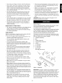
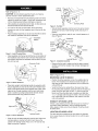
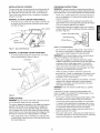
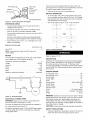
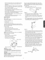
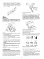
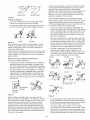
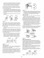
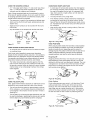
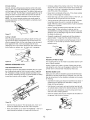
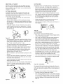
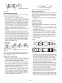
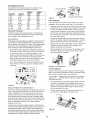
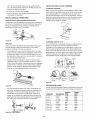
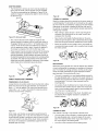
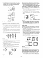
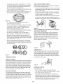
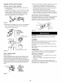
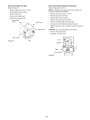


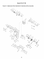

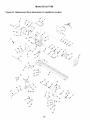


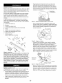
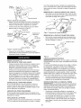
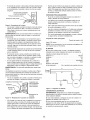
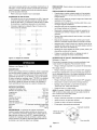
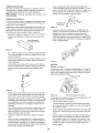
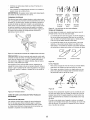
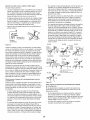
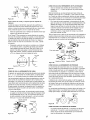
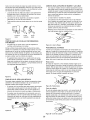
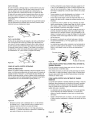
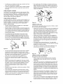
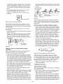
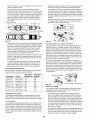
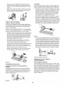
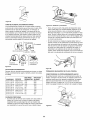
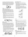
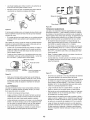
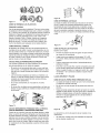
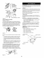
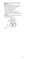


![MC55 User Guide [Spanish] (P/N 72E-108859](http://vs1.manualzilla.com/store/data/006902433_1-2583759d6d667e0860c8ad10d9f7e0c2-150x150.png)