1
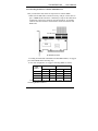
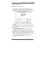
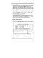
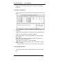
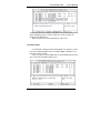
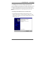
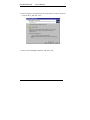
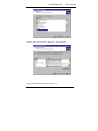
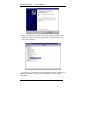
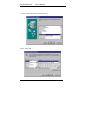
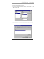
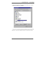
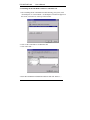
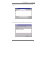
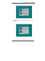
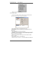
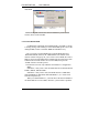
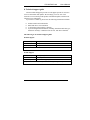
DC-200 RAID card
User’s Manual
Table of Contents
1. INTRODUCTION TO THE DC-200 RAID CARD........... 3
1.1 UNDERSTANDING RAID CONCEPTS.......................................... 3
1.2 OVERVIEW OF DC-200 RAID CARD........................................... 3
1.2.1 Features and specifications of the DC-200 RAID card ........... 5
1.3 SYSTEM REQUIREMENTS .......................................................... 6
2. HARDWARE INSTALLATION.......................................... 7
2.1 INSTALL DC-200 RAID CARD ................................................... 7
2.2 CONNECTING HARD DRIVES TO THE DC-200 RAID CARD .............. 9
3. BIOS CONFIGURATION ................................................. 11
3.1 BASIC BIOS SCREEN INFORMATION......................................... 11
3.2 BIOS FUNCTION ................................................................... 12
3.2.1 Set RAID configuration .................................................. 12
3.2.2 Delete RAID configuration .............................................. 13
3.2.3 Display configuration ..................................................... 14
3.2.4 Delete HDD partition...................................................... 14
3.2.5 HDD rebuild ................................................................. 15
3.2.6 Exit ............................................................................. 16
4. INSTALLING DRIVERS WITH AN EXISTING
OPERATING SYSTEM ......................................................... 17
4.1 INSTALLING THE DC-200 RAID CARD DRIVER IN WINDOWS 2000
17
4.2 INSTALLING THE DC-200 RAID CARD DRIVER IN WINDOWS 98 OR
E1/E43
DC-200 RAID card
User’s Manual
WINDOWS ME ...........................................................................23
4.3 INSTALLING THE DC-200 RAID CARD DRIVER IN WINDOWS NT ...28
5. INSTALLING DRIVERS WHEN INSTALLING THE
OPERATING SYSTEM..........................................................31
5.1 INSTALLING THE DC-200 RAID CARD DRIVER WHEN INSTALLING
WINDOWS 98 OR WINDOWS ME ...................................................31
5.2 INSTALLING THE DC-200 RAID CARD DRIVER WHEN INSTALLING
WINDOWS 2000 OR WINDOWS NT ................................................31
6. GUI (GRAPHIC USER INTERFACE) .............................32
6.1 GUI SETUP...........................................................................32
6.2 GUI FUNCTION .....................................................................35
6.2.1 GUI administrator ..........................................................35
6.2.2 GUI function menu ........................................................35
6.2.2.1 Monitor Open..............................................................36
6.2.2.2 Hard Disk Rebuild .......................................................38
6.2.2.3 Auto Rebuild Check......................................................39
6.2.2.4 Alwarys on Top ............................................................39
6.2.2.5 Flash Update ..............................................................39
6.2.2.6 GUI Tray Icon .............................................................39
6.2.2.7 Exit ...........................................................................39
7. TROUBLESHOOTING TIPS: ..........................................40
8. TECHNICAL SUPPORT GUIDE .....................................41
9. Glossary about DC-200 RAID CarFunction… … … … … 44
E2/E43
DC-200 RAID card
User’s Manual
1. Introduction to the DC-200 RAID card
1.1 Understanding RAID concepts
RAID stands for Redundant Array of Independent Disks. RAID is a
method of combining several hard drives into one logical unit. It can offer
more fault tolerance and higher throughput levels than a single hard drive or
a group of independent hard drives.
Benefits of RAID
?? Provides real-time data recovery with uninterrupted access when a
hard drive fails
?? Increases system uptime and network availability
?? Protects against data loss
?? Provides multiple drives working in parallel to increase system
performance
1.2 Overview of DC-200 RAID card
The DC-200 RAID card delivers data protection and increased
performance to individuals and companies operating ATA drives for
workstations, entry-level servers, and rackmount server environments. The
DC-200 RAID card supports up to 4 drives with a maximum transfer rate of
100 MBytes/sec per channel. Its low-profile form factor makes it ideal for
ISP environments –offering maximum space for other server components.
A user-friendly GUI interface also provides instant access to all your
storage management needs.
The DC-200 is designed to take advantage of the latest Ultra ATA
protocol, with TWO independent PCI IDE Bus Mastering channels. This
design enables high performance RAID with inexpensive IDE devices.
You can choose either RAID 0 (striping) to improve the performance,
RAID 1 (mirroring) to safeguard your important data or RAID 0+1 (striping
& mirroring) to gain the performance of RAID 0 and the fault tolerance of
RAID 1 at the same time.
RAID 0 stripes two independent Ultra ATA channels and therefore,
doubles the throughput. RAID 1 mirrors the main operational HDD to the
other and duplicates an exact copy of data to the mirrored HDD in real time.
The transfer rate of RAID 1 is the same as that of regular hard disk access.
E3/E43
DC-200 RAID card
User’s Manual
RAID 0+1 mirrors two striped disk arrays.
E4/E43
DC-200 RAID card
User’s Manual
1.2.1 Features and specifications of the DC-200 RAID card
Features
Mode support
Processor
BIOS
Max Transfer
Rate
PCI Interface
Max Devices
Accessory
included
Drivers
Available
Supported IDE
Devices:
? ? Supports RAID 0(striping), RAID
1(mirroring),RAID 0+1 (striping and
mirroring), JBOD mode
? ? Two independent IDE channels supporting up
to four Ultra ATA/100/66 drives
? ? Supports hot-swap to automatically rebuild
mirror array
? ? Up to 2 cards can co-exist in one system
? ? Easy-to-use GUI-based software for simple
monitoring and storage management
? ? RAID with ATA (2 HDDs RAID 0/1,1 HDD
ATA)
? ? Multi-RAID (2 HDDs RAID 0, 2 HDDs RAID
1)
? ? 1 card mode: ATA-100/66,RAID 0,RAID
1,RAID 0+1,JBOD, RAID with ATA,
Multi-RAID
? ? 2 cards mode: ATA-100/66, RAID 0, RAID 0+1
ARS106S, a PCI Dual Channel Ultra DMA/ATA
100 RAID Controller with 100MB/sec transfer rate.
Flash ROM
100 MB/Sec (Ultra ATA/100)
PCI 2.2 and backward compatible
4
2* ATA-100/66 cables
User’s Manual
Driver Diskette
GUI software
Windows 98SE/ME/NT/2000
Bus Width: 16-bit
Supported Devices: HDD
E5/E43
DC-200 RAID card
User’s Manual
1.3 System requirements
The minimum system requirements for the DC-200 RAID card are:
A Pentium II, 266 MHz Processor or higher system
A minimum of one ATA drive
64 MB or more of system memory
An available, unobstructed 5V PCI slot(PCI 2.2 or previous version
compliant) that supports Bus Mastering
Floppy disk drive
5 MB of free hard disk space for DC-200 RAID card
E6/E43
DC-200 RAID card
User’s Manual
2. Hardware installation
2.1 Install DC-200 RAID card
Before installing the DC-200 RAID card, please read through the
following procedures thoroughly. Also review your computer’s user manual
for the procedures covering controller card installation and cover removal.
Have the appropriate hand tools available so that you can remove your
computer’s cover and install the controller card.
To install the DC-200 RAID card in your computer, follow the steps
below:
1.
Before opening the cover, be sure that the power to the computer
system and all devices connected to it is OFF to avoid the risk of
dangerous electrical shock or damage to your equipment.
2.
Carefully remove your system’s cover (refer to your computer’s user
manual for the correct procedure).
3.
Locate a free PCI expansion slot for the card.
4.
If necessary, remove a system expansion slot cover by removing the
retaining screws and lifting it out.
5.
Hold the card by its top corner, and carefully line up the card with the
PCI expansion slot, securely insert the controller card.
6.
Secure the controller card with the screw that you removed in the
step above.
7.
Take the following steps to install hard disk drives.
E7/E43
DC-200 RAID card
User’s Manual
E8/E43
DC-200 RAID card
User’s Manual
2.2 Connecting hard drives to the DC-200 RAID card
After you install the card, follow the steps below to connect HDDs:
1. Make sure the IDE cable is inserted correctly, with pin 1 of the cable to
pin 1 of HDD and the card. Pin 1 is marked by a stripe on the cable and is
located next to the power connector on most hard drives. If your IDE
cable has one blue connector, this should be connected to the DC-200
RAID card.
According to installed DC-200 RAID card and HDD numbers, we suggest
you connect HDDs in the following way:
In one card configuration, we suggest connecting HDDs as follows:
HDD
number
IDE1
IDE2
PM
?
?
PS
1
2
3
4
?
?
?
?
SM
SS
?
?
?
?
In 2-card configuration, DC-200 supports 4 HDDs. We suggest
connecting HDDs as follows:
E9/E43
DC-200 RAID card
HDD
number
User’s Manual
Card 1
Card 2
IDE1
IDE2
IDE1
IDE2
PM PS SM
SS
PM PS SM SS
?
?
?
?
4
PM: Primary Master
PS: Primary Slave
SM: Secondary Master SS: Secondary Slave
2. After the steps above, please secure the system cover with the tools at hand.
E10/E43
DC-200 RAID card
User’s Manual
3. BIOS Configuration
3.1 Basic BIOS screen information
After you install the DC-200 RAID controller and HDDs in your
computer and boot your system, you will see the screen that displays
information about the cards and HDDs installed. Press <Ctrl +U> to enter
the ‘DC-200 ATA/100 RAID Controller Setup Utility’screen as follows:
The BIOS screen is divided into three parts: ’MENU’,’HELP’and
‘STATUS’.
The ‘MENU’window shows the function items from which you can
select to create RAID, delete RAID, display RAID, delete partition, rebuild
RAID and exit BIOS.
The ‘HELP’window shows relevant information when moving the
direction keys to different function items.
The ‘STATUS’window shows the location and status of currently
installed HDDs. For example: When 2 HDDs are installed with DC-200
RAID card, if RAID is not created, HDDs will be displayed as ‘ATA C0’,
‘ATA D0’. ’C0, D0’shows that 2 HDDs work as independent ATA devices.
If RAID 0 is created, HDDs will be displayed as ‘RAID 0, C0’, ‘RAID 0,
C1’. ‘C0, C1’means that 2 HDDs work as one virtual disk.
You can use the guide tools at the bottom of the screen to quit, move
direction keys and choose functions.
E11/E43
DC-200 RAID card
User’s Manual
3.2 BIOS function
3.2.1 Set RAID configuration
Choose ‘1. SET RAID CONFIGURATION’from the menu and press
‘Enter’, you will enter the ‘SET RAID CONFIGURATION’screen:
The HDDs installed will be highlighted. You can move the cursor to
HDDs and press the spacebar to select them. Press ‘Enter’to confirm
your selection and a new pop-up window will show RAID modes for you
to choose, there are four modes : JBOD, RAID 0, RAID 1, RAID
0+1.The following is some guidance to create RAID arrays:
1) In a configuration with one card
We will illustrate the available functions in the following tables:
HDD installed 1 HDD
Function
2 HDDs
3 HDDs
4 HDDs
JBOD
RAID 0
OK
OK
OK
2 HDD OK
RAID 1
RAID 0+1
OK
2 HDD OK
OK
2 HDD OK,
4 HDD OK
2 HDD OK
OK
a). When 1 HDD is installed, the HDD is automatically set as a standard
ATA, none of the RAID functions can work.
b). When 2 HDDs are installed, if both HDDs are selected, JBOD, RAID
E12/E43
DC-200 RAID card
User’s Manual
0, RAID 1 can be used.
c) When 3 HDDs are installed, if you select all connected HDDs at one
time, JBOD can be used. You can also select 2 HDDs to create a RAID 0
or RAID 1 array. This will be a RAID with ATA situation. In this
situation, RAID function and standard ATA can be supported at the same
time. We suggest that you select PM and SM to create a RAID 0 or RAID
1 array).
d). When 4 HDDs are installed, if you choose 4 HDDs at one time,
JBOD, RAID 0, RAID 0+1 can be used. You can also select 2 HDDs to
create a RAID 0 array and another 2 HDDs to create a RAID 1 array. This
situation is called Multi-RAID. We suggest that you select PM , SM to
create RAID 0 and PS , SS to create RAID 1.
2) In a configuration with two cards
In this configuration, DC-200 RAID card supports 4 HDDs. You can
select all connected HDDs to create RAID 0 or RAID 0+1. We suggest
that you select all connected HDDs to create RAID 0+1 array to enhance
system performance and increase data safety simultaneously.
3.2.2 Delete RAID configuration
Choose ‘2. DELETE RAID CONFIGURATION’in the menu and press
‘Enter’, you will enter ‘DELETE RAID CONFIGURATION’screen:
Please move the cursor and press spacebar to choose the RAID array
you want to delete. Then press ‘Enter’.
Note: Before you delete the selected RAID array, you must delete the
HDD partition based on the RAID array first. And the data on the selected
E13/E43
DC-200 RAID card
User’s Manual
RAID array will be damaged and can’t be restored after deleting the
RAID array.
3.2.3 Display configuration
Choose this function and it will display detailed information of RAID
arrays:
From the left to the right in the window, it will display the following
information:
HDD location: Where HDDs are connected, such as PM, SM, PS, SS.
HDD type: The manufacturer and model of HDDs.
HDD working mode: In which mode HDDs work, such as UDMA,
DMA and PIO.
HDD cable: Cable connected to HDDs and DC-200 card, such as
80P(ATA 100/66) and 40P(ATA 33).
HDD capacity: The capacity of connected HDDs.
HDD status: current status of HDDs, such as ATA, RAID 0, RAID 1,
RAID 0+1, JBOD.
If you press any key at this screen, it will return to the main menu.
3.2.4 Delete HDD partition
Choose this function to delete a HDD partition in the selected RAID
array:
E14/E43
DC-200 RAID card
User’s Manual
Please move the cursor and press spacebar to choose the RAID array on
which the HDD partition is created. Then press ‘Enter’to delete the
partition on the RAID array.
Note: All data in the selected RAID array will be lost.
3.2.5 HDD rebuild
If a Hard Disk is damaged when running RAID 1 or RAID 0+1 mode,
remove the damaged HDD, connect a workable HDD, rebuild the array
and restore data as needed.
After you replace a broken HDD with a workable HDD and select this
item, it will enter the HDD rebuild screen.
E15/E43
DC-200 RAID card
User’s Manual
You can move the cursor and press the spacebar to select source HDD
in the RAID array, after that, target HDD will be selected automatically.
And the system will remind you that data in the target HDD will be lost if
you continue this process. Press ‘y’to continue and a new window will
show the rebuilding speed, source HDD and target HDD.
Note:
In RAID 0+1 array with 1 card, the RAID structure is PM-SM, PS-SS
RAID 0, PM-PS, SM-SS RAID 1.
In RAID 0+1 array with 2 cards, the RAID structure is 0PM-0SM,
1PM-1SM RAID 0, 0PM-1PM, 0SM-1SM RAID 1. (0, 1 means card 1
and card 2 respectively).
When you rebuild RAID 0+1, you must choose the mirrored HDD of
the failed HDD to be source HDD, otherwise, system will have problem.
3.2.6 Exit
Select this item to exit DC-200 RAID card BIOS configuration
screen.
E16/E43
DC-200 RAID card
User’s Manual
4. Installing drivers with an existing Operating System
If you are adding the DC-200 RAID card to a computer where there is already
an operating system installed, follow these instructions to install the drivers.
Note: You shall install the device driver twice when 2 cards are installed
with an existing operating system. (It will automatically detect the cards
installed).
4.1 Installing the DC-200 RAID card driver in Windows 2000
1. After installing the DC 200 RAID card and rebooting your system,
Windows 2000 will show a ‘Found New Hardware’dialog box. A short
moment later, the ‘Welcome to the Found New Hardware Wizard’will be
displayed. Click ‘Next’.
E17/E43
DC-200 RAID card
User’s Manual
2. Choose ‘Display a list of known drivers for this device so that I can choose
a specific driver’and click ‘Next’.
3. Choose ‘SCSI and RAID Controllers’and click ‘Next’.
E18/E43
DC-200 RAID card
User’s Manual
4. In the ‘Select a Device Driver’dialog box, press ‘Have disk… ’
5. Insert DC 200 RAID card diskette in drive A:
E19/E43
DC-200 RAID card
User’s Manual
6. Click ‘Browse’, find ‘2000.inf’in directory ‘2000’in drive A and click
‘Open’, then. Click ‘OK’.
7. Choose ‘Tekram DC 200 ATA-100/RAID Controller’, then click ‘Next’.
8. In the ‘Start Device Driver Installation’dialogue box, click ‘Next’.
E20/E43
DC-200 RAID card
User’s Manual
9. The ‘Digital Signature Not Found’dialogue box will appear, ignore it and
click ‘Yes’to continue the installation.
10. Click ‘Finish’, remove the floppy disk from the computer and restart the
computer.
E21/E43
DC-200 RAID card
User’s Manual
11. After you restart your computer. Choose ‘My computer’and click right
button of the mouse, choose ‘System Properties’, click ‘Hardware’and
then ‘Device Manager’.
If you can see ‘Tekram DC-200 ATA/100 RAID Controller’under ‘SCSI
and RAID Controllers’, it means DC-200 RAID card driver is installed
successfully.
E22/E43
DC-200 RAID card
User’s Manual
4.2 Installing the DC-200 RAID card driver in Windows 98 or Windows
ME
The DC-200 RAID card driver installation will be the same with
Windows 98 and Windows ME. We will illustrate driver installation
procedure in Windows 98 as an example.
1. After installing the DC 200 RAID card and rebooting your system, the ‘Add
New Hardware Wizard’dialog box will be displayed. Click ‘Next’.
2. Choose ‘Display a list of all the devices in a specific location, so you can
select a driver you want’and click ‘Next’.
E23/E43
DC-200 RAID card
User’s Manual
3. Choose ‘SCSI Controllers’and click ‘Next’.
4. Press ‘Have disk… ’
E24/E43
DC-200 RAID card
User’s Manual
5. Insert DC 200 RAID diskette in drive A:
6. Click ‘browse’and find ‘DC200.inf’in directory ‘win9x’in Drive A, click
‘OK’, then click ‘OK’.
7. Choose ‘Tekram DC 200 ATA/100 RAID Controller’, then click ‘Next’.
E25/E43
DC-200 RAID card
User’s Manual
8. The dialogue box ‘Windows driver file search for the device’will appear on
the screen, click ‘Next’.
9. Click ‘Finish’, remove the floppy disk from the computer and restart the
computer.
E26/E43
DC-200 RAID card
User’s Manual
10. Choose ‘My computer’, click right button of the mouse, go to ‘System
Properties’and then ‘Device Manager’.
If you can see ‘Tekram DC-200 ATA/100 RAID Controller’under ‘SCSI
Controllers’, it means DC-200 RAID card driver is installed successfully.
E27/E43
DC-200 RAID card
User’s Manual
4.3 Installing the DC-200 RAID card driver in Windows NT
1. After installing the DC 200 RAID card and rebooting your system, click
‘SCSI Adapters’in ‘Control Panel’. ‘SCSI Adapters’window will appear on
the screen, click ‘Drivers’at the top of the window.
2. Click ‘Add’to install driver for Windows NT.
3. Click ‘Have disk… ’.
4. Insert DC-200 RAID card Installation diskette and click ‘Browse… ’
E28/E43
DC-200 RAID card
User’s Manual
5. Open ‘NT4’directory, then click ‘nt4.inf’and click ‘Open’, then click
‘OK’.
6. Click ‘Tekram DC-200 ATA/100 RAID Controller’and click ‘OK’.
E29/E43
DC-200 RAID card
User’s Manual
7. Click ‘Yes’to reboot your system.
After Rebooting, if you can see ‘Tekram DC-200 ATA/100 RAID Controller’
at ‘SCSI Adapters’of ‘Control Panel’, installation of DC-200 Driver is
successful.
E30/E43
DC-200 RAID card
User’s Manual
5. Installing drivers when installing the Operating System
If you are installing a new operating system on a freshly created array or hard
drive connected to the DC-200, follow these procedures.
5.1 Installing the DC-200 RAID card driver when installing Windows 98
or Windows ME
Install the operating system first. When the Windows 98 or Windows ME
setup is finished, the installation procedure for the DC-200 driver will be
the same as in an existing Windows 98 or Windows ME operating system.
(Please refer to 4.1)
5.2 Installing the DC-200 RAID card driver when installing Windows
2000 or Windows NT
You will install the driver during the operating system installation. Please
take the following steps to install the driver with the operating system.
1. Begin with the diskette installation or CD-ROM installation.You will see
a message like that underlined below when booting:
‘Setup is inspecting your computer’s hardware configuration… ’
Press ‘F6’a few times at this screen.
2. Press ‘S’at the following screen, then select ‘Other’and press ’Enter’.
3. Insert the DC-200 RAID card driver Installation diskette and the system
will search for the drivers automatically and show them on the screen.
4. Select drivers for the operating system (Windows NT or Windows 2000),
then install the driver.
5. After the driver installation procedure is complete, the installation of
Windows NT or Windows 2000 can continue normally.
After installing operating system and rebooting, if you can see ‘Tekram
DC-200 ATA/100 RAID Controller’at ‘SCSI Adapters’of ‘Control Panel’,
installation of DC-200 Driver is successful.
E31/E43
DC-200 RAID card
User’s Manual
6. GUI (Graphic User Interface)
GUI stands for Graphic User Interface. GUI function offers user-friendly
graphics in Windows operating systems for easy RAID array monitoring and
storage management. After you install the DC-200 RAID card and HDDs,
create RAID arrays in BIOS configuration, execute ‘FDISK’and ‘format’
command in DOS mode and install drivers for your operating system, you can
take the following steps to setup the GUI in Windows operating systems and
execute GUI functions.
6.1 GUI setup
You’d better set your screen display resolution rate as 800X600 or
1024X768 to avoid display abnormality during GUI setup.
1. After you power on your computer and bootup Windows, insert the GUI
disk into drive A.
2. Click ‘floppy (A:)’at ‘my computer’.
3. Execute Setup.exe which is located in the root directory.
E32/E43
DC-200 RAID card
User’s Manual
4. Click ‘Next’
5. If you want to install ‘DC-200 GUI Program’to a different directory,
click ‘Browse… ’.
6. Click ‘Next’
E33/E43
DC-200 RAID card
User’s Manual
7. Complete the installation by clicking ‘Next’
8. Choose ‘Yes, I want to restart my computer now’, click ‘finish’and then
restart the computer.
9. Click the ‘Start’button at the left bottom of your computer and go to the
directory ‘Program (P) -> Startup’.
You can see the ‘DC-200_GUI’icon in the ‘Startup’directory.
It starts automatically each time when you power on your computer.
E34/E43
DC-200 RAID card
User’s Manual
6.2 GUI function
The DC-200 GUI helps you monitor RAID function and status in
Windows operation systems. The DC-200 GUI has several functions such
as: Monitoring the RAID arrays ,Rebuilding RAID arrays in RAID 1 or
RAID 0+1 mode. The basic functions, including monitoring and warning
messages, are similar in all RAID modes. Here we will use a ‘1 card, 2
HDDs, RAID 1 array’configuration as an example to explain the functions
of the GUI.
6.2.1 GUI administrator
After you install one DC-200 RAID card and connect two HDDs with
PM and SM, create RAID 1 in BIOS configuration and start windows
system, GUI will start automatically. An administrator ( shown as above)
and the monitor window( we will explain it later) will be displayed on the
screen.
In the administrator, there are 4 icons which stand for PM, PS, SM and
SS from the left to the right. In the administrator above, the first icon and
third icon are green, it shows 2 HDDs are connected to PM and SM
respectively.
6.2.2 GUI function menu
Move the cursor onto the administrator and click the right botton of the
mouse, the function menu will appear as follows:
E35/E43
DC-200 RAID card
User’s Manual
There are seven items in this menu:
6.2.2.1 Monitor Open
Click this item and the monitor window will open. Each time when
GUI starts, monitor window will open automatically.
In the monitor window, it is divided into three parts:
In the left part, it shows the RAID array mode, HDD number and
HDD model.
In the right part, there are four sub-windows:
‘Mode Info’: This sub-window shows the information of current RAID
array, when you click the RAID array in the left of the window, it will
display in ‘Mode Info’sub-window:
RAID mode: The mode of disk arrays, such ATA, RAID 0, RAID 1,
RAID 0+1, JBOD.
Array capacity: Capacity of the RAID array.
HDD base capacity: Capacity of the smallest HDD in the RAID array.
E36/E43
DC-200 RAID card
User’s Manual
HDD number: HDD numbers in the RAID array.
Array number: the order of RAID array, for example, if 3 RAID arrays
are created, ‘Array number’of the arrays are respectively 0, 1 and 2.
‘HDD mode’: When you click the HDD logo in the left of the window,
this sub-window will show the detailed information of the HDD, such as
it’s location, cylinders, heads, sectors, model, serial number, HDD size,
UDMA support.
‘HDD rebuild’: In RAID 1 or RAID 0+1 configuration, if one HDD
crashes in RAID 1, one or two HDDs crash in RAID 0+1, you can do
RAID rebuild to restore data and recover RAID array in GUI. (We will
illustrate this function in detail in passage 6.2.2.2 Hard Disk Rebuild).
‘About’: This sub-window shows some information about Tekram
Technology Co.,Ltd, DC-200 RAID card, GUI version and the type of
E37/E43
DC-200 RAID card
User’s Manual
flash ROM.
In the lower part, it shows the status of RAID array, such as HDD
location, Event, Time and LBA.
6.2.2.2 Hard Disk Rebuild
If a Hard Disk is damaged when running RAID 1 or RAID 0+1 mode,
a warning message will remind you of the failed HDD, please remove the
damaged HDD, connect a workable HDD and rebuild the array.
After you replace a broken HDD with a workable HDD and select
‘Hard Disk Rebuild’function, the ‘HDD Rebuild’sub-window in the
monitor window will pop up for you to select a source HDD, after source
HDD is selected, target HDD will be automatically detected. Please click
a HDD in the left of the window to be source HDD, then press the
‘START’botton to start this process.
This function can work only in RAID 1 and RAID 0+1 configuraiton.
Note:
In RAID 0+1 array with 1 card, the RAID structure is PM-SM, PS-SS
RAID 0, PM-PS, SM-SS RAID 1.
In RAID 0+1 array with 2 cards, the RAID structure is 0PM-0SM,
1PM-1SM RAID 0, 0PM-1PM, 0SM-1SM RAID 1. (0, 1 means card 1
and card 2 respectively).
When you rebuild RAID 0+1, you must choose the mirrored HDD of
the failed HDD to be source HDD, otherwise, system will have problem.
E38/E43
DC-200 RAID card
User’s Manual
6.2.2.3 Auto Rebuild Check.
When the RAID array is RAID 1 or RAID 0+1, if a HDD fails, ‘Auto
Rebuild Check’funciton can detect the failed HDD automatically and
notify you to replace it with a workable HDD to rebuild the RAID array.
This is a method to rebuild RAID arrays automatically. There are hint
messages to guide you through the process. You can enable or disable this
funciton by clicking this item in the function menu.
6.2.2.4 Alwarys on Top
This item can make the administrator which illustrate the connected
HDD location always on the top of the screen. You can enable or disable
this funciton by clicking this item in the function menu.
6.2.2.5 Flash Update
You can update your BIOS to a new version in GUI. This is a more easy
and user-friendly operation than BIOS update in DOS mode. After you
select this item, the ‘Flash ROM Update’window will appear, you can
choose the new BIOS file and press ‘Flash ROM Update’bar to ugdate
old version BIOS.
6.2.2.6 GUI Tray Icon
Click this item and the administrator on top of the screen will become a
small tray icon in the task bar. Click the tray icon in the task bar and it will
become administrator on top of the screen again.
6.2.2.7 Exit
Click this item to close all GUI display sreens and functions.
E39/E43
DC-200 RAID card
User’s Manual
7. Troubleshooting tips:
The following tips are general troubleshooting procedures:
1. Check that the DC-200 RAID card is seated evenly all the way into the PCI
slot.
2. Check that the PCI expansion slot is 5V and compliant with PCI 2.2 or
previous version and supports Bus Mastering.
3. Check that DC-200 ATA 100 RAID card is detected during booting by
looking for the BIOS message from the screen. If it is not detected, try to
move it to another free PCI slot.
4. Check that all ATA cables and power cables are connected properly.
E40/E43
DC-200 RAID card
User’s Manual
8. Technical support guide
Tekram Technical Support provides several support options for our users
to access information and updates. We encourage you to use one of our
electronic services which provide product information updates with the most
efficient service and support.
If you want to contact us, please have the following information available:
??
??
??
??
Product model and serial number
BIOS and driver version numbers
A description of the problem / situation
System configuration information, including: mainboard and CPU type,
hard drive model(s), ATAPI drives & devices, and other controllers.
The following is our technical support guide:
Website support
Taiwan(headquarters)
http://www.tekram.com.tw
US
http://www.tekram.com
Europe
http://www.tekram.de
We provide tech documents, drivers, utilities, etc in our websites.
E-mail Support
Taiwan(headquarters) [email protected]
US
[email protected]
Europe
[email protected]
Any question concerned with our products will be given a quick response.
E41/E43
DC-200 RAID card
User’s Manual
9. Glossary about DC-200 RAID card functions
RAID:
Abbreviation of Redundant array of independent disks. It is a set of disk
array architectures that provides fault-tolerance and improve performance.
RAID 0(striping):
An array where data is distributed, or striped , across the disks in the
array.
If 2 HDDs are configured as RAID 0, data can be processed into 2
HDDs simultaneously to double system throughput rate, if 4 HDDs are
configured as RAID 0, data can be processed into 4 HDDs simultaneously
to make system throughput rate 4 folds. It offers the best performance but
no fault-tolerance. The capacity of RAID 0 will be double the size of the
smaller HDD when 2 HDDs create one RAID 0 and 4 times the size of the
smallest HDD when 4 HDDs create one RAID 0, so we suggest you connect
HDDs of the same sizes to save HDD space.
RAID 1(mirroring):
An array which uses a single pair of disks. Both disks in the pair contain the
same data It provides the best data protection but can’t improve system
performance. And storage space for the same data capacity should be double
than in general cases. Hence storage cost doubles. The capacity of RAID 1
will be the size of the smaller HDD, so we suggest you connect HDDs of the
same sizes to save HDD space.
RAID 0+1(striping and mirroring):
When 4 HDDs are configured as RAID 0+1, it will do striping and
mirroring simultaneously, hence, it has double function of increasing system
performance and enhancing data safety. But storage space for the same data
capacity should be double than in general cases. Hence storage cost doubles.
The capacity of RAID 0+1 will be double the size of the smallest HDD, so we
suggest you connect HDDs of the same sizes to save HDD space.
Rebuild:
In RAID 1 or RAID 0+1 mode, if one HDD fails, it can be replaced with a
workable HDD to restore data and recover RAID array to protect data safety.
JBOD:
E42/E43
DC-200 RAID card
User’s Manual
It is the abbreviation of “Just a Bundle of Disks”. In JBOD mode, several
physical devices are mapped as one virtual device. When processing data, data
will not be saved in the following disk until current disk space is completely
occupied. JBOD can’t increase fault tolerance or improve data access
performance, but it avoids waste of disk space
Multi-RAID:
Installing one DC-200 card and connecting 4 HDDs, it allows creating
two RAID arrays. For example, configure 2HDDs in RAID 0 and
configure the remaining 2HDDs in RAID1.
RAID with ATA:
Installing one DC-200 card and connecting 3 HDDs, two HDDs can be set
as RAID 0 or RAID 1 and the rest one HDD is used as a standard ATA disk.
Hot swap:
While the system is still operating, if a HDD fails, it can be removed and
replaced with a workable HDD without powering off the system. This
function only works in RAID 1 or RAID 0+1 configuration.
Website: www.tekram.com.tw
27-0M0200-07
E43/E43