1
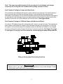
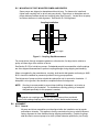
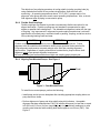
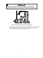
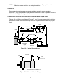
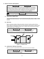
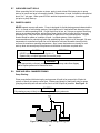
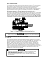
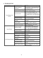
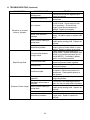
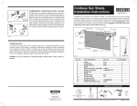
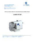
GENERAL INSTALLATION, OPERATION,
MAINTENANCE AND TROUBLESHOOTING MANUAL
FOR
THREE SCREW AND CIG SERIES PUMPS
WARNING
This manual, and the pump specific Product Service Manual, should be read thoroughly
prior to pump installation, operation, maintenance or troubleshooting.
CAUTION
ATTENTION
Page 2 of this manual has been added to emphasize the
requirements of filling and venting the seal chamber prior to starting
pump to prevent seal leakage and failures.
Manual No. SRM00046
Rev. 08 (14-0327)
AUGUST 2014
Imo Pump
1710 Airport Road
PO Box 5020
Monroe, NC USA
28111.5020
Tel: +1.704.289.6511
Email: [email protected]
Web: colfaxcorp.com
1
Note: This page was added because of the prevalence of seal damage and leakage
caused by not venting the seal chamber before putting a pump in service.
Seal Chamber Priming for Pumps with Seal Vents:
Fill mechanical seal chamber with liquid to insure seal does not start dry. This can be done by
removing seal vent set-screw and pouring fluid into seal vent before opening pump inlet.
Alternately, seal chamber can be vented in situations where inlet pressure is above atmospheric
by opening inlet and discharge valves and then loosening seal vent plug to allow positive inlet
pressure to push air out of seal chamber until oil flows from it. See Figure Below.
Seal Chamber Priming for 3E Model Pumps with Mechanical Seals:
For the Imo 3E Model pumps with mechanical seals, there is no seal vent port. The mechanical
seal in these model pumps is located in the discharge chamber of the pump and is in the fluid
flow path. In these model pumps the complete pump must be filled and vented of any trapped
air prior to starting the pump. Contact the factory if you have questions. See Figure 8 on page
12 and Figure 12 on page 18 of this manual for suction piping and pump filling methods.
Filling or Venting Seal Cavity Using Seal Vent
CAUTION
- Failure to fill or vent seal chamber as described above may cause damage to seal
running faces which may result in seal leakage.
2
READ THIS ENTIRE PAGE BEFORE PROCEEDING
FOR SAFETY OF PERSONNEL AND TO PREVENT DAMAGE TO EQUIPMENT, FOLLOWING
NOMENCLATURE HAS BEEN USED IN THIS MANUAL:
DANGER
Failure to observe precautions noted in this box can result in severe bodily injury or loss of life.
WARNING
Failure to observe precautions noted in this box can cause injury to personnel by accidental contact
with equipment or liquids. Protection should be provided by the user to prevent accidental contact.
CAUTION
ATTENTION
Failure to observe the precautions noted in this box can cause damage or failure of the equipment.
Non compliance of safety
instructions identified by following
symbol could affect safety for
persons:
Safety instructions where
electrical safety is involved
are identified by:
Safety instructions which shall
be considered for reasons of
safe operation of pump and/or
protection of pump itself are
marked by sign:
ATTENTION
ATTENTION
If operation of this pump is critical to your business, we strongly recommend you keep a spare pump or
major repair kit in stock at all times. As a minimum, a minor repair kit (o-rings, gaskets, shaft seal and
bearings) should be kept in stock so pump refurbishment after internal inspection can be accomplished.
CONTENTS
SAFETY AND TABLE OF CONTENTS .......................................................................................3
A - GENERAL .............................................................................................................................4
B - TRANSPORTATION AND STORAGE ...................................................................................4
C - DESCRIPTION OF THE PUMP .............................................................................................4
D - INSTALLATION/ASSEMBLY .................................................................................................4
E - STARTUP, OPERATION AND SHUTDOWN.......................................................................16
F - MAINTENANCE...................................................................................................................20
G - FIELD AND FACTORY SERVICE .......................................................................................22
H - TROUBLESHOOTING ........................................................................................................23
3
APPLICATIONS MANUAL FOR IMO PUMPS
A. GENERAL
Instructions found herein cover general installation, operation, maintenance and troubleshooting of
subject equipment. NOTE: Individual contracts may have specific provisions that vary from this
manual. Should any questions arise which may not be answered by these instructions, refer to
specific pump instruction manual provided with your order. For further detailed information and
technical assistance to questions not answered by these manuals, please refer to Imo Pump,
Technical/Customer Service Department, at (704) 289-6511.
This manual cannot possibly cover every situation connected with installation, operation,
maintenance and troubleshooting of equipment supplied. Every effort was made to prepare text of
manual so that engineering and design data was transformed into easily understood wording. Imo
Pump must assume personnel assigned to operate and maintain supplied equipment and apply
instruction manual have sufficient technical knowledge and experience to use sound safety and
operational practices which may not be otherwise covered by this manual.
In applications where equipment furnished by Imo Pump is to become part of a process or other
machinery, these instructions should be thoroughly reviewed to determine proper fit of equipment into
overall plant operational procedures.
WARNING
If installation, operation, and maintenance instructions are not correctly and strictly
followed and observed, injury to personnel or serious damage to pump could result.
Imo Pump cannot accept responsibility for unsatisfactory performance or damage
resulting from failure to comply with instructions.
B. TRANSPORTATION AND STORAGE
Always protect the pump against taking in water and other contaminants. Store the pump in a clean,
dry and relatively warm environment. Pumps are delivered with their internals oiled (unless specified
otherwise by the customer order) and with protective covers in or over all openings. These covers
should remain in place during the mounting and alignment procedures. The covers must be removed
just prior to attaching system piping to pump. If pumps are to be stored in other than a clean, warm,
or dry environment, or if they are to be stored for more than six months, contact Imo for appropriate
storage procedures.
C. DESCRIPTION OF THE PUMP
See specific pump instruction manual provided with your order.
D. INSTALLATION / ASSEMBLY
WARNING
On critical or dangerous equipment, provide safety and emergency systems to protect
personnel and property from injury due to pump malfunction. If pumped liquids are
flammable, toxic, corrosive, explosive or otherwise hazardous, provide for safety in the
event of leakage or malfunction. BEFORE working on equipment, make sure all power
to equipment is disconnected and locked-out.
4
D.1 TOOLS
Procedures described in this manual require common mechanics hand tools, dial indicators for
alignment and suitable lifting devices such as slings, straps, spreader bars, etc.
D.2 LIFTING OF PUMP AND PUMP/DRIVER ASSEMBLIES
All pumps and pump/driver assemblies should be lifted with appropriate devices securely
attached to whole unit. Ensure unit’s center-of-gravity is located between lifting points. See
Figure 1. This will avoid tipping of pump or pump/driver assembly. Spreader bars should be
used as necessary to insure load is properly distributed and lifting straps do not damage
equipment.
Some pumps and pump/driver assemblies have designated lifting points that are shown on their
outline drawings.
DANGER
ATTENTION
Lifting a vertical pump/driver using straps or hooks attached to the pump or pumpto-driver bracket may be dangerous since the center-of-gravity of the assembly
may be higher than the points of attachment. Take precautions to prevent
slippage of slings and hooks. Always use properly rated lifting devices.
Max 90°
Min 60°
Max 90°
Min 60°
Max 90°
Figure 1 – Lifting Pumps and Pump/Driver Assemblies
D.3 INSTALLATION OF PUMP ASSEMBLY
To insure adequate flow of liquid to pump’s inlet port, place pump near liquid source and
preferably place pump centerline below liquid surface. Use short, straight inlet lines.
A dry, clean, well-lit and well-ventilated site should be selected for installing the pump
assembly.
Sufficient open space should be provided around pump rotor and/or gear housing to permit
routine visual inspection, on-site service and maintenance, and pump replacement. For
installation and servicing of large pump units, ample overhead clearance should be provided to
allow for lifting device maneuvering.
D.4 FOUNDATIONS AND BASEPLATES
Foundations and baseplates must be designed and installed so pump and driver alignment can
be maintained at all times. Be sure baseplates are level and rest on smooth flat surfaces.
Small pumps may be mounted on baseplates or directly to existing floors that meet the criteria
of foundations. Larger pumps and/or drivers must be mounted to baseplates and foundations.
It is recommended that pumps and their drivers be mounted on common baseplates.
5
D.5 MOUNTING OF FOOT MOUNTED PUMPS AND DRIVERS
Some pumps are shipped on baseplates without drivers. For these units, install and
tighten each coupling half on driver and pump shafts. Place driver on baseplate and set
proper distance between shafts and coupling hubs (See Figure 2). Locate driver so pump
and driver shafts are in axial alignment. See Section D.6 on Alignment.
Coupling Installation
Gap Length
Figure 2 – Coupling Gap Measurement
For pumps driven through a separate gearbox or other device, first align device relative to
pump, and then align driver relative to device.
See Section D.6.5 for belt-driven pumps. On horizontal pump/driver assemblies, shaft couplings
are often shipped disassembled to prevent coupling damage during shipping and handling.
When not supplied by the manufacturer, coupling, shaft and/or belt guards conforming to ANSI
B15.1 should be installed for personnel protection during pump operation.
Final alignment of pump and driver should take place after unit is secured to foundation. If
baseplate is to be grouted, this should be completed before final alignment.
NOTE: Grouting is recommended to prevent lateral shifting of baseplate, not to take up
irregularities in the foundation. For installations requiring grouting, a baseplate
designed specifically for this purpose is needed.
WARNING
Install guards over couplings and shafts to protect personnel from accidental
contact with rotating couplings, belts, sheaves, chains, shafts and/or keyways.
D.6 ALIGNMENT
D.6.1 General
All pump and driver assemblies must be aligned after site installation and at regular
maintenance intervals. This applies to factory-mounted units (new or rebuilt) because
factory alignment is often disturbed during shipping and handling. Flexible couplings
shall be used to connect pump to its driver (unless otherwise specified by Imo Pump).
6
The objective of any aligning procedure is to align shafts (not align coupling hubs) by
using methods that cancel out any surface irregularities, shaft-end float, and
eccentricity. At operating temperatures above 175o F (65o C), pumps require “hot
alignment” after pump and driver reach normal operating temperatures. Also, re-check
final alignment after all piping is connected to pump.
D.6.2 Flexible Shaft Couplings
Flexible couplings are intended to provide a mechanically flexible connection for two
aligned shaft-ends. Flexible couplings are not intended to compensate for major
angular or parallel shaft misalignment. The allowable misalignment varies with the type
of coupling. Any improvement in alignment beyond coupling manufacturer’s minimum
specification will extend pump, mechanical seal or packing, coupling, and driver service
life by reducing bearing loads and wear.
CAUTION
ATTENTION
• Flexible couplings are NOT intended to permit significant shaft misalignment. Proper
alignment must be established/maintained to obtain proper operation and maximum life.
• Pump alignment requirements are nearly always more strict than coupling alignment
requirements. Regardless of coupling manufacturer’s stated limits, pump-to-driver shaft
alignment must be per pump’s alignment requirement.
• Be sure all coupling set-screws and bolts are tight and coupling gap is properly set.
D.6.3 Aligning Foot Mounted Pumps - See Figure 3
Feet
Figure 3 – Foot Mounted Pump
To install foot mounted pumps, perform the following:
• Install pump and driver onto baseplate after installing appropriate coupling halves on
pump and driver shafts.
• Perform alignment of pump and driver shafts using dial indicators. Acceptable
alignment has been attained when FIM (Full Indicator Movement) is less than or equal
to 0.005 inch (0.13 mm) for face (angularity) and rim (parallelism) readings at or near
coupling outer diameter while rotating both shafts together one full turn (360°). See
Figure 4.
7
Dial Indicator
Dial Indicator
X1
Y
θ
X2
A. Face Check (Angularity)
Rotating both shafts together for one full turn, align
pump and driver until shaft centerlines are parallel
(θ = 0, X1 = X2) within 0.005 inch (0.13 mm) FIM.
B. Face Check (Parallelism)
Rotating both shafts together for one full turn, align
pump and driver until shaft centerlines coincide (Y - 0))
within 0.005 inch (0.13 mm) FIM.
Figure 4 – Coupling and Hub Alignment
D.6.4 Aligning Flange Mounted Pumps and Drivers - See Figure 5
Mounting Flange
Figure 5 – Flange Mounted Pump
Shaft alignment requirements for flange mounted pumps are the same as for foot
mounted pumps. That is, shafts must be aligned within 0.005 inch (0.13 mm) FIM (Full
Indicator Movement) for face (angularity) and rim (parallelism) at or near coupling outer
diameter while rotating both shafts together one full turn (360°).
When a pump and driver are both flange mounted to a bracket, DO NOT assume bracket
will automatically align shafts to the above requirements. Brackets must be designed to
obtain/maintain required alignment as well as to support pump weight plus any (small)
residual piping forces without distorting. If at all possible, bracket design should include
adequate room to check shaft alignment with dial indicators with both pump and motor
mounted onto bracket. See Figure 4. If this is not possible, align bracket to driver shaft
(see Figure 6), then attach pump to bracket (assumes pump fits snugly into its mounting
bore in the bracket).
8
After pump-bracket-driver is installed into system and after piping is connected to pump,
shaft alignment should be re-checked and adjusted, if necessary,
When a right-angle foot bracket is used, mount pump onto bracket and tighten pump-tobracket mounting bolts. At this point, bracket base, in effect, becomes pump feet.
Continue with aligning procedure as if pump were foot mounted. See Section D.6.3.
Driver
Mounting Bracket
Flange Mounted Pumps
Dial Indicator
B
Locating bore (A) must be concentric to
driver shaft centerline within 0.002 inch
FIM. Mounting surface (B) must be
perpendicular to driver shaft centerline
within 0.002 inch (0.05 mm) FIM.
A
Figure 6 – Alignment of Flange Mounted Pumps
CAUTION
ATTENTION
• Be sure all coupling set screws and bolts are tight and coupling gap is properly set.
• Install safety shield(s) or plate(s) over bracket opening(s).
D.6.5 Belts and Sheaves
It is only acceptable to belt drive Imo pumps that are specifically designed for this
purpose. It is generally not acceptable to belt drive pumps with ratings in excess of 600
psi differential pressure. Contact Imo if not sure a particular pump can be belt
driven.
Belts and sheaves must be properly selected aligned and tensioned to minimize belt
wear, eliminate possibility of belt turnover in sheave grooves, and avoid excessive side
load on pump shaft. Adjustable slide rails mounted under driver are recommended for
proper belt tensioning.
Check belt tension frequently during first 24 to 48 hours of run-in operation. Follow belt
drive manufacturer’s recommendations for alignment of sheaves and belt-tension
settings.
CAUTION
ATTENTION
Loose, slipping belts will squeal and cause overheating of sheaves leading to reduced
belt life. Excessively tightened belts will result in reduced belt and bearing life and
possible bearing or shaft failure.
9
D.7 PIPING AND VALVES
D7.1
General
Piping connected to pump MUST be independently supported and not allowed to
impose strains on pump casing including allowing for expansion and contraction due to
pressure and temperature changes.
To prevent foaming and air entrainment, all return lines in recirculating systems should
end well below liquid surface in reservoir. Bypass liquid from relief pressure and flow
control valves should be returned to source (tank, reservoir, etc.), NOT pump inlet line.
Shut-off valves should be installed in both suction and discharge lines so pump can be
hydraulically isolated for service or removal. All new piping should be flushed clean
before connecting to pump.
CAUTION
ATTENTION
• Pipe strain will distort a pump. This could lead to pump and piping malfunction or failure.
• Return lines piped back to pump can cause excessive temperature rise at pump which
could result in catastrophic pump failure.
D.7.2 Variable Frequency Drives (VFD)
When utilizing VFD’s with positive displacement pumps, consideration must be given to
the minimum and maximum speed range intended for the pumping application.
Maximum speed must consider the inlet pressure available for the fluid viscosity range.
The minimum operating speed is dependent on the minimum operating viscosity and
associated discharge pressure.
When starting positive displacement pumps with VFD’s, there will be a delay from the
initial start until the motor reaches the selected minimum operating speed. In some
applications, such as crude oil pipeline transfer, the pump needs to be operated in full
fluid bypass mode through a control valve loop during the VFD speed ramp-uptime.
Once the minimum operating speed is attained, the control valve should completely
close and the system operated as intended. The time delay should be relatively short,
approximately 30 seconds to two minutes. For system shut down, it is recommended
this procedure be followed in reverse order. If a pump is to be driven by a VFD, this
detail should be addressed during the pump selection process. Contact Imo Pump if
there are any questions concerning VFD operation with positive displacement
pumps.
D.7.3 Relief Valve
Use relief valves to protect pumps from overpressure. They need to be connected to
pump discharge lines as close to pumps as possible and with no other valving between
pumps and relief valves. Relief valve settings should be set as low as practical.
DO NOT set relief valve higher than maximum pressure rating of pump, including
pressure accumulation at 100% bypass. Relief valve return lines should NOT be piped
into pump inlet lines because they can produce a loop that will overheat pump. See
Figure 7.
10
DANGER
The Imo pump is a positive displacement type. It will deliver (or attempt to deliver)
flow regardless of back-pressure on unit. Failure to provide pump overpressure
protection can cause pump or driver malfunction and/or rupture of pump and/or piping.
Relief Valve
Figure 7– Proper Relief Valve Return Line Arrangement
Some low pressure pump models include built-in safety relief valves. They are intended
only for emergency operation, NOT for system control. Extended operation of relief
valves in these pumps could lead to pump damage or failure.
11
D.7.4 Suction Line
Suction line should be designed so pump inlet pressure, measured at pump inlet flange,
is greater than or equal to minimum required pump inlet pressure (also referred to as
Net Positive Inlet Pressure Required or NPIPR). Suction line length should be as short
as possible and equal to or larger than pump’s inlet size. All joints in suction line must
be tight and sealed. If pump cannot be located below liquid level in reservoir, position
suction line or install a foot valve so liquid cannot drain from pump while it is shut down.
See Figure 8. When pump is mounted vertically with drive shaft upward, or mounted
horizontally with inlet port opening other than facing upward, a foot valve or liquid trap
should be installed in suction line to prevent draining. Suction line should be filled
before pump start-up.
CAUTION
ATTENTION
DO NOT operate pump without liquid or under severe cavitation.
Filling
Port
Filling
Port
Foot
Valve
Liquid Trap
Figure 8 – Fluid Trap and Foot Valve Arrangements for Vertical Pumps
12
D.7.5 Suction Strainer /Filter
Pump life is related to liquid cleanliness. Suction strainers or filters should be installed
in all systems to prevent entry of large contaminants into pump. See Figure 9.
Purpose of a suction strainer or filter is for basic protection of internal pumping
elements. It should be installed immediately ahead of inlet port. This location should
provide for easy cleaning or replacement of strainer element. Appropriate gages or
instrumentation should be provided to monitor pump pressure. Pressure drop across a
dirty strainer must not allow inlet pressure to fall below NPIPR. General guidelines for
strainer sizing are as follows:
When pumping relatively clean viscous liquids (over 5000 SSU), use 10 to 12 mesh
screens or those with about 1/16 inch (about 1 ½ mm) openings.
When pumping relatively clean light liquids such as distillate fuels, hydraulic oil and light
lube oils, use suction strainers of 100 to 200 mesh.
When pumping heavy crude oils, use 5 to 6 mesh strainer screens or those with about
1/8 inch (3 mm) openings.
When pumping relatively clean distillate fuels in high pressure fuel supply systems, use
25 micron “absolute” filters for three screw pumps and 10 micron “absolute” filters for
gear pumps.
Make sure size/capacity of strainer or filter is adequate to prevent having to clean or
replace elements too frequently.
CAUTION
ATTENTION
Before connecting pump to system, all system piping must be thoroughly flushed to
remove debris which accumulates during fabrication, storage, and installation. Imo
pumps should not be used for flushing. One large, hard particle may cause internal
damage, possibly requiring a pump overhaul. Pay particular attention to suction
line between suction strainer and pump to be sure it is clean.
Pressure Gage
Valves
Pressure Gage
Strainer
Figure 9 - Ideal Strainer Arrangement
13
D.7.6 System Filtration
In systems that recirculate pumped liquid, downstream (pressure and/or return side)
filtration should be installed. Downstream filters may also be required to protect
components such as servo valves in hydraulic systems or high-pressure fuel nozzles
and flow dividers in fuel oil supply systems for gas turbines. System’s most
contamination-sensitive component determines its liquid cleanliness requirement. For
optimum Imo pump life when running on fuel oil, light lube oil, hydraulic oil and other
relatively low viscosity (thin) liquids, a high efficiency 10 micron “absolute” or finer filter
is recommended. This same filter rating is recommended for pumps running at extreme
operating conditions and/or in harsh environments. For pumps running on relatively
clean, more viscous (thicker) liquids, filter ratings as high as 25 micron “nominal” may be
acceptable as long as operating conditions and the operating environment are
moderate. Imo should be contacted for filtration requirements for pumps running
on very low viscosity (water thin) and low lubricity as well as for those with an
unusually large quantity of contaminants.
System builder determines filter size (dirt holding capacity) by amount and size of
contamination expected to be produced by system and other external contamination
sources, by allowable pressure drop across filter and by acceptable frequency for
cleaning/replacing filter elements.
D.7.7 Outlet Piping
In general, outlet piping should be sized to accommodate pump’s flow rate while
minimizing pipe friction losses. It should also be designed to prevent gas and air
pockets. Piping downstream of pump should include a vent at highest point in system to
allow air to escape during priming.
D.8 SHAFT PACKING AND SEAL LEAKAGE
Pump should be installed so any leakage from shaft packing or shaft seal does not become a
hazard. Packing leakage should be about 8 to 10 drops per minute. A small amount of liquid
may also leak from mechanical or lip seals (usually less then or equal to 10 drops per hour).
Provisions should be made to collect leakage from packing or shaft seals.
WARNING
DANGER
If not appropriately collected, packing leakage may make floor slippery or expose
personnel to hazardous fluids.
D.9 QUENCHED SHAFT SEALS
Some pumps include quenched mechanical shaft seals. For these pumps, a low pressure
stream of steam, nitrogen, or clean water is supplied from an external source to atmospheric
side of seal faces.
Quenching is used in selected seal applications to:
•
•
•
•
Heat or cool seal area.
Prevent build up of coke formations by excluding oxygen.
Flush away undesirable material build-up around dynamic seal components.
When quenched mechanical seals are part of pump assembly, an appropriate quenching
stream must be supplied by user.
14
NOTE: Refer to pump or pump/driver outline drawing and/or specific pump’s instruction
manual for quench connection size and port locations.
D.10 GAGES
Pressure and temperature gages are recommended for monitoring pump’s operating
conditions. These gages should be easily readable and placed as close as possible to pump’s
inlet and outlet flanges. See Figure 10a.
D.11 IDEALIZED INSTALLATION FOR PUMPS LOCATED ABOVE LIQUID LEVEL
Figures 10a and 10b are compilations of Figures 7, 8 and 9 showing good-practice installation
schemes for pumps located above the liquid reservoir in systems that recirculate the pumped
liquid.
Valves
SYSTEM
Relief Valve
Temperature
Gage
Filter
Pressure Gages
Filling
Port
Pressure Gages
Valves
Outlet
Suction
Strainer
Temperature
Inlet Trap
Gage
Reservoir
Figure 10a – Vertical Mounted Pump
Filling Port
Outlet
Inlet
Same as Figure 10a
Same as Figure 10a
Seal or Package Leakage Drain Line
Figure 10b - Horizontal Mounted Pump
15
E. Startup, Operation and Shutdown
CAUTION
ATTENTION
Operation conditions, such as speed, liquid viscosity, temperature, inlet pressure,
discharge pressure, filtration, duty cycle, drive type, mounting, etc., are interrelated.
Due to these variable conditions, specific application limits may be different from
pump’s operating and structural limits. Equipment must not be operated without
verifying system’s operating requirements are within pump’s capabilities.
DANGER
Make sure all power equipment is disconnected and locked-out before proceeding.
E.1 ELECTRICAL CONNECTIONS
Verify electrical requirements for driver match electrical supply with respect to voltage, number
of phases and terminal connections. Also, check that driver has been wired to rotate in correct
direction.
E.2 ROTATION
Before connecting couplings, check pump rotation to be sure it matches rotation of driver.
When coupling is connected and shafts are correctly aligned, pump should turn freely by hand.
Rotation direction is indicated by an arrow cast on casing or by an attached plate showing a
rotation direction arrow. See Figure 11.
CAUTION
ATTENTION
Operating pump in reverse direction may cause pump damage. Make sure
rotation direction is not confused with inlet or outlet flow direction arrows.
Outlet
Arrow
Inlet
Arrow
Rotation
Arrow
Figure 11 – Rotation Arrow
E.3 HYDROSTATIC TESTING THE SYSTEM
Before any system is hydrostatically tested, pump must be removed or isolated.
CAUTION
ATTENTION
To prevent damage to pump, it is necessary to remove or isolate it from the
system prior to starting hydrostatic testing.
16
E.4 PROTECTIVE DEVICES
E.4.1 General
Automatic shutdowns, emergency switches, and similar controls should be part of
pumping system. They are generally supplied by system supplier or user.
E.4.2 Covers and Guards
Before start-up, insure all protective-covers and guards are in place.
WARNING
DANGER
To protect personnel from accidental contact with rotating couplings, sheaves,
belts, shaft keys, keyways, etc., install the following covers or guards over:
• Bracket openings on flange mounted pumps.
• Couplings and shafts on foot mounted pumps.
• Sheaves, gears, chains, belts or other type drives.
E.4.3 Valves
Check all valves, especially those that are manually operated, to be sure they are in
proper position. Check that there is no possibility of starting pump with a blocked
suction or discharge line.
WARNING
Starting a pump with discharge line blocked and without adequate relief protection
will cause catastrophic pump failure and possible injury to personnel.
E.5 INTERMEDIATE DRIVE LUBRICATION
Some Imo pump units include intermediate gearboxes or other devices between pump and
driver. When these devices are present, lubrication is required. Add lubricant to specified level
per device manufacturer’s recommendations before start-up.
E.6 HEATING JACKETS
Some pumps require heating before start-up. See Section E.12 on Thermal Shock and
Operating Temperature Limits. This is usually done with steam, hot water, heat transfer fluid or
electric heat strips. Some pumps are fitted with heating jackets (sometimes called steam
jackets). Where electric heating is used, fill jacket with appropriate heat transfer fluid prior to
start-up. Unless specified otherwise, maximum permissible pressure in a heating jacket is 150
psi gage.
WARNING
Provide safeguards to prevent personnel from coming in contact with hot liquid or
other heated equipment surfaces.
17
E.7 QUENCHED SHAFT SEALS
When quenching fluid is hot water or steam, apply to seal at least 30 minutes prior to pump
start-up to insure seal area is thoroughly heated. When steam is used, it should be saturated at
about 4 to 7 psi gage. When quench fluid is ambient temperature nitrogen, it can be applied
just prior to pump start-up.
E.8 PUMPED LIQUIDS
NEVER operate a pump with water. Pump is designed for liquids having general characteristics
of oil. In closed or recirculating systems, check liquid level in tank before and after start-up to
be sure it is within operating limits. If initial liquid level is low, or if it drops as system fills during
start-up or pumping operations, add sufficient clean liquid to tank to bring liquid to its normal
operating level. Only use liquid recommended or approved for use with equipment. Regular
checks should be made on condition of liquid. In closed systems, follow supplier’s
recommendations for maintaining liquid and establishing when liquid is to be changed. Be sure
temperature is controlled so liquid can not fall below its minimum allowable viscosity which
occurs at its maximum operating temperature. Also, insure that maximum viscosity at cold
start-up does not cause pump inlet pressure to fall below its minimum required value.
CAUTION
•
•
ATTENTION
NEVER operate a pump without liquid in it!
Operate only on liquids approved for use with pump.
WARNING
If not appropriately collected, packing or seal leakage may make floor slippery
and/or expose personnel to hazardous fluids.
E.9 PUMP AND SEAL CHAMBER PRIMING
Pump Priming:
Prime pump before initial start-up by pouring some of liquid to be pumped into fill point in
system or directly into pump suction port. Rotate pump slowly by hand until rotors or gears
(pumping elements) are wet and suction line is as full of liquid as possible. See Figure 12.
CAUTION
- Dry-starting a pump is likely to cause damage to pumping elements.
Priming
Point
Figure 12 – Priming Pump Using Priming Port
18
SEAL CHAMBER PRIMING:
Fill mechanical seal chamber with liquid to insure seal does not start dry. This can be done by
removing seal vent set-screw and pouring fluid into seal vent before opening pump inlet.
Alternately, seal chamber can be vented in situations where inlet pressure is above
atmospheric by opening inlet and discharge valves and then loosening seal vent plug to allow
positive inlet pressure to push air out of seal chamber until oil flows from it. See Figure 13.
Seal chamber priming for 3E model pumps with mechanical seals:
For the Imo 3E Model pumps with mechanical seals, there is no seal vent port. The mechanical
seal in these model pumps is located in the discharge chamber of the pump and is in the fluid
flow path. In these model pumps the complete pump must be filled and vented of any trapped
air prior to starting the pump. Contact the factory if you have questions. See Figure 8 on page
12 and Figure 12 on page 18 of this manual for suction piping and pump filling methods.
Figure 13 – Filling or Venting Seal Cavity Using Seal Vent
CAUTION
•
Failure to fill or vent seal chamber as described above may cause damage to
seal running faces which may result in seal leakage.
E.10 START-UP
It is suggested that driver be started and immediately stopped (jogged) three or four times in
order to verify proper pump rotation and to insure pump is filled with liquid. Open bleed port at
high point in system and vent trapped air until a solid stream of liquid emerges (where
practical). When pump is running, check for unusual noise or vibration. Investigate any
abnormalities. Check inlet and outlet gages to see if pump is operating within its ratings.
Generally in most pump types, differential pressure across the pump should be a minimum of
40 psi to insure proper pump operation; this pressure may vary based on specific pump types. It
is highly recommended that more specific guidance be requested from the factory if this
information has not been previously provided.
WARNING
•
•
•
Precautions must be taken when venting air in system using hazardous liquids.
Provide hearing protection whenever high noise levels are expected from
system components and/or environment.
If operating temperatures exceed 140° F (60° C), measures should be taken to
avoid skin contact.
19
E.11 SHAFT PACKING (STUFFING BOX) LEAKAGE
Pumps with packing-type seals must be checked to insure packing gland is not too tight.
Excessive gland pressure on packing will cause a scored shaft, overheating and rapid
breakdown of packing. Keep gland nuts only finger tight. After new packing has been installed,
gland nuts should be tightened evenly but only tight enough to seat packing rings properly.
Then, loosen gland nuts and re-tighten finger tight. The final adjustment should allow a leakage
of approximately ten drops per minute while pump is operating. This leakage is necessary to
lubricate the packing. Provide a place for safe draining and disposal of this leakage.
WARNING
If not appropriately collected, packing leakage may make floor slippery and/or
expose personnel to hazardous fluids.
E.12 THERMAL SHOCK AND OPERATING TEMPERATURE LIMITS
During pump start-up, as well as during pump operation, pump must not have fluid entering it
that is 50°F (28°C) hotter than the temperature of the pump. This constitutes a thermal shock
condition that can lead to pump failure. Rapid temperature changes beyond this limit must be
avoided. Unless approved by Imo, liquids entering pump inlet must not be hotter than 225° F
(107° C) nor colder than 0° F (-18° C). Most pumps also have temperature limits of 225° F to
0° F. Maximum rate of temperature change during pump heating or cooling should be about
1.5° F/minute (0.8° C/minute). A heated or cooled pump should be held at its start-up
temperature for at least an hour prior to start-up. This will insure uniform temperature
distribution throughout pump assembly.
CAUTION
ATTENTION
Never exceed minimum or maximum allowable pump or liquid temperature. Do
not expose equipment to thermal shock. Differences in metallurgy and their
respective coefficients of expansion could cause distortion of pump parts resulting
in a breakdown condition. Use of insulation and heating jacket or heat tracing to
maintain pump at liquid temperature is recommended in high temperature
applications.
E.13 SHUTDOWN
If system is to be shut down for a short period, do not drain pump as this would require repriming at start-up. If pump is to be stored, apply a rust-inhibiting agent (one compatible with
all pump materials) to all internal and external surfaces, especially those that are machined.
F. MAINTENANCE
DANGER
BEFORE starting any maintenance procedure, do the following:
• Shut off all power switches and circuit breakers.
• Remove any electrical service fuses.
• Lock electrical service panel supplying power to driver.
• Shut, wire or chain, and lock all valves in pump inlet/outlet piping.
• If applicable, shut off any steam or other fluid supply lines to pump.
20
F.1 FILTERS AND STRAINERS
All filter and strainer elements should be periodically checked for cleanliness and cleaned or
replaced as necessary. This will protect equipment from damage due to pressure-drop across
clogged or dirty elements.
F.2 FOUNDATION
Foundation and hold-down bolts should be checked for tightness at least every six months.
F.3 ALIGNMENT
Alignment of pump and its driver should be checked and corrected, if necessary, at least every
six months. If system experiences an unusual amount of vibrations or large variations in
operating temperatures, this should be done often. Well-maintained alignment will help insure
maximum equipment life.
WARNING
Rotating parts, such as couplings, pulleys, external fans, or unused shaft extensions
should be permanently guarded against accidental contact with personnel or clothing.
This is particularly important where parts have surface irregularities such as keys or
set- screws.
F.4 LUBRICATION
F.4.1 Bearings
Pump environment, operating conditions and intervals between bearing checks all effect
bearing life. Bearings have a finite life and should be checked often for increase in
temperature and/or rough operation. If either condition is noted, stop equipment and
replace bearing. When grease or oil fittings are provided, lubricate bearings as
specified in applicable pump instruction manual.
ATTENTION
CAUTION
Continued running with a rough or worn bearing can lead to catastrophic bearing
failure which could cause seal and/or pump failure.
F.5 PACKING
A pump should be repacked when all packing gland travel is exhausted or when packing is
damaged. Follow packing replacement instructions in applicable pump instruction manual.
F.6 SHAFT SEALS AND LEAKAGE
Visually check equipment frequently for signs of damage/leakage from shaft seals, gaskets or
O-rings. Be sure all connections are tight. If seal leakage is more than about 10 drops per
hour per seal, shut down equipment and repair or replace necessary parts. Shaft seals have a
finite life which is affected by operating conditions and environment. Expect them to wear and
eventually fail. When leakage becomes unacceptable, replace seal unit with one compatible
with pump’s operating conditions. Dirty liquids will reduce seal life.
NOTE:
A very small amount of leakage (~10 drops per hour per seal) is normal, even when
shaft seals are new.
21
NOTE: Make sure any seal leakage is disposed of properly.
WARNING
Since leakage or seal failure can be expected to eventually occur, be sure installation
can withstand this situation. Take appropriate measures if liquid is hazardous.
F.7 SPARE PARTS
Where pump out-of-service time is of vital concern, and this down time must be minimized, a
set of spare parts or repair kits should be retained on-site.
F.8 DISASSEMBLY AND REASSEMBLY
Various procedures for disassembly and reassembly apply to different pumps. Refer to the
specific pump instruction manual on how to perform these procedures.
G. FIELD AND FACTORY SERVICE AND PARTS
Imo Pump maintains a staff of trained service personnel that can provide pump installation, pump
start-up, maintenance/overhaul and troubleshooting supervision as well as installation and
maintenance training.
Our factories provide maintenance as well as overhaul and test facilities in the event the user prefers
to return pumps for inspection or overhaul. Pumps that have been factory-overhauled are normally
tested and warranted “as-new” for a period of one year from date of shipment.
For either field service or factory overhaul assistance, contact your local Imo Sales Office or
representative at the Technical/Customer Service Department in Monroe, NC, USA.
Most pumps have repair kits available. Minor Repair Kits are used to repair leaking seals, bad
bearings and/or for re-assembly after pump tear-down. They include (as applicable) pump shaft
seals, packing, all gaskets/O-rings and bearings. Major Repair Kits are sufficient to rebuild
completely worn-out pumps to “as-new” condition. They include all parts found in Minor Repair Kits
plus all major internal parts subject to wear. Since kits have all the necessary parts, it is preferred
that they be purchased rather than selecting individual parts. When parts are individually selected
from the Parts List, some needed components are often overlooked. In addition, mixing worn or used
parts with new parts risks rapid wear and shortened service life from the new parts.
22
H. TROUBLESHOOTING
MALFUNCTION
POSSIBLE CAUSE
System component
malfunction
Pump not primed or vented
Low pump speed
Loss of Flow or Low
Capacity
Incorrect pump rotation
Obstruction in piping
Wear of rotors and/or
housings
System bypass
Insufficient inlet pressure
Suction line closed,
blocked or leaking
Loss of Suction
Excessive viscosity
Dirty suction strainer
Wrong direction of rotation
Low liquid level in reservoir
Air in system
Worn rotors, gears, and/or
housing(s)
Low Discharge Pressure
Obstruction in piping
Dirty suction strainer
System bypass problem
23
REMEDY
Inspect all system components. Correct
any malfunctions. Insure that suction and
discharge lines are open and all valves
are in proper positions.
Check reservoir oil level and fill as
required. Vent air from pump.
Insure driver is not overloaded. For belt
drives, insure belt not slipping. For
variable speed drivers or variable speed
intermediate devices, insure proper speed
is set.
Correct direction of driver rotation.
Inspect all system piping and valves.
Remove any obstructions.
Replace worn rotors, gears, and/or
housing(s).
Check all system bypass valves, including
relief valve. Repair or replace as
required.
Remove obstruction. Clean suction
strainer or filter element.
Verify suction line valve is locked open.
Inspect suction line, especially joints.
Remove any obstruction and repair any
leaks. Clean strainer or replace filter.
Reduce viscosity by heating pump and/or
system liquids.
Clean or replace strainer or filter element.
Correct direction of driver rotation.
Check liquid level in reservoir. Fill as
necessary.
Insure pump is vented and suction lines
are full of liquid.
Replace worn rotors, gears, and/or
housing(s).
Inspect inlet piping and suction valve(s).
Remove any obstruction(s).
Clean/replace suction strainer or filter
element.
Check all system bypass valves for
leakage, including relief valves. Repair or
replace as required.
H. TROUBLESHOOTING (Continued)
MALFUNCTION
POSSIBLE CAUSE
Misalignment
Restricted suction line
Air in system
Excessive or Unusual
Noise or Vibration
Dirty suction strainer
Relief valve chatter or
leakage
Heavy internal rubbing of
pump parts
Mechanical problem
Fluid contains abrasive
foreign matter
Rapid Pump Wear
Fluid contains water
Misalignment
Insufficient liquid
Fluid more viscous than
specified
Pump suction and/or
discharge lines closed or
blocked
Excessive Power Usage
Heavy internal rubbing of
pump parts
Excessive pump speed
Mechanical problems
24
REMEDY
Check pump and driver alignment and
correct as required.
Check suction line and remove any
obstructions.
Insure pump is vented and suction lines
are full of liquid. Check reservoir level.
Fill as necessary. Check all lines,
flanges, joints and connections for
leakage. Repair as necessary.
Clean suction strainer or filter element.
Check discharge relief valve pressure
setting. Re-adjust, repair or replace relief
valve.
Verify pump and driver alignment.
Inspect pump wearing parts. Replace as
required.
Check for loose or mis-positioned
coupling, bent or broken shafts, or worn
bearing. Repair or replace as required.
Collect samples of liquid and test for
foreign matter. Reduce downstream filter
ratings in re-circulating systems (do not
exceed NPIPR). If necessary, replace
liquid in re-circulating systems.
Remove any water from reservoir. Find
source and prevent further ingestion.
Check pump and driver alignment.
Correct as required.
Check liquid level in reservoir and correct
as required. Remove any suction line
obstructions. Clean/replace strainer or
filter element.
Heat fluid to proper viscosity and/or
design temperature.
Insure suction and discharge lines are
open, and remove obstructions if present.
Verify pump and driver alignment.
Inspect pump wearing parts. Replace as
required.
Reduce pump speed to design limits.
Check for bent shaft, tight shaft parking,
or pipe strain. Repair or replace as
required.
Imo Pump
1710 Airport Road
PO Box 5020
Monroe, NC USA
28111.5020
Tel: +1.704.289.6511
Toll: +1.877.853.7867
Email: [email protected]
Web: colfaxcorp.com
© 2012 Colfax Fluid Handling all rights reserved.
25