1
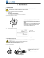
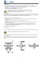
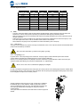
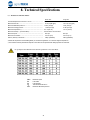
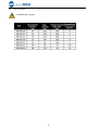
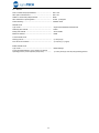
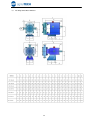
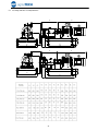
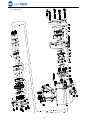
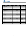
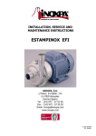
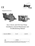
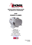
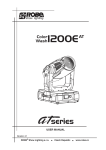
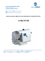
INSTALLATION, SERVICE AND MAINTENANCE INSTRUCTIONS LOBE PUMP 1. Safety 1.1. INSTRUCTION MANUAL This instruction manual contains information on the reception, installation, operation, fitting, stripping and maintenance for the TUR-TUL pump. The information given herein is based on the most up-to-date data available. SIGMATECH reserves the right to modify this instructions manual without having to give prior notice. 1.2. START-UP INSTRUCTIONS This instruction manual contains vital and useful information for properly operating the pump and for keeping it in good running condition. Not only should the safety instructions set forth in this chapter be carefully read before putting the pump into operation, but those concerned must also familiarise themselves with the operating features of the pump and strictly adhere to the instructions given herein. It is extremely important that these instructions be kept in a set place near the installation. 1.3. SAFETY 1.3.1. Warning signs Danger for people in general. Danger of injury caused by rotating parts of the equipment. Danger! Electricity. Danger! Caustic or corrosive agents. Danger! Suspended loads. Danger to the proper operating of the machine. Obligation to ensure safety at work. Use of safety goggles obligatory. 1.4. GENERAL SAFETY INSTRUCTIONS Please read the instruction manual carefully before installing and commissioning the pump. Should you have any doubts or queries, contact SIGMATECH 1.4.1. During the installation You must always bear in mind the Technical Specifications set forth in Chapter 8. Do not put the pump into operation before connecting it to the pipes. Do not put the pump into operation if the cover of the pump has not been fitted and the impeller fixed in the pump. Check that the motor specifications are correct, especially if there is a special risk of explosion due to the work conditions. During the installation procedure, all the electrical work must be carried out by duly authorised personnel. 1.4.2. During operation You must always bear in mind the Technical Specifications set forth in Chapter 8. The limit values that have been set must NEVER be exceeded. NEVER touch the pump or pipes whenever the pump is being used to decant hot liquids or during the cleaning procedure. 1 The pump has moving parts. Do not put your fingers into the pump when it is operating. NEVER work with the suction and the delivery valves shut off. NEVER directly sprinkle the electric motor with water. Standard motor protection is IP-55: dust and water sprinkling protection. 1.4.3. During maintenance You must always bear in mind the Technical Specifications set forth in Chapter 8. NEVER strip the pump down until the pipes have been drained. Remember that there will always be some liquid left in the pump casing (if it has not been fitted with a drain). Always remember that the liquid that has been pumped may be dangerous or subject to high temperatures. For situations of this type, please consult the prevailing regulations in the country in question. Do not leave loose parts on the floor. ALWAYS turn the power supply to the pump off before embarking on maintenance work. Take out the fuses and disconnect the wires from the motor terminals. All electrical work must be carried out by duly authorised personnel. 1.4.4. In accordance with the instructions Any failure to comply with the instructions could lead to a hazard for the operators, the atmospheric conditions of the room, and the machine, and it could lead to a loss to any right to make a claim for damages. Such non-compliance could bring with it the following risks: • Important operating failures of the machine / plant. • Failure to comply with specific maintenance and repair procedures. • Potential electrical, mechanical and chemical hazards. • Atmospheric conditions in the room could be hazardous due to the release of chemical substances. 1.4.5. Warranty We wish to point out that any warranty issued will be null and void and that we are entitled to an indemnity for any civil liability claim for products which might be filed by third parties if: • Operation and maintenance work has not been done following the corresponding instructions; the repairs have not been made by our personnel or have been made without our written authorization; • Modifications are made to our material without prior written authorization; • The parts or lubricants used are not original DONJOY parts/lubricants; • The material has been improperly used due to error or negligence or has not been used according to the indications and the intended purpose. • The parts of the pump have been damaged as a result of having been exposed to strong pressure as there was no pressure relief valve. The General Delivery Terms which you have already received are also applicable. No modification can be made to the machine without the prior consent of the manufacturer. For your safety, use spare parts and original accessories. from any and all responsibility. The use of other parts exempts the manufacturer Any change in operating conditions can only be done with the prior written consent of SIGMATECH In the event of doubt or should you require a fuller explanation on particular data (adjustment, assembly, disassembly...), please do not hesitate to contact us 2 2. Index 1. Safety 1.1. Instruction manual .......................................................................................................... 1 1.2. Start-up instructions ........................................................................................................ 1 1.3. Safety............................................................................................................................. 1 1.4. General safety instructions ............................................................................................... 1 2. Index 3. General Information 3.1. Description...................................................................................................................... 4 3.2. Operating principle .......................................................................................................... 4 3.3. Application ...................................................................................................................... 5 4. Installation 4.1. Pump reception ............................................................................................................... 6 4.2. Transport and storage ..................................................................................................... 6 4.3. Location...........................................................................................................................7 4.4. Coupling ..........................................................................................................................7 4.5. Pipes ...............................................................................................................................8 4.6. Presure relief valve ...........................................................................................................9 4.7. Electrical installation .........................................................................................................9 5. Start-up 5.1. Start-up .........................................................................................................................10 5.2. Pressure By-pass ............................................................................................................10 6. Operating Problems 7. Maintenance 7.1. General maintenance......................................................................................................13 7.2. Storage..........................................................................................................................13 7.3. Cleaning ........................................................................................................................14 7.4. Pump disassembly ..........................................................................................................15 7.5. Pump assembly ..............................................................................................................17 7.6. Lobe adjustment ............................................................................................................19 7.7. Mechanical seal assembly and disassembly ......................................................................20 8. Technical Specifications 8.1. Technical specifications...................................................................................................21 8.1.1 Frame of the particles............................................................................................. ......22 8.2. Materials ...................................................................................................................... 23 8.3. Lobe pump without motor dimension...............................................................................24 8.4. Lobe pump with motor assembly dimension ....................................................................25 8.5. Exploded view ................................................................................................................26 8.6. Spare parts ................................................................................................................27 3 3. General Information 3.1. DESCRIPTION The TUR-TUL lobe pumps made by SIGMATECH are part of our wide range of positive displacement rotary pumps for viscous liquids. The lobe pump has the following features: • • The TUR-TUL pump normal flow rate suitable for differential pressures of up to 12 bar. The TUR-TUL pump with wider lobes, delivers a higher flow rate, and is suitable for differential pressures of up to 7 bar. The TUR-TUL model has been specially developed to respond to all hygienic requirements in the food industry. As regards hygiene, reliability and sturdiness, the complete range of lobe pumps satisfies all requirements set by the aforesaid industry. Its modular design enables optimal part interchange between the different pumps. The lobe pumps are rotary displacement pumps. Owing to the contact between the internal parts, the pressure variations, etc. they make a louder noise than centrifugal pumps. This noise must be taken into consideration when installing these pumps. The TUR-TUL rotary lobe pumps by SIGMATECH have been approved by EHEDG and the American 3A Standards Authority. This equipment is suitable for use in food processing applications with strict hygienic requirements. 3.2. OPERATING PRINCIPLE The lobe pump is a positive displacement rotary pump. The left lobe is driven by the driving shaft. The right lobe is located on the driven shaft, and is driven via a helical gear. Both lobes rotate in synchronism without one touching the other. When the pump is running they displace a set volume of liquid. Figure below shows how a lobe pump operates. A: When the lobes rotate, the space on the suction side increases because one lobe moves away from the other, thus causing a partial vacuum that draws the liquid into the pumping chamber. B: Each lobe void is filled consecutively as the shafts rotate and the liquid is displaced towards the discharge side. The small clearances between the lobes and between the lobes and the walls of the pump body duly cause the spaces to be rather well closed. C: The pump body is completely full and the liquid leaks through the meshing of the lobes, knocking against the space walls so as to thus complete the pumping action. 3.3. APPLICATION The main advantage of the SIGMATECH TUR-TUL lobe pump is its capacity to pump a great variety of viscous liquids, from 1 mPa.s up to 100.000 mPa.s Furthermore, it is capable of pumping liquid products that require very careful handling and liquids that contain soft solids thus causing only a minimum degradation of same. 4 3.3.1. Field of application The range of application for each type of pump is limited. The pump was selected for a given set of pumping conditions when the order was placed. SIGMATECH shall not be liable for any damage resulting from the incompleteness of the information provided by the purchaser (nature of the fluid, rpm, etc.). 5 4. Installation 4.1. PUMP RECEIPTION SIGMATECH is not responsible for any deterioration of the material as a result of its transportation or unpacking. Visually check that the packing has not suffered any damage. The pump will be accompanied by the following documentation: • Dispatch notes. • Pump Instruction and Service Manual. • Drive Instruction and Service Manual (*). • (*) If the pump has been supplied with a drive from SIGMATECH Unpack the pump and check the following: • The pump suction and delivery connections, removing the remains of any packing material. • Check that the pump and the motor have not suffered any damage. • Should the pump not be in proper condition and/or does not have all the parts, the haulier must draw up a report as soon as possible with regard to the same. 4.1.1. Pump identification and marking Serial number Pump plate 4.2. TRANSPORT AND STORAGE Pumps and pumping units are often too heavy to be stored manually. Use an adequate means of transport. Use the points which are indicated in the drawing for lifting the pump. Only authorized personnel should transport the pump. Do not work or walk under heavy loads. Lift the pump as shown below: • • • 6 Always use two support points placed as far apart as possible. Secure the support so that it will not move. See chapter 8. Technical Specifications to consult dimensions and weights. 4.3. LOCATION • Position the pump as near as possible to the suction tank, and whenever possible below the level of the liquid. • Place the pump in such a way that there is enough space around it to provide access both to the same and to the motor. (See Chapter 8. Technical Specifications to consult dimensions and weights). • Place the pump on a level and flat surface. • The basement must be rigid, horizontal and against any vibration. Install the pump in such a way that it can be properly ventilated. If the pump is to be installed outside, it must be done so under cover. Its positioning must enable easy access for any inspection and maintenance operations that may need to be carried out. 4.3.1. Foundation Install the pump base so that the drive and pump are level and well supported. Therefore the pump unit should be installed on a base plate, or on a frame, both placed exactly level on the foundation. The foundation must be hard, level, flat, vibrations free... to prevent base distortion (to keep the alignment pump –drive guaranteed while commissioning). To install the pump unit on the foundation proceed as follows: • Make holes in the foundation to fit foundation bolts. This is unnecessary when expanding screws are used instead of foundation bolts. • Place base plate or frame with the aid of shims horizontally on the foundation. • Grout • When the grout has entirely hardened the pump unit can be placed on the base plate or the frame. Tighten the nuts on the foundation bolts carefully. • After unit is installed recheck alignment of pump and motor shaft and alignment of piping. Realign if necessary. • In the case of applications dealing with high temperatures the pump can be operated temporarily at its working temperature. Then recheck alignment pump - piping. For other foundations consult SIGMATECH 4.4. COUPLING If the pump is supplied with motor, the pump and motor shaft of complete units have been accurately pre-aligned in our factory. After installations of the pump unit, the pump and motor shaft should be re-aligned. Place a straight-edge (A) on top of the coupling: the straight should make contact with both halves of the coupling over their entire length. See figure. Repeat the check, but this time on both sides of the coupling near the shaft. For the sake of accuracy, this check should also be done using an outside caliper (B) at two diametrically opposite points on the outside surfaces of the two halves of the coupling. 7 Maximum alignment deviations: Outside diameter of the coupling [mm] 70 - 80 Vamin [mm] 2 Vamax [mm] 4 81 - 95 2 4 0,15 0,15 Vamax - Vamin [mm] 0,13 Vr. [mm] 0,13 96 - 110 2 4 0,18 0,18 111 - 130 2 4 0,21 0,21 131 - 140 2 4 0,24 0,24 141 - 160 2 6 0,27 0,27 161 - 180 2 6 0,3 0,3 181 - 200 2 6 0,34 0,34 201 - 225 2 6 0,38 0,38 4.5. PIPES • In general, suction and delivery pipes should be fitted in straight stretches, with the minimum amount of elbows and accessories, in order to reduce, as far as possible, any head load loss that might be produced by friction. • Make sure that the pump ports are well aligned with respect to the piping and that they are similar in diameter to that of the pipe connections. • Position the pump are near as possible to the suction tank, and whenever possible below the level of the liquid, or even lower with respect to the tank in order for the static suction head be at its maximum. • Place brackets for the piping as near as possible to the suction and delivery ports of the pump. 4.5.1. Shut-off valves The pump can be isolated for the purpose of carrying out maintenance work. To this end, shut-off valves should be fitted at the pump’s suction and delivery connections. These valves must ALWAYS be open whenever the pump is operating. 4.5.2. Self-priming process In general terms --if the self-priming process is followed-- the pump ought to contain sufficient liquid to fill the internal recesses and the void spaces thus enabling the pump to create a pressure difference. However, if low viscosity fluids are to be pumped, a foot valve of the same or greater diameter as that of the suction pipe should be installed; alternatively, the pump can be installed with a "U" shaped piping. The use of a foot valve is not recommended for pumping viscous liquids. In order to eliminate air and gases from the suction pipe, the counter-pressure on the discharge pipe should be reduced. When the self-priming process is used, the pump's start-up should be done by opening and emptying the discharge pipe which allows the air and gases to escape at a low counter-pressure. Another possibility involves long pipes or when a check valve is installed in the discharge pipe; it is also possible to install a by-pass with a shut-off valve on the discharge side of the pump. This valve shall be opened in the case of priming and will allow air and gases to escape at a minimum counter-pressure. The by-pass should not lead back to the intake orifice but to the supply tank instead. 8 4.6. PRESURE RELIEF VALVE The positive displacement lobe pumps must be protected from excess pressure when they are operating. Consequently, all the TUR-TUL pumps can be fitted with a stainless steel pressure relief valve or a pressure by-pass 4.6.1. Protection This valve protects the pump and prevents excessively high pressure arising in the circuit. It reduces the differential pressure (∆p) between suction and discharge, but not the maximum pressure within the plant. Do not use the pressure relief valve to protect the system from excess pressure. It is designed to protect the pump only as it is not a safety outlet. 4.6.2. Operation principle The by-pass valve prevents excess pressure arising inside the pump. For example, when the pump's discharge port is clogged and the liquid cannot be pumped out, too high a pressure can cause serious damage to some of the pump's parts. The pressure relief valve opens a passage from the pump's discharge side to its suction side: an escape route, redirecting the flow again to the suction side whenever specifically high pressure levels are reached. If the pressure relief valve operates, this will mean that the equipment is not working properly. The pump should be disconnected immediately. Identify and solve the problem before re-starting the pump. Remember that the pressure relief valve is not able to be used to regulate the flow rate. The pressure relief valve can be adjusted to any determined pressure, according to the type of pump being used. 4.7. ELECTRICAL INSTALLATION Leave the connecting of the electrical motors to qualified personnel. Take the necessary measures to prevent any breakdowns in the connections and wires. The electrical equipment, the terminals and the components of the control systems may still carry an electric charge even when disconnected. Contact with them may put the safety of operators at risk, or cause irreparable damage to the material. Before manoeuvring the pump, make sure that the electric box is switched off. • Connect the motor in accordance with the instructions supplied by the manufacturer of the same. • Check the direction of the rotation (see the signalling label on the pump). • Start the pump motor briefly. Make sure the pumping direction is the right one. If the pump operates in the wrong direction it may cause severe damage. Check ALWAYS the direction of the motor’s rotation with liquid inside the pump. 9 5. Start-up Before putting the pump into operation read carefully the instructions on installation given in Chapter 4. Installation. 5.1. START-UP Read Chapter 8. Technical Specifications carefully. SIGMATECH will not assume responsibility for any improper or incorrect use of the equipment. Do not touch the pump or the piping while it is pumping products at a high temperature. 5.1.1. • • • Checks to be carried out before putting the pump into operation Completely open the pipes’ suction and delivery shut-off valves. Check oil level of the pump. Add correct grade of oil as necessary to maintain level in center of oil sight glass (In the case of first start-up: pumps are shipped with oil in the gearbox). If the liquid fails to flow toward the pump, fill it with the liquid to be pumped. The pump must NEVER rotate without fluid inside it. • • • 5.1.2. Check that the power supply matches the rating indicated on the motor plate. Check that the direction of rotation of motor is the right one. If the pump has a double or a flushed mechanical seal, mount the auxiliary connection corresponding to the values indicated in Chapter 8, Technical Specification. Checks to be carried out on putting the pump into operation • Check to make sure that the pump is not making any strange noises. • Check to see if the absolute inlet pressure is sufficient, in order to avoid cavitations in the pump. Consult the curve for the minimum required pressure above the steam pressure (NPIPr). Monitor the delivery pressure. Check that there are no leaks in the sealed areas. • • A shut-off valve should not be used in the suction pipe to regulate the flow rate. It must be completely open during operation. Monitor motor consumption in order to avoid a circuit overload. Reduce flow and motor power consumption by reducing motor speed. 5.2. PRESSURE BY-PASS The valve's opening pressure depends on the fluid to be pumped, its viscosity, its rpm ..., and so before starting-up the pump, the operator ought to adjust the pressure relief valve's opening pressure. When checking the relief valve also make sure the pump's pressure will NEVER exceed the pressure setting + 2 bar. 10 When the pressure relief valve is equipped this valve has been adjusted to the pump’s maximum operating pressure. Correct operating pressure has to be adjusted by end user. When the relief valve does not work properly, the pump must be taken out of service immediately. The valve must be inspected by an SIGMATECH service technician. Example of Pressure Relief Valve installation 11 6. Operating Problems The table given below provides solutions to problems that might arise during pump operation. With respect to the same, it is assumed that the pump has been properly installed and has been correctly selected for the application in question. Should there be a need for technical service please contact SIGMATECH Operating problems Motor Overload Insufficient discharge flow rate No pressure on the discharge side Irregular discharge flow rate/pressure Noise and vibrations The pump gets clogged Overheating of pump Abnormal wear Leak through mechanical seal Probable causes 1 2 Wrong rotation direction Insufficient NPIP 3 4 5 6 7 8 Pump not purged Cavitation The pump sucks in air Suction pipe clogged Wrong setting of pressure relief valve Discharge pressure too high 9 Viscosity of the liquid is too high 10 Viscosity of liquid too low. 11 12 13 14 15 16 17 18 Temperature of liquid too high. Pump speed too high The lobes are worn Pump speed too low Product very abrasive Worn bearings Worn or damaged mechanical seal O-rings and gaskets are not the right ones for the liquid Worn gears Insufficient lubricating oil level Unsuitable lubricating oil The lobes rub 19 20 21 22 23 24 25 26 Coupling misalignment Tension on the pipelines Foreign bodies in the liquid Pump and / or electric motor not fixed on foundation Probable causes 8, 9, 12, 16, 20, 21, 22, 23, 24, 26. 2, 4, 5, 7, 8, 9, 10, 11, 13, 14. 1, 2, 3, 6, 7. 2, 4, 5, 6, 9, 12. 2, 4, 5, 6, 7, 8, 9, 11, 12, 13, 16, 19, 20, 21, 22, 23, 24, 25, 26. 8, 9, 11, 16, 19, 20, 21, 22, 24, 25, 26. 7, 8, 9, 11, 12, 16, 20, 21, 22, 23, 24, 26. 4, 5, 11, 15, 16, 19, 24, 25. 17, 18, 27. Solutions Invert the rotation direction Increase available NPIP: - Rise the suction tank - Lower the pump - Reduce the speed - Increase the diameter of the suction pipe - Shorten and simplify the suction piping. Purge or fill Increase suction pressure ( see 2) Check suction pipe and all its connections. Check the suction pipe and filter(s), if any. Check the pressure relief valve's setting If necessary, reduce the loss of head by increasing the diameter of the discharge pipe - Reduce the pump speed - Reduce the viscosity, for example, by heating the liquid. - Increase the pump speed - Increase the viscosity, for example, by cooling the liquid. Reduce the temperature by cooling the liquid. Reduce the pump speed Replace the lobes Increase the pump speed Fit hardened lobe hubs Replace the bearings, check the pump Replace the seal Fit the proper O-ring and gaskets; check with the supplier. Replace and readjust the gears Fill up with oil Use an appropriate oil - Reduce the temperature - Reduce the discharge pressure - Adjust the clearance Align the coupling Connect the pipelines to the pump free of tensions Insert a filter in the suction pipe Tighten, check that the piping has been connected stressfree and align the coupling If the problem persists, use of the pump must cease immediately. Contact 12 SIGMATECH or its representative. 7. Maintenance 7.1. GENERAL MAINTENANCE This pump, as with any other machine, needs to be maintained. The instructions contained in this manual deal with the identification and replacement of the spare parts. These instructions have been drawn up by maintenance staff and are destined for those people who are responsible for supplying spare parts. Read carefully Chapter 8. Technical specifications. All the parts or materials that are changed must be duly eliminated / recycled in accordance with the prevailing directives in each area. ALWAYS disconnect the pump before starting out on any maintenance work. 7.1.1. Check the mechanical seal Periodically check that there are no leaks in the shaft area. Should there be any leaks in the mechanical seal area, replace the same pursuant to the instructions given in the Pump Disassembly and Assembly section. 7.1.2. Dry thread torque Dry thread torque [N.m.] Material M5 M6 M8 M10 M12 M14 M16 M18 M20 8.8 6 10 25 49 86 135 210 290 410 A2 5 9 21 42 74 112 160 210 300 7.1.3. Oiling The bearings are oiled by immersion in an oil bath. The pumps are supplied with oil. • Regularly check the oil level, for example, weekly or every 150 operating hours. • The first oil change must be carried out after 150 hours of operation. • Afterwards, it can be changed every 2500 operating hours or at least once a year when operating under normal conditions. When change the oil: the oil sump must be filled up to the level in the middle of the peephole. Do not pour too much oil into the sump. Leave the pump switched off for a while and then re-check the oil level; if necessary, add a little oil. Pump type and Oils in the gear case(l.). PUMP TYPE TUR-TUL 20,23,25 Quantity of oil in the gear case (l.) 0,5 TUR-TUL 30,35 0,75 TUR-TUL 55,60 0,75 7.2. STORAGE Before being stored the pump must be completely emptied of liquids. Avoid, as far as possible, the exposure of the parts to excessively damp atmospheres. 13 7.3. CLEANING 7.3.1. Manual cleaning The use of aggressive cleaning products such as caustic soda and nitric acid may give rise to skin burns. Use rubber gloves during the cleaning process. Always use protective goggles. 7.3.2. Automatic CIP (cleaning-in-place) If the pump is installed in a system fitted with a CIP process, there will be no need for stripping. The recommended minimum liquid speed for an effective process of cleaning is 1,8 m/s (minimum Re > 100 000 at 1,0~2,5 bar). If it is not fitted with an automatic cleaning process, strip the pump pursuant to the instructions given in the section entitled Stripping and Assembly of the pump. Cleaning solutions for CIP processes. Only use clear water (chloride free) to mix with the cleaning agents: a) Alkaline solution: 1% in weight of caustic soda (NaOH) to 70ºC (150ºF) 1 kg NaOH + 100 l. water = cleaning solution or 2.2 l. NaOH to 33% + 100 l. of water = cleaning solution b) Acid solution: 0.5% in weight of nitric acid (HNO3) to 70ºC (150ºF) 0.7 litres HNO3 to 53% + 100 l. water = cleaning solution Monitor the concentration of cleaning solutions; it could give rise to the deterioration of the pump sealing gaskets. These solutions are given as examples and should be validated before use on an application. In order to remove any remains of cleaning products, ALWAYS rinse the element in question with clean water after completing the cleaning process. 7.3.3. Automatic SIP (sterilization-in-place) The process of sterilization with steam is applied to all the equipment including the pump. Do NOT start the pump during the process of sterilization with steam. The parts/materials suffer no damage if the indications specified in this manual are observed. No cold liquid can enter the pump till the temperature of the pump is lower than 60°C (140°F). A flow by-pass is recommended to be used in order to assure the flow of sterile product after the pump. Maximum conditions during the SIP process with steam or overheated water a) b) c) d) Max. temperature: Max. time: Cooling: Materials: 140°C (284°F) 30 min Sterile air or inert gas EPDM / PTFE (recommended) 14 7.4. PUMP DISASSEMBLY The assembly and disassembly of the pumps should only be done by qualified personnel. Make sure that the personnel read carefully this instruction manual and, in particular, those instructions which refer to the work they will perform. Incorrect assembly or disassembly may cause damage in the pump's operation and lead to high repair costs and a long period of down-time. SIGMATECH is not responsible for accidents or damages caused by a failure to comply with the instructions in this manual. Preparations Provide for a clean working environment as some parts, including the mechanical seal, require very careful handling and others have close tolerances. Check that the parts which are used are not damaged during transport. When doing this, you need to inspect the adjustment edge, the butted faces, the tight fit, burrs, etc. After each disassembly, carefully clean the parts and check for any damage. Replace all damaged parts. Tools Use the proper tools for assembly and disassembly operations. Use them correctly. Cleaning Before disassembling the pump, clean it on the outside and on the inside. NEVER clean the pump by hand when it is running 7.4.1. Pump cover disassembly CAUTION! Liquid may spill from the rotor case when removing the pump cover. 7.4.2. Close the suction and delivery valves. Remove the cap nuts (01,02,03). Check that the seal (06) is in good condition. Loosen the lobe screws (08) using a spanner, remove seal (09) and check. These screws have a right-hand thread. In order to prevent the Lobe disassembly lobes from turning simultaneously, blocks of wood or plastic can be placed between the lobes. Remove both lobes (10). If necessary, use a tool to assist for this purpose. Check that the O-ring (11) is in good condition. 15 7.4.3. Disassembly of Mechanical Seals As a result of the pump design, it is not necessary to disassemble the rotor case (25) in order to assemble/disassemble the mechanical seals. Mechanical seal is directly mounted to the rotor case. 7.4.4. 7.4.5. 7.4.6. Rotor Case Disassembly • Loosen and remove the nuts and bolts(21,22,23,24) using a spanner. • Remove the rotor case (12) using Nylon hammer if necessary. Gear Case Rear Cover Disassembly • Loosen and remove the bolts(43) in the rear cover of the gear case using a spanner. • Remove rear cover, take off the washer carefully and check. • Loosen the three bolts(39) in the gear case using a hex.spanner, remove the gear cap(38), take off tighten ring. • Remove the two gears (36). Shaft Assembly Removal • Loosen and remove the bolts(18) in the sealing cap using a hex.spanner, • Remove the shaft assembly from the gear case(05). Due to the tightness of the bearings cover, a Nylon hammer must be used. Lightly tap the rear part of the driveshaft (32) and (31) till take off the two driveshaft . • Remove the oil sealing bottom cover(19) from the driveshaft(32) and (31), remove the oil sealing(20) and check, if there are any defects, find a replacement before reassembling the pump. Note: Each driveshaft must be taken off separately. 16 7.5. PUMP ASSEMBLY 7.5.1. Shaft Assembly • Check that the oil sealing (20) has not been damaged and attach with a little grease or oil in the correct position of the bottom cover (19). • Along the two driveshaft holes of the gear case, use a Nylon hammer use a Nylon hammer and lightly tap the shafts (32 and 31) until the bearings cover is well fixed to the gear case. Note: Each driveshaft must be assembled into the gear case separately. 7.5.2. • Place gear(36) on the driveshaft(32,31), put tightening ring(37) into gear, along the driveshaft put the gear bottom cover(38) into gear and aim at the bolt hole, assemble the bolt(39) into the gear using a hex.spanner. After finishing the assembly of the gear, turn the driveshaft several circles to make sure there is no friction and lock. • Check seal(40) and oil sealing(42), make a replacement if necessary • Fix the oil sealing(42) into the rear cover(41) of the gear case. • Grease the seal, and place it in the gear case(25) carefully and aim at the bolt hole • Along the driveshaft(32), put the oil sealing hole of the rear cover(41) into the gear case, and aim at the bolt hole. • • Remove the oil plug (26) located at the top of the gear case (25). Fill the gear case (25) with lubricant oil up to the middle level of the sight-glass (27). Filling with Lubricant Oil See 7.1.3 Oiling for the type and quantity of oil to use. 7.5.3. Rotor Case Assembly CAUTION! When reassembling the rotor case, pay attention to the position of the centring pins. • Grease O-ring(13) and fix it into mechanical seal stationary ring, put it in the sealing step in the back of the rotor case, insert the stationary ring pin into the stationary ring hole. • Mount the tightening cover(17) in the driveshaft(32,31), then place the mechanical seal rotary ring into the driveshaft(32,31). • Insert the fixing pin of the rotor case into the gear case(25), and then assemble the rotor case into the gear case, tighten the bolt(21,22,23,24) using a spanner. 17 7.5.4. Lobe assembly ALWAYS check the clearance between the lobes and lobes and rotor case before finishing assembly. See 7.6.1 Clearance and tolerance table 7.5.5. • Fit new O-rings (09) to the lobe screws (08), replace a new o-ring(11) in the driveshaft • Push the lobe(10) into the driveshaft (32 and 31) slightly. Place the lobe bolt (08) onto the driveshaft. • Assembly is exactly the same for all lobe types. • Check that the O-ring (06) is in good condition or, if necessary, replace it with a new one. Place it in the pump rotor case (05) . Pump cover assembly • • Place the pump cover (06) onto the rotor case (12) and tighten the bolt and blind nuts (01,02,03,04). • See chapter 5.1.1 Checks to be carried out before putting the pump into operation 18 7.6. LOBE ADJUSTMENT 7.6.1. Clearance and tolerance table (mm) TUR-TUL 20 23 25 TUR-TUL 30 35 TUR-TUL 55 60 A B C E 0,20 ±0,05 0,25 ±0,05 0,30 ±0,05 0,20 ±0,03 0,25 ±0,03 0,30 ±0,05 0,40 ±0,05 0,45 ±0,05 0,40 ±0,05 1,3 ±0,03 1,3 ±0,03 1,3 ±0,05 A = axial clearance between the lobe and the cover. B = axial clearance between the lobe and the rear of the rotor case. C = radial clearance between the lobes. E = radial clearance between the lobe and the rotor case on the suction side. 7.6.2. Synchronising the lobes • In order to enable the gear(36) to be tightened, mount it in the driveshaft(32,31), and put the tighten ring(37) into the iside of the gear, then push the bottom cover(38) into the inside of the gear, aim at the bolt hole, and tighten it with bolt. Note: The gear and lobes run synchronously, and the lobes will not touch each other. 19 7.7. MECHANICAL SEAL ASSEMBLY AND DISASSEMBLY 7.7.1. Single Mechanical Seal Mechanical seals are fragile parts. Take care when handling them. Do not use any screwdriver or similar tool to pull out the parts. • • • Clean all the components of the mechanical seal before placing them. Check that the working surfaces are not damaged. SIGMATECH recommends replacing the entire mechanical seal if one of the working surfaces has a defect. Replace the O-rings during assembly. Disassembly • • Remove the stationary fixed pin(04) from the rotor case, take off the stationary cover. Please proceed carefully. Loosen the fixed bolt(09) in the driveshaft, remove the rotary ring(05) and fixed cover(10) from the driveshaft. Assembly • • Lubricate all the O-rings of the mechanical seal with soapy water or oil compatible with the material of the seals, pumped liquid and application. Mount the driveshaft tightening cover(11) in the driveshaft, mount the rotary sealing parts(05,06,07,08,09,10) in the driveshaft. • Fit the stationary part (01,02,03) into the rotor case, and aim at the bore, ensuring that the fixed pin(04) engage with the slot edge of stationary ring. • Assemble the rotor case and gear case(see paragraph 7.5.3), push the rotary parts(05) several times, adjust the fixed bolt(09) using the hex.spanner,till the rotary ring and stationary ring reach to a perfect position. • Clean the working surfaces with solvent. • Reassemble the lobe rotor according to 7.5.4 Lobe assembly 20 8. Technical Specifications 8.1. TECHNICAL SPECIFICATIONS Short rotor Long rotor Theoretical displacement volume x 100 rev. ............................. 217 litres Maximum flow rate ................................................................. 78 m3/h (586 gpm) 321 litres 115 m3/h (700 gpm) Maximum differential pressure................................................. 7 bar (102 psi) 12 bar (174 psi) Maximum working pressure..................................................... Maximum temperature (1) ....................................................... 16 bar (232 psi) 110 °C (230 ºF) 16 bar (232 psi) 110 °C (230 ºF) Maximum viscosity (2) (recommended)..................................... 100.000 mPa.s 100.000 mPa.s Maximum speed ..................................................................... 950 rpm 950 rpm Maximum connections............................................................. 100 mm (4 in) Suction / delivery connections ................................................. Clamp (standard) 150 mm (6 in) Clamp (standard) (1) Maximum (2) The temperature due to EPDM gaskets, for continuous application. To consult for higher temperatures maximum viscosity allowed will depend on the nature of the liquid and the sliding speed of the seal faces. Use special protection when the noise level in the operation area exceeds 95 dB(A). Nmax. B D Q Pmax. 1 1 th Maximum speed Lobe width Lobe diameter Theoretical flowrate at Nmax. Maximum differential pressure 21 8.1.1. Frame of the particles ¡ WARNING! Only soft particles. 22 8.2. Materials Parts in contact with pumped material...................................... Other parts in stainless steel.................................................... Gaskets in contact with pumped material ................................. Other materials for optional gaskets......................................... Surface finishing ..................................................................... AISI 316L AISI 304 EPDM Consult yoursupplier Standard finish Mechanical seal Type of seal ........................................................................... Stationary parts material ........................................................ Rotary parts material .............................................................. Elastomers material ................................................................ Single internal balanced mechanical seal Carbon Silicon carbide EPDM Cooled mechanical seal Working pressure.................................................................... Flow rate of the circulation ...................................................... 0,5 bar (73 psi) 2,5-5 l/min (0,7-1,3 gpm) Double mechanical seal Type of seal ........................................................................... Due to the balanced design, no over pressure is required Operating pressure (if it is required by the process) ................. 23 Balanced design 1,5-2 bar (22-29 psi) over the pump operating pressure 8.3. Lobe Pump without Motor Dimension 24 Lobe Pump with Motor Assembly Dimension L2 C4 C3 C1 C2 L1 E1 K1 N1 F1 N2 M1 L2 C2 L1 C4 C3 C1 8.4. E1 F1 K1 N1 M1 25 N2 Exploded view 8.5. 31 32 33 34 33 35 36 37 38 39 42 17 26 8.6. Spare parts Pos. Part Name Material Qty. Pos. Part Name Material Qty. A2-70 6 22 Spring gasket 304 4 21 Cap nut 304 4 43 Bolt 20 Oil sealing NBR 2 42 Oil sealing NBR 1 19 Bearing cover 45# 2 41 Gear case rear cover 45# 1 18 Hex.bolt A2-70 6 40 Gear case gasket 17 Tightening cover 304 2 39 Hex.bolt 16 Mechanical seal rotary parts 2 38 15 Column pin 6 14 Mechanical seal stationary parts 13 O ring 12 Rotor case 11 O ring 10 Lobe(rotor) 09 O ring 08 Lobe nut 07 Column pin 06 O ring 05 Front cover 04 Bolt 03 1 A2-70 6 Gear cover 45# 2 37 Gear tightening ring 45# 2 2 36 Gear 2 35 Tightening nut 1 34 Bearing fix position cover 2 2 33 Bearing 4 2 32 Long drive shaft 304 1 2 31 Short drive shaft 304 1 2 30 Jam 304 1 304 2 29 Hex.bolt A2-70 2 NBR 1 28 Base support cast iron 1 304/316L 1 27 Oil sight glass A2-70 4 26 Oil plug 304 Flat gasket 304 4 25 Gear case cast iron 1 02 Spring gasket 304 4 24 Bolt A2-70 4 01 Cap nut 304 4 23 Flat gasket 304 4 304 NBR 304/316L NBR 304/316L NBR 304/316L 27 2 45# 2 1 1