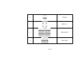
1
User’s manual for MPEG4 DVR
Model QSNDVR9M and QSNDVR16M
*This manual is for MPEG4 QSNDVR9M 9-channel and QSNDVR16M 16-channel digital video recorder
And uses the 16-channel digital video recorder as example.
Before operation, we strongly advise that you read the user manual and keep it available for future use.
This manual is an operational guide, we reserve the right to correct typographical errors or inconsistencies with future versions,
software upgrades and product improvements. These changes will be made without any special or advance notification.
Rev 101007
Page 1
Table of Contents
Digital Video Recorder (DVR) Introduction ..................................................................................................... 4
1.1 Product introduction .......................................................................................................................... 4
1.2 Features of this DVR .......................................................................................................................... 4
Installation Notice ......................................................................................................................................... 7
2.1 Checking the Contents………………................................................................................................. 7
2.2 Installing the HDD ........................................................................................................................... 7
2.2.1 Install reminder...................................................................................................................... 7
2.2.2 Install tool ............................................................................................................................... 8
2.2.3 Install process ........................................................................................................................ 8
2.3 Back panel and interface terminals ................................................................................................. 16
2.3.1 Back panel of 16-channel DVR ............................................................................................. 16
2.3.2 Back panel of 9-channel DVR ............................................................................................... 20
2.4 Front panel and interface terminals ................................................................................................. 21
2.5 Remote control description............................................................................................................... 24
2.6 Alarm cable connection ................................................................................................................... 29
Basic operation guide ................................................................................................................................... 30
3.1 How to start the DVR....................................................................................................................... 30
3.2 Login and setup the system ............................................................................................................ 32
Page 2
3.2.1 SETUP-SYSTEM .................................................................................................................. 34
3.2.2 SETUP-LIVE ......................................................................................................................... 39
3.2.3 SETUP-REC ......................................................................................................................... 42
3.2.4 SETUP-STORAGE ............................................................................................................... 50
3.2.5 SETUP-NETWORK............................................................................................................... 52
3.2.5.1 MONITORING FROM COMPUTER ON SAME ROUTER................................................. 53
3.2.5.2 MONITORING FROM A REMOTE COMPUTER............................................................... 54
3.2.5.3 PLAYBACK RECORDED FILE.......................................................................................... 56
3.2.6 SETUP-SENSOR/ALARM .................................................................................................... 57
3.2.7 SETUP-AUDIO...................................................................................................................... 61
3.3 Function ................................................................................................................................... 62
3.3.1 STATUS ................................................................................................................................ 62
3.3.2 AUDIO ................................................................................................................................... 63
3.3.3 BACKUP & VIEW BACKUP ................................................................................................. 64
3.3.4 PAN/TILT ............................................................................................................................... 71
3.3.5 ZOOM/FOCUS ...................................................................................................................... 71
3.3.6 SEQUENCE .......................................................................................................................... 72
3.3.7 LOG LIST .............................................................................................................................. 73
3.4 Search record.......................................................................................................................... 75
3.5 SPOT ........................................................................................................................................ 81
Appendix A Main Standard & Parameter chart.................................................................................... 83
Appendix B Recording capability ........................................................................................................ 87
Appendix C The meaning of some abbreviations .................................................................................88
Page 3
Digital Video Recorder (DVR) Introduction
1.1 Product introduction
This DVR is designed specially for CCTV system. It uses an embedded processor and embedded
operating system working with the high-powered code and decode chip. In addition, it uses advanced
IT technology to make the system more stable, such as the audio code and decode technology, large
capacity hard disks, complying with the TCP/IP protocol SoC, etc…
It is a stand alone unit, but also works through the internet to allow the customer to have remote
Surveillance. It is ideal for middle-risk to high risk site surveillance. Due to its good performance it is used in
the Banking Industry, Telecommunication Industry, Electric Power Departments, Legal Systems, Factories,
Wherehouses, Cities, etc…
1.2 Features of this DVR
General
Video output: CVBS, S-VIDEO, VGA and SPOT monitor
Triplex operation: view/record/playback/remote operation at the same time
Various recording resolutions, D1, Half D1 and CIF
Supports channel security by hiding live display
Display the local record state and the basic information
Remote control equipped
Support two level password control: administrator and common user
Operation log recording and searching
Video system (PAL or NTSC) can be detected automatically and selected manually
Recording list can be deleted one by one or all and locked to protect important records
Support water mark technology
Page 4
Format
Standard MPEG-4 compression format
Storage
Supports up to four IDE Hard Drives simultaneously (Or three IDE HDDs and one IDE DVD-RW/CD-RW)
Backup
Auto-play software automatically packed in backup files, and Auto-water-mark check in backup files to
assure files’ authenticity
Support backup via USB 2.0 to USB flash memory, or CDRW, DVD-RW to CD-R/DVD-R respectively
Support remote backup by “Net Client” through LAN or internet
Record and playback
Record modes: Manual, Sensor detection, Timer, Motion detection and Continuous
Support HDD recycle (automatically overwrites older files)
Up to 16CH playback, fast forward 2X 4X 8X 16 32X 64X and 128X and slow forward modes;
play the record frame by frame; jog shuffle to forward/backward function, which is including frame
rate adjusting
Support remote playback in “Net Client” through LAN or internet
Three record search modes: time search, event search, file search
Page 5
Alarm
9/16 alarm inputs and 4 alarm outputs, TTL alarm output
PTZ control
Supports decoder which communicates with RS485
Supports speed dome
Supports PTZ through network
Communication port
RS 485 equipped
Network
Supports TCP/IP protocol
Supports wide bandwidth network through modem (PPPOE)
Supports static IP and dynamic IP (DHCP)
Real time preview/playback/monitoring with audio signal through network
Supports control PTZ camera through the network
Support IE browser, for remote view (automatically download active-x )
Page 6
Installation Notice
Attention: Before connecting to other equipment, please make sure the device is powered off.
Do not hot plug in!
2.1 Checking the contents
Check the contents when you receive the unit, to make sure you have all the parts. Normally it will
contain: a remote control, a power cable, a CD-Rom with “Net Client” software, screws for installing HDDs
2.2 Installing the Hard Drive
2.2.1 Install reminder
Please confirm the size of HDDs needed and choose suitable ones to install. If the original DVR does not
have HDDs, it is advisable to have professionals install/uninstall the drives.
Page 7
2.2.2 Install tool
One Phillips screwdriver
2.2.3 Install process
Open the DVR using screwdriver
Set one HDD as master and the other as slave if two HDDs are connected to one ATA interface!!!
Attention: Hard Drives connected to the same parallel cable can not be set as master+master or
slave+slave, they must be master+slave!!!
HDD setup: Using a Maxtor Hard Drive (DiamondMax Plus 8 ATA/133 40GB) as example.
Read the jumper diagram on the rear of HDD
No jumper=DS(SLAVE)
Page 8
Jumper area
The picture blow is the IDE connection/Power connection section of the HDD.
Jumper area
Jumper according to the diagram above
SLAVE
MASTER
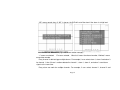
The sequence of read/write data from HDD
The ATA interface which is near the motherboard center is the secondary interface, the next ATA
interface which is near the motherboard edge is the primary interface. The sketch is in the following.
The HDD names are shown in the DVR system as HDD A/B/C/D. The master HDD connected to
Page 9
Primary ATA interface is HDD A, the slave is HDD B. The master HDD connected to secondary ATA interface
is HDD C, the slave is HDD D.
The record sequence is: HDD A→HDD B→HDD C→HDD D
Overwrite sequence: The sequence is irrespective of HDD. The DVR overwrites HDD from the oldest record
file when HDD is full.
Motherboard
Operation
Put the HDD into the HDD fixation rack. If the user wants to install more than two HDD, please
install the HDD into the bottom rack first.
Attach the HDD by two screws on both sides
Connect the HDD cable. There are three interfaces on cable and each of them can be connected with
the master HDD or the slave HDD, motherboard. (There are 39 pins in two rows, 20 pins are in one row and
Page 10
19 pins are in the other row). Make sure pins are plugged into interface correctly.
Connect the power supply to HDD
Sketch map of installation
Close the device cover and lock it with screws
Attention: Please format the HDD before using.
If the user wants to connect the CD/DVD driver to the ATA interface, please choose
the secondary interface, that is near the center of the motherboard. Furthermore, the CD/DVD
driver must be set as master, and the HDD which is connected to same ATA interface
with the CD-RW/DVD-RW must be set as slave.
Any CD/DVD drive connected to DVR must be set as master, including USB CD/DVD
drive and IDE CD/DVD drive.
The CD/DVD drive connected to ATA interface can be viewed in the STATUS or STORAGE
menu of DVR, the CD/DVD drive connected to USB interface can not be viewed in the menu of DVR.
The CD/DVD driver is optional, depending on the user. If user connects CD/DVD driver to
ATA interface, the max number of HDD that connects to ATA interface is three.
Page 11
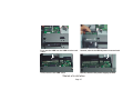
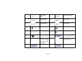
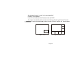
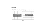
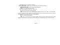
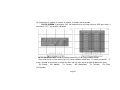
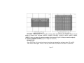
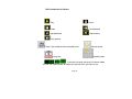
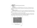
1
2
Fir st, put the HDD into the HDD fixation rack
sides
Second, attach the HDD by tw o screw s on both
4
3
Third, connect the HDD cable
Fourth, connect the pow er supply to HDD
Sketch of installation
Page 15
x
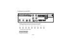
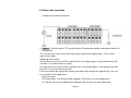
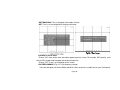
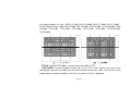
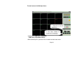
2.3 Back panel and interface terminals
Attention: The real connections on the back panel might be slightly
different from the sketch below.
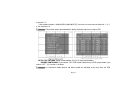
2.3.1 Back panel of 16-channel DVR
CAM1
CAM9
CAM2
CAM10
CAM3
CAM11
CAM4
CAM5
CAM 12 CAM13
CAM6
CAM1 4
CAM7
CAM8
CAM15 CAM16
AUDIO IN 1 AUDIO IN 2
1
2
ALARM OUT
ALARM IN
1 2 3 4
3 4 5 6 7 8
AUDIO IN 3 AUDIO IN 4
-
GN D
9 10 11 12 13 14 15 16 CO M +
RS-48 5
SPOT OUT
VIDEO OUT
S VIDEO
AUDIO OUT
LAN
USB
VGA
RS-2 32
Back panel of 16-channel DVR
Num
Icon
Description
Page 16
1
Video input 1-16
2
Spot output
3
Video output
4
S video output
5
Audio output
Page 17
6
LAN port
7
Audio in 1-4
8
Alarm input1-16
9
Alarm output
Page 18
10
Fan vent
11
Power plug
12
USB port
13
VGA port
14
RS 232 port
15
Null
RS485 port
Page 19
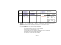
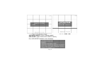
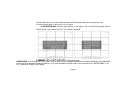
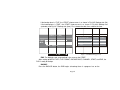
2.3.2 Back panel of 9-channel DVR
CA M 1
CAM 3
CAM 2
SPO T OUT
CA M 5
CA M 4
VI DEO OUT
AUD IO IN 1 AUDIO IN 2
CAM 9
CAM 7
CA M 6
S VID EO
CAM 8
1
2
ALA RM IN
3 4 5 6 7 8 9
ALARM OUT
1 2 3 4
AUD IO IN 3 AUDIO IN 4
AUD IO OU T
COM
+
-
GND
RS- 4 85
LAN
USB
VG A
Back panel of 9-channel DVR
The difference between 9-channel and 16-channel is the 9-channel
has 9 video in and 9 alarm inputs, 16 channel has 16 of each.
9 channel video and alarm inputs
Page 20
RS- 2 32
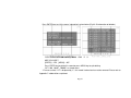
2.4 Front panel and interface terminals
Attention: The actual buttons on the front panel please might be slightly difference from
this sketch.
1
14
11
1
2
3
P T
4
5
6
Z/F
7
8
9
AUDIO
MODE
B ACKUP
0
Po wer
4
Number Icon
Number
1
Page 21
LED
12
Icon
5
27
26
16
23
7
REC
17
MENU
2
28
15
13
6
FUNCTION
8
Description
9
SEAR CH
PLAY
10
Number Icon
USB
18
21
19
22
20
25
24
Description
Description
CD-RW/DVD-RW
Number
2
3
Number button
4
Sequence button
5
Display
mode
shift button
6
Pan/Tilt control
Page 21
Icon
STO P
FF
REV
INFO R
Description
Power button
7
Zoom/Focus
control
8
Audio on/off button
9
Backup button
10
Menu button
11
Function button
12
Status button
13
Move Left
14
Move Up
15
Enter button
16
Move Right
17
Move down
18
Record button
19
Shuttle: to control 20
the DVR to play
the record frame
Shuttle: to control the
playback speed
by frame.
21
Search button
22
Page 22
Play button
23
Fast Reverse
25
24
Fast forward
26
Remote
receiver
28
LED indicator lights, for
power,
HDD
and
backup, network status,
playback status and
record
status
Stop
27
controller
respectively.
Attention:
The CD-RW/DVD-RW is optional. If a CD-RW/DVD-RW is connected to the ATA
interface, the maximum number of HDDs you can attach to the ATA interface is three.
LED indicator lights:
The first light is on when the DVR is powered on;
The second light flickers when HDD is written or read;
The third light is on when backup is in DVR;
The fourth light is on when a computer connects with the DVR via network;
The fifth light is on when the DVR is playing back;
The sixth light is on when the DVR is recording.
Page 23
2.5 Remote control description
Put the Battery into the Remote control:
Open the battery cover of Remote control
Put in two AAA batteries and make sure that they are inserted correctly
Replace the battery cover
The top view of remoter control:
The button description:
Number Icon
1
.
Description
Record button: Press this button to start recording if the DVR is not
recording. Press this button to stop recording if the DVR is recording.
Page 24
2
Backup button: Press this button, the DVR enters the backup menu
(Fig 3.3.7 USB backup). The details will be given in Chapter 3.3.3:
BACKUP
3
Information button: Press this button to display status information of
the DVR on the screen (Fig 3.3.2 Status view).
4
Number buttons: These number buttons are used for selecting channels
and other functions.
5
Full-Screen display mode. You can use CH+ or CH- button to switch the
channel. This also can be done by pressing number buttons.
6
Four-Screen display mode.
7
Sixteen-Screen display mode
8
Nine-Screen display mode
9
Menu button: Press this button to enter the setup menu (Fig 3.2.2 Setup
menu), or return to previous menu level, or exit menu.
Page 25
10
Search button: Press this button to enter to recording search page
11
Move Up
12
Move Left
13
Move Right
14
Move Down
15
SR is for Reverse when the DVR plays record while SF is for Forward
16
Change the channel one by one, “-” is used to change the channel from
16 to 1, and “+” is for changing the channel from 1 to 16
17
Fast reverse (There are seven speed options to choose: 2X, 4X, 8X,
16X, 32X, 64X, 128X )
18
Play
19
Fast forward (There are seven speed options to choose: 2X, 4X, 8X,
16X, 32X, 64X, 128X )
20
Stop
21
Zoom/Focus control
Page 26
22
Pan/Tilt control
23
Audio switch
24
Log file button
25
Picture in picture: select the channel to display as small picture first, and
then press PIP button to enter PIP mode, the background picture is the
next channel. For example, If the user selects channel 10 first, and then
press PIP button, the screen will display as the Fig2.1.1 PIP showing. If
the display mode is PIP now, press the number button to select the small
picture.
26
Spot button: This button enables or disables the video output to call
monitor (spot monitor) in sequence.
27
POP: press this button first, and then press number button to select the
channel of main picture. For example: press POP button first, and then
press 5, the screen will display as the Fig 2.1.2 POP showing.
28
Sequence button: press this button to make the DVR display channels in
turn.
If the Remote control does not work, please check out the following:
Page 27
Page 27
Are the battery’s poles (+ and -) in the correct position?
Is battery is out of power?
Is there is barrier between the Remote control and DVR?
Are signals transmitted by other remote control devices disturbing the Remote Control?
Attention: If none of the above apply, please contact Q-See to replace the remote control
11
5
6
7
8
10
9
Fig2.1.1 PIP
10
11
Fig2.1.2 POP
Page 28
12
2.6 Alarm cable connection
Example of alarm output connection:
types of alarm inputs:
Attention: The alarm output is TTL high level control. The connection method is described in detail in the
Above picture.
This DVR can carry sixteen sensor alarm input signals and four alarm output signals. There are two
types of alarm inputs:
Voltage input (5V and 0V)
The low electrical level alarm of DVR is required if the usual voltage output is at high electrical level (5V)
and alarm is set at low electrical level (0V).
The high electrical level alarm of DVR is required if the usual voltage output is at low electrical level (0V)
and alarm is set at high electrical level (5V).
If the sensor outputs low voltage (0V) normally, and outputs high voltage when triggered (5V), then user
must set DVR as high voltage alarm.
Open/Close input
N.O: Normal open. It will be closed when triggered. DVR must be set as low voltage alarm;
N.C: Normal close. It will be opened when triggered. DVR must be set as high voltage alarm.
Page 29
Basic operation guide
3.1 How to start the DVR
Attention: Before powering on the machine, please make sure the power input (110V/220V) of DVR
matches the local power supply, if not, please move the red flip switch on the rear panel to the correct input.
If the power indicator light is off, please do the following:
If the DVR is not connected to the AC source, please connect it. The DVR should power up
immediately. However, if the problem remains, please move to the next step.
Switch on the power supply in the back panel, the DVR should start.
The power indicator light is on DVR is powered on, and the word — “Loading……” appears on the screen.
That indicates the DVR is initializing and will enter the live preview soon.
A password is required to access to the menu, you can not enter the next level menu until you type in
The correct password. In order to avoid password being seen, the password you input is displayed as “*”
while you are inputting the password.
Only the administrator, accessing the menu with the administrator password can setup and modify the
configuration, and change the administrator password and normal user password.
Normal user can view the live image and playback records by inputting normal user password when
Page 30
machine is on. (The details of admin password and user password are described in chapter 3.2.1
SETUP-SYSTEM).
Input default password-“0000” to enter the setup menu when you start the DVR, assuming that you have
not changed the password or you have recovered the default setting.
The date, time and channel name are displayed on the screen.
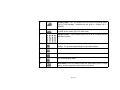
Symbol
Meaning
LIVE
Live state
REC
Record(Manual or continuous)
R A
Alarm record
R M
Motion record
HDD
The use ratio of HDD
V-LOSS
Video loss
USB
USB equipment connected
Press the number key to enter the single-screen mode. If you want to view the image from channel 1 to
channel 16, please press the corresponding number key. For example: To see the picture in channel 3, press
the number key 3; to see the picture in channel 13, press the number key 10+ first and press the key 3
second.
Page 31
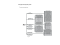
3.2 Login and setup the system
The menu structure chart:
AD MIN PA SS W O R D
USER PA S S WO R D
SY STEM
PA SS W O R D CH E C K
TI M E S ETU P
SEQU EN C E DWELL[FU LL]
SE Q U EN C E DWEL L[ QUAD]
CAM ER A NAM E
CAM ER A STAT US
LI V E
CAM ER A COLO R
PT ZF PR OTOC O L
P TZF ID
TI M E FOR M AT
TI ME OSD FO R M AT
TI M E STA M P FO R M AT
CURREN T STATU S VIEW
VGA PR E Q CHA N GE
SOFTWA R E UPD ATE
DEFA ULT S ETU P
SPO T DWELL
SP O T QUAD D W E LL
VIDEO STANDA R D
MEN U
REC O RD
EV EN T REC
TY P E
NET PA SS W O R D
DELETE REC
NET CLI EN T PO RT
LO CK/UNLOCK REC
NET CLI EN T ID
DELETE ALL REC
NET DVR ID
SEN SO R TY P E
NET CLI EN T ADD R
ALAR M MOTI O N M ANA G ER
NETWOR K TH R O UGHPU T
S ENS O R / A LA RM
REC OPTI ON
SCH EDU LE REC
STORA G E
NETWOR K
REC PR O PERTY
ALAR M SEN S OR M ANA G ER
ALAR M BU ZZER
ALAR M OUTPU T
AUDIO
ALAR M OU T PER I OD
Page 32
There are two users in the origin DVR system. One is Admin which has highest priority to set system’s
configuration and whose password is “0000”, the other is common user which is just allowed to see the live
play and the playback picture and does not have the right to change the user password, which is done by
Admin users.
Operation:
Press the Menu key and enter the ADMIN password, and then you will see the setup menu (Fig 3.2.1
Setup menu). Use the “Up” “Down” “Right” and “Left” buttons to shift cursor, the item selected will be
displayed in yellow. Press the “Enter” key to enter the sub-menu and press the “Menu” key to get back to
the main menu.
Page 33
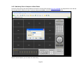
3.2.1 SETUP-SYSTEM
The menu is as above: (Fig 3.2.2 System setup)
ADMIN PASSWORD: Administrator password is “0000” by default, only the administrator has the right
to change it which is comprised of four numbers between 0 and 9 (Fig 3.2.3 Setup admin password).
Page 34
Page 34
Page 34
USER PASSWORD: Common user password is “0000” by default as well. However, only the
administrator is authorized to change it which is comprised of four numbers between 0 and 9.
PASSWORD CHECK: If you choose “ON”, users have to input the password before entering menus.
You can setup the DVR’s configuration if you enter the administrator password. And the common user
password just allows you to the check the live image or saved record; if you choose “OFF”, there is no
limitation on configuration. Anyone can enter the system directly without password. (Fig 3.2.4 Password
check)
TIME SETUP: Use the “Up” “Down” or Left” and “Right” buttons to move the cursor and use the number key
on panel or remote control to modify the value. If the DVR is recording or playing back you can not access this
menu until the recording or playing back is stopped. (Fig 3.2.5 Time setup)
TIME FORMAT: YY/MM/DD: Asian format, Year/Month/Day; DD/MM/YY: European format,
Day/Month/Year; MM/DD/YY: American format, Month/Day/Year. (Fig 3.2.6 Time format)
TIME OSD FORMAT: Time format of live-image.
TOP-WHITE: Time is displayed on top in white
TOP-BLACK: Time is displayed on top in black
BOTTOM-WHITE: Time is displayed at the bottom in white
BOTTOM-BLACK: Time is displayed at the bottom in black
OFF: There is no time displayed in the live-image.
TIME STAMP FORMAT: Time format of plays back mode.
TOP-WHITE: Time is displayed on top in white
TOP-BLACK: Time is displayed on top in black
BOTTOM-WHITE: Time is displayed at the bottom in white
Page 35
BOTTOM-BLACK: Time is displayed at the bottom in black
OFF: There is no time displayed in the play back mode.
CURRENT STATUS VIEW:
Choose “ON”, there will be some information appearing on the screen. For example, HDD quantity, used
ratio of HDD, record mode including manual/alarm/motion etc…
Choose “OFF”, there is no information on the screen.
VGA FREQ CHANGE: (Fig 3.2.7 VGA frequency change)
There are two options to choose: 50Hz and 60Hz. Please choose the suitable one for your VGA monitor.
Page 36
Page 36
SOFTWARE UPDATE: (Fig 3.2.8 Software update)
USB UPDATE: Update firmware from USB flash memory
Press USB UPDATE and below screen will pop up
P
Page 37
Update firmware:
Make sure the updating firmware is on the USB disk
Do not power off the DVR during updating;
Press “ENTER” button to start updating.
Then the system will check the updating firmware
When the updating firmware is found O.K., the system starts to update.
Update process:
Erase the former file;
Check the space for update;
When the space is ready, the software update starts, the percent of update is on the right. It takes
Page 38
about two minutes to update.
When the erase, blank check and update are done, system will check the new program which has
been written.
After the program check is done, the system will restart.
NETWORK UPDATE: The update information is also available on the network, to choose this option
Server IP: The IP address of the network where the firmware is.
File name: The file name of the firmware.
After filling in the two options above, move cursor to “UPDATE”, press “ENTER” button to begin update
from network. The DVR will restart when the software update completed the same as USB update that.
Attention: Please make sure the IP address and the file name are correct.
DEFAULT SETUP: recover the origin configuration setup.
3.2.2 SETUP-LIVE (Fig 3.2.9 Setup live)
SEQUENCE DWELL FULL: Setup the time period between single channel switching, there are 9 options
for users, from 0 second to 9 seconds.
SEQUENCE DWELL QUAD: Setup the time period of four-channel switching, there are 9 options for
users, from 0 second to 9 seconds.
Page 39
CAMERA NAME: Name of the channel. It is comprised of the English letters from “a” to “z” or the numbers
from “0” to “9”.
CAMERA STATUS: If you choose “SHOW”, this image will be displayed on the screen. If you choose
“HIDE”, the image will not be displayed on the screen in live status or in playback status. When the user plays
back this record, change this option as “SHOW”, the image hidden in live status will then be displayed.
CAMERA COLOR: Modify channel color, contrast and brightness. (Fig 3.2.10 Camera color adjust)
PTZF PROTOCOL: Choose the PTZF control protocol for each channel (Fig 3.2.11 PTZF protocol). There
Page 40
are eighteen options for users: PELCO_D-2400, PELCO_D-9600, PELCO_P-4800, PELCO_P-9600,
SCC641-9600, SCC641-19200, SK2161-9600, CNB_102-9600, ADTECH-4800, 15-CD51M-2400, Chubb
iSD-9600, COP1-2400, COP1-4800, COP1-9600, COP1-19200, COP2-9600, 15-CD51M-2400,
DSC230-9600
PTZF ID: Setup the PTZF address, you can choose from “000” to “255”.
SPOT DWELL: 16 channel pictures circulate from 1 to 16. Press “Enter” button to get access to the
configuration setup menu to modify the interval time between two channels switch. The user can use the
number buttons to choose the options—from“0” to “9” seconds. (Fig 3.2.12 Spot dwell)
Page 41
SPOT QUAD DWELL: Channel-switching circulates from quad 1 to quad 4 (The order is: channel
1,2,3,4→channel 5,6,7,8 →channel 9,10,11,12→channel 13,14,15,16→channel 1,2,3,4→…), press “Enter”
button to get access to the configuration setup menu to modify the interval time between two sets of picture
switching. The user can use the number buttons to choose the options—from“0” to “9” seconds.
VIDEO STANDARD: Setup the video style.
There are four options to choose from: AUTO-DETECT, SWITCH, NTSC, and PAL. The DVR can detect
the video automatically if you set this option as AUTO-DETECT, you can also set the video standard manually.
3.2.3 SETUP-REC: Setup the parameter of recording (Fig 3.2.13 Setup record)
REC-PROPERTY: contains REC RESOLUTION, QUALITY and RATE (Fig 3.2.14 Setup record
property).
REC RESOLUTION: The higher the resolution, clearer the picture. The resolution from low to high is:
PAL: 360x288 CIF, 720x288, HalfD1, 720x576, D1; NTSC: 360x240 CIF, 720x240 HalfD1, 720x480 D1.
QUALITY: There are four options to choose from: low, normal, high and best. Higher the quality value,
better the picture.
RATE: The frame rate. If you choose 8, the picture recording rate is 8 frames per second.
The maximum of RATE is different when the REC RESOLUTION is different. For example:
If the record resolution is 720x576(PAL)/720x480(NTSC), there are three frame rates to choose from: 0, 1,
2, the maximum is 2.
If the record resolution is 720x288(PAL)/720x240(NTSC), there are four frame rates to choose: 0, 1, 2, 4,
the
Page 42
maximum is 4.
If the record resolution is 360x288(PAL)/360x240(NTSC), there are five frame rates to choose: 0, 1, 2, 4,
8, the maximum is 8.
Attention: These three factors above decide the quality of picture and the use ratio of HDD.
SETUP- REC OPTIONS: Setup of record option (Fig 3.2.15 Setup record option)
RECORD CONTINUOUS: If you choose “ON”, DVR records continuously in HDD recycle mode. If you
choose “OFF” this function is disabled.
Attention: In Continuous mode, Manual and Alarm record are activated at the same time, the DVR
Page 43
records continuously. If an alarm record occurred, the DVR records continuously and you can find
the alarm event through “event search” or “file search”.
PLAY DEINTERLACE: Interlace scan and play. If you choose “ON”, the DVR will play back after an
internal of line. If you choose the “OFF”, this function is disabled.
Attention: This function is more useful in VGA output mode.
WATER MARK: If you choose “ON”, this function is active. Water mark can protect recording files from being modified, as the modification
can be technically traced by checking watermark. The system will add the invisible code to the record when the “WATER MARK” is on;
this is covered in Chapter 3.3.3 Backup.
Page 44
If you choose “OFF”, this function is disabled.
SETUP-REC-EVENT: Setup of the event record (Fig 3.2.16 Setup event record)
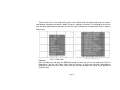
MOTION DETECTION (Fig 3.2.17 Setup motion detection):
AREA: This is the detection area setup
There are three options to choose: ALL, PART, OFF
ALL: All areas of the camera will be detected.
PART: The part of the area selected will be detected. Use the “Up” “Down” “Left” and “Right”
buttons to choose the part needed to be detected and use enter key to select/cancel the part. The part
selected will be in blue and the gray part will not be detected.
OFF: This function will be disabled.
SEN: This is the sensitivity of the motion detection. You can use the remote control or the number
buttons on front panel to set any value of sensitivity from 0 to 9. The higher the value, the more sensitive.
Page 45
[SETUP -RE C-E VENT(S/D)]
Fig3.2.18 Setup sensor detection
SENSOR DETECTION: Each channel matches a relevant Sensor, for example, Channel 2 is linked to
Sensor 4, if the Sensor 4 gives an alarm, the alarm information will be given on the picture by channel 2
(Fig 3.2.18 Setup sensor detection), the “□” means that the channel can not be detected, “V” means that the
channel can be detected.
OPTIONS: (Fig 3.2.19 Setup record time)
POST-RECORD TIME: The length of the recording time after alarm is triggered. You have five
options to choose: 10 seconds, 30 seconds, 1 minute, 5 minutes and 10 minutes.
PRE-RECORD TIME: The length of the recording time before alarm triggered. You have five options
Page 46
To Choose from: 2 seconds, 4 seconds, 6 seconds, 8 seconds and10 seconds.
POP-UP SCREEN: If you choose “ON”, the image will be in full screen when the DVR gives alarm. If
you choose “OFF”, this function is disabled.
SETUP-SCHEDULE-REC: Setup of schedule record (Fig 3.2.20 Setup schedule record)
Press enter key to visit the menu (Fig 3.2.21 Setup schedule record time). “O” means unselected “V”
means selected. Use enter key to switch the status and use menu key to get back to upper level menu.
SU: Sunday
MO: Monday
TU: Tuesday
WE: Wednesday
TH: Thursday
FR: Friday
SA: Saturday
Page 47
[SCHEDULE REC-CH 4]
SU
MO
TU
WE
TH
FR
SA
ALL DAY
AL
Fig3.2.21 setup schedule record time
1
2
“0 1 2 3 4 5 6 7 8 9 0 1 2 3 4 5 6 7 8 9 0 1 2 3” means: “0 1 2 3 4 5 6 7 8 9 10 11 12 13 14 15 16 17 18 19
20 21 22 23”— the 24 hours in a day.
The shortest schedule record interval is one hour. For example, if the first “2” is chosen on the top line,
“MO” is chosen for the day, this means the DVR starts to record at 2:00 AM on Monday and till 3:00
AM; the recording will be one hour. The record file in HDD is divided into many segments, whose length is ten
minutes. There are six record segments in one hour.
DELETE REC: Delete the selected recording list (Fig 3.2.22 Delete file)
Page 48
Press ENTER key to visit the menu, information is given below (Fig 3.2.23 Information of deletion)
“DELETE FILE 0171 200 60407_170000 15AS D U
ARE YOU SURE?
[ENTER]→ YES [MENU]→ NO”
Press ENTER key to delete this record or press MENU key to quit deleting
“0171 200 60407_170000” is a record name.
“U” means unlock, if “U” is displaced by “L”, this record is locked and can not be removed. Please refer to
Appendix C abbreviations explained.
Page 49
LOCK/UNLOCK: Lock/unlock the record. Use enter key to change the status (Fig 3.2.24 Lock/Unlock file).
If the file is locked, then the record can not be deleted or overwritten even though the HDD is full.
DELETE ALL:
If the DVR is recording, the system will Post:
“DELETE ALL
STOP RECORDING AND TRY”
Once the recording is stopped, the system will send reminder that: (Fig 3.2.25 Delete all the file)
“ALL RECORDED FILES WILL BE DELETED
ARE YOU SURE?
[ENTER]→ YES [MENU]→ NO”
Press ENTER key to delete all the records or press MENU key to cancel this operation.
3.2.4 SETUP-STORAGE (Fig 3.2.26 Setup storage)
OVER WRITE: If you choose YES, the DVR will have continuous recording and over write from the
oldest file when HDD is full. The DVR overwrites file from the oldest file. If you choose NO, the DVR
will stop recording when the HDD is full.
FORMAT: Use the “Up” and “Down” keys to choose HDD that you want to format. A warning pops up
after pressing “ENTER”.
“DISK HDD-*
MOUNTED
ARE YOU SURE?
Page 50
[ENTER]→ YES [MENU]→ NO”
(* represents A B C D)
Press enter key to format the HDD, Press menu key to cancel this operation.
Attention: The format time depends on the HDD capacity, the larger the HDD the longer the time. Normally, a 40G HDD takes
about eighty seconds. If a CD/DVD drive is connected to an ATA interface, there will be three HDDs and one CD-ROM displayed.
Page 51
3.2.5 SETUP-NETWORK (Fig 3.2.27 Setup network)
TYPE:
STATIC: Static IP address. Push “Up” “Down” “left” “Right” buttons to move the cursor among the
digits and push ADD or DEC key to modify the IP address. (Fig 3.2.28 Setup static IP).
DYNAMIC: Dynamic IP address. Press ENTER key to display the menu, the system will display
“Please wait” for a while. Then, the IP address which is assigned by network will be displayed on the
screen. If the DVR failed to connect to the network, it will display the information below
DHCP SETTING FAIL
CHECK YOUR NETWORK
Page 52
3.2.5.1 Monitoring From a Computer on Same Router
On the PC Client, open up the Internet Explorer and enter the IP of the DVR (example http://192.168.0.200), you will get below screen with the
login already filled in, default user name is (netuser) and password (0000). just hit OK and you will be connected.
With this Internet Explorer, you can watch live camera only.
Page 53
3.2.5.2 Monitoring From a Remote Computer
Plug the RJ45 cable from the back of DVR to the Switch / Hub or Router.
By Default the network setting on this DVR are as follow:
IP ADDRESS: 192.168.1.200
Subnet: 255.255.255.0
Gateway: 192.168.1.1
From a PC connected to the same Router, find the IP address by typing IPCONFIG at command prompt. (START-RUN- type in CMD) then type
in IPCONFIG. Find the IP, Gateway and Subnet.
If the IP is 192.168.1.xxx, then you don’t need to do anything else.
But if the IP is something like this: 192.168.0.xxx. Gateway: 192.168.0.1. Then you need to change the IP of DVR by going to the MENU
of DVR and go to NETWORK and push ENTER on STATIC IP and change the IP to: 192.168.000.200 and the Gateway to
192.168.000.001.
Then refer to the manual of your Router, go to the Router Setup and you need to use PORT FORWARDING to forward port 80 and a
range of 7620 – 7624 to the IP: 192.168.0.200. (in the case of our example).
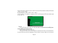
EXAMPLE OF PORT FORWARDING IN THE LINKSYS ROUTER
If you do not have your manual, here is the link where you can find out how to do port forwarding from different brands of Routers:
http://www.portforward.com/english/routers/port_forwarding/routerindex.htm
Monitoring the camera on a Remote Computer on Internet
You need to find out the WAN IP of the Router where the DVR connected to by going to www.myipaddress.com. From the PC connected
to the same Router the DVR connected to. Then from the remote location, enter this IP into Internet explorer, or you can use the
Netclient Software.
Page 54
Port 1 is used for logon;
Port 2 is used for controlling the DVR;
Port 3 is used for live surveillance;
Port 4 is used for backup;
Port 5 is used for playing back.
NET CLIENT ID: The default ID is “NetUser”, the user can set other four IDs and passwords for
viewing through the network. (Fig 3.2.31 Net client ID).The login-ID and the password are composed of t
letters or numbers at random. Only the ID set here or the default ID can be used in the remote viewer. The
administrator can restrict the other users to remote viewing through the internet with this configuration
setup.
NET DVR ID: The identification of the DVR. You can edit it at will, it can be composed of numbers,
letters, and symbols.
NET CLIENT ADDR (address) (Fig 3.2.32 Net client address): Fill in these options with the
network information needed. Use the “Up” “Down” “Left” “Right” buttons and ENTER key to fill the blank.
“<000.000.000.000>” means that any IP address can access the DVR through network. The user can set up
ten IP addresses as restricted IPs to access the DVR.
Page 55
3.2.5.3 Play Back Recorded File
To play back the recorded file, you need to use the CLIENT Software.
Install the NETCLIENT Software and run netclient.exe, you will get the below screen and click on CONNECT and enter the IP, login name is
“netuser” and password “0000”.
From this program you can do REMOTE PLAYBACK (R-PB) or BACK UP and LOCAL PLAY BACK (L-PB)
Page 55
Page 56
NETWORK THROUGHPUT: To setup the transfer speed of the DVR in the network. There are nine
options to choose from: unlimited, 64KBPS, 128KBPS, 256KBPS, 512KBPS, 1MBPS, 2MBPS, 4MBPS,
10MBPS. Users can choose the option according to the demand (Fig 3.2.33 Setup net work throughput).
3.2.6 SETUP-SENSOR/ALARM (Fig 3.2.34 Setup sensor/alarm)
SENSOR TYPE
Press ENTER to visit the next level menu where there are two options to choose from: NO and NC.
“NO” means normal open. If “NO” is chosen, the DVR will set off alarm if the alarm is at low level.
Page 57
“NC” means normal close. If “NC” is chosen, the DVR will set off the alarm if the alarm is at high level.
ALARM MOTION MANAGER (Fig 3.2.35 Alarm motion manager)
“□” means unselected “V” means selected, “Abscissa” means the channel number, “Ordinate” means
annunciator number.
Every channel is able to trigger multiple alarms. For example, if user selects alarm 1, alarm 2 and alarm 3
for channel 1, then if there is motion detected in channel 1, alarm 1, alarm 2, and alarm 3 send alarm
signals at the same time.
Every alarm can work for multiple channels. For example, if user selects channel 1, channel 2 and
Page 58
channel 3 for alarm 1, then if any of the 3 channels detect a motion event, alarm 1 will send signal.
ALARM SENSOR MANAGER (Fig 3.2.36 Alarm sensor manager)
“□” means unselected “V” means selected, “Abscissa” means the sensor number and “Ordinate” means
annunciator number.
Every sensor is able to trigger multiple alarms. For example, if user selects alarm 1, alarm2 and alarm 3
for sensor 1, then once sensor 1 is activated, alarm 1, alarm 2 and alarm 3 will send alarm signals at the
same time.
Every alarm can work for multiple sensors. For example, if user selects sensor 1, sensor 2 and sensor 3
Page 59
for alarm 1, if any of the 3 sensors are activated, then alarm 1 will send an alarm signal.
ALARM BUZZER (Fig 3.2.37 Alarm buzzer)
ON: Start the buzzer when DVR gives alarm
OFF: The buzzer will not be triggered when DVR detects alarm
ALARM OUTPUT (Fig 3.2.38 Alarm output)
ON: Alarm on. When the alarm output is on, the DVR will send alarm when the sensor is triggered or a
motion event occurs.
OFF: Alarm off. The DVR will not send alarm when output is off.
Page 60
ALARM OUT PERIOD (Fig 3.2.39 Alarm output period)
Alarm continuing time. There are five options to choose: 30 seconds, 1 minute, 3 minutes, 10 minutes and
Continuous.
3.2.7 SETUP-AUDIO
“■” means unselected “V” means selected, “Abscissa” indicates the channel number and “Ordinate”
indicates audio output number. (Fig 3.2.40 Audio output)
Page 61
There are four audio input ports and one audio output port in all. One audio input matches one channel.
For example, if user selects audio A for channel 1, channel 1 will record on audio A.
3.3 Function
Press the Function button to enter the basic function menu (Fig 3.3.1 Function menu), which contains the
following items:
STATUS
AUDIO
BACKUP
PAN/TILT
ZOOM/FOCUS
LOG LIST
3.3.1 STATUS
Press the Info button on the remote control, the screen will display the firmware version number, HDD
status, Network status and recording information. (Fig 3.3.2 Status view) If a CD/DVD drive i s connected
to a n ATA interface, there will be three HDDs and one CD-ROM displayed.
Page 62
[STAT US]
S/W VER: V1.0. 10-tv_16
(06/05/08 10:07)
[HDD] A: 150G(63%) B: NONE
D: NO NE
C: NO NE
NETWO RK:
MAC: 00.0E.B5.00.06.32
DDNS: SERVER (null) FAIL
[REC]
SIZE
720*576
CH RA QUAL CH RA QUAL CH RA QUAL CH RA QUAL
1 2 BEST 5 2 BEST 9 2 BEST 13 2 BEST
2 2 BEST 6 2 BEST 10 2 BEST 14 2 BEST
3 2 BEST 7 2 BEST 11 2 BEST 15 2 BEST
4 2 BEST 8 2 BEST 12 2 BEST 16 2 BEST
Fig3.3.2 Status view
3.3.2 AUDIO
AUDIO ON: Activate the audio output; MUTE: Disable the audio output
Page 63
3.3.3 BACKUP & VIEW BACKUP
Backup
Press the Backup button (Fig 3.3.3 Setup backup). This DVR supports five media types: CD-R, CDRW, DVD-R, DVD-RW, USB-MEMORY (Including USB flash drive and mobile hard disk), and
supports backup to DVD-RW, CD-RW, internally and as well as USB externally. Please refer to list of
compatible DVD-RW & CD-RW drives, which may be updated from time to time.
MEDIA TYPE: Press ENTER button to access the next menu (Fig3.3.4 Setup media type), if you plan to
Page 64
backup to CD-R, choose CD-R; if you plan to backup in CD-RW, choose CD-RW, etc…
BACKUP BASE: If you want to search the file needed to backup by file name, choose FILE; if you
want to search the file needed to backup by time, choose TIME. Each method is in the Chapter—START.
CHANNEL: If you want to backup the four channels, please choose ALL, if you want to backup several
of the four channels, choose PART. Then move the cursor to the blank of the channel needed to backup.
There will be a white dot in the blank before the selected channel.
START: The backup’s beginning; you can choose the file from the file table.
Page 65
If the backup base is “FILE”, the “START” choose menu is as shown in Fig 3.3.5 Backup start (file)
If the backup base is “TIME”, the “START” choose menu is as shown in Fig 3.3.6 Backup start
(calendar) and Fig 3.3.7 Backup start (time). First, choose the date, then, choose the time.
[BACKUP-TIME]
USB BACKUP
USB BA CKUP
HOUR:
MIN:
TIME
50%
000000
Fig3.3.8 USB Backup process
END: The backup’s end, setup method is the same as the START.
After setting up MEDIA TYPE, FILE FORMAT, BACKUP BASE, CHANNEL, START, and END, the
DVR is ready to backup.
BACKUP
Press the BACKUP button, the DVR begins to backup; there is a progress b a r on the
Page 66
screen at the same time as the backup. The USB backup process is s h o w n in Fig 3.3.8- USB backup
process
showing, that is the same as backup with the CD/DVD driver.
When the backup is over, a dialogue box will pop up. If the user backup in the USB memory, the sentence
in the dialogue box is:
“FLASH
BACKUP OK”
When you receive this message the backup is completed.
Cancel:
If the user wants to change the backup file or cancel the backup, move cursor to “CANCEL” and press
“ENTER” button.
Attention:
Only CD-R or CD-RW media can be used when the user backup file with CD drive;
CD-R, CD-RW, DVD-R or DVD-RW media can be used to backup file to DVD drive.
View backup:
The software to view the backup recording is packed automatically in the file.
Here is the Icon of the backup viewer:
P
— “Backup_viewer”
Page 67
Brief introduction of buttons:
: Play
: Pause
: Stop
: Fast backward
: Step forward
: Step backward
: Fast forward
: Verify if the record has been changed or not
: Snap shot
: Volume control
: Number button
/
/
1-channel/4-channel/9-channel/16-channel mode
/
You can use number button to choose the channel which you want to see.
Page 68
The main menu of the Backup viewer:
Introduction to W.M Check, SnapShot.
W.M Check (Water Mark Check):
While the backup file is paused, click this button to check water mark:
Page 69
After a few minutes, the result will pop up. If the backup file has been changed or moved, the system will
display “Watermark Check Fail”, if the backup file has not been changed or moved, the system will
prompt “Watermark Check Ok”.
SnapShot: Click SnapShot button, a picture pops up for saving or printing. The user can select
directory to save, and can print it directly.
Snap Again:
If you want to snap the next picture, Please press the “Snap Again” button.
Save:
When you click the “OK” button, a dialog box pops up for save location. Fill in file name and choose the
file type, then click
Print:
If you want to print this picture, press PRINT, the dialog box of printer setup will be displayed. If you do
not want to print it, press CANCEL.
Page 70
3.3.4 PAN/TILT
Move cursor to PAN/TILT in the function menu, press ENTER button to access this menu (Fig 3.3.9
PAN/TILT) to control the Fast Speed Dome. This particular operation is as follows:
Switch to the channel which connects to the Fast Speed Dome video output. The “Up” “Down”
“Left” “Right” buttons control the Fast Speed Dome to swing up, down, left or right, press “ENTER” button to
stop swinging.
The user can also enter this menu directly by pressing the P/T button on the front panel or the remote
control.
3.3.5 ZOOM/FOCUS
Move cursor to ZOOM/FOCUS in the function menu, press ENTER button to access this menu
(Fig 3.3.10 ZOOM/FOCUS) to control this function of the Fast Speed Dome. This particular operation is as
follows:
Switch to the channel which connects to the Fast Speed Dome video output. Through the “Up” “Down”
buttons to control the Fast Speed Dome to zoom-in and zoom out. Use “Left” “Right” buttons
to control Fast Speed Dome’s short and long focus.
The user can also enter this menu directly by pressing the Z/F button on the front panel or the remote
control.
Page 71
PAN/ TILT
ZOOM/FOCUS
Z+
F+
F-
AUTOPAN
ENTER
Z<<Ch1>>
<<Ch1>>
Fig3.3.9 PAN/TILT
Fig3.3.10 ZOOM/F OCUS
3.3.6 SEQUENCE
Press “SEQ” button to enter the sequence play status.
If the current screen shows a single channel, press “SEQ” button to play the sixteen channels one by
one in order.
If the current screen shows the image of sixteen channels, press “SEQ” button to play the sixteen
channels four channels at a time in order.
Page 72
3.3.7 LOG LIST
Press the Log button on the remote control, the system will enter the setup menu of log file (Fig 3.3.11
Setup log file).
LOG FILE: If you choose ALL, the following options will be displayed: MOTION, SENSOR, ALARM, VLOSS, SYSTEM, HDD, FLIE, DB, POWER, NET.
If you choose PART, you should choose the option needed manually. There is a white dot in the blank after
the options selected.
Page 73
FROM: The beginning time of the log file, you can use the number key to change the time.
TO: The end time of the log file, you can use the number key to change the time.
Press the OK option, the system will enter the event log view (Fig 3.3.12 Event log view): Use “Up” “Down”
buttons to move the cursor to the log file needed. If there is a long log list, user can use “<”
button to page up, use “>” button to page down, use “RW” button to jump to the last list, and press “FF” button
to jump to the first list. Press “ENTER” button to see the explanation. (Fig 3.3.13 Explanation) Press “ENTER”
button again to return to the event log list menu.
EVENT EXPLAIN
1818 060704: 151610 FL DEL: / hdd b/ 20060629_081000_nCm.ps
The particular meaning of each section above:
1818: The number of the deleted file.
060704: The date the file was deleted.
151610: The time the file was delected.
FL: It means that file loss event occurred.
DEL: It means that the file was deleted.
Hdd: It means the file was deleted from the hard disk.
20060629_081000_nCm.ps: The file name.
Page 74
3.4 Search record
Press the “Search” button on the remote control, there are three search modes which will be displayed
on the screen (Fig 3.4.1 Search)
TIME SEARCH
EVENT SEARCH
FILE SEARCH
Attention: Search recordings by time search or file search, search all event recordings by event
search.
Page 75
TIME SEARCH:
Attention: All the records can be searched in this menu.
Operation:
Date choose:
Press ENTER to access the CALENDAR TIME menu, Use “Up” “Down” “Left” “Right” buttons to move
cursor to the date needed to search.(Fig 3.4.1 Date choose). A time which had an event record is shown in
yellow font.
<<2006-05>>: Year-Month
<<: Backward, when the cursor moves to this sign, it will be in yellow, then press ENTER to take the month
backward. For example: the current month is 2006-05, press ENTER once, the month will be changed
to
2006-04.Press ENTER again, the month will be changed to 2006-03.
>>: Forward, when the cursor moves to this sign, it will be in yellow, then press ENTER to take the
month forward. For example: if the current month is 2006-05, press ENTER once, the month will be
changed to 2006-06. Press ENTER again, the month will be changed to 2006-07.
Page 76
Time choose:
Below the Year-Month setup, there is the calendar of one month. The selected date is
in green, press ENTER to select the time choose menu. (Fig 3.4.2 Time choose-Page 79).
The time displayed in green has a record file. Use “Up” “Down” “Left” “Right” buttons to move to the
selected time—hour and minute.
Press ENTER button to view the record chosen, the “Forward” “Backward” “Play/pause” buttons can be
used to control the record playing. Press “STOP” button to get back to live picture.
Page 77
EVENT SEARCH
Attention: Only alarm events and motion events record can be searched in this menu.
Operation:
Select the date, whose method is the same as TIME SEARCH. A time which has event record is
shown in yellow font.
Press “ENTER” to access the event menu after selecting time. (Fig 3.4.3 Event choose).
Analyze the record information. Take one of the event records information as example.
The meaning of the sections:
“0691 060517:113145 FL MD 06”
“0691”: Serial number
“060517”: Date, the first and the second stand for year, the third and the fourth stand for month, the fifth
and the sixth stand for day. “060517” means May 17th, 2006.
“113145”: Time, the first and the second stand for hour, the third and the fourth stand for minute, the fifth
and the sixth stand for second. “113145” means 11:31:45.
“MD”: Motion detection.
“06”: The length of record time.
Select the record and press the “ENTER” button to view.
Use “Up” “Down” buttons to choose the event record, press ENTER button to view the record chosen,
The “Forward” “Backward” “Play/pause” buttons can be used to control the record playing. Press “STOP” button
to get back to live picture.
If the event list is long, user can move to the page needed though “PGUP” “PGDN” “LAST”
“FIRST”, the meaning of these signs and shortcut keys are in the following table.
Page 78
[SEARCH TIME]
HOUR:
MIN:
TIME
00
00 00
Fig3.4.2 Time choose
Sign
Meaning
Shortcut key
PGUP
Page up, to the previous
PGDN
Page down, to the next
Left button
LAST
To the last page
Backward button
To the first page
Forward button
FIRST
Page 79
Right button
FILE SEARCH
Attention: All the records can be searched in this menu.
Operation:
Select the date, by the same method as TIME SEARCH. A time which has an event record is shown
in yellow font.
Press “ENTER” to access the play file list. (Fig 3.4.4 File search)
Analyze the record information. Taking one of the file records as an example. The
meaning of the sections:
“194 20060517_113206 46S D L W”
“194”: Serial number
“20060517”: Date, the ex-four digitals stand for year, the fifth and the sixth stand for month, the seventh
and the eighth stand for day. “2006060517” means may 17th, 2006.
“46S”: The length of record time.
“D”: Resolution, D means the 720*576 in PAL or 720*480 in NTSC.
“L”: Lock. Please refer to Appendix C for an explaination of abbreviations.
“W”: Water mark. If the option for “water mark” is set to “ON’, the letter “w” would be displayed in the file
search menu.
Page 80
Use “Up” “Down” buttons to choose the file record, Press the “ENTER” button to view the record chosen,
the “Forward” “Backward” “Play/pause” buttons can be used to control the recording. Press “STOP” button
to go back to live picture
If the event list is too long for one page, user can move to the page needed though “PGUP” “PGDN”
“LAST” buttons.
“FIRST”, the meaning of these signs and shortcut keys are in the table above.
The record was divided into many sections automatically. The default length of one section is ten minutes
(600 Seconds). Length may be shorter than 1 hour, depending on actual motion recording, alarm recording
and schedule setup.
3.5 SPOT
Connect the DVR to a SPOT monitor by the SPOT port, and then press the “SPOT” button on the
remote control to setup. (Fig 3.5.1 SPOT setup)
There are four options to choose from: CHANNEL, SEQ SINGLE, SEQ QUAD and SEQ STOP.
If you choose “CHANNEL”, then you should choose the channel number in the blank below. The spot
monitor will display the image of just the channel selected.
If you choose “SEQ SINGLE”, the spot monitor will display images of all the channels in order.
If you choose “SEQ QUAD”, the spot monitor will display images of all the channels in order by quad
(groups of four).
If you choose “SEQ STOP”, the spot monitor stops sequence playing.
Attention: There is no setup menu in the screen of the spot monitor.
Page 81
Page 82
Appendix
Appendix A: Main Standard & Parameter chart
Model
16Channel
VIDEO
Input Channel
16CH
Input Level
1.0Vp-p±10% Composite, 75Ohm Balanced
Video Standard
Auto / NTSC / PAL
Main TV Out
1.0Vp-p Composite, 75Ohm Balanced
Screen Split Control
1, 16Screen
Screen Rotation Control
1~9Seconds
Display
Resolution
NTSC
720(H)x480(V)
PAL
720(H)x576(V)
NTSC
Speed
PAL
Live
480FPS
Playback 120FPS
Live
400FPS
Playback 100FPS
Page 83
Function
Auto Sequence Screen Split, PIP
AUDIO
Compression
ADPCM
Audio In / Out
4CH /1CH
Input Level
TBD(0.5~1.4Vp-p@20Kohm)
RECORDING
Compression
Resolution
Speed
MPEG4
NTSC
720(H)x480(V), 720(H)x240(V), 360(H)x240(V)
PAL
720(H)x576(V), 720(H)x288(V), 360(H)x288(V)
NTSC
PAL
360 x240
Max 120FPS
720 x240
Max 60FPS
720 x480
Max 30FPS
360 x288
Max 100FPS
720 x288
Max 50FPS
720 x576
Max 25FPS
Data Size
2~5KB(CIF)
Mode
Continuous, Schedule, Motion detection, Sensor
Schedule
24Groups per day by an hour
Pre-Alarm
5~10Seconds
HDD
Internal Storage
Max. 4HDD
Page 84
Speed
5400RPM, 7200RPM
Type
EIDE compatible
SEARCHING & PLAYBACK
Searching Method
Time, Event, File
REMOTE SURVEILLANCE
Monitoring Environment
Client Software, Web Browser
ALARM
Sensor Input
16Ports
Alarm Output
4 TTL-Out(Programmable), Terminal
Motion Detection
Available For Each Camera Multi Detection Level
CONNECTOR
Video Input
BNC 16Ports
Main Monitor Output
BNC 1Port
Spot Monitor Output
BNC 1Port
S-Video (Main TV)
BNC 1Port (4Pins mini DIN)
VGA Output
BNC 1 Port (15Pins female DSUB)
Audio Input (Mono)
RCA 4 Audio Jack (Live Only)
Audio Output (Mono)
RCA 1Port
External Control (RS-232C)
OK
Firmware Upgrade
USB 2.0
Page 85
External Control (RS-422/485)
Terminal Block
Sensor Input
Terminal Block
Alarm Output
Terminal Block
PTZ (RS-485)
2Pins Terminal Block
Ethernet
RJ-45, 10/100Mbps
USB 2.0
2Ports
ELECTRICAL
Power Source
115~230VAC (50~60Hz)
Power Consumption
TBD(App. 50 ~ 60Watt)
BACKUP
Digital Backup
Network, External CD/DVD RAM, USB Storage
External CD/DVD RW
USB 2.0
OTHERS
OS
Embedded Linux
Duplexer or Triplex
Triplex
Control Device
Front key, Remote controller
PTZF
By menu
OSD Language
Multiple
Dimension
432mm(W)x98mm(H)x463mm(D) {17 x 3 7/8 x 18 1/4in}
Attention: This chart uses 16-channel DVR as an example.
Page 86
Appendix B Record capability
Picture
Quality
Best
High
Normal
Low
Best
High
Normal
Low
Best
High
Normal
Low
Resolution
720*576
720*576
720*576
720*576
720*288
720*288
720*288
720*288
360*288
360*288
360*288
360*288
--how much capability does record engross per hour
PAL
NTSC
Total Frame Rate Capability Resolution Total Frame Rate
25F/S
3.80G
720*480
30F/S
1.91G
720*480
25F/S
30F/S
25F/S
0.96G
720*480
30F/S
0.83G
720*480
25F/S
30F/S
4.10G
720*240
50F/S
60F/S
50F/S
2.60G
720*240
60F/S
1.28G
720*240
50F/S
60F/S
0.98G
720*240
50F/S
60F/S
100F/S
3.42G
360*240
120F/S
100F/S
2.25G
360*240
120F/S
100F/S
120F/S
1.21G
360*240
100F/S
1.05G
360*240
120F/S
Capability
3.75G
2.34G
1.20G
0.80G
3.94G
2.42G
1.40G
0.83G
3.62G
2.27G
1.25G
0.98G
Note: The above figures are from our tests which are just for user’s reference. Different definition and
stabilization (object’s movement) of the images will give different results.
Page 87
Appendix C: The meaning of some abbreviations
Letters
Meaning
Letters
Meaning
D
720*576(PAL)/720*480(NTSC)
H
720*288(PAL)/720*240(NTSC)
C
360*288(PAL)/720*240(NTSC)
NT
A network event
U
Unlock
L
lock
MD
Motion detection
SD
Sensor detection
PW
An event of power on occurred
VL
Video loss
AL
Alarm
DB
The data base recurred or united
HD
An event concerning HDD occurred
TM
Time change
SY
An event of system setup or system
reset
FL
A file was created or deleted
DVR
Digital video recorder
DEL
File was deleted
Page 88


![[Proxyview]User`s Manual (5.1.4.0)](http://vs1.manualzilla.com/store/data/005658349_1-e7f841297d622d23913e7f3fcabf599d-150x150.png)