1
User Guide
3Com Wireless 8760 Dual-radio 11a/b/g
PoE Access Point
3CRWE876075 / WL-546
www.3Com.com
Part Number 10015153 Rev. AA
Published June, 2006
3Com Corporation
350 Campus Drive
Marlborough, MA
01752-3064
Copyright © 2006 3Com Corporation. All rights reserved. No part of this documentation may be reproduced in any form or by any
means or used to make any derivative work (such as translation, transformation, or adaptation) without written permission from
3Com Corporation.
3Com Corporation reserves the right to revise this documentation and to make changes in content from time to time without
obligation on the part of 3Com Corporation to provide notification of such revision or change.
3Com Corporation provides this documentation without warranty, term, or condition of any kind, either implied or expressed,
including, but not limited to, the implied warranties, terms or conditions of merchantability, satisfactory quality, and fitness for a
particular purpose. 3Com may make improvements or changes in the product(s) and/or the program(s) described in this
documentation at any time.
If there is any software on removable media described in this documentation, it is furnished under a license agreement included with
the product as a separate document, in the hard copy documentation, or on the removable media in a directory file named
LICENSE.TXT or !LICENSE.TXT. If you are unable to locate a copy, please contact 3Com and a copy will be provided to you.
UNITED STATES GOVERNMENT LEGEND
If you are a United States government agency, then this documentation and the software described herein are provided to you
subject to the following:
All technical data and computer software are commercial in nature and developed solely at private expense. Software is delivered as
“Commercial Computer Software” as defined in DFARS 252.227-7014 (June 1995) or as a “commercial item” as defined in
FAR 2.101(a) and as such is provided with only such rights as are provided in 3Com’s standard commercial license for the Software.
Technical data is provided with limited rights only as provided in DFAR 252.227-7015 (November 1995) or FAR 52.227-14 (June
1987), whichever is applicable. You agree not to remove or deface any portion of any legend provided on any licensed program or
documentation contained in, or delivered to you in conjunction with, this User Guide.
Unless otherwise indicated, 3Com registered trademarks are registered in the United States and may or may not be registered in
other countries.
3Com, the 3Com logo, and SuperStack are registered trademarks of 3Com Corporation.
Wi-Fi is a trademark of the Wireless Ethernet Compatibility Alliance.
All other company and product names may be trademarks of the respective companies with which they are associated.
EXPORT RESTRICTIONS: This product contains Encryption and may require US and/or Local Government authorization prior to
export or import to another country.
Contents
1
Introduction
Product Features 1-2
Security 1-2
Performance and Reliability 1-3
Virtual Access Point (VAP) Support 1-3
WDS Bridging and Spanning Tree Protocol (STP) Support
Manageability 1-4
Wireless Network Standards 1-4
802.11g 1-4
802.11a 1-5
Approved Channels 1-5
2
Installing the Access Point
Installation Requirements 2-1
Power Requirements 2-2
Safety Information 2-2
Deciding Where to Place Equipment and
Performing A Site Survey 2-3
Before You Begin 2-4
Connecting the Standard Antennas 2-5
Connecting Power 2-6
Using the Power Supply 2-8
Using a Power-Over-Ethernet LAN Port 2-8
Checking the LEDs 2-9
Reset Button 2-9
Wall, Ceiling, or Electrical Box Mounting 2-10
Flat Surface Installation 2-12
Selecting and Connecting a Different Antenna Model
Installing Software Utilities 2-14
3
2-12
1-3
3
Initial Configuration
Networks with a DHCP Server 3-1
Networks without a DHCP Server 3-1
Using the 3Com Installation CD 3-2
Launch the 3COM Wireless Infrastructure Device Manager (Widman)
utility 3-2
Launching the 3com Wireless Interface Device Manager 3-2
First Time Only 3-4
Using the Setup Wizard 3-4
4
System Configuration
Advanced Setup 4-2
System Identification 4-4
TCP / IP Settings 4-5
RADIUS 4-8
Authentication 4-9
Filter Control 4-14
VLAN 4-16
SNMP 4-18
Configuring SNMP and Trap Message Parameters
Configuring SNMPv3 Users 4-21
Administration 4-22
Changing the Password 4-22
Telnet and SSH Settings 4-23
Upgrading Firmware 4-24
WDS and Spanning Tree Settings 4-27
System Log 4-33
Enabling System Logging 4-33
Configuring SNTP 4-34
Radio Interface 4-35
802.11a Interface 4-36
Configuring Radio Settings 4-36
Configuring Common Radio Settings 4-38
802.11b/g Interface 4-42
Configuring Wi-Fi Multimedia 4-44
Security 4-49
Wired Equivalent Privacy (WEP) 4-52
4
4-18
Wi-Fi Protected Access (WPA)
5
4-56
Command Line Interface
Using the Command Line Interface 5-1
Accessing the CLI 5-1
Console Connection 5-1
Telnet Connection 5-2
Entering Commands 5-3
Keywords and Arguments 5-3
Minimum Abbreviation 5-3
Command Completion 5-3
Getting Help on Commands 5-3
Showing Commands 5-4
Partial Keyword Lookup 5-4
Negating the Effect of Commands 5-5
Using Command History 5-5
Understanding Command Modes 5-5
Exec Commands 5-5
Configuration Commands 5-6
Command Line Processing 5-6
Command Groups 5-7
6
Troubleshooting
Index
5
6
TERMINOLOGY
Access Point—An internetworking device that seamlessly connects
wired and wireless networks.
Ad Hoc—An ad hoc wireless LAN is a group of computers, each with
wireless adapters, connected as an independent wireless LAN.
Backbone—The core infrastructure of a network. The portion of the
network that transports information from one central location to another
central location where it is unloaded onto a local system.
Base Station—In mobile telecommunications, a base station is the
central radio transmitter/receiver that maintains communications with the
mobile radiotelephone sets within its range. In cellular and personal
communications applications, each cell or micro-cell has its own base
station; each base station in turn is interconnected with other cells’ bases.
BSS—Basic Service Set. It is an access point and all the LAN PCs that are
associated with it.
CSMA/CA—Carrier Sense Multiple Access with Collision Avoidance.
EAP—Extensible Authentication Protocol, which provides a generalized
framework for several different authentication methods.
ESS—Extended Service Set. More than one BSS is configured to become
an ESS. LAN mobile users can roam between different BSSs in an ESS
(ESS-ID, SSID).
Ethernet—A popular local area data communications network, which
accepts transmission from computers and terminals.
Infrastructure—An integrated wireless and wired LAN is called an
infrastructure configuration.
RADIUS—Remote Access Dial-In User Server is an authentication method
used in conjunction with EAP for 802.1x authentication and session
based keys.
Roaming—A wireless LAN mobile user moves around an ESS and
maintains a continuous connection to the infrastructure network.
RTS Threshold—Transmitters contending for the medium may not be
aware of each other (they are “hidden nodes”). The RTS/CTS mechanism
can solve this problem. If the packet size is smaller than the preset RTS
Threshold size, the RTS/CTS mechanism will not be enabled.
7
VAP—Virtual Access Point. An access point radio capable of operating as
four separate access points.
VLAN—Virtual Local Area Network. A LAN consisting of groups of hosts
that are on physically different segments but that communicate as
though they were on the same segment.
WEP—Wired Equivalent Privacy is based on the use of security keys and
the popular RC4 encryption algorithm. Wireless devices without a valid
WEP key will be excluded from network traffic.
WDS—Wireless Distribution System.
WPA—Wi-Fi Protected Access.
8
1
INTRODUCTION
The 3Com® Wireless 8760 Dual-radio 11a/b/g PoE Access Point offers a
dual-mode architecture that supports 802.11g, 802.11a, and 802.11b wireless
users on a single device. This means you can mix and match radio bands to meet
different coverage and bandwidth needs within the same area.
With their flexibility and unfettered access, wireless LANs are changing the way
people work. Now with 3Com’s enterprise-class wireless access point, you can
build a cost-effective, reliable, secure wireless network that provides users with
seamless connectivity to the Internet, company intranet, and the wired corporate
network from anywhere they happen to be—conference room, cafeteria or
office.
3Com’s dual-mode design supports 802.11g, 802.11a, and 802.11b wireless
standards on a single access point. This capability increases configuration and
coverage flexibility and protects your network investment for both existing and
emerging wireless standards.
Industry-leading security features and comprehensive management and
performance features combine to make these enterprise class wireless access
points an ideal choice for organizations ready to serve their increasingly mobile
workforce.
1-1
CHAPTER 1: INTRODUCTION
PRODUCT FEATURES
Access Point 8760—Creates an enterprise-class wireless LAN supporting up to
256 simultaneous users. The access point supports two radios and external
antennas including WDS bridging ability on both radios.
SECURITY
3Com offers one of the most robust suite of standards-based security on the
market today.
To protect sensitive data broadcast over the wireless LAN, 3Com supports WPA
and WPA2 security standards. 3Com strengthens this basic security mechanism
with additional security features, including:
MAC address access control lists
IEEE 802.1x per-port user authentication with RADIUS server support
IEEE 802.1x supplicant support
SSH v2
HTTP/HTTPS
SNMP v3
Legacy WEP 40/64 bit, 128 bit and 152 bit
Wireless Protected Access (WPA) and WPA2
Extensible Authentication Protocol (EAP) support: EAP-MD5, EAP-TLS,
EAP-TTLS, and PEAP
1-2
Product Features
PERFORMANCE AND RELIABILITY
3Com wireless access point performance features ensure reliable and seamless
connections for users wherever they roam:
Automatic channel selection automatically finds the least loaded channel for
interference-free communication.
Auto network connect and dynamic rate shifting keep users connected
through a wide variety of conditions by changing to the optimum connection
speed as they move through the network.
Virtual Access Point (VAP) support provides flexibility by allowing a single
access point radio to operate as up to four separate access points.
Wireless Distribution System (WDS) Bridging support allows you to create
large wireless networks in areas where pulling wires is restricted or
cost-prohibitive by linking several wireless access points together with WDS
links.
Virtual Access Point (VAP) Support
Virtual Access Point (VAP) support allows an access point radio to operate as four
separate access points, providing multiple wireless services to clients in a network.
Each VAP can be configured to provide access to different network resources and
can support different levels of security.
For example, in a university network, an access point (AP) could be used to offer
two services: The first service provides access to protected data for authenticated
university staff members, while the second service provides open access to the
Internet for unauthenticated users, such as students or visitors.
Up to four VAPs per radio are available, and each VAP can be configured with its
own security settings.
For information on setting up and configuring VAPs, see “Wired Equivalent
Privacy (WEP)” on page 4-52.
WDS Bridging and Spanning Tree Protocol (STP) Support
A Distribution System (DS) is a network (typically a wired network) that
interconnects separate access points into a single LAN. With WDS, the
interconnection no longer needs to be physically wired. WDS uses the wireless
medium to interconnect separate access points, thereby eliminating the cost and
inconvenience that may hinder wire installations.
A WDS link can be used in a simple point-to-point link, a complex
point-to-multipoint link, or a multilayer topology.
1-3
CHAPTER 1: INTRODUCTION
MANAGEABILITY
3Com offers a wide range of standards-based management support, from SNMP
to 3Com Network Supervisor and HP OpenView for seamless integration with
your wired network.
Wireless Infrastructure Device Manager lets you configure parameters, run
diagnostics, backup and restore configurations, and monitor performance from
anywhere on the network using an embedded web server browser.
With Power over Ethernet (PoE) support, the same Category 5 cable that
connects your access point to the data network also provides its power. A single
cable installation dramatically improves your choice of mounting configurations
because you no longer need to consider AC power outlet locations. PoE support
makes it easier than ever to overcome installation problems with difficult-to-wire
or hard-to-reach locations.
WIRELESS NETWORK STANDARDS
Understanding the characteristics of the 802.11g and 802.11a standards can help
you make the best choice for your wireless implementation plans.
802.11G
802.11g operates in the 2.4 GHz band at up to 54Mbps, and supports the widest
coverage—up to 100 meters (328 feet). However, is subject to a greater risk of
radio interference because it operates in the more popular 2.4 GHz band.
For those organizations demanding even higher speeds, a “turbo mode” feature
can boost throughput rates up to 108 Mbps. Consider 802.11g when you need
wider coverage and vendor compatibility and you are:
Maintaining support for existing 802.11b users and the existing wireless
investment while providing for expansion into 802.11g.
Implementing a complete wireless LAN solution, including bridges, gateways,
access points and clients; Wi-Fi certification guarantees compatibility
among vendors
Providing access to hot spots in public spaces such as coffee shops or
university cafeterias
1-4
Wireless Network Standards
802.11A
802.11a operates at the 5 GHz band and supports data rates at up to 54 Mbps.
For those organizations demanding even higher speeds, a “turbo mode” feature
can boost throughput rates up to 108 Mbps. And because there are fewer
devices in the 5 GHz band, there’s less potential for RF interference. However,
because it is at an entirely different radio spectrum, it is not compatible with
802.11g.
The higher spectrum provides about 50 meters (164 feet) of coverage—about
half what 802.11g offers.
Consider 802.11a when you need high throughput in a confined space and you are:
Running high-bandwidth applications like voice, video, or multimedia over a
wireless network that can benefit from a fivefold increase in data throughput
Transferring large files like computer aided design files, preprint publishing
documents or graphics files, such as MRI scans for medical applications, that
demand additional bandwidth
Supporting a dense user base confined to a small coverage area. Because
802.11a has a greater number of non-overlapping channels, you can pack
more access points in a tighter space.
APPROVED CHANNELS
Use of this product is only authorized for the channels approved by each country.
For proper installation, select your country from the country selection list.
To conform to FCC and other country restrictions your product may be limited in
the channels that are available. If other channels are permitted in your country
please visit the 3Com website for the latest software version.
1-5
CHAPTER 1: INTRODUCTION
1-6
2
INSTALLING THE ACCESS POINT
This equipment must be installed in compliance with local and national building
codes, regulatory restrictions, and FCC rules. For the safety of people and
equipment, this product must be installed by a professional technician/installer.
!
CAUTION: Before installing, see the important warnings and cautions in “Safety
Information” on page 2-2.
INSTALLATION REQUIREMENTS
The following items are required for installation:
Access Point 8760.
Two standard detachable antennas.
3Com installation CD.
Wall-mount installation hardware (supplied): mounting plate,
mounting screws, and plastic anchors for drywall mounting.
If you do not have IEEE 802.3af power-over-Ethernet LAN equipment, use the
3Com Integrated Power-over-Ethernet power supply that comes with
the access point.
If your LAN equipment complies with the IEEE 802.3af power-over-Ethernet
standard, you can connect directly to the equipment, and the 3Com power
supply is not needed.
Standard category 5 straight (8-wire) Ethernet cable.
The cable must be long enough to reach the power supply or the
power-over-Ethernet LAN port.
If you use the 3Com power supply, you need an additional Ethernet cable to
connect the access point to the LAN.
2-1
CHAPTER 2: INSTALLING THE ACCESS POINT
To access and use the Web configuration management system, you need a
computer that is running Internet Explorer 5.0 or newer and one of the
following operating systems: Windows 2000, or Windows XP. It is
recommended that this computer become the dedicated workstation for
managing and configuring the access point and the wireless network.
POWER REQUIREMENTS
The access point complies with the IEEE 802.3af power-over-Ethernet standard. It
receives power over standard category 5 straight (8-wire) Ethernet cable.
Installation requires the use of either the 3Com power supply provided or
IEEE 802.3af compliant power supply equipment (output power rated 48 V dc @
400 mA maximum). Such equipment must be safety certified according to UL,
CSA, IEC or other applicable national or international safety requirements for the
country of use. All references to the power supply in this document refer to
equipment that meets these requirements.
Because the power supply plug is the only means of disconnecting the access
point from power, make sure the power outlet is accessible.
See “Using the Power Supply” on page 2-8 and “Using a Power-Over-Ethernet
LAN Port” on page 2-8.
SAFETY INFORMATION
This equipment must be installed in compliance with local and national building
codes, regulatory restrictions, and FCC rules. For the safety of people and
equipment, only professional network personnel should install the access point,
cables, and antennas.
!
!
!
CAUTION: If you supply your own Ethernet cable for connecting power, be sure
that it is category 5 straight-through (8-wire) cable that has not been altered in
any way. Use of nonstandard cable could damage the access point.
CAUTION: To comply with FCC radio frequency (RF) exposure limits, a minimum
body-to-antenna distance of 20 centimeter (8 inches) must be maintained when
the access point is operational.
CAUTION: To avoid possible injury or damage to equipment, you must use either
the provided power supply or IEEE 802.3af compliant power supply equipment
that is safety certified according to UL, CSA, IEC, or other applicable national or
international safety requirements for the country of use. All references to power
supply in this document refer to equipment meeting these requirements.
2-2
Deciding Where to Place Equipment and Performing A Site Survey
!
CAUTION: The 3Com power supply input relies on a 16A rated building fuse or
circuit protector for short circuit protection of the line to neutral conductors.
!
CAUTION: It is the responsibility of the installer to ensure that the
Power-over-Ethernet (POE) power supply is properly connected. Connection to any
other device, such as a standard Ethernet card or another POE supply, may result
in permanent damage to equipment, electric shock, or fire. Refer to the
installation instructions for proper installation.
DECIDING WHERE TO PLACE EQUIPMENT AND
PERFORMING A SITE SURVEY
The access point is ideally designed for vertical installation on a wall surface, but
can also be flat-surface mounted in an elevated location where it will not
be disturbed. Ceiling installation is not recommended.
Whether you choose to mount the access point on a wall or place it on a flat
surface, make sure to select a clean, dry location that is elevated enough to
provide good reception and network coverage. Do not mount the access point on
any type of metal surface. Do not install the access point in wet or dusty areas.
The site should not be close to transformers, heavy-duty motors, fluorescent
lights, microwave ovens, refrigerators or any other electrical equipment that can
interfere with radio signals.
If you are connecting the access point to a wired network, the location must
provide an Ethernet connection. You will need to run an Ethernet cable from the
power supply to the access point.
An access point provides coverage at distances of up to 100 Meters (300 Feet).
Signal loss can occur if metal, concrete, brick, walls, floors or other architectural
barriers block transmission. If your location includes these kinds of obstructions,
you may need to add additional access points to improve coverage
2-3
CHAPTER 2: INSTALLING THE ACCESS POINT
Configuring a wireless LAN can be as easy as placing a 3Com Wireless Access
Point in a central area and making the necessary connections to the AP and the
clients. However, installing multiple Access Points may require more planning.
If you plan to use an optional antenna instead of the standard detachable
antennas that are supplied, review “Selecting and Connecting a Different
Antenna Model” on page 2-12 before selecting the final location and be sure to
allow for routing the antenna cable as required.
For optimal performance, ensure the access point operates in temperature ranges
between 0° C to 50° C (14° F to 122° F).
!
CAUTION: Regulatory restrictions dictate that when this device is operational,
the minimal body-to-antenna distance is 20 cm (8 inches).
BEFORE YOU BEGIN
Record the access point MAC address in a safe place before the access point is
installed in a hard-to-reach location. The MAC address is printed on the back of
the access point housing.
The following illustration shows the front and rear views of the access point,
including the LEDs and connecting ports.
2-4
Connecting the Standard Antennas
Figure 1 Front and Rear Panel Description
Kensington Lock Slot
LEDs
POE Port
Console Port
CONNECTING THE STANDARD ANTENNAS
The Access Point 8760 is supplied with standard detachable antennas. These
should be attached before the access point is installed. If using an alternate
antenna, see “Selecting and Connecting a Different Antenna Model” on
page 2-12.
1
!
Carefully unpack the standard detachable antennas.
CAUTION: Do not handle the antenna tips, especially after they are connected
to the access point, as this could lead to electrostatic discharge (ESD), which
could damage the equipment.
2
Screw an antenna into each of the sockets in the access point housing.
3
Hand-tighten the antennas at the very base of the RSMA connectors.
4
Position the antennas so they turn out and away from the access point at a
45-degree angle. After network startup, you may need to adjust the antennas
to fine-tune coverage in your area.
2-5
CHAPTER 2: INSTALLING THE ACCESS POINT
Figure 2 Antenna Adjustment
Depending on the coverage required for your site, you may want to replace
the standard detachable antennas with one of the external antennas available
for use with the access point. See “Selecting and Connecting a Different
Antenna Model” on page 2-12.
CONNECTING POWER
It is advisable to connect the power and check the Ethernet cables and LEDs
before installing the unit in a hard-to-reach location.
The access point complies with the IEEE 802.3af power-over-Ethernet standard. It
receives power over a standard category 5 straight (8-wire) Ethernet cable.
There are two ways to supply power to the access point:
Use the 3Com Integrated Power-over-Ethernet power supply. In this case, you
need to supply a second Ethernet cable to connect to the wired LAN.
Connect the access point directly to your own power-over-Ethernet hub or
switch, which must also comply with the IEEE 802.3af standard.
2-6
Connecting Power
If you supply your own Ethernet cable for connecting power, be sure that it is
standard category 5 straight-through (8-wire) cable that has not been altered
in any way. Use of nonstandard cable could damage the access point.
Figure 3 Connecting Power
2-7
CHAPTER 2: INSTALLING THE ACCESS POINT
USING THE POWER SUPPLY
!
CAUTION: To avoid damaging network equipment, make sure that the cables
are connected from access point to power supply to LAN as shown above and
described below.
The power supply can be located at any point between the access point and the
LAN access port, wherever a convenient power outlet exists. If you supply your
own Ethernet cable for connecting power, be sure that it is standard category 5
straight-through (8-wire) cable that has not been altered in any way. Use of
nonstandard cable could damage the access point.
Refer to the illustration above, and follow these steps:
1
Connect one end of the Ethernet cable to the Ethernet port on the access
point.
2
Connect the other end of the Ethernet cable to the port labeled To Access
Point on the power supply.
3
Connect the power cord to the power supply and plug the cord into a power
outlet.
4
To link the access point to your Ethernet network, plug one end of another
Ethernet cable into the port labeled To Hub/Switch on the power supply, and
plug the other end into a LAN port (on a hub or in a wall).
USING A POWER-OVER-ETHERNET LAN PORT
If your LAN equipment complies with the IEEE 802.3af power-over-Ethernet
standard, you can connect the access point directly to a LAN port. For example,
the illustration above right shows a connection through a 3Com Ethernet Power
Supply to a 3Com Switch.
2-8
Checking the LEDs
CHECKING THE LEDS
When power is connected, the access point LEDs light. The illustration and the
following table describe the LEDs and their functions.
Table 1 System LEDs
LED
Power
Link
11a
11g
Color
Indicates
Green
The access point is powered up
and operating normally.
Off
The access point is not receiving
power or there is a fault with the
power supply.
Green
The access point has a 10/100
Mbps Fast Ethernet connection.
Flashing
Indicates that the access point is
transmitting or receiving data on a
10/100 Mbps Ethernet LAN.
Flashing rate is proportional to
network activity.
Off
No link is present.
Green
The access point has WLAN frame
transmission over the 802.11a 5.3
GHz radio band.
Off
No link is present.
Green
The access point has WLAN frame
transmission over the 802.11g 2.4
GHz radio band.
Off
No link is present.
RESET BUTTON
This button is used to reset the access point or restore the factory default
configuration. If you hold down the button for less than 5 seconds, the access
point will perform a hardware reset. If you hold down the button for 10 seconds
or more, any configuration changes you may have made are removed, and the
factory default configuration is restored to the access point.
2-9
CHAPTER 2: INSTALLING THE ACCESS POINT
WALL, CEILING, OR ELECTRICAL BOX MOUNTING
To mount the access point to a wall, ceiling, or electrical box:
1
Remove the access point from the mounting bracket.
2
Screw the mounting bracket to a wall, ceiling, or electrical box (NEMA
enclosure):
If mounting to a solid surface wall or ceiling, use two of the sheet metal
screws and two of the wall anchors (included).
If mounting to drywall, use two sheet metal screws and two wall anchors
(not included).
If mounting to an electrical box (NEMA enclosure), use two threaded
screws (not included).
Route the power cable (if using an external power supply) and Ethernet cable
through the large opening on the back of the mounting bracket.
3
!
CAUTION: For easy installation and removal of the access point from the
mounting bracket, make sure that there is sufficient flexibility with the cable and
that there is adequate service loop (that is, enough cable routed through the
mounting bracket to easily connect the cable to the access point.) If not enough
cable is routed through the back of the mounting bracket, or if the cable is
inflexible, it can be difficult to install or remove the access point from the
mounting bracket.
The figures below show a cable being routed through the large opening on
the back of the mounting bracket and then the mounting bracket being
mounted to a wall.
2-10
Wall, Ceiling, or Electrical Box Mounting
Figure 4 Routing a Cable
Routing a cable
Figure 5 Mounting Bracket
Installing the mounting bracket
4
Connect the Ethernet cable to the port on the back of the access point.
2-11
CHAPTER 2: INSTALLING THE ACCESS POINT
FLAT SURFACE INSTALLATION
The access point can also be placed on a flat surface such as a table, desktop or
filing cabinet. Do not install the access point on any type of metal surface. If you
choose a flat surface mount, select a location that is clear of obstructions and
provides good reception.
Figure 6 Flat Surface Installation
NOTE: Regulatory restrictions dictate that when this device is operational, the
minimal body-to-antenna distance is 20 cm (8 inches).
SELECTING AND CONNECTING A DIFFERENT ANTENNA MODEL
The standard detachable antennas supplied with the Access Point are suitable for a
broad variety of environments. If you require a different type of antenna for the
Access Point, several options are available by model number from the 3Com Web site
(www.3Com.com).
For each of the antenna models, you will need an RSMA to SMA adapter cable
(model 3CRWE586), either a 6-foot accessory cable (model 3CWE580) or a
20-foot accessory cable (model 3CWE581) to provide the transition from the
RSMA connector on the access point to the N-type connector on the antenna.
2-12
Selecting and Connecting a Different Antenna Model
Figure 7 Connecting Antennae
Side
Side
1
Position the antenna so that there are minimal obstacles between it and any
client with which it will communicate. While maintaining a direct line of sight
between the antenna and a client is not strictly necessary, such an
arrangement helps to ensure a strong signal. Ensure that access is available
for routing the antenna cable from the antenna to the access point.
2
If they are installed, remove both standard detachable antennas.
3
Connect one end of the optional antenna cable to the antenna and secure
the antenna in place.
4
Connect the free end of the antenna cable to the connection on the access
point, as shown in the illustration above.
5
Make certain that the antennas and antenna masts are appropriately
grounded to prevent injury or damage from lightning strikes. Proper
grounding for outdoor installations may require the purchase of a third-party
lightning arrestor.
2-13
CHAPTER 2: INSTALLING THE ACCESS POINT
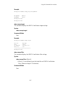
INSTALLING SOFTWARE UTILITIES
The installation CD includes documentation and software utilities to help you set
up and administer the wireless components of your network.
To view product documentation, select View the Documentation from the CD
Startup Menu and then select the item you want to view.
The software Tools and Utilities include:
3Com Wireless Infrastructure Device Manager. Use this tool to discover
access points and select devices for administrative changes.
3Com 3CDaemon Server Tool. This tool can act in four different capacities:
As a TFTP Server, necessary for firmware upgrades, and backup and restore
functions. Use this option if you do not have a TFTP server set up.
As a SysLog Server, which is necessary to view SysLog messages.
As an optional TFTP Client.
As an optional FTP Server.
To install a tool from the CD:
1
2
3
4
Power up the computer and put the 3Com CD in the CD-ROM drive.
The setup menu should appear when the CD autostarts. If no menu appears,
you can run the setup.exe startup program from the Windows Start menu.
For example, if your CD drive is the D drive: Start / Run / d:setup.exe.
From the CD startup menu, select Tools and Utilities.
Select the item you want to install and follow the instructions on the screen.
2-14
3
INITIAL CONFIGURATION
The Access Point 8760 offers a variety of management options, including a
web-based interface.
The initial configuration steps can be made through the web browser interface.
The access point requests an IP address via DHCP by default. If no response is
received from the DHCP server, then the access point uses the default address
169.254.2.1.
If the default AP configuration does not meet your network requirements, or if
you want to customize the settings for your own network, you can use these
tools to change the configuration:
1
Launch the 3Com Wireless Infrastructure Device Manager (Widman) utility
2
Directly connect to the device through it’s Ethernet port or console port
NETWORKS WITH A DHCP SERVER
If your network has a DHCP server, an IP address is automatically assigned to the
AP. It takes between one and two minutes for the Access Point to determine if
there is a DHCP server on the network. Use the 3Com Wireless Infrastructure
Device Manager (Widman) included on the 3Com Installation CD to locate the
Access Point on the network and view its IP address. After you determine the AP’s
IP address, you can enter that IP address into a web browser on a computer on
the same subnet to view the Access Point’s system status or change its
configuration.
NETWORKS WITHOUT A DHCP SERVER
If your network does not have a DHCP server, the Access Point uses a factory
assigned IP address (169.254.2.1). You can use that IP address to configure the
Access Point, or you can assign a new IP address to the Access Point. To verify that
the Access Point is using the default IP address assigned at the factory:
3-1
CHAPTER 3: INITIAL CONFIGURATION
1
Connect a computer directly to the Access Point using the supplied standard
Category 5 UTP Ethernet cable.
2
Enter the Access Point’s default IP address (169.254.2.1) into the computer’s
web browser. If the Configuration Management System starts, the Access
Point is using the factory assigned IP address. You can configure the Access
Point with the following login information:
Login name: admin
Password: password
If the Configuration Management System does not start, the Access Point is
on a different subnet than the computer. Install and start the 3Com Wireless
Infrastructure Device Manager to discover the Access Point’s IP address.
USING THE 3COM INSTALLATION CD
The 3Com Installation CD contains the following tools and utilities: 3Com
Wireless Infrastructure Device Manager-an administration tool that helps you
select 3Com wireless LAN devices and launch their configurations in your Web
browser.
LAUNCH THE 3COM WIRELESS INFRASTRUCTURE DEVICE
MANAGER (WIDMAN) UTILITY
1
Turn on the computer.
2
Insert the 3Com Installation CD into the CD-ROM drive.
The CD will Autorun. If it does not Autorun, you can start the setup menu
from the Windows Start menu. For example: Start > Run > d: setup.exe.
3
In the menu, click Tools and Utilities.
4
In the next screen, click the software you want to install.
5
Follow the on screen instructions to complete the installation.
Reboot the computer if prompted to do so.
LAUNCHING THE 3COM WIRELESS INTERFACE DEVICE MANAGER
To be able to configure the Access Point you need to run the Wireless Interface
Device Manager. Go to Start > Programs > 3Com Wireless > Wireless
Interface Device Manager.
If the device is working correctly the following screen should be seen.
3-2
Figure 8 Wireless Interface Device Manager
Click on the Properties button to see the following screen
Figure 9 Wireless Interface Device Manager - Properties
3-3
CHAPTER 3: INITIAL CONFIGURATION
Directly connect to the device through its Ethernet port or console port.
Follow the instructions below to login into the AP Configuration screen:
1
Load a web browser and enter <http://169.254.2.1>.
2
The Logon screen appears.
To log on to the Web interface:
1
Username, type admin (case sensitive).
2
Password, type password
3
Click Log On.
FIRST TIME ONLY
When you log in for the first time, you may be asked to select your country.
Choose your country from the drop-down list and then click Apply.
Click on the Setup Wizard for initial configuration.
For a new access point installation, the default WLAN Service Area (ESSID) is
3Com1 to 3Com4 for the 11a interface, and 3Com5 to 3Com8 for the 11b/g
interface, with no security set. Unless it detects a DHCP server on the network,
the access point uses Auto IP to assign an IP address of the form 169.254.2.1.
Use the 3Com Wireless Infrastructure Device Manager to locate 3Com Wireless
LAN devices and launch their configurations. When installing the device manager,
make sure the computer is connected to the same network as the device to be
configured. After installing and launching the device manager, select the device
to be configured from network tree and click Configure to launch the
configuration Web interface.
USING THE SETUP WIZARD
There are only a few basic steps you need to complete to connect the access
point to your corporate network and provide network access to wireless clients.
The Setup Wizard takes you through configuration procedures for the wireless
Service Set Identifier, the radio channel selection, IP configuration and basic
authentication for wireless clients.
The access point can be managed by any computer using a web browser (such as
Internet Explorer 5.0 or above). Enter the default IP address: http://169.254.2.1.
3-4
Using the Setup Wizard
NOTE: If you changed the default IP address via the command line interface above,
use that address instead of the one shown here.
Logging In – Enter the username “admin,” and password “password,” then
click LOGIN. For information on configuring a user name and password, see page
4-22.
Figure 10 Login Page
3-5
CHAPTER 3: INITIAL CONFIGURATION
The home page displays the Main Menu.
Figure 11 Home Page
Launching the Setup Wizard – To perform initial configuration, click Setup
Wizard on the home page, select the VAP you wish to configure, then click on the
[Next] button to start the process.
Figure 12 Setup Wizard - Start
3-6
Using the Setup Wizard
1
Service Set ID – Enter the service set identifier in the SSID box which all
wireless clients must use to associate with the access point. The SSID is case
sensitive and can consist of up to 32 alphanumeric characters.
Figure 13 Setup Wizard - Step 1
2
Radio Channel – You must enable radio communications for 802.11a and
802.11b/g, and set the operating radio channel.
NOTE: Available channel settings are limited by local regulations, which determine
the channels that are available. This User Guide shows channels and settings that
apply to North America (United States and Canada), with 13 channels available for
the 802.11a interface and 11 channels for the 802.11g interface. Other regions my
have different channels and settings available.
3-7
CHAPTER 3: INITIAL CONFIGURATION
Figure 14 Setup Wizard - Step 2
802.11a
Turbo Mode – If you select Enable, the access point will operate
in turbo mode with a data rate of up to 108 Mbps. Normal
mode support 13 channels, Turbo mode supports only 5
channels. (Default: Disabled)
802.11a Radio Channel – Set the operating radio channel
number. (Default: 60ch, 5.300 GHz when Auto Channel Select
is not enabled.)
Auto Channel Select – Select Enable for automatic radio
channel detection. (Default: Enabled)
802.11b/g
Turbo Mode - If you select Enable, the access point will operate in
turbo mode with a data rate of up to 108 Mbps. Normal mode support
11 channels, Turbo mode supports only 1 channel. (Default: Disabled)
802.11g Radio Channel - Set the operating radio channel number.
(Range 1-11; Default: 1 when Auto Channel Select is not enabled.
Auto Channel Select – Select Enable for automatic radio channel
detection. (Default: Enabled)
3-8
Using the Setup Wizard
3
IP Configuration – Either enable or disable Dynamic Host Configuration
Protocol (DHCP) for automatic IP configuration. If you disable DHCP, then
manually enter the IP address and subnet mask. If a management station
exists on another network segment, then you must enter the IP address for a
gateway that can route traffic between these segments. Then enter the IP
address for the primary and secondary Domain Name Servers (DNS) servers to
be used for host-name to IP address resolution.
Figure 15 Setup Wizard - Step 3
DHCP Client – With DHCP Client enabled, the IP address, subnet mask and
default gateway can be dynamically assigned to the access point by the
network DHCP server. (Default: Disabled)
NOTE: If there is no DHCP server on your network, then the access point will
automatically start up with its default IP address, 169.254.2.1.
4
Security – Set the Authentication Type to “Open” to allow open access
without authentication, or “Shared” to require authentication based on a
shared key. Enable encryption to encrypt data transmissions. To configure
other security features use the Advanced Setup menu as described in
Chapter 4.
3-9
CHAPTER 3: INITIAL CONFIGURATION
Figure 16 Setup Wizard - Step 4
Authentication Type – Use “Open System” to allow open access to all wireless
clients without performing authentication, or “Shared Key” to perform
authentication based on a shared key that has been distributed to all stations.
(Default: Open System)
WEP – Wired Equivalent Privacy is used to encrypt transmissions passing
between wireless clients and the access point. (Default: Disabled)
Shared Key Setup – If you select “Shared Key” authentication, enable WEP,
then configure the shared key by selecting 64-bit or 128-bit key type and
entering a hexadecimal or ASCII string of the appropriate length. The key can
be entered as alphanumeric characters or hexadecimal (0~9, A~F, e.g., D7 0A
9C 7F E5). (Default: 128 bit, hexadecimal key type)
64-Bit Manual Entry: The key can contain 10 hexadecimal digits, or 5
alphanumeric characters.
128-Bit Manual Entry: The key can contain 26 hexadecimal digits or 13
alphanumeric characters.
NOTE: All wireless devices must be configured with the same Key ID values to
communicate with the access point.
3-10
Using the Setup Wizard
5
Click Finish.
6
Click the OK button to complete the wizard.
Figure 17 Setup Wizard - Completed
3-11
CHAPTER 3: INITIAL CONFIGURATION
3-12
4
SYSTEM CONFIGURATION
Before continuing with advanced configuration, first complete the initial
configuration steps described in Chapter 4 to set up an IP address for the access
point.
The access point can be managed by any computer using a web browser (such as
Internet Explorer 5.0 or above). Enter the configured IP address of the access
point, or use the default address: http://169.254.2.1.
To log into the access point, enter the default user name “admin” and the
password “password,” then press “LOGIN.”
For a new access point installation, the default WLAN Service Area (ESSID) is
3Com and no security is set. Unless it detects a DHCP server on the network, the
access point uses Auto IP to assign an IP address of the form 169.254.2.1.
Use the 3Com Wireless Infrastructure Device Manager to locate 3Com Wireless
LAN devices and launch their configurations. When installing the device manager,
make sure the computer is connected to the same network as the device to be
configured. After installing and launching the device manager, select the device
to be configured from network tree and click Configure to launch the
configuration Web interface.
When the home page displays, click on Advanced Setup. The following page will
display.
4-1
CHAPTER 4: SYSTEM CONFIGURATION
Figure 18 Advanced Setup
The information in this chapter is organized to reflect the structure of the web
screens for easy reference. However, it is recommended that you configure a user
name and password as the first step under Administration to control
management access to this device (page 4-22).
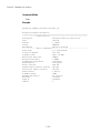
ADVANCED SETUP
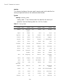
The Advanced Setup pages include the following options.
Table 2 Advanced Setup
Menu
Description
System
Page
Configures basic administrative and client access
4-4
Identification
Specifies the host name
4-4
TCP / IP Settings
Configures the IP address, subnet mask, gateway, and domain
name servers
4-5
RADIUS
Configures the RADIUS server for wireless client authentication
4-8
Authentication
Configures 802.1X client authentication, with an option for MAC
address authentication
4-9
Filter Control
Filters communications between wireless clients, access to the
management interface from wireless clients, and traffic matching
specific Ethernet protocol types
4-14
4-2
Advanced Setup
Menu
Description
Page
SNMP
Configures SNMP settings
4-18
Administration
Configures user name and password for management access;
upgrades software from local file, FTP or TFTP server; resets
configuration settings to factory defaults; and resets the access
point
4-22
WDS/STP Settings
Configures WDS bridging and Spanning Tree Protocol features
4-27
Syslog Set-up
Controls logging of error messages; sets the system clock via SNTP
server or manual configuration
4-33
Status
Displays information about the access point and wireless clients
4-59
AP Status
Displays configuration settings for the basic system and the
wireless interface
4-59
Station Status
Shows the wireless clients currently associated with the access
point
4-60
Event Logs
Shows log messages stored in memory
4-61
802.11a Interface
Configures the IEEE 802.11a interface
4-35
Radio Settings
Configures common radio signal parameters and other settings
for each VAP interface
4-36
Security
Enables each virtual access point (VAP) interface, sets the Service
Set Identifier (SSID), and configures wireless security
4-49
802.11b/g Interface
Configures the IEEE 802.11g interface
4-35
Radio Settings
Configures common radio signal parameters and other settings
for each VAP interface
4-42
Security
Enables each VAP interface, sets the SSID, and configures wireless
security
4-49
4-3
CHAPTER 4: SYSTEM CONFIGURATION
SYSTEM IDENTIFICATION
The system name for the access point can be left at its default setting. However,
modifying this parameter can help you to more easily distinguish different devices
in your network.
Figure 19 System Identification
System Name – An alias for the access point, enabling the device to be uniquely
identified on the network. (Default: Enterprise Wireless AP; Range: 1-32
characters)
4-4
TCP / IP Settings
TCP / IP SETTINGS
Configuring the access point with an IP address expands your ability to manage
the access point. A number of access point features depend on IP addressing to
operate.
NOTE: You can use the web browser interface to access IP addressing only if the
access point already has an IP address that is reachable through your network.
By default, the access point will be automatically configured with IP settings from
a Dynamic Host Configuration Protocol (DHCP) server. Use 3Com Wireless
Infrastructure Device Manager to discover or set the initial IP address of the unit.
WIDMAN will allow you to launch a web browser on the Access Point's web
management interface by selecting the Access Point and the configure button.
NOTE: If there is no DHCP server on your network, or DHCP fails, the access point
will automatically start up with a default IP address of 169.254.2.1.
Figure 20 TCP/IP Settings
4-5
CHAPTER 4: SYSTEM CONFIGURATION
DHCP Client (Enable) – Select this option to obtain the IP settings for the access
point from a DHCP (Dynamic Host Configuration Protocol) server. The IP address,
subnet mask, default gateway, and Domain Name Server (DNS) address are
dynamically assigned to the access point by the network DHCP server.
(Default: Enabled)
DHCP Client (Disable) – Select this option to manually configure a static address
for the access point.
IP Address: The IP address of the access point. Valid IP addresses consist of four
decimal numbers, 0 to 255, separated by periods.
Subnet Mask: The mask that identifies the host address bits used for routing to
specific subnets.
Default Gateway: The default gateway is the IP address of the router for the
access point, which is used if the requested destination address is not on the
local subnet.
If you have management stations, DNS, RADIUS, or other network servers
located on another subnet, type the IP address of the default gateway router in
the text field provided. Otherwise, leave the address as all zeros (0.0.0.0).
Primary and Secondary DNS Address: The IP address of Domain Name Servers
on the network. A DNS maps numerical IP addresses to domain names and can
be used to identify network hosts by familiar names instead of the IP addresses.
If you have one or more DNS servers located on the local network, type the IP
addresses in the text fields provided. Otherwise, leave the addresses as all zeros
(0.0.0.0).
Web Servers – Allows monitoring of the access point from a browser and secure
connection.
HTTP Server: Allows the access point to be monitored or configured from a
browser.
HTTP Port: Specifies the port to be used by the web browser interface.
HTTPS Server: Enables the secure HTTP server on the access point.
HTTPS Port: Specifies the UDP port number used for a secure HTTP connection
to the access pointís Web interface.
4-6
TCP / IP Settings
Figure 21 Smart Monitor
By enabling Smart Monitor (known as Link Integrity in the CLI) and setting a
target IP address, the AP will periodically (set by the ping interval) check to see if
the target address responds to pings. If it fails to respond to a ping after the
configured number of retries, it will disable both radios so that no clients can
connect to the AP.
This is used to disable the AP when it cannot not reach a critical network element
such as the RADIUS server, VPN Terminator, Mail Server etc.
Disable / Enable: Disables or enables a link check to a host device on the wired
network.
Target IP address: Specifies the IP address of a host device in the wired network.
Enable: Enables traffic between the host’s IP address and the AP.
Ping Interval: Specifies the time between each Ping sent to the link host.
(Range:300~30000 miliseconds; Default: 30 miliseconds)
Number of Retries allowed: Specifies the number of consecutive failed Ping
counts before the link is determined as lost. (Range:1~30; Default:6)
4-7
CHAPTER 4: SYSTEM CONFIGURATION
RADIUS
Remote Authentication Dial-in User Service (RADIUS) is an authentication protocol
that uses software running on a central server to control access to RADIUS-aware
devices on the network. An authentication server contains a database of user
credentials for each user that requires access to the network.
A primary RADIUS server must be specified for the access point to implement IEEE
802.1X network access control and Wi-Fi Protected Access (WPA) wireless
security. A secondary RADIUS server may also be specified as a backup should the
primary server fail or become inaccessible.
In addition, the configured RADIUS server can also act as a RADIUS Accounting
server and receive user-session accounting information from the access point.
RADIUS Accounting can be used to provide valuable information on user activity
in the network.
NOTE: This guide assumes that you have already configured RADIUS server(s) to
support the access point. Configuration of RADIUS server software is beyond the
scope of this guide, refer to the documentation provided with the RADIUS server
software.
Figure 22 RADIUS Authentication
Primary RADIUS Server Setup – Configure the following settings to use RADIUS
authentication on the access point.
IP Address: Specifies the IP address or host name of the RADIUS server.
4-8
Authentication
Port: The UDP port number used by the RADIUS server for authentication
messages. (Range: 1024-65535; Default: 1812)
Key: A shared text string used to encrypt messages between the access point
and the RADIUS server. Be sure that the same text string is specified on the
RADIUS server. Do not use blank spaces in the string. (Maximum length: 255
characters)
Timeout: Number of seconds the access point waits for a reply from the
RADIUS server before resending a request. (Range: 1-60 seconds; Default: 5)
Retransmit attempts: The number of times the access point tries to resend a
request to the RADIUS server before authentication fails. (Range: 1-30;
Default: 3)
NOTE: For the Timeout and Retransmit attempts fields, accept the default values
unless you experience problems connecting to the RADIUS server over the
network.
Secondary RADIUS Server Setup – Configure a secondary RADIUS server to
provide a backup in case the primary server fails. The access point uses the
secondary server if the primary server fails or becomes inaccessible. Once the
access point switches over to the secondary server, it periodically attempts to
establish communication again with primary server. If communication with the
primary server is re-established, the secondary server reverts to a backup role.
VLAN ID Format – A VLAN ID (a number between 1 and 4094) can be assigned to
each client after successful authentication using IEEE 802.1X and a central
RADIUS server. The user VLAN IDs must be configured on the RADIUS server for
each user authorized to access the network. VLAN IDs can be entered as
hexadecimal numbers or as ASCII strings.
AUTHENTICATION
Wireless clients can be authenticated for network access by checking their MAC
address against the local database configured on the access point, or by using a
database configured on a central RADIUS server. Alternatively, authentication can
be implemented using the IEEE 802.1X network access control protocol.
A client’s MAC address provides relatively weak user authentication, since MAC
addresses can be easily captured and used by another station to break into the
network. Using 802.1X provides more robust user authentication using user
names and passwords or digital certificates. You can configure the access point to
4-9
CHAPTER 4: SYSTEM CONFIGURATION
use both MAC address and 802.1X authentication, with client station MAC
authentication occurring prior to IEEE 802.1X authentication. However, it is better
to choose one or the other, as appropriate.
IEEE 802.1X is a standard framework for network access control that uses a
central RADIUS server for user authentication. This control feature prevents
unauthorized access to the network by requiring an 802.1X client application to
submit user credentials for authentication. The 802.1X standard uses the
Extensible Authentication Protocol (EAP) to pass user credentials (either digital
certificates, user names and passwords, or other) from the client to the RADIUS
server. Client authentication is then verified on the RADIUS server before the
access point grants client access to the network.
The 802.1X EAP packets are also used to pass dynamic unicast session keys and
static broadcast keys to wireless clients. Session keys are unique to each client and
are used to encrypt and correlate traffic passing between a specific client and the
access point. You can also enable broadcast key rotation, so the access point
provides a dynamic broadcast key and changes it at a specified interval.
The access point can also operate in a 802.1X supplicant mode. This enables the
access point itself to be authenticated with a RADIUS server using a configured
MD5 user name and password. This prevents rogue access points from gaining
access to the network.
Take note of the following points before configuring MAC address or 802.1X
authentication:
Use MAC address authentication for a small network with a limited number of
users. MAC addresses can be manually configured on the access point itself
without the need to set up a RADIUS server, but managing a large number of
MAC addresses across many access points is very cumbersome. A RADIUS
server can be used to centrally manage a larger database of user MAC
addresses.
Use IEEE 802.1X authentication for networks with a larger number of users and
where security is the most important issue. When using 802.1X authentication,
a RADIUS server is required in the wired network to centrally manage the
credentials of the wireless clients. It also provides a mechanism for enhanced
network security using dynamic encryption key rotation or W-Fi Protected
Access (WPA).
NOTE: If you configure RADIUS MAC authentication together with 802.1X,
RADIUS MAC address authentication is performed prior to 802.1X authentication.
If RADIUS MAC authentication succeeds, then 802.1X authentication is
performed. If RADIUS MAC authentication fails, 802.1X authentication is not
performed.
4-10
Authentication
Figure 23 Authentication
MAC Authentication – You can configure a list of the MAC addresses for wireless
clients that are authorized to access the network. This provides a basic level of
authentication for wireless clients attempting to gain access to the network. A
database of authorized MAC addresses can be stored locally on the access point
or remotely on a central RADIUS server.
(Default: Disabled)
Disabled: No checks are performed on an associating station’s MAC address.
4-11
CHAPTER 4: SYSTEM CONFIGURATION
Local MAC: The MAC address of the associating station is compared against
the local database stored on the access point. Use the Local MAC
Authentication section of this web page to set up the local database, and
configure all access points in the wireless network service area with the same
MAC address database.
RADIUS MAC: The MAC address of the associating station is sent to a
configured RADIUS server for authentication. When using a RADIUS
authentication server for MAC address authentication, the server must first be
configured on the RADIUS page (see “RADIUS” on page 4-8). The database of
MAC addresses and filtering policy must be defined in the RADIUS server. The
MAC address of the associating station is used for both the username and
password. For example, an associating station with a MAC address of
12-34-56-78-9A-BC would use a username and password of “12345678abc.”
The username and password sent to the server will use the format defined by
“radius-server radius-mac-format” (See “RADIUS Client” on page 5-64), which
has a default setting of “no-delimiter.”
NOTE: MAC addresses on the RADIUS server can be entered in four different
formats (see “radius-server radius-mac-format” on page 5-68).
You can enable 802.1X as optionally supported or as required to enhance the
security of the wireless network. (Default: Disable)
Disable: The access point does not support 802.1X authentication for any
wireless client. After successful wireless association with the access point, each
client is allowed to access the network.
Supported: The access point supports 802.1X authentication only for clients
initiating the 802.1X authentication process (i.e., the access point does not
initiate 802.1X authentication). For clients initiating 802.1X, only those
successfully authenticated are allowed to access the network. For those clients
not initiating 802.1X, access to the network is allowed after successful wireless
association with the access point. The 802.1X supported mode allows access
for clients not using WPA or WPA2 security.
Required: The access point enforces 802.1X authentication for all associated
wireless clients. If 802.1X authentication is not initiated by a client, the access
point will initiate authentication. Only those clients successfully authenticated
with 802.1X are allowed to access the network.
NOTE: If 802.1X is enabled on the access point, then RADIUS setup must be
completed (See “RADIUS” on page 8.)
4-12
Authentication
When 802.1X is enabled, the broadcast and session key rotation intervals can also
be configured.
Broadcast Key Refresh Rate: Sets the interval at which the broadcast keys are
refreshed for stations using 802.1X dynamic keying. (Range: 0-1440 minutes;
Default: 0 means disabled)
Session Key Refresh Rate: The interval at which the access point refreshes
unicast session keys for associated clients. (Range: 0-1440 minutes; Default: 0
means disabled)
802.1X Reauthentication Refresh Rate: The time period after which a
connected client must be re-authenticated. During the re-authentication
process of verifying the client’s credentials on the RADIUS server, the client
remains connected the network. Only if re-authentication fails is network
access blocked. (Range: 0-65535 seconds; Default: 0 means disabled)
802.1X Supplicant – The access point can also operate in a 802.1X supplicant
mode. This enables the access point itself to be authenticated with a RADIUS
server using a configured MD5 user name and password. This prevents rogue
access points from gaining access to the network.
Local MAC Authentication – Configures the local MAC authentication database.
The MAC database provides a mechanism to take certain actions based on a
wireless client’s MAC address. The MAC list can be configured to allow or deny
network access to specific clients.
System Default: Specifies a default action for all unknown MAC addresses (that
is, those not listed in the local MAC database).
• Deny: Blocks access for all MAC addresses except those listed in the local
database as “Allow.”
• Allow: Permits access for all MAC addresses except those listed in the local
database as “Deny.”
MAC Authentication Settings: Enters specified MAC addresses and permissions
into the local MAC database.
• MAC Address: Physical address of a client. Enter six pairs of hexadecimal
digits separated by hyphens; for example, 00-90-D1-12-AB-89.
• Permission: Select Allow to permit access or Deny to block access. If Delete
is selected, the specified MAC address entry is removed from the database.
• Update: Enters the specified MAC address and permission setting into the
local database.
MAC Authentication Table: Displays current entries in the local MAC database.
4-13
CHAPTER 4: SYSTEM CONFIGURATION
FILTER CONTROL
The access point can employ network traffic frame filtering to control access to
network resources and increase security. You can prevent communications
between wireless clients and prevent access point management from wireless
clients. Also, you can block specific Ethernet traffic from being forwarded by the
access point.
Figure 24 Filter Control
Inter Client STAs Communication Filter – Sets the global mode for
wireless-to-wireless communications between clients associated to Virtual AP
(VAP) interfaces on the access point. (Default: Prevent Inter and Intra VAP client
Communication)
Disable: All clients can communicate with each other through the access
point.
Prevent Intra VAP client communication: When enabled, clients associated
with a specific VAP interface cannot establish wireless communications with
each other. Clients can communicate with clients associated to other VAP
interfaces.
Prevent Inter and Intra VAP client communication: When enabled, clients
cannot establish wireless communications with any other client, either those
associated to the same VAP interface or any other VAP interface.
4-14
Filter Control
AP Management Filter – Controls management access to the access point from
wireless clients. Management interfaces include the web, Telnet, or SNMP.
(Default: Disabled)
Disabled: Allows management access from wireless clients.
Enabled: Blocks management access from wireless clients.
Uplink Port MAC Address Filtering Status – Prevents traffic with specified source
MAC addresses from being forwarded to wireless clients through the access
point. You can add a maximum of eight MAC addresses to the filter table.
(Default: Disabled)
MAC Address: Specifies a MAC address to filter, in the form xx-xx-xx-xx-xx-xx.
Permission: Adds or deletes a MAC address from the filtering table.
Ethernet Type Filter – Controls checks on the Ethernet type of all incoming and
outgoing Ethernet packets against the protocol filtering table. (Default: Disabled)
Disabled: Access point does not filter Ethernet protocol types.
Enabled: Access point filters Ethernet protocol types based on the configuration
of protocol types in the filter table. If the status of a protocol is set to “ON,”
the protocol is filtered from the access point.
NOTE: Ethernet protocol types not listed in the filtering table are always forwarded
by the access point.
4-15
CHAPTER 4: SYSTEM CONFIGURATION
VLAN
The access point can employ VLAN tagging support to control access to network
resources and increase security. VLANs separate traffic passing between the
access point, associated clients, and the wired network. There can be a VLAN
assigned to each associated client, a default VLAN for each VAP (Virtual Access
Point) interface, and a management VLAN for the access point.
Note the following points about the access point’s VLAN support:
The management VLAN is for managing the access point through remote
management tools, such as the web interface, SSH, SNMP, or Telnet. The
access point only accepts management traffic that is tagged with the specified
management VLAN ID.
All wireless clients associated to the access point are assigned to a VLAN. If IEEE
802.1X is being used to authenticate wireless clients, specific VLAN IDs can be
configured on the RADIUS server to be assigned to each client. If a client is not
assigned to a specific VLAN or if 802.1X is not used, the client is assigned to
the default VLAN for the VAP interface with which it is associated. The access
point only allows traffic tagged with assigned VLAN IDs or default VLAN IDs to
access clients associated on each VAP interface.
When VLAN support is enabled on the access point, traffic passed to the wired
network is tagged with the appropriate VLAN ID, either an assigned client
VLAN ID, default VLAN ID, or the management VLAN ID. Traffic received from
the wired network must also be tagged with one of these known VLAN IDs.
Received traffic that has an unknown VLAN ID or no VLAN tag is dropped.
When VLAN support is disabled, the access point does not tag traffic passed to
the wired network and ignores the VLAN tags on any received frames.
NOTE: Before enabling VLAN tagging on the access point, be sure to configure the
attached network switch port to support tagged VLAN frames from the access
point’s management VLAN ID, default VLAN IDs, and other client VLAN IDs.
Otherwise, connectivity to the access point will be lost when you enable the VLAN
feature.
Using IEEE 802.1X and a central RADIUS server, up to 64 VLAN IDs can be
mapped to specific wireless clients, allowing users to remain within the same
VLAN as they move around a campus site. This feature can also be used to control
access to network resources from clients, thereby improving security.
4-16
Filter Control
A VLAN ID (1-4094) can be assigned to a client after successful IEEE 802.1X
authentication. The client VLAN IDs must be configured on the RADIUS server for
each user authorized to access the network. If a client does not have a configured
VLAN ID on the RADIUS server, the access point assigns the client to the
configured default VLAN ID for the VAP interface.
NOTE: When using IEEE 802.1X to dynamically assign VLAN IDs, the access point
must have 802.1X authentication enabled and a RADIUS server configured.
Wireless clients must also support 802.1X client software.
When setting up VLAN IDs for each user on the RADIUS server, be sure to use the
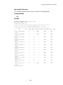
RADIUS attributes and values as indicated in the following table.
Number
RADIUS Attribute
Value
64
Tunnel-Type
VLAN (13)
65
Tunnel-Medium-Type
802
81
Tunnel-Private-Group-ID
VLANID
(1 to 4094 as hexadecimal or string)
VLAN IDs on the RADIUS server can be entered as hexadecimal digits or a string
(see “radius-server vlan-format” on page 5-69).
NOTE: The specific configuration of RADIUS server software is beyond the scope
of this guide. Refer to the documentation provided with the RADIUS server
software.
Figure 25 Filter Control - VLAN ID
VLAN – Enables or disables VLAN tagging support on the access point.
Management VLAN ID – The VLAN ID that traffic must have to be able to manage
the access point. (Range 1-4094; Default: 1)
4-17
CHAPTER 4: SYSTEM CONFIGURATION
SNMP
Simple Network Management Protocol (SNMP) is a communication protocol
designed specifically for managing devices on a network. Equipment commonly
managed with SNMP includes switches, routers and host computers. SNMP is
typically used to configure these devices for proper operation in a network
environment, as well as to monitor them to evaluate performance or detect
potential problems.
Managed devices supporting SNMP contain software, which runs locally on the
device and is referred to as an agent. A defined set of variables, known as
managed objects, is maintained by the SNMP agent and used to manage the
device. These objects are defined in a Management Information Base (MIB) that
provides a standard presentation of the information controlled by the agent.
SNMP defines both the format of the MIB specifications and the protocol used to
access this information over the network.
The access point includes an onboard agent that supports SNMP versions 1, 2c,
and 3 clients. This agent continuously monitors the status of the access point, as
well as the traffic passing to and from wireless clients. A network management
station can access this information using SNMP management software that is
compliant with MIB II. To implement SNMP management, the access point must
first have an IP address and subnet mask, configured either manually or
dynamically. Access to the onboard agent using SNMP v1 and v2c is controlled by
community strings. To communicate with the access point, the management
station must first submit a valid community string for authentication.
Access to the access point using SNMP v3 provides additional security features
that cover message integrity, authentication, and encryption; as well as
controlling notifications that are sent to specified user targets.
CONFIGURING SNMP AND TRAP MESSAGE PARAMETERS
The access point SNMP agent must be enabled to function (for versions 1, 2c, and
3 clients). Management access using SNMP v1 and v2c also requires community
strings to be configured for authentication. Trap notifications can be enabled and
sent to up to four management stations.
4-18
SNMP
Figure 26 SNMP
SNMP – Enables or disables SNMP management access and also enables the
access point to send SNMP traps (notifications). (Default: Disable)
Location – A text string that describes the system location. (Maximum length: 255
characters)
Contact – A text string that describes the system contact. (Maximum length: 255
characters)
Community Name (Read Only) – Defines the SNMP community access string that
has read-only access. Authorized management stations are only able to retrieve
MIB objects. (Maximum length: 23 characters, case sensitive; Default: public)
Community Name (Read/Write) – Defines the SNMP community access string that
has read/write access. Authorized management stations are able to both retrieve
and modify MIB objects. (Maximum length: 23 characters, case sensitive;
Default: private)
Trap Destination (1 to 4) – Enables recipients (up to four) of SNMP notifications.
Trap Destination IP Address – Specifies the recipient of SNMP notifications.
Enter the IP address or the host name. (Host Name: 1 to 63 characters, case
sensitive)
4-19
CHAPTER 4: SYSTEM CONFIGURATION
Trap Destination Community Name – The community string sent with the
notification operation. (Maximum length: 23 characters, case sensitive;
Default: public)
Engine ID – Sets the engine identifier for the SNMPv3 agent that resides on the
access point. This engine protects against message replay, delay, and redirection.
The engine ID is also used in combination with user passwords to generate the
security keys for authenticating and encrypting SNMPv3 packets. A default
engine ID is automatically generated that is unique to the access point. (Range:
10 to 64 hexadecimal characters)
NOTE: If the local engine ID is deleted or changed, all SNMP users will be cleared.
All existing users will need to be re-configured. If you want to change the default
engine ID, change it first before configuring other SNMP v3 parameters.
Figure 27 Trap Confiiguration
Trap Configuration – Allows selection of specific SNMP notifications to send. The
following items are available:
sysSystemUp - The access point is up and running.
sysSystemDown - The access point is about to shutdown and reboot.
sysRadiusServerChanged - The access point has changed from the primary
RADIUS server to the secondary, or from the secondary to the primary.
dot11StationAssociation - A client station has successfully associated with the
access point.
dot11StationReAssociation - A client station has successfully re-associated with
the access point.
dot11StationAuthentication - A client station has been successfully
authenticated.
dot11StationRequestFail - A client station has failed association, re-association,
or authentication.
dot11InterfaceGFail - The 802.11b interface has failed.
4-20
SNMP
dot11InterfaceAFail - The 802.11a or 802.11g interface has failed.
dot1xMacAddrAuthSuccess - A client station has successfully authenticated its
MAC address with the RADIUS server.
dot1xMacAddrAuthFail - A client station has failed MAC address
authentication with the RADIUS server.
dot1xAuthNotInitiated - A client station did not initiate 802.1X authentication.
dot1xAuthSuccess - A 802.1X client station has been successfully
authenticated by the RADIUS server.
dot1xAuthFail - A 802.1X client station has failed RADIUS authentication.
localMacAddrAuthSuccess - A client station has successfully authenticated its
MAC address with the local database on the access point.
localMacAddrAuthFail - A client station has failed authentication with the local
MAC address database on the access point.
sntpServerFail - The access point has failed to set the time from the configured
SNTP server.
CONFIGURING SNMPV3 USERS
The access point allows up to 10 SNMP v3 users to be configured. Each user must
be defined by a unique name, assigned to one of three pre-defined security
groups, and configured with specific authentication and encryption settings.
Figure 28 Configuring SNMPv3 Users
User – The SNMPv3 user name. (32 characters maximum)
Group – The SNMPv3 group name. (Options: RO, RWAuth, or RWPriv; Default:
RO)
RO – Read-only access.
RWAuth – Read/write access with user authentication.
RWPriv – Read/write access with both user authentication and data encryption.
Auth Type – The authentication type used for the SNMP user; either MD5 or
none. When MD5 is selected, enter a password in the corresponding Passphrase
field.
Priv Type – The data encryption type used for the SNMP user; either DES or none.
When DES is selected, enter a key in the corresponding Passphrase field.
4-21
CHAPTER 4: SYSTEM CONFIGURATION
Passphrase – The password or key associated with the authentication and privacy
settings. A minimum of eight plain text characters is required.
Action – Click the Add button to add a new user to the list. Click the edit button
to change details of an existing user. Click the Del button to remove a user from
the list.
NOTE: Users must be assigned to groups that have the same security levels. For
example, a user who has “Auth Type” and “Priv Type” configured to MD5 and DES
respectively (that it, uses both authentication and data encryption) must be
assigned to the RWPriv group. If this same user were instead assigned to the
read-only (RO) group, the user would not be able to access the database.
ADMINISTRATION
CHANGING THE PASSWORD
Management access to the web and CLI interface on the access point is
controlled through a single user name and password. You can also gain additional
access security by using control filters (see “Filter Control” on page 4-14).
To protect access to the management interface, you need to configure an
Administrator’s user name and password as soon as possible. If the user name
and password are not configured, then anyone having access to the access point
may be able to compromise access point and network security. Once a new
Administrator has been configured, you can delete the default “admin” user
name from the system.
NOTE: Pressing the Reset button on the back of the access point for more than
10 seconds resets the user name and password to the factory defaults. For this
reason, we recommend that you protect the access point from physical access by
unauthorized persons.
4-22
Administration
Figure 29 Administration
Username – The name of the user. The default name is “admin.” (Length: 3-16
characters, case sensitive)
New Password – The password for management access. (Length: 3-16 characters,
case sensitive)
Confirm New Password – Enter the password again for verification.
TELNET AND SSH SETTINGS
Telnet is a remote management tool that can be used to configure the access
point from anywhere in the network. However, Telnet is not secure from hostile
attacks. The Secure Shell (SSH) can act as a secure replacement for Telnet. The
SSH protocol uses generated public keys to encrypt all data transfers passing
between the access point and SSH-enabled management station clients and
ensures that data traveling over the network arrives unaltered. Clients can then
securely use the local user name and password for access authentication.
Note that SSH client software needs to be installed on the management station to
access the access point for management via the SSH protocol.
NOTE: The access point supports only SSH version 2.0.
NOTE: After boot up, the SSH server needs about two minutes to generate host
encryption keys. The SSH server is disabled while the keys are being generated.
Figure 30 Telnet and SSH Settings
4-23
CHAPTER 4: SYSTEM CONFIGURATION
Telnet Server: Enables or disables the Telnet server. (Default: Disabled)
SSH Server: Enables or disables the SSH server. (Default: Enabled)
SSH Port Number: Sets the UDP port for the SSH server. (Range: 1-65535;
Default: 22)
UPGRADING FIRMWARE
You can upgrade new access point software from a local file on the management
workstation, or from an TFTP server. New software may be provided periodically
from your distributor.
After upgrading new software, you must reboot the access point to implement
the new code. Until a reboot occurs, the access point will continue to run the
software it was using before the upgrade started. Also note that new software
that is incompatible with the current configuration automatically restores the
access point to the factory default settings when first activated after a reboot.
4-24
Administration
Figure 31 Firmware Upgrade
Before upgrading new software, verify that the access point is connected to the
network and has been configured with a compatible IP address and subnet mask.
If you need to download from an FTP or TFTP server, take the following additional
steps:
Obtain the IP address of the FTP or TFTP server where the access point software
is stored.
4-25
CHAPTER 4: SYSTEM CONFIGURATION
If upgrading from an FTP server, be sure that you have an account configured
on the server with a user name and password.
If VLANs are configured on the access point, determine the VLAN ID with which
the FTP or TFTP server is associated, and then configure the management
station, or the network port to which it is attached, with the same VLAN ID. If
you are managing the access point from a wireless client, the VLAN ID for the
wireless client must be configured on a RADIUS server.
Current version – Version number of runtime code.
Firmware Upgrade Local – Downloads an operation code image file from the web
management station to the access point using HTTP. Use the Browse button to
locate the image file locally on the management station and click Start Upgrade
to proceed.
New firmware file: Specifies the name of the code file on the server. The device
will only accept firmware files named “3Com-img.bin”.
Firmware Upgrade Remote – Downloads an operation code image file from a
specified remote FTP or TFTP server. After filling in the following fields, click Start
Upgrade to proceed.
New firmware file: Specifies the name of the code file on the server. The
firmware file must be named “3com-img.bin”.
IP Address: IP address or host name of the TFTP server.
Configuration File Backup/Restore – Uploads the current access point
configuration file to a specified remote TFTP server. A configuration file can also
be downloaded to the access point to restore a specific configuration.
Config file: Specifies the name of the configuration file. A path on the server
can be specified using “/” in the name, providing the path already exists; for
example, “myfolder/syscfg.” Other than to indicate a path, the file name must
not contain any slashes (\ or /), the leading letter cannot be a period (.), and the
maximum length for file names on the TFTP server is 255 characters. (Valid
characters: A-Z, a-z, 0-9, “.”, “-”, “_”)
IP Address: IP address or host name of the TFTP server.
Restore Factory Settings – Click the Restore button to reset the configuration
settings for the access point to the factory defaults and reboot the system. Note
that all user configured information will be lost. You will have to re-enter the
default user name (admin) to re-gain management access to this device.
Reboot Access Point – Click the Reset button to reboot the system.
4-26
WDS and Spanning Tree Settings
NOTE: If you have upgraded system software, then you must reboot the access
point to implement the new operation code. New software that is incompatible
with the current configuration automatically restores the access point to default
values when first activated after a reboot.
WDS AND SPANNING TREE SETTINGS
Each access point radio interface can be configured to operate in a bridge or
repeater mode, which allows it to forward traffic directly to other access point
units. To set up bridge links between access point units, you must configure the
wireless Distribution System (WDS) forwarding table by specifying the wireless
MAC address of all units to which you want to forward traffic. Up to six WDS
bridge or repeater links can be specified for each unit in the wireless bridge
network.
The Spanning Tree Protocol (STP) can be used to detect and disable network
loops, and to provide backup links between bridges. This allows a wireless bridge
to interact with other bridging devices (that is, an STP-compliant switch, bridge or
router) in your network to ensure that only one route exists between any two
stations on the network, and provide backup links which automatically take over
when a primary link goes down.
4-27
CHAPTER 4: SYSTEM CONFIGURATION
Figure 32 WDS and Spanning Tree Settings
4-28
WDS and Spanning Tree Settings
WDS Bridge – Up to six WDS bridge or repeater links (MAC addresses) per radio
interface can be specified for each unit in the wireless bridge network. One unit
only must be configured as the “root bridge” in the wireless network. The root
bridge is the unit connected to the main core of the wired LAN. Other bridges
need to specify one “Parent” link to the root bridge or to a bridge connected to
the root bridge. The other five WDS links are available as “Child” links to other
bridges.
Bridge Role – Each radio interface can be set to operate in one of the following
four modes: (Default: AP)
• AP (Access Point): Operates as an access point for wireless clients, providing
connectivity to a wired LAN.
• Bridge: Operates as a bridge to other access points. The “Parent” link to the
root bridge must be configured. Up to five other “Child” links are available
to other bridges.
• Repeater: Operates as a wireless repeater, extending the range for remote
wireless clients and connecting them to the root bridge. The “Parent” link
to the root bridge must be configured. In this mode, traffic is not forwarded
to the Ethernet port from the radio interface.
• Root Bridge: Operates as the root bridge in the wireless bridge network. Up
to six ”Child” links are available to other bridges in the network.
Bridge Parent – The physical layer address of the root bridge unit or the bridge
unit connected to the root bridge. (12 hexadecimal digits in the form
“xx-xx-xx-xx-xx-xx”)
Bridge Child – The physical layer address of other bridge units for which this
unit serves as the bridge parent or the root bridge. Note that the first entry
under the list of child nodes is reserved for the root bridge, and can only be
configured if the role is set to “Root Bridge.” (12 hexadecimal digits in the form
“xx-xx-xx-xx-xx-xx”)
4-29
CHAPTER 4: SYSTEM CONFIGURATION
Figure 33 Spanning Tree Protocol
Spanning Tree Protocol – STP uses a distributed algorithm to select a bridging
device (STP-compliant switch, bridge or router) that serves as the root of the
spanning tree network. It selects a root port on each bridging device (except for
the root device) which incurs the lowest path cost when forwarding a packet
4-30
WDS and Spanning Tree Settings
from that device to the root device. Then it selects a designated bridging device
from each LAN which incurs the lowest path cost when forwarding a packet from
that LAN to the root device. All ports connected to designated bridging devices
are assigned as designated ports. After determining the lowest cost spanning
tree, it enables all root ports and designated ports, and disables all other ports.
Network packets are therefore only forwarded between root ports and
designated ports, eliminating any possible network loops.
Once a stable network topology has been established, all bridges listen for Hello
BPDUs (Bridge Protocol Data Units) transmitted from the root bridge. If a bridge
does not get a Hello BPDU after a predefined interval (Maximum Age), the bridge
assumes that the link to the root bridge is down. This bridge will then initiate
negotiations with other bridges to reconfigure the network to reestablish a valid
network topology.
Bridge – Enables/disables STP on the wireless bridge or repeater.
(Default: Disabled)
Bridge Priority – Used in selecting the root device, root port, and designated
port. The device with the highest priority becomes the STP root device.
However, if all devices have the same priority, the device with the lowest MAC
address will then become the root device. (Note that lower numeric values
indicate higher priority.)
• Range: 0-65535
• Default: 32768
Bridge Max Age – The maximum time (in seconds) a device can wait without
receiving a configuration message before attempting to reconfigure. All device
ports (except for designated ports) should receive configuration messages at
regular intervals. Any port that ages out STP information (provided in the last
configuration message) becomes the designated port for the attached LAN. If
it is a root port, a new root port is selected from among the device ports
attached to the network. (Range: 6-40 seconds)
• Default: 20
• Minimum: The higher of 6 or [2 x (Hello Time + 1)].
• Maximum: The lower of 40 or [2 x (Forward Delay - 1)]
Bridge Hello Time – Interval (in seconds) at which the root device transmits a
configuration message. (Range: 1-10 seconds)
• Default: 2
• Minimum: 1
• Maximum: The lower of 10 or [(Max. Message Age / 2) -1]
4-31
CHAPTER 4: SYSTEM CONFIGURATION
Bridge Forwarding Delay – The maximum time (in seconds) this device waits
before changing states (i.e., discarding to learning to forwarding). This delay is
required because every device must receive information about topology
changes before it starts to forward frames. In addition, each port needs time to
listen for conflicting information that would make it return to a discarding
state; otherwise, temporary data loops might result. (Range: 4-30 seconds)
• Default: 15
• Minimum: The higher of 4 or [(Max. Message Age / 2) + 1]
• Maximum: 30
Link Path Cost – This parameter is used by the STP to determine the best path
between devices. Therefore, lower values should be assigned to ports attached
to faster media, and higher values assigned to ports with slower media. (Path
cost takes precedence over port priority.)
• Range: 1-65535
• Default: Ethernet interface: 19; Wireless interface: 40
Link Port Priority – Defines the priority used for this port in the Spanning Tree
Protocol. If the path cost for all ports on a switch are the same, the port with
the highest priority (i.e., lowest value) will be configured as an active link in the
spanning tree. This makes a port with higher priority less likely to be blocked if
the Spanning Tree Protocol is detecting network loops. Where more than one
port is assigned the highest priority, the port with lowest numeric identifier will
be enabled.
• Default: 128
• Range: 0-240, in steps of 16
4-32
System Log
SYSTEM LOG
The access point can be configured to send event and error messages to a System
Log Server. The system clock can also be synchronized with a time server, so that
all the messages sent to the Syslog server are stamped with the correct time and
date.
Figure 34 System Log
ENABLING SYSTEM LOGGING
The access point supports a logging process that can control error messages
saved to memory or sent to a Syslog server. The logged messages serve as a
valuable tool for isolating access point and network problems.
System Log Setup – Enables the logging of error messages. (Default: Disable)
Logging Level – Sets the minimum severity level for event logging.
(Default:Informational)
Logging Host – Enables the sending of log messages to a Syslog server host. Up
to four Syslog servers are supported on the access point. (Default: Disable)
Server Name / IP – Specifies a Syslog server name or IP address. (Default: 0.0.0.0)
SNTP Server – Enables the sending of log messages to a Syslog server host.
(Default: Disable)
Primary Server – The IP address the primary Syslog server. (Default: 0.0.0.0)
Secondary Server – The IP address the secondary Syslog server. (Default: 0.0.0.0)
4-33
CHAPTER 4: SYSTEM CONFIGURATION
Enter Time Zone – Sets the desired time zone + or - GMT.
Enable Daylight Saving – Adjusts the clock for summertime and wintertime.
The system allows you to limit the messages that are logged by specifying a
minimum severity level. The following table lists the error message levels from the
most severe (Emergency) to least severe (Debug). The message levels that are
logged include the specified minimum level up to the Emergency level.
Table 3 Logging Levels
Error Level
Description
Emergency
System unusable
Alerts
Immediate action needed
Critical
Critical conditions (e.g., memory allocation, or free memory error - resource
exhausted)
Error
Error conditions (e.g., invalid input, default used)
Warning
Warning conditions (e.g., return false, unexpected return)
Notice
Normal but significant condition, such as cold start
Informational
Informational messages only
Debug
Debugging messages
NOTE: The access point error log can be viewed using the Event Logs window in
the Status section (page 4-61). The Event Logs window displays the last 128
messages logged in chronological order, from the newest to the oldest. Log
messages saved in the access point’s memory are erased when the device is
rebooted.
CONFIGURING SNTP
Simple Network Time Protocol (SNTP) allows the access point to set its internal
clock based on periodic updates from a time server (SNTP or NTP). Maintaining an
accurate time on the access point enables the system log to record meaningful
dates and times for event entries. If the clock is not set, the access point will only
record the time from the factory default set at the last bootup.
The access point acts as an SNTP client, periodically sending time synchronization
requests to specific time servers. You can configure up to two time server IP
addresses. The access point will attempt to poll each server in the configured
sequence.
SNTP Server – Configures the access point to operate as an SNTP client. When
enabled, at least one time server IP address must be specified.
Primary Server: The IP address of an SNTP or NTP time server that the access
point attempts to poll for a time update.
4-34
Radio Interface
Secondary Server: The IP address of a secondary SNTP or NTP time server. The
access point first attempts to update the time from the primary server; if this
fails it attempts an update from the secondary server.
NOTE: The access point also allows you to disable SNTP and set the system clock
manually.
Set Time Zone – SNTP uses Coordinated Universal Time (or UTC, formerly
Greenwich Mean Time, or GMT) based on the time at the Earth’s prime meridian,
zero degrees longitude. To display a time corresponding to your local time, you
must indicate the number of hours your time zone is located before (east) or after
(west) UTC.
Enable Daylight Saving – The access point provides a way to automatically adjust
the system clock for Daylight Savings Time changes. To use this feature you must
define the month and date to begin and to end the change from standard time.
During this period the system clock is set back by one hour.
RADIO INTERFACE
The IEEE 802.11a and 802.11g interfaces include configuration options for radio
signal characteristics and wireless security features. The configuration options are
nearly identical, and are therefore both covered in this section of the manual.
The access point can operate in three modes, IEEE 802.11a only, 802.11b/g only,
or a mixed 802.11a/b/g mode. Also note that 802.11g is backward compatible
with 802.11b. These interfaces are configured independently under the following
web pages:
802.11a Interface
802.11b/g Interface
Each radio supports up to four virtual access point (VAP) interfaces numbered 1to
4. Each VAP functions as a separate access point, and can be configured with its
own Service Set Identification (SSID) and security settings. However, most radio
signal parameters apply to all four VAP interfaces.
The VAPs function similar to a VLAN, with each VAP mapped to its own VLAN ID.
Traffic to specific VAPs can be segregated based on user groups or application
traffic.
4-35
CHAPTER 4: SYSTEM CONFIGURATION
NOTE: The 8760 Access Point ships from the factory enabled only for channels
allowed in the US/Canada. If you live in an area where additional channels are
allowed, go to the 3Com web site (http://www.3com.com) and download the
latest software that will allow additional channels in your country.
802.11A INTERFACE
The IEEE 802.11a interface operates within the 5 GHz band, at up to 54 Mbps in
normal mode or up to 108 Mbps in Turbo mode.
First configure the radio settings that apply to the individual VAPs (Virtual Access
Point) and the common radio settings that apply to the overall system. After you
have configured the radio settings, go to the Security page under the 802.11a
Interface (See “Security” on page 49.), enable the radio service for any of the VAP
interfaces, and then set an SSID to identify the wireless network service provided
by each VAP. Remember that only clients with the same SSID can associate with a
VAP.
NOTE: You must first select a country before the wireless interfaces are enabled.
Configuring Radio Settings
To configure VAP radio settings, select the Radio Settings page.
Figure 35 Radio Settings A
Radio Status – Displays if the radio is enabled or disabled for this VAP.
NOTE: You must first enable VAP interface 1 before you can enable other VAP
interfaces.
4-36
Radio Interface
SSID – The name of the basic service set provided by a VAP interface. Clients that
want to connect to the network through the access point must set their SSID to
the same as that of an access point VAP interface. (Default: 3Com1 to 3Com4 for
802.11a, 3Com5 to 3Com8 for 802.11b/g; Range: 1-32 characters)
Default VLAN ID – The VLAN ID assigned to wireless clients associated to the VAP
interface that are not assigned to a specific VLAN by RADIUS server configuration.
(Default: 1)
Closed System – When enabled, the VAP interface does not include its SSID in
beacon messages. Nor does it respond to probe requests from clients that do not
include a fixed SSID. (Default: Disable)
Maximum Associations – This command configures the maximum number of
clients that can be associated with the access point at the same time.
Authentication Timeout Interval – The time within which the client should finish
authentication before authentication times out. (Range: 5-60 minutes; Default:
60 minutes)
Association Timeout Interval – The idle time interval (when no frames are sent)
after which a client is disassociated from the VAP interface. (Range: 5-60 minutes;
Default: 30 minutes)
4-37
CHAPTER 4: SYSTEM CONFIGURATION
CONFIGURING COMMON RADIO SETTINGS
To configure common radio settings, select the Radio Settings page, and scroll
down to below the VAP radio settings.
Figure 36 Radio Settings A
Country Code – The current country code setting. This setting restricts operation
of the access point to radio channels and transmit power levels permitted for
wireless networks in the specified country.
Description – Adds a comment or description to the wireless interface. (Range:
1-80 characters)
Turbo Mode – The normal 802.11a wireless operation mode provides connections
up to 54 Mbps. Turbo Mode is an enhanced mode (not regulated in IEEE 802.11a)
that provides a higher data rate of up to 108 Mbps. Enabling Turbo Mode allows
the access point to provide connections up to 108 Mbps. (Default: Disabled)
4-38
Radio Interface
NOTE: In normal mode, the access point provides a channel bandwidth of 20
MHz, and supports the maximum number of channels permitted by local
regulations (e.g., 13 channels for the United States). In Turbo Mode, the channel
bandwidth is increased to 40 MHz to support the increased data rate. However,
this reduces the number of channels supported (e.g., 5 channels for the United
States).
NOTE: .Check your country’s regulations to see if Turbo Mode is allowed.
Super Mode – The Atheros proprietary Super A performance enhancements are
supported by the access point. These enhancements include bursting,
compression, and fast frames. Maximum throughput ranges between 40 to 60
Mbps for connections to Atheros-compatible clients. (Default: Disabled)
Auto Channel Select – Enables the access point to automatically select an
unoccupied radio channel. (Default: Enabled)
NOTE: Check your country’s regulations to see if Auto Channel can be disabled.
Radio Channel – The radio channel that the access point uses to Normal Mode
communicate with wireless clients. When multiple access points
are deployed in the same area, set the channel on neighboring
access points at least four channels apart to avoid interference
with each other. For example, in the United States you can
deploy up to four access points in the same area (e.g., channels
36, 56, 149, 165). Also note that the channel for wireless
clients is automatically set to the same as that used by the
access point to which it is linked. (Default: Channel 60 for
normal mode, and channel 42 for Turbo mode)
Antenna ID – Selects the antenna to be used by the access
Turbo Mode
point; either the included diversity antennas or an optional
external antenna. The optional external antennas that are
certified for use with the access point are listed in the
drop-down menu. Selecting the correct antenna ID ensures that
the access point's radio transmissions are within regulatory
power limits for the country of operation. (Default: 3Com
Integrated Antenna)
4-39
CHAPTER 4: SYSTEM CONFIGURATION
NOTE: The Antenna ID must be selected in conjunction with the Output Antenna
to configure proper use of any of the antenna options.
Output Antenna – Selects the use of both fixed antennas operating in diversity
mode or a single antenna. (Default: Diversity)
Both: The radio uses both antennas in a diversity system. Select this method
when the Antenna ID is set to “3Com Integrated Antenna” to use the access
point's integrated antennas.
Right: The radio only uses the antenna on the right side (the side closest to the
access point LEDs). Select this method when using an optional external antenna
that is connected to the right antenna connector.
Left: The radio only uses the antenna on the left side (the side farthest from the
access point LEDs). Select this method when using an optional external antenna
that is connected to the left antenna connector.
Transmit Power – Adjusts the power of the radio signals transmitted from the
access point. The higher the transmission power, the farther the transmission
range. Power selection is not just a trade off between coverage area and
maximum supported clients. You also have to ensure that high-power signals do
not interfere with the operation of other radio devices in the service area.
(Options: 100%, 50%, 25%, 12%, minimum; Default: 100%)
NOTE: When operating the access point using 5 GHz channels in a European
Community country, the end user and installer are obligated to operate the device
in accordance with European regulatory requirements for Transmit Power Control
(TPC).
Maximum Transmit Data Rate – The maximum data rate at which the access point
transmits unicast packets on the wireless interface. The maximum transmission
distance is affected by the data rate. The lower the data rate, the longer the
transmission distance. (Options: 6, 9, 12, 18, 24, 36, 48, and 54 for 802.11a; 1,
2, 5.5, 6, 9, 11, 12, 18, 24, 36, 48, and 54 for 802.11b/g; Default: 54 Mbps)
Maximum Multicast Data Rate – The maximum data rate at which the access
point transmits multicast and broadcast packets on the wireless interface.
(Options: 24, 12, 6 Mbps; Default: 6 Mbps for 802.11a; 1, 2, 5.5, 11, Default
5.5 Mbps for 802.11b/g)
Beacon Interval – The rate at which beacon signals are transmitted from the
access point. The beacon signals allow wireless clients to maintain contact with
the access point. They may also carry power-management information.
(Range: 20-1000 TUs; Default: 100 TUs)
4-40
Radio Interface
Delivery Traffic Indication Message (DTIM) – The rate at which stations in sleep
mode must wake up to receive broadcast/multicast transmissions.
The DTIM interval indicates how often the MAC layer forwards
broadcast/multicast traffic, which is necessary to wake up stations that are using
Power Save mode. The default value of 1 indicates that the access point will save
all broadcast/multicast frames for the Basic Service Set (BSS) and forward them
after every beacon. Using smaller DTIM intervals delivers broadcast/multicast
frames in a more timely manner, causing stations in Power Save mode to wake up
more often and drain power faster. Using higher DTIM values reduces the power
used by stations in Power Save mode, but delays the transmission of
broadcast/multicast frames.
(Range: 1-255 beacons; Default: 1 beacon)
Fragment Length (256~2346)– Configures the minimum packet size that can be
fragmented when passing through the access point. Fragmentation of the PDUs
(Package Data Unit) can increase the reliability of transmissions because it
increases the probability of a successful transmission due to smaller frame size. If
there is significant interference present, or collisions due to high network
utilization, try setting the fragment size to send smaller fragments. This will speed
up the retransmission of smaller frames. However, it is more efficient to set the
fragment size larger if very little or no interference is present because it requires
overhead to send multiple frames. (Range: 256-2346 bytes; Default: 2346 bytes)
RTS Threshold – Sets the packet size threshold at which a Request to Send (RTS)
signal must be sent to a receiving station prior to the sending station starting
communications. The access point sends RTS frames to a receiving station to
negotiate the sending of a data frame. After receiving an RTS frame, the station
sends a CTS (clear to send) frame to notify the sending station that it can start
sending data.
If the RTS threshold is set to 0, the access point always sends RTS signals. If set to
2347, the access point never sends RTS signals. If set to any other value, and the
packet size equals or exceeds the RTS threshold, the RTS/CTS (Request to Send /
Clear to Send) mechanism will be enabled.
The access points contending for the medium may not be aware of each other.
The RTS/CTS mechanism can solve this “Hidden Node Problem.” (Range: 0-2347
bytes: Default: 2347 bytes)
4-41
CHAPTER 4: SYSTEM CONFIGURATION
802.11B/G INTERFACE
The IEEE 802.11g standard operates within the 2.4 GHz band at up to 54 Mbps.
Also note that because the IEEE 802.11g standard is an extension of the IEEE
802.11b standard, it allows clients with 802.11b wireless network cards to
associate to an 802.11g access point.
First configure the radio settings that apply to the individual VAPs (Virtual Access
Point) and the common radio settings that apply to all of the 802.11g interfaces.
After you have configured the radio settings, enable the radio service for any of
the VAP interfaces, and then set an SSID to identify the wireless network service
provided by each VAP. Remember that only clients with the same SSID can
associate with a VAP.
NOTE: You must first select a country of operation before interfaces can be
enabled.
Most of the 802.11g commands are identical to those used by the 802.11a
interface. For information on the these commands, refer to the following
sections:
“Configuring Radio Settings” on page 4-36
“Configuring Common Radio Settings” on page 4-38
“Configuring Wi-Fi Multimedia” on page 4-44
Only the radio settings specific to the 802.11g interface are included in this
section. To configure the 802.11g radio settings, select the Radio Settings page.
4-42
Radio Interface
Figure 37 Radio Settings B/G
Client Access Mode – Selects the operating mode for the 802.11g wireless
interface. (Default: 802.11b+g)
802.11b+g: Both 802.11b and 802.11g clients can communicate with the
access point (up to 54 Mbps).
802.11b only: Both 802.11b and 802.11g clients can communicate with the
access point, but 802.11g clients can only transfer data at 802.11b standard
rates (up to 11 Mbps).
802.11g only: Only 802.11g clients can communicate with the access point (up
to 54 Mbps).
Turbo Mode – The normal 802.11g wireless operation mode provides connections
up to 54 Mbps. Turbo Mode is an enhanced proprietary mode (Atheros 802.11g
Turbo) that provides a higher data rate of up to 108 Mbps. Enabling Turbo mode
allows the access point to provide connections up to 108 Mbps to
Atheros-compatible clients.
NOTE: In normal mode, the access point supports the maximum number of
channels permitted by local regulations (e.g., 11 channels for the United States). In
Turbo mode, channel bonding is used to provide the increased data rate. However,
this reduces the number of channels available to one (Channel 6).
4-43
CHAPTER 4: SYSTEM CONFIGURATION
Super Mode – The Atheros proprietary Super G performance enhancements
are supported by the access point. These enhancements include bursting,
compression, fast frames and dynamic turbo. Maximum throughput ranges
between 40 to 60 Mbps for connections to Atheros-compatible clients.
(Default: Disabled)
Radio Channel – The radio channel that the access point uses to communicate
with wireless clients. When multiple access points are deployed in the same area,
set the channel on neighboring access points at least five channels apart to avoid
interference with each other. For example, in the United States you can deploy up
to three access points in the same area (e.g., channels 1, 6, 11). Also note that
the channel for wireless clients is automatically set to the same as that used by
the access point to which it is linked. (Range: 1-11; Default: 1)
Auto Channel Select – Enables the access point to automatically select an
unoccupied radio channel. (Default: Enabled)
Maximum Transmit Data Rate – The maximum data rate at which the
access point transmits unicast packets on the wireless interface. The
maximum transmission distance is affected by the data rate. The lower the
data rate, the longer the transmission distance. (Default: 54 Mbps)
Preamble Length – Sets the length of the signal preamble that is used at
the start of a data transmission. (Default: Long)
Short: Sets the preamble to short (96 microseconds). Using a short
preamble can increase data throughput.
Long: Sets the preamble to long (192 microseconds). Using a long
preamble ensures the access point can support all 802.11b and 802.11g
clients.
Auto: Sets the preamble according to the capability of clients that are currently
asscociated. Uses a short preamble (96 microseconds) if all associated clients
can support it, otherwise a long preamble is used. The access point can increase
data throughput when using a short preamble, but will only use a short
preamble if it determines that all associated clients support it.
CONFIGURING WI-FI MULTIMEDIA
Wireless networks offer an equal opportunity for all devices to transmit data from
any type of application. Although this is acceptable for most applications,
multimedia applications (with audio and video) are particularly sensitive to the
delay and throughput variations that result from this equal opportunity wireless
access method. For multimedia applications to run well over a wireless network, a
Quality of Service (QoS) mechanism is required to prioritize traffic types and
provide an enhanced opportunityî wireless access method.
4-44
Radio Interface
The access point implements QoS using the Wi-Fi Multimedia (WMM) standard.
Using WMM, the access point is able to prioritize traffic and optimize
performance when multiple applications compete for wireless network
bandwidth at the same time. WMM employs techniques that are a subset of the
developing IEEE 802.11e QoS standard and it enables the access point to inter
operate with both WMMenabled clients and other devices that may lack any
WMM functionality.
Access Categories – WMM defines four access categories (ACs): voice, video, best
effort, and background. These categories correspond to traffic priority levels and
are mapped to IEEE 802.1D priority tags. The direct mapping of the four ACs to
802.1D priorities is specifically intended to facilitate inter operability with other
wired network QoS policies. While the four ACs are specified for specific types of
traffic, WMM allows the priority levels to be configured to match any
network-wide QoS policy. WMM also specifies a protocol that access points can
use to communicate the configured traffic priority levels to QoS-enabled wireless
clients.
Table 4 WMM Access Categories
WMM Access Categories
Access
Category
WMM
Designation
Description
802.1D
Tags
AC_VO (AC3)
Voice
Highest priority, minimum delay.
Time-sensitive data such as VoIP (Voice
over IP) calls.
7, 6
AC_VI (AC2)
Video
High priority, minimum delay.
Time-sensitive data such as streaming
video.
5, 4
AC_BE (AC0)
Best Effort
Normal priority, medium delay and
throughput. Data only affected by long
delays. Data from applications or
devices that lack QoS capabilities.
0, 3
AC_BK (AC1)
Background
Lowest priority. Data with no delay or
throughput requirements, such as bulk
data transfers.
2, 1
WMM Operation – WMM uses traffic priority based on the four ACs; Voice,
Video, Best Effort, and Background. The higher the AC priority, the higher the
probability that data is transmitted.
When the access point forwards traffic, WMM adds data packets to four
independent transmit queues, one for each AC, depending on the 802.1D
priority tag of the packet. Data packets without a priority tag are always added to
the Best Effort AC queue. From the four queues, an internal “virtual” collision
4-45
CHAPTER 4: SYSTEM CONFIGURATION
resolution mechanism first selects data with the highest priority to be granted a
transmit opportunity. Then the same collision resolution mechanism is used
externally to determine which device has access to the wireless medium.
For each AC queue, the collision resolution mechanism is dependent on two
timing parameters:
AIFSN (Arbitration Inter-Frame Space Number), a number used to calculate the
minimum time between data frames
CW (Contention Window), a number used to calculate a random backoff time
After a collision detection, a backoff wait time is calculated. The total wait time is
the sum of a minimum wait time (Arbitration Inter-Frame Space, or AIFS)
determined from the AIFSN, and a random backoff time calculated from a value
selected from zero to the CW. The CW value varies within a configurable range. It
starts at CWMin and doubles after every collision up to a maximum value,
CWMax. After a successful transmission, the CW value is reset to its CWMin
value.
Figure 38 WMM Backoff Times
Time
CWMin
High Priority
CWMax
AIFS
Random Backoff
Minimum Wait Time
Random Wait Time
CWMin
Low Priority
CWMax
AIFS
Random Backoff
Minimum Wait Time
Random Wait Time
For high-priority traffic, the AIFSN and CW values are smaller. The smaller values
equate to less backoff and wait time, and therefore more transmit opportunities.
To configure WMM, select the Radio Settings page, and scroll down to the WMM
configuration settings.
4-46
Radio Interface
Figure 39 WMM Configuration
WMM – Sets the WMM operational mode on the access point. When enabled,
the parameters for each AC queue will be employed on the access point and QoS
capabilities are advertised to WMM-enabled clients. (Default: Support)
Disable: WMM is disabled.
Support: WMM will be used for any associated device that supports this
feature.
Devices that do not support this feature may still associate with the access
point.
Required: WMM must be supported on any device trying to associated with the
access point. Devices that do not support this feature will not be allowed to
associate with the access point.
WMM Acknowledge Policy – By default, all wireless data transmissions require
the sender to wait for an acknowledgement from the receiver. WMM allows the
acknowledgement wait time to be turned off for each Access Category (AC).
Although this increases data throughput, it can also result in a high number of
errors when traffic levels are heavy. (Default: Acknowledge)
WMM BSS Parameters – These parameters apply to the wireless clients.
WMM AP Parameters – These parameters apply to the access point.
logCWMin (Minimum Contention Window) – The initial upper limit of the
random backoff wait time before wireless medium access can be attempted. The
4-47
CHAPTER 4: SYSTEM CONFIGURATION
initial wait time is a random value between zero and the CWMin value. Specify
the CWMin value in the range 0-15 microseconds. Note that the CWMin value
must be equal or less than the CWMax value.
logCWMax (Maximum Contention Window) – The maximum upper limit of the
random backoff wait time before wireless medium access can be attempted. The
contention window is doubled after each detected collision up to the CWMax
value. Specify the CWMax value in the range 0-15 microseconds. Note that the
CWMax value must be greater or equal to the CWMin value.
AIFS (Arbitration Inter-Frame Space) – The minimum amount of wait time before
the next data transmission attempt. Specify the AIFS value in the range 0-15
microseconds.
TXOP Limit (Transmit Opportunity Limit) – The maximum time an AC transmit
queue has access to the wireless medium. When an AC queue is granted a
transmit opportunity, it can transmit data for a time up to the TxOpLimit. This
data bursting greatly improves the efficiency for high data-rate traffic. Specify a
value in the range 0-65535 microseconds.
Admission Control – The admission control mode for the access category. When
enabled, clients are blocked from using the access category. (Default: Disabled)
Key Type – See Wired Equivalent Privacy (WEP).
4-48
Security
SECURITY
The access point is configured by default as an “open system,” which broadcasts
a beacon signal including the configured SSID. Wireless clients with an SSID
setting of “any” can read the SSID from the beacon and automatically set their
SSID to allow immediate connection to the nearest access point.
To improve wireless network security, you have to implement two main functions:
Authentication: It must be verified that clients attempting to connect to the
network are authorized users.
Traffic Encryption: Data passing between the access point and clients must be
protected from interception and eavesdropping.
For a more secure network, the access point can implement one or a combination
of the following security mechanisms:
Wired Equivalent Privacy (WEP)
page 4-49
IEEE 802.1x
page 4-56
Wireless MAC address filtering
page 4-11
Wi-Fi Protected Access (WPA or WPA2) page 4-56
Both WEP and WPA security settings are configurable separately for each virtual
access point (VAP) interface. MAC address filtering, and RADIUS server settings
are global and apply to all VAP interfaces.
The security mechanisms that may be employed depend on the level of security
required, the network and management resources available, and the software
support provided on wireless clients.
A summary of wireless security considerations is listed in the following table.
Table 5 Wireless Security Considerations
Security
Mechanism
Client Support
Implementation Considerations
WEP
Built-in support on all 802.11a
and 802.11g devices
• Provides only weak security
• Requires manual key management
WEP over 802.1X
Requires 802.1X client support • Provides dynamic key rotation for improved WEP
in system or by add-in software
security
(support provided in Windows • Requires configured RADIUS server
2000 SP3 or later and Windows • 802.1X EAP type may require management of
XP)
digital certificates for clients and server
MAC Address
Filtering
Uses the MAC address of client • Provides only weak user authentication
network card
• Management of authorized MAC addresses
• Can be combined with other methods for
improved security
• Optionally configured RADIUS server
4-49
CHAPTER 4: SYSTEM CONFIGURATION
Security
Mechanism
Client Support
Implementation Considerations
WPA over 802.1X Requires WPA-enabled system
Mode
and network card driver
(native support provided in
Windows XP)
• Provides robust security in WPA-only mode
(i.e., WPA clients only)
• Offers support for legacy WEP clients, but with
increased security risk (i.e., WEP authentication
keys disabled)
• Requires configured RADIUS server
• 802.1X EAP type may require management of
digital certificates for clients and server
WPA PSK Mode
Requires WPA-enabled system
and network card driver
(native support provided in
Windows XP)
• Provides good security in small networks
• Requires manual management of pre-shared key
WPA2 with
802.1X
Requires WPA-enabled system • Provides the strongest security in WPA2-only
and network card driver (native
mode
support provided in Windows
• Provides robust security in mixed mode for WPA
XP)
and WPA2 clients
• Offers fast roaming for time-sensitive client
applications
• Requires configured RADIUS server
• 802.1X EAP type may require management of
digital certificates for clients and server
• Clients may require hardware upgrade to be
WPA2 compliant
WPA2 PSK Mode
Requires WPA-enabled system • Provides robust security in small networks
and network card driver (native • Requires manual management of pre-shared key
support provided in Windows
• Clients may require hardware upgrade to be
XP)
WPA2 compliant
NOTE: You must enable data encryption through the web in order to enable all
types of encryption (WEP, TKIP, or AES) in the access point.
The access point can simultaneously support clients using various different
security mechanisms. The configuration for these security combinations are
outlined in the following table. Note that MAC address authentication can be
configured independently to work with all security mechanisms and is indicated
separately in the table. Required RADIUS server support is also listed.
Table 6 Security Considerations
Client Security
Combination
Configuration Summarya
MAC
Authenticationb
RADIUS
Server
No encryption and no Authentication: Open System
Encryption: Disable
authentication
802.1x: Disable
Local, RADIUS, or
Disabled
Yesc
Static WEP only (with Enter 1 to 4 WEP keys
Select a WEP transmit key for the interface
or without shared
key authentication)
Authentication: Shared Key or Open System
Encryption: Enable
802.1x: Disable
Local, RADIUS, or
Disabled
Yesc
4-50
Security
Client Security
Combination
Configuration Summarya
MAC
Authenticationb
RADIUS
Server
Dynamic WEP
(802.1x) only
Authentication: Open System
Local, RADIUS, or
Encryption: Enable
Disabled
802.1x: Required
Set 802.1x key refresh and reauthentication rates
Yesc
802.1x WPA only
Authentication: WPA
Local only
Encryption: Enable
WPA Configuration: Required
Cipher Suite: TKIP
802.1x: Required
Set 802.1x key refresh and reauthentication rates
Yes
WPA Pre-Shared Key
only
Authentication: WPA-PSK
Encryption: Enable
WPA Configuration: Required
Cipher Configuration: TKIP
802.1x: Disable
WPA Pre-shared Key Type: Hexadecimal or
Alphanumeric
Enter a WPA Pre-shared key
No
Static and dynamic
(802.1x) WEP keys
Enter 1 to 4 WEP keys
Local, RADIUS, or
Select a WEP transmit key
Disabled
Authentication: Open System
Encryption: Enable
802.1x: Supported
Set 802.1x key refresh and reauthentication rates
Yes
Dynamic WEP and
802.1x WPA
Authentication: WPA
Local or Disabled
Encryption: Enable
WPA Configuration: Supported
Cipher Suite: WEP
802.1x: Required
Set 802.1x key refresh and reauthentication rates
Yes
Static and dynamic
(802.1x) WEP keys
and 802.1x WPA
Enter 1 to 4 WEP keys
Local or Disabled
Select a WEP transmit key
Authentication: WPA
Encryption: Enable
WPA Configuration: Supported
Cipher Suite: WEP
802.1x: Supported
Set 802.1x key refresh and reauthentication rates
Yes
802.1x WPA2 only
Authentication: WPA2
Local or Disabled
Encryption: Enable
WPA Configuration: Required
Cipher Suite: AES-CCMP
802.1x: Required
Set 802.1x key refresh and reauthentication rates
Yes
WPA2 Pre-Shared
Key only
Authentication: WPA2-PSK
Encryption: Enable
WPA Configuration: Required
Cipher Suite: AES-CCMP
802.1x: Disable
WPA Pre-shared Key Type: Hexadecimal or
Alphanumeric
Enter a WPA Pre-shared key
No
4-51
Local only
Local or Disabled
CHAPTER 4: SYSTEM CONFIGURATION
Client Security
Combination
802.1x WPA-WPA2
Mixed Mode
Configuration Summarya
MAC
Authenticationb
Authentication: WPA-WPA2-mixed
Local or Disabled
Encryption: Enable
WPA Configuration: Required
Cipher Suite: TKIP
802.1x: Required
Set 802.1x key refresh and reauthentication rates
WPA-WPA2 Mixed
Authentication: WPA-WPA2-PSK-mixed
Mode Pre-Shared Key Encryption: Enable
WPA Configuration: Required
Cipher Suite: TKIP
802.1x: Disable
WPA Pre-shared Key Type: Hexadecimal or
Alphanumeric
Enter a WPA Pre-shared key
Local or Disabled
RADIUS
Server
Yes
No
a The configuration summary does not include the set up for MAC authentication (see page 4-9) or
RADIUS server (see page 4-8).
b The configuration of RADIUS MAC authentication together with 802.1x WPA or WPA Pre-shared
Key is not supported.
NOTE: If you choose to configure RADIUS MAC authentication together with
802.1X, the RADIUS MAC address authentication occurs prior to 802.1X
authentication. Only when RADIUS MAC authentication succeeds is 802.1X
authentication performed. When RADIUS MAC authentication fails, 802.1X
authentication is not performed.
WIRED EQUIVALENT PRIVACY (WEP)
WEP provides a basic level of security, preventing unauthorized access to the
network, and encrypting data transmitted between wireless clients and the access
point. WEP uses static shared keys (fixed-length hexadecimal or alphanumeric
strings) that are manually distributed to all clients that want to use the network.
WEP is the security protocol initially specified in the IEEE 802.11 standard for
wireless communications. Unfortunately, WEP has been found to be seriously
flawed and cannot be recommended for a high level of network security. For
more robust wireless security, the access point provides Wi-Fi Protected Access
(WPA) for improved data encryption and user authentication.
Setting up shared keys enables the basic IEEE 802.11 Wired Equivalent Privacy
(WEP) on the access point to prevent unauthorized access to the network.
If you choose to use WEP shared keys instead of an open system, be sure to
define at least one static WEP key for user authentication and data encryption.
Also, be sure that the WEP shared keys are the same for each client in the wireless
network.
4-52
Security
Note that all clients share the same keys, which are used for user authentication
and data encryption. Up to four keys can be specified. These four keys are used
for all VAP interfaces on the same radio.
To set up WEP shared keys, click Radio Settings under 802.11a or 802.11b/g, then
select Authentication ‘Shared’. To use all other than WEP shared keys, select
Authentication ‘Open.’
The following example presumes that you have selected to opt for other methods
of encryption than WEP.
Figure 40 Authentication and Encryption
Authentication – Sets the access point to communicate as an open system that
accepts network access attempts from any client, or with clients using
pre-configured static shared keys. (Default: Open System)
Open System: If you don’t set up any other security mechanism on the access
point, the network has no protection and is open to all users. This is the default
setting.
Shared Key: Sets the access point to use WEP shared keys. If this option is
selected, you must configure at least one key on the access point and all clients.
NOTE: To use 802.1X on wireless clients requires a network card driver and
802.1X client software that supports the EAP authentication type that you want to
use. Windows 2000 SP3 or later and Windows XP provide 802.1X client support.
Windows XP also provides native WPA support. Other systems require additional
client software to support 802.1X and WPA.
4-53
CHAPTER 4: SYSTEM CONFIGURATION
Encryption – Enable or disable the access point to use data encryption (WEP, TKIP,
or AES). If this option is selected when using static WEP keys, you must configure
at least one key on the access point and all clients. (Default: Disabled)
NOTE: You must enable data encryption through the web or CLI in order to enable
all types of encryption (WEP, TKIP, or AES) in the access point.
Cipher Modes – Selects an encryption method for the global key used for
multicast and broadcast traffic, which is supported by all wireless clients.
AES: AES-CCMP is used as the multicast encryption cipher. AES-CCMP is the
standard encryption cipher required for WPA2.
TKIP: TKIP is used as the multicast encryption cipher.
WEP/TKIP: WEP is used as the multicast encryption cipher. You should select
WEP only when both WPA and WEP clients are supported.
Figure 41 WPA Key Management
WPA Key Management – Specifies the type of WPA encryption to use:
WPA authentication over 802.1x – Requires the use of 802.1x authentication.
WPA Pre-shared Key (PSK) – Requires that 802.1x authentication be disabled.
Key Type – Select the preferred method of entering WEP encryption keys on the
access point and enter up to four keys:
Hexadecimal: Enter keys as 10 hexadecimal digits (0-9 and A-F) for 64 bit keys,
26 hexadecimal digits for 128 bit keys, or 32 hexadecimal digits for 152 bit keys
(802.11a radio only). This is the default setting.
4-54
Security
Alphanumeric: Enter keys as 5 alphanumeric characters for 64 bit keys, 13
alphanumeric characters for 128 bit keys, or 16 alphanumeric characters for
152 bit keys (802.11a radio only).
Key – Selects the key number to use for encryption for each VAP interface. If
the clients have all four keys configured to the same values, you can change the
encryption key to any of the four settings without having to update the client
keys. (Default: Key 1)
Figure 42 WEP Keys
Client Types – Specifies the type of client to encrypt:
WEP and WPA clients – Both WEP and TKIP encryption are supported.
WPA clients only – All clients must support TKIP.
WEP clients only – All clients must support WEP.
WEP Configuration – Under open authentication it is still possible to configure
WEP keys.
Key Size – 64 Bit, 128 Bit, or 152 Bit key length. Note that the same size of
encryption key must be supported on all wireless clients. (Default: None)
Key Type – Select the preferred method of entering WEP encryption keys on the
access point and enter up to four keys:
4-55
CHAPTER 4: SYSTEM CONFIGURATION
• Hexadecimal: Enter keys as 10 hexadecimal digits (0-9 and A-F) for 64 bit
keys, 26 hexadecimal digits for 128 bit keys, or 32 hexadecimal digits for 152
bit keys (802.11a radio only). This is the default setting.
• Alphanumeric: Enter keys as 5 alphanumeric characters for 64 bit keys, 13
alphanumeric characters for 128 bit keys, or 16 alphanumeric characters for
152 bit keys (802.11a radio only).
Key – Selects the key number to use for encryption for each VAP interface. If the
clients have all four keys configured to the same values, you can change the
encryption key to any of the four settings without having to update the client
keys. (Default: Key 1)
NOTE: Key index and type must match that configured on the clients.
NOTE: In a mixed-mode environment with clients using static WEP keys and WPA,
select WEP transmit key index 2, 3, or 4. The access point uses transmit key index
1 for the generation of dynamic keys.
Wi-Fi Protected Access (WPA)
WPA employs a combination of several technologies to provide an enhanced
security solution for 802.11 wireless networks.
The access point supports the following WPA components and features:
IEEE 802.1X and the Extensible Authentication Protocol (EAP): WPA employs
802.1X as its basic framework for user authentication and dynamic key
management. The 802.1X client and RADIUS server should use an appropriate
EAP type—such as EAP-TLS (Transport Layer Security), EAP-TTLS (Tunneled TLS), or
PEAP (Protected EAP)—for strongest authentication. Working together, these
protocols provide “mutual authentication” between a client, the access point,
and a RADIUS server that prevents users from accidentally joining a rogue
network. Only when a RADIUS server has authenticated a user’s credentials will
encryption keys be sent to the access point and client.
NOTE: To implement WPA on wireless clients requires a WPA-enabled network
card driver and 802.1X client software that supports the EAP authentication type
that you want to use. Windows XP provides native WPA support, other systems
require additional software.
4-56
Security
Temporal Key Integrity Protocol (TKIP): WPA specifies TKIP as the data
encryption method to replace WEP. TKIP avoids the problems of WEP static keys
by dynamically changing data encryption keys. Basically, TKIP starts with a master
(temporal) key for each user session and then mathematically generates other
keys to encrypt each data packet. TKIP provides further data encryption
enhancements by including a message integrity check for each packet and a
re-keying mechanism, which periodically changes the master key.
WPA Pre-Shared Key Mode (WPA-PSK, WPA2-PSK): For enterprise deployment,
WPA requires a RADIUS authentication server to be configured on the wired
network. However, for small office networks that may not have the resources to
configure and maintain a RADIUS server, WPA provides a simple operating mode
that uses just a pre-shared password for network access. The Pre-Shared Key
mode uses a common password for user authentication that is manually entered
on the access point and all wireless clients. The PSK mode uses the same TKIP
packet encryption and key management as WPA in the enterprise, providing a
robust and manageable alternative for small networks.
Mixed WPA and WEP Client Support: WPA enables the access point to indicate
its supported encryption and authentication mechanisms to clients using its
beacon signal. WPA-compatible clients can likewise respond to indicate their WPA
support. This enables the access point to determine which clients are using WPA
security and which are using legacy WEP. The access point uses TKIP unicast data
encryption keys for WPA clients and WEP unicast keys for WEP clients. The global
encryption key for multicast and broadcast traffic must be the same for all clients,
therefore it restricts encryption to a WEP key.
When access is opened to both WPA and WEP clients, no authentication is
provided for the WEP clients through shared keys. To support authentication for
WEP clients in this mixed mode configuration, you can use either MAC
authentication or 802.1X authentication.
WPA2: WPA was introduced as an interim solution for the vulnerability of WEP
pending the ratification of the IEEE 802.11i wireless security standard. In effect,
the WPA security features are a subset of the 802.11i standard. WPA2 includes
the now ratified 802.11i standard, but also offers backward compatibility with
WPA. Therefore, WPA2 includes the same 802.1X and PSK modes of operation
and support for TKIP encryption. The main differences and enhancements in
WPA2 can be summarized as follows:
Advanced Encryption Standard (AES): WPA2 uses AES Counter-Mode
encryption with Cipher Block Chaining Message Authentication Code
(CBC-MAC) for message integrity. The AES Counter-Mode/CBCMAC Protocol
(AES-CCMP) provides extremely robust data confidentiality using a 128-bit
key. The AES-CCMP encryption cipher is specified as a standard requirement
4-57
CHAPTER 4: SYSTEM CONFIGURATION
for WPA2. However, the computational intensive operations of AES-CCMP
requires hardware support on client devices. Therefore to implement WPA2 in
the network, wireless clients must be upgraded to WPA2-compliant hardware.
WPA2 Mixed-Mode: WPA2 defines a transitional mode of operation for
networks moving from WPA security to WPA2. WPA2 Mixed Mode allows
both WPA and WPA2 clients to associate to a common SSID interface. In
mixed mode, the unicast encryption cipher (TKIP or AES-CCMP) is negotiated
for each client. The access point advertises its supported encryption ciphers in
beacon frames and probe responses. WPA and WPA2 clients select the cipher
they support and return the choice in the association request to the access
point. For mixed-mode operation, the cipher used for broadcast frames is
always TKIP. WEP encryption is not allowed.
Key Caching: WPA2 provides fast roaming for authenticated clients by
retaining keys and other security information in a cache, so that if a client
roams away from an access point and then returns, re-authentication is not
required. When a WPA2 client is first authenticated, it receives a Pairwise
Master Key (PMK) that is used to generate other keys for unicast data
encryption. This key and other client information form a Security Association
that the access point names and holds in a cache.
Preauthentication: Each time a client roams to another access point it has to
be fully re-authenticated. This authentication process is time consuming and
can disrupt applications running over the network. WPA2 includes a
mechanism, known as pre-authentication, that allows clients to roam to a new
access point and be quickly associated. The first time a client is authenticated
to a wireless network it has to be fully authenticated. When the client is about
to roam to another access point in the network, the access point sends
pre-authentication messages to the new access point that include the client’s
security association information. Then when the client sends an association
request to the new access point, the client is known to be already
authenticated, so it proceeds directly to key exchange and association.
The configuration settings for WPA are summarized below:
Table 7 WPA Configuration Settings
WPA and WPA2 pre-shared key only
WPA and WPA2 over 802.1X
Encryption: Enabled
Authentication Setup: WPA-PSK, WPA2-PSK, or
WPA-WPA2-mixed
Cipher Suite: WEP/TKIP/AES-CCMP
WPA Pre-shared Key Type: Hex/ASCII
Encryption: Enabled
Authentication Setup: WPA, WPA2,
WPA-WPA2-mixed
Cipher Suite: WEP/TKIP/AES-CCMP
(requires RADIUS server to be specified)
1: You must enable data encryption in order to enable all types of encryption in the access point.
2: Select TKIP when any WPA clients do not support AES. Select AES only if all clients support AES.
4-58
Security
Status Information
The Status page includes information on the following items:
Access Point Status
The AP Status window displays basic system configuration settings, as well as the
settings for the wireless interface.
Figure 43 AP Status
AP System Configuration – The AP System Configuration table displays the basic
system configuration settings:
System Up Time: Length of time the management agent has been up.
MAC Address: The physical layer address for the Ethernet port.
System Name: Name assigned to this system.
System Country Code: The country for which the device has been set for use.
System Contact: Administrator responsible for the system.
IP Address: IP address of the management interface for this device.
IP Default Gateway: IP address of the gateway router between this device and
management stations that exist on other network segments.
4-59
CHAPTER 4: SYSTEM CONFIGURATION
HTTP Server: Shows if management access via HTTP is enabled.
HTTP Server Port: Shows the TCP port used by the HTTP interface.
Version: Shows the software version number.
802.1X: Shows if IEEE 802.1X access control for wireless clients is enabled.
AP Wireless Configuration – The AP Wireless Configuration tables display the
radio and VAP interface settings listed below. Note that Interface Wireless A refers
to the 802.11a radio and Interface Wireless G refers the 802.11b/g radio.
VAP: Displays the VAP number.
Radio Status: Displays if the radio is enabled or disabled for this VAP.
SSID: The service set identifier for the VAP interface.
Radio Channel: The radio channel through which the access point
communicates with wireless clients.
Radio Encryption: The key size used for data encryption.
Radio Auth. Type: Shows the type of authentication used.
Output Antenna: Displays which antenna/e are in use by the VAP.
MAC: The physical layer address of the radio interface.
Station Status
The Station Status window shows the wireless clients currently associated with
the access point.
Figure 44 Station Status
The Station Configuration page displays basic connection information for all
associated stations as described below. Note that this page is automatically
refreshed every five seconds.
Station Address: The MAC address of the wireless client.
Authenticated: Shows if the station has been authenticated. The two basic
methods of authentication supported for 802.11 wireless networks are “open
4-60
Security
system” and “shared key.” Open-system authentication accepts any client
attempting to connect to the access point without verifying its identity. The
shared-key approach uses Wired Equivalent Privacy (WEP) to verify client
identity by distributing a shared key to stations before attempting
authentication.
Associated: Shows if the station has been successfully associated with the
access point. Once authentication is completed, stations can associate with
the current access point, or reassociate with a new access point. The
association procedure allows the wireless system to track the location of each
mobile client, and ensure that frames destined for each client are forwarded to
the appropriate access point.
Forwarding Allowed: Shows if the station has passed 802.1X authentication
and is now allowed to forward traffic to the access point.
Key Type – Displays one of the following:
• WEP Disabled – The client is not using Wired Equivalent Privacy (WEP)
encryption keys.
• Dynamic – The client is using Wi-Fi Protected Access (802.1X or pre-shared
key mode) or using 802.1X authentication with dynamic keying.
• Static – The client is using static WEP keys for encryption.
Event Logs
The Event Logs window shows the log messages generated by the access point
and stored in memory.
Figure 45 Event Logs
The Event Logs table displays the following information:
Log Time: The time the log message was generated.
Event Level: The logging level associated with this message. For a description of
the various levels, see “logging level” on page 4-33.
Event Message: The content of the log message.
4-61
CHAPTER 4: SYSTEM CONFIGURATION
Error Messages – An example of a logged error message is: “Station Failed to
authenticate (unsupported algorithm).”
This message may be caused by any of the following conditions:
Access point was set to “Open Authentication”, but a client sent an
authentication request frame with a “Shared key.”
Access point was set to “Shared Key Authentication,” but a client sent an
authentication frame for “Open System.”
WEP keys do not match: When the access point uses “Shared Key
Authentication,” but the key used by client and access point are not the same,
the frame will be decrypted incorrectly, using the wrong algorithm and
sequence number.
4-62
5
COMMAND LINE INTERFACE
USING THE COMMAND LINE INTERFACE
ACCESSING THE CLI
When accessing the management interface for the over a direct connection to
the console port, or via a Telnet connection, the access point can be managed by
entering command keywords and parameters at the prompt. Using the access
point’s command-line interface (CLI) is very similar to entering commands on a
UNIX system.
CONSOLE CONNECTION
To access the access point through the console port, perform these steps:
1. At the console prompt, enter the user name and password. (The default user
name is “admin” and the default password is “password”) When the user
name is entered, the CLI displays the “Enterprise AP#” prompt.
2. Enter the necessary commands to complete your desired tasks.
3. When finished, exit the session with the “exit” command.
After connecting to the system through the console port, the login screen
displays:
Username: admin
Password:
Enterprise AP#
NOTE: Command examples shown later in this chapter abbreviate the console
prompt to “AP” for simplicity.
5-1
CHAPTER 5: COMMAND LINE INTERFACE
Telnet Connection
Telnet operates over the IP transport protocol. In this environment, your
management station and any network device you want to manage over the
network must have a valid IP address. Valid IP addresses consist of four numbers,
0 to 255, separated by periods. Each address consists of a network portion and
host portion. For example, if the access point cannot acquire an IP address from a
DHCP server, the default IP address used by the access point, 168.254.2.1,
consists of a network portion (168.254.2) and a host portion (1).
To access the access point through a Telnet session, you must first set the IP
address for the access point, and set the default gateway if you are managing the
access point from a different IP subnet. For example:
Enterprise
Enterprise
Enterprise
Enterprise
AP#configure
AP(config)#interface ethernet
AP(if-ethernet)#ip address 10.1.0.1 255.255.255.0 10.1.0.254
AP(if-ethernet)#
If your corporate network is connected to another network outside your office or
to the Internet, you need to apply for a registered IP address. However, if you are
attached to an isolated network, then you can use any IP address that matches
the network segment to which you are attached.
After you configure the access point with an IP address, you can open a Telnet
session by performing these steps.
1. From the remote host, enter the Telnet command and the IP address of the
device you want to access.
2. At the prompt, enter the user name and system password. The CLI will display
the “Enterprise AP#” prompt to show that you are using executive access
mode (i.e., Exec).
3. Enter the necessary commands to complete your desired tasks.
4. When finished, exit the session with the “quit” or “exit” command.
After entering the Telnet command, the login screen displays:
Username: admin
Password:
Enterprise AP#
NOTE: You can open up to four sessions to the device via Telnet.
5-2
Using the Command Line Interface
ENTERING COMMANDS
This section describes how to enter CLI commands.
Keywords and Arguments
A CLI command is a series of keywords and arguments. Keywords identify a
command, and arguments specify configuration parameters. For example, in the
command “show interfaces ethernet,” show and interfaces are keywords, and
ethernet is an argument that specifies the interface type.
You can enter commands as follows:
• To enter a simple command, enter the command keyword.
• To enter commands that require parameters, enter the required parameters after
the command keyword. For example, to set a password for the administrator,
enter:
Enterprise AP(config)#username smith
Minimum Abbreviation
The CLI will accept a minimum number of characters that uniquely identify a
command. For example, the command “configure” can be entered as con. If an
entry is ambiguous, the system will prompt for further input.
Command Completion
If you terminate input with a Tab key, the CLI will print the remaining characters
of a partial keyword up to the point of ambiguity. In the “configure” example,
typing con followed by a tab will result in printing the command up to
“configure.”
Getting Help on Commands
You can display a brief description of the help system by entering the help
command. You can also display command syntax by following a command with
the “?” character to list keywords or parameters.
5-3
CHAPTER 5: COMMAND LINE INTERFACE
Showing Commands
If you enter a “?” at the command prompt, the system will display the first level
of keywords for the current configuration mode (Exec, Global Configuration, or
Interface). You can also display a list of valid keywords for a specific command.
For example, the command “show ?” displays a list of possible show commands:
Enterprise AP#show ?
APmanagement
Show management AP information.
authentication Show Authentication parameters
bootfile
Show bootfile name
bridge
Show bridge
config
System snapshot for tech support
dhcp-relay
Show DHCP Relay Configuration
event-log
Show event log on console
filters
Show filters
hardware
Show hardware version
history
Display the session history
interface
Show interface information
line
TTY line information
link-integrity Show link integrity information
logging
Show the logging buffers
radius
Show radius server
rogue-ap
Show Rogue ap Stations
snmp
Show snmp configuration
sntp
Show sntp configuration
station
Show 802.11 station table
system
Show system information
version
Show system version
Enterprise AP#show
The command “show interface ?” will display the following information:
Enterprise AP#show interface ?
ethernet Show Ethernet interface
wireless Show wireless interface
<cr>
Enterprise AP#show interface
Partial Keyword Lookup
If you terminate a partial keyword with a question mark, alternatives that match
the initial letters are provided. (Remember not to leave a space between the
command and question mark.) For example “s?” shows all the keywords starting
with “s.”
Enterprise AP#show s?
snmp
sntp
station
Enterprise AP#show s
system
5-4
Using the Command Line Interface
Negating the Effect of Commands
For many configuration commands you can enter the prefix keyword “no” to
cancel the effect of a command or reset the configuration to the default value.
For example, the logging command will log system messages to a host server. To
disable logging, specify the no logging command. This guide describes the
negation effect for all applicable commands.
Using Command History
The CLI maintains a history of commands that have been entered. You can scroll
back through the history of commands by pressing the up arrow key. Any
command displayed in the history list can be executed again, or first modified and
then executed.
Using the show history command displays a longer list of recently executed
commands.
Understanding Command Modes
The command set is divided into Exec and Configuration classes. Exec commands
generally display information on system status or clear statistical counters.
Configuration commands, on the other hand, modify interface parameters or
enable certain functions. These classes are further divided into different modes.
Available commands depend on the selected mode. You can always enter a
question mark “?” at the prompt to display a list of the commands available for
the current mode. The command classes and associated modes are displayed in
the following table:
Table 8 Command Modes
Class
Mode
Exec
Privileged
Configuration
Global
Interface-ethernet
Interface-wireless
Interface-wireless-vap
Exec Commands
When you open a new console session on an access point, the system enters Exec
command mode. Only a limited number of the commands are available in this
mode. You can access all other commands only from the configuration mode. To
access Exec mode, open a new console session with the user name “admin.” The
command prompt displays as “Enterprise AP#” for Exec mode.
Username: admin
Password: [system login password]
Enterprise AP#
5-5
CHAPTER 5: COMMAND LINE INTERFACE
Configuration Commands
Configuration commands are used to modify access point settings. These
commands modify the running configuration and are saved in memory.
The configuration commands are organized into four different modes:
• Global Configuration (GC) - These commands modify the system level
configuration, and include commands such as username and password.
• Interface-Ethernet Configuration (IC-E) - These commands modify the Ethernet
port configuration, and include command such as dns and ip.
• Interface-Wireless Configuration (IC-W) - These commands modify the wireless
port configuration of global parameters for the radio, and include commands
such as channel and transmit-power.
• Interface-Wireless Virtual Access Point Configuration (IC-W-VAP) - These
commands modify the wireless port configuration for each VAP, and include
commands such as ssid and authentication.
To enter the Global Configuration mode, enter the command configure in Exec
mode. The system prompt will change to “Enterprise AP(config)#” which gives
you access privilege to all Global Configuration commands.
Enterprise AP#configure
Enterprise AP(config)#
To enter Interface mode, you must enter the “interface ethernet,” or
“interface wireless a,” or “interface wireless g” command while in Global
Configuration mode. The system prompt will change to “Enterprise
AP(if-ethernet)#,” or Enterprise AP(if-wireless)” indicating that you have access
privileges to the associated commands. You can use the end command to return
to the Exec mode.
Enterprise AP(config)#interface ethernet
Enterprise AP(if-ethernet)#
Command Line Processing
Commands are not case sensitive. You can abbreviate commands and parameters
as long as they contain enough letters to differentiate them from any other
currently available commands or parameters. You can use the Tab key to
complete partial commands, or enter a partial command followed by the “?”
character to display a list of possible matches. You can also use the following
editing keystrokes for command-line processing:
5-6
Using the Command Line Interface
Table 9 Keystroke Commands
Keystroke
Function
Ctrl-A
Shifts cursor to start of command line.
Ctrl-B
Shifts cursor to the left one character.
Ctrl-C
Terminates a task and displays the command prompt.
Ctrl-E
Shifts cursor to end of command line.
Ctrl-F
Shifts cursor to the right one character.
Ctrl-K
Deletes from cursor to the end of the command line.
Ctrl-L
Repeats current command line on a new line.
Ctrl-N
Enters the next command line in the history buffer.
Ctrl-P
Shows the last command.
Ctrl-R
Repeats current command line on a new line.
Ctrl-U
Deletes the entire line.
Ctrl-W
Deletes the last word typed.
Esc-B
Moves the cursor backward one word.
Esc-D
Deletes from the cursor to the end of the word.
Esc-F
Moves the cursor forward one word.
Delete key or
backspace key
Erases a mistake when entering a command.
COMMAND GROUPS
The system commands can be broken down into the functional groups shown
below.
Table 10 Command Groups
Command Group
Description
Page
General
Basic commands for entering configuration mode, restarting the
system, or quitting the CLI
5-8
System Management Controls user name, password, web browser management options, and 5-13
a variety of other system information
System Logging
Configures system logging parameters
5-32
System Clock
Configures SNTP and system clock settings
5-37
DHCP Relay
Configures the access point to send DHCP requests from clients to
specified servers
5-42
SNMP
Configures community access strings and trap managers
5-44
Flash/File
Manages code image or access point configuration files
5-60
RADIUS
Configures the RADIUS client used with 802.1X authentication
5-64
802.1X Authentication Configures 802.1X authentication
5-70
MAC Address
Authentication
Configures MAC address authentication
5-76
Filtering
Filters communications between wireless clients, controls access to the 5-79
management interface from wireless clients, and filters traffic using
specific Ethernet protocol types
5-7
CHAPTER 5: COMMAND LINE INTERFACE
Command Group
Description
Page
WDS Bridge
Configures WDS forwarding table settings
5-84
Spanning Tree
Configures spanning tree parameters
5-91
Ethernet Interface
Configures connection parameters for the Ethernet interface
5-97
Wireless Interface
Configures radio interface settings
5-103
Wireless Security
Configures radio interface security and encryption settings
5-125
Rogue AP Detection
Configures settings for the detection of rogue access points in the
network
5-125
Link Integrity
Configures a link check to a host device on the wired network
5-141
IAPP
Enables roaming between multi-vendor access points
5-144
VLANs
Configures VLAN membership
5-145
WMM
Configures WMM quality of service parameters
5-148
The access mode shown in the following tables is indicated by these
abbreviations: Exec (Executive Mode), GC (Global Configuration), IC-E
(Interface-Ethernet Configuration), IC-W (Interface-Wireless Configuration), and
IC-W-VAP (Interface-Wireless VAP Configuration).
General Commands
Table 11 General Commands
Command
Function
Mode
Page
configure
Activates global configuration mode
Exec
5-8
end
Returns to previous configuration mode
GC, IC
5-9
exit
Returns to the previous configuration mode, or exits the CLI
any
5-10
ping
Sends ICMP echo request packets to another node on the
network
Exec
5-10
reset
Restarts the system
Exec
5-11
show history
Shows the command history buffer
Exec
5-12
show line
Shows the configuration settings for the console port
Exec
5-12
configure
This command activates Global Configuration mode. You must enter this mode to
modify most of the settings on the access point. You must also enter Global
Configuration mode prior to enabling the context modes for Interface
Configuration. See “Using the Command Line Interface” on page 5-1.
5-8
Using the Command Line Interface
Default Setting
None
Command Mode
Exec
Example
Enterprise AP#configure
Enterprise AP(config)#
Related Commands
end (5-9)
end
This command returns to the previous configuration mode.
Default Setting
None
Command Mode
Global Configuration, Interface Configuration
Example
This example shows how to return to the Configuration mode from the Interface
Configuration mode:
Enterprise AP(if-ethernet)#end
Enterprise AP(config)#
5-9
CHAPTER 5: COMMAND LINE INTERFACE
exit
This command returns to the Exec mode or exits the configuration program.
Default Setting
None
Command Mode
Any
Example
This example shows how to return to the Exec mode from the Interface
Configuration mode, and then quit the CLI session:
Enterprise AP(if-ethernet)#exit
Enterprise AP#exit
CLI session with the Access Point is now closed
Username:
ping
This command sends ICMP echo request packets to another node on the
network.
Syntax
ping <host_name | ip_address>
• host_name - Alias of the host.
• ip_address - IP address of the host.
Default Setting
None
Command Mode
Exec
Command Usage
• Use the ping command to see if another site on the network can be
reached.
• The following are some results of the ping command:
- Normal response - The normal response occurs in one to ten seconds,
depending on network traffic.
- Destination does not respond - If the host does not respond, a
“timeout” appears in ten seconds.
5-10
Using the Command Line Interface
- Destination unreachable - The gateway for this destination indicates that
the destination is unreachable.
- Network or host unreachable - The gateway found no corresponding
entry in the route table.
• Press <Esc> to stop pinging.
Example
Enterprise AP#ping 10.1.0.19
192.254.2.19 is alive
Enterprise AP#
reset
This command restarts the system or restores the factory default settings.
Syntax
reset <board | configuration>
• board - Reboots the system.
• configuration - Resets the configuration settings to the factory defaults,
and then reboots the system.
Default Setting
None
Command Mode
Exec
Command Usage
When the system is restarted, it will always run the Power-On Self-Test.
Example
This example shows how to reset the system:
Enterprise AP#reset board
Reboot system now? <y/n>: y
5-11
CHAPTER 5: COMMAND LINE INTERFACE
show history
This command shows the contents of the command history buffer.
Default Setting
None
Command Mode
Exec
Command Usage
• The history buffer size is fixed at 10 commands.
• Use the up or down arrow keys to scroll through the commands in the
history buffer.
Example
In this example, the show history command lists the contents of the command
history buffer:
Enterprise AP#show history
config
exit
show history
Enterprise AP#
show line
This command displays the console port’s configuration settings.
Command Mode
Exec
Example
The console port settings are fixed at the values shown below.
Enterprise AP#show line
Console Line Information
======================================================
databits
: 8
parity
: none
speed
: 9600
stop bits : 1
======================================================
Enterprise AP#
5-12
Using the Command Line Interface
System Management Commands
These commands are used to configure the user name, password, system logs,
browser management options, clock settings, and a variety of other system
information.
Table 12 System Management Commands
Command
Function
Mode
Page
Sets the access point country code
Exec
5--14
prompt
Customizes the command line prompt
GC
5--15
system name
Specifies the host name for the access point
GC
5-16
snmp-server contact
Sets the system contact string
GC
5-45
snmp-server location
Sets the system location string
GC
5-46
username
Configures the user name for management access
GC
5-16
password
Specifies the password for management access
GC
5-17
ip ssh-server enable
Enables the Secure Shell server
IC-E
5-17
ip ssh-server port
Sets the Secure Shell port
IC-E
5-18
IC-E
5-18
Country Setting
country
Device Designation
Management Access
ip telnet-server enable Enables the Telnet server
APmgmtIP
Specifies an IP address or range of addresses allowed access GC
to the management interface
5-23
APmgmtUI
Enables or disables SNMP, Telnet or web management access GC
5-24
show APmanagement
Shows the AP management configuration
Exec
5-25
ip http port
Specifies the port to be used by the web browser interface
GC
5-19
ip http server
Allows the access point to be monitored or configured from GC
a browser
5-19
ip https port
Specifies the UDP port number used for a secure HTTP
connection to the access point’s Web interface
GC
5-20
ip https server
Enables the secure HTTP server on the access point
GC
5-21
web-redirect
Enables web authentication of clients using a public access
Internet service
GC
5-22
show system
Displays system information
Exec
5-26
show version
Displays version information for the system
Exec
5-27
show config
Displays detailed configuration information for the system
Exec
5-27
show hardware
Displays the access point’s hardware version
Exec
5-32
Web Server
System Status
5-13
CHAPTER 5: COMMAND LINE INTERFACE
country
This command configures the access point’s country code, which identifies the
country of operation and sets the authorized radio channels.
Syntax
country <country_code>
country_code - A two character code that identifies the country of
operation. See the following table for a full list of codes.
Table 13 Country Codes
Country
Code
Country
Code
Country
Code
Country
Code
Albania
AL
Dominican
Republic
DO
Kuwait
KW
Romania
RO
Algeria
DZ
Ecuador
EC
Latvia
LV
Russia
RU
Argentina
AR
Egypt
EG
Lebanon
LB
Saudi Arabia
SA
Armenia
AM
Estonia
EE
Liechtenstein
LI
Singapore
SG
Australia
AU
Finland
FI
Lithuania
LT
Slovak Republic
SK
Austria
AT
France
FR
Macao
MO
Spain
ES
Azerbaijan
AZ
Georgia
GE
Macedonia
MK
Sweden
SE
Bahrain
BH
Germany
DE
Malaysia
MY
Switzerland
CH
Belarus
BY
Greece
GR
Malta
MT
Syria
SY
Belgium
BE
Guatemala
GT
Mexico
MX
Taiwan
TW
Honduras
HN
Monaco
MC
Thailand
TH
Belize
BZ
Hong Kong
HK
Morocco
MA
Trinidad &
Tobago
TT
Bolivia
BO
Hungary
HU
Netherlands
NL
Tunisia
TN
Brazil
BR
Iceland
IS
New Zealand
NZ
Turkey
TR
Brunei
Darussalam
BN
India
IN
Norway
NO
Ukraine
UA
Bulgaria
BG
Indonesia
ID
Qatar
QA
United Arab
Emirates
AE
Canada
CA
Iran
IR
Oman
OM United Kingdom
GB
Chile
CL
Ireland
IE
Pakistan
PK
United States
US
China
CN
Israel
IL
Panama
PA
Uruguay
UY
Colombia
CO
Italy
IT
Peru
PE
Uzbekistan
UZ
5-14
Using the Command Line Interface
Country
Code
Country
Code
Country
Code
Country
Code
Costa Rica
CR
Japan
JP
Philippines
PH
Yemen
YE
Croatia
HR
Jordan
JO
Poland
PL
Venezuela
VE
Cyprus
CY
Kazakhstan
KZ
Portugal
PT
Vietnam
VN
Czech Republic
CZ
North Korea
KP
Puerto Rico
PR
Zimbabwe
ZW
Denmark
DK
Korea
Republic
KR
Slovenia
SI
Elsalvador
SV
Luxembourg
LU
South Africa
ZA
Default Setting
US - for units sold in the United States
99 (no country set) - for units sold in other countries
Command Mode
Exec
Command Usage
• If you purchased an access point outside of the United States, the country
code must be set before radio functions are enabled.
• The available Country Code settings can be displayed by using the
country ? command.
Example
Enterprise AP#country tw
Enterprise AP#
prompt
This command customizes the CLI prompt. Use the no form to restore the default
prompt.
Syntax
prompt <string>
no prompt
string - Any alphanumeric string to use for the CLI prompt.
(Maximum length: 32 characters)
5-15
CHAPTER 5: COMMAND LINE INTERFACE
Default Setting
Enterprise AP
Command Mode
Global Configuration
Example
Enterprise AP(config)#prompt RD2
RD2(config)#
system name
This command specifies or modifies the system name for this device. Use the no
form to restore the default system name.
Syntax
system name <name>
no system name
name - The name of this host.
(Maximum length: 32 characters)
Default Setting
Enterprise AP
Command Mode
Global Configuration
Example
Enterprise AP(config)#system name AP
Enterprise AP(config)#
username
This command configures the user name for management access.
Syntax
username <name>
name - The name of the user.
(Length: 3-16 characters, case sensitive)
5-16
Using the Command Line Interface
Default Setting
admin
Command Mode
Global Configuration
Example
Enterprise AP(config)#username bob
Enterprise AP(config)#
password
After initially logging onto the system, you should set the password. Remember
to record it in a safe place. Use the no form to reset the default password.
Syntax
password <password>
no password
password - Password for management access.
(Length: 3-16 characters, case sensitive)
Default Setting
null
Command Mode
Global Configuration
Example
Enterprise AP(config)#password
Enterprise AP(config)#
ip ssh-server enable
This command enables the Secure Shell server. Use the no form to disable the
server.
Syntax
ip ssh-server enable
no ip ssh-server
Default Setting
Disabled
5-17
CHAPTER 5: COMMAND LINE INTERFACE
Command Mode
Interface Configuration (Ethernet)
Command Usage
• The access point supports Secure Shell version 2.0 only.
• After boot up, the SSH server needs about two minutes to generate host
encryption keys. The SSH server is disabled while the keys are being
generated. The show system command displays the status of the SSH
server.
Example
Enterprise AP(if-ethernet)#ip ssh-server enable
Enterprise AP(if-ethernet)#
ip ssh-server port
This command sets the Secure Shell server port. Use the no form to disable the
server.
Syntax
ip ssh-server port <port-number>
port-number - The UDP port used by the SSH server. (Range: 1-65535)
Default Setting
22
Command Mode
Interface Configuration (Ethernet)
Example
Enterprise AP(if-ethernet)#ip ssh-server port 1124
Enterprise AP(if-ethernet)#
ip telnet-server enable
This command enables the Telnet server. Use the no form to disable the server.
Syntax
ip telnet-server enable
no ip telnet-server
Default Setting
Interface enabled
5-18
Using the Command Line Interface
Command Mode
Interface Configuration (Ethernet)
Example
Enterprise AP(if-ethernet)#ip telnet-server enable
Enterprise AP(if-ethernet)#
ip http port
This command specifies the TCP port number used by the web browser interface.
Use the no form to use the default port.
Syntax
ip http port <port-number>
no ip http port
port-number - The TCP port to be used by the browser interface.
(Range: 1024-65535)
Default Setting
80
Command Mode
Global Configuration
Example
Enterprise AP(config)#ip http port 769
Enterprise AP(config)#
Related Commands
ip http server (5-19)
ip http server
This command allows this device to be monitored or configured from a browser.
Use the no form to disable this function.
Syntax
[no] ip http server
Default Setting
Enabled
5-19
CHAPTER 5: COMMAND LINE INTERFACE
Command Mode
Global Configuration
Example
Enterprise AP(config)#ip http server
Enterprise AP(config)#
Related Commands
ip http port (5-19)
ip https port
Use this command to specify the UDP port number used for HTTPS/SSL
connection to the access point’s Web interface. Use the no form to restore the
default port.
Syntax
ip https port <port_number>
no ip https port
port_number – The UDP port used for HTTPS/SSL.
(Range: 80, 1024-65535)
Default Setting
443
Command Mode
Global Configuration
Command Usage
• You cannot configure the HTTP and HTTPS servers to use the same port.
• To avoid using common reserved TCP port numbers below 1024, the
configurable range is restricted to 443 and between 1024 and 65535.
• If you change the HTTPS port number, clients attempting to connect to the
HTTPS server must specify the port number in the URL, in this format:
https://device:port_number
Example
Enterprise AP(config)#ip https port 1234
Enterprise AP(config)#
5-20
Using the Command Line Interface
ip https server
Use this command to enable the secure hypertext transfer protocol (HTTPS) over
the Secure Socket Layer (SSL), providing secure access (i.e., an encrypted
connection) to the access point’s Web interface. Use the no form to disable this
function.
Syntax
[no] ip https server
Default Setting
Disabled
Command Mode
Global Configuration
Command Usage
• Both HTTP and HTTPS service can be enabled independently.
• If you enable HTTPS, you must indicate this in the URL:
https://device:port_number]
• When you start HTTPS, the connection is established in this way:
- The client authenticates the server using the server’s digital certificate.
- The client and server negotiate a set of security protocols to use for the
connection.
- The client and server generate session keys for encrypting and decrypting
data.
• The client and server establish a secure encrypted connection.
A padlock icon should appear in the status bar for Internet Explorer 5.x.
Example
Enterprise AP(config)#ip https server
Enterprise AP(config)#
5-21
CHAPTER 5: COMMAND LINE INTERFACE
web-redirect
Use this command to enable web-based authentication of clients. Use the no
form to disable this function.
Syntax
[no] web-redirect
Default Setting
Disabled
Command Mode
Global Configuration
Command Usage
• The web redirect feature is used to support billing for a public access
wireless network. After successful association to an access point, a client is
“redirected” to an access point login web page as soon as Internet access
is attempted. The client is then authenticated by entering a user name and
password on the web page. This process allows controlled access for clients
without requiring 802.1X or MAC authentication.
• Web redirect requires a RADIUS server on the wired network with
configured user names and passwords for authentication. The RADIUS
server details must also be configured on the access point. (See “show
bootfile” on page 5-64.)
• Use the show system command to display the current web redirect status.
Example
Enterprise AP(config)#web-redirect
Enterprise AP(config)#
5-22
Using the Command Line Interface
APmgmtIP
This command specifies the client IP addresses that are allowed management
access to the access point through various protocols.
NOTE: Secure Web (HTTPS) connections are not affected by the UI Management
or IP Management settings.
Syntax
APmgmtIP <multiple IP_address subnet_mask | single IP_address | any>
• multiple - Adds IP addresses within a specifiable range to the SNMP, web
and Telnet groups.
• single - Adds an IP address to the SNMP, web and Telnet groups.
• any - Allows any IP address access through SNMP, web and Telnet groups.
• IP_address - Adds IP addresses to the SNMP, web and Telnet groups.
• subnet_mask - Specifies a range of IP addresses allowed management
access.
Default Setting
All addresses
Command Mode
Global Configuration
Command Usage
• If anyone tries to access a management interface on the access point from
an invalid address, the unit will reject the connection, enter an event
message in the system log, and send a trap message to the trap manager.
• IP address can be configured for SNMP, web and Telnet access respectively.
Each of these groups can include up to five different sets of addresses,
either individual addresses or address ranges.
• When entering addresses for the same group (i.e., SNMP, web or Telnet),
the access point will not accept overlapping address ranges. When entering
addresses for different groups, the access point will accept overlapping
address ranges.
• You cannot delete an individual address from a specified range. You must
delete the entire range, and reenter the addresses.
• You can delete an address range just by specifying the start address, or by
specifying both the start address and end address.
5-23
CHAPTER 5: COMMAND LINE INTERFACE
Example
This example restricts management access to the indicated addresses.
Enterprise AP(config)#apmgmtip multiple 192.254.1.50 255.255.255.0
Enterprise AP(config)#
APmgmtUI
This command enables and disables management access to the access point
through SNMP, Telnet and web interfaces.
NOTE: Secure Web (HTTPS) connections are not affected by the UI Management
or IP Management settings.
Syntax
APmgmtUI <[SNMP | Telnet | Web] enable | disable>
• SNMP - Specifies SNMP management access.
• Telnet - Specifies Telnet management access.
• Web - Specifies web based management access.
- enable/disable - Enables or disables the selected management access
method.
Default Setting
All enabled
Command Mode
Global Configuration
Example
This example restricts management access to the indicated addresses.
Enterprise AP(config)#apmgmtui SNMP enable
Enterprise AP(config)#
5-24
Using the Command Line Interface
show apmanagement
This command shows the AP management configuration, including the IP
addresses of management stations allowed to access the access point, as well as
the interface protocols which are open to management access.
Command Mode
Exec
Example
Enterprise AP#show apmanagement
Management AP Information
=================================
AP Management IP Mode: Any IP
Telnet UI: Enable
WEB UI
: Enable
SNMP UI : Enable
==================================
Enterprise AP#
5-25
CHAPTER 5: COMMAND LINE INTERFACE
show system
This command displays basic system configuration settings.
Default Setting
None
Command Mode
Exec
Example
Enterprise AP#show system
System Information
==========================================================
Serial Number
: A123456789
System Up time
: 0 days, 4 hours, 33 minutes, 29 seconds
System Name
: Enterprise Wireless AP
System Location
:
System Contact
:
System Country Code
: US - UNITED STATES
MAC Address
: 00-30-F1-F0-9A-9C
IP Address
: 192.254.2.1
Subnet Mask
: 255.255.255.0
Default Gateway
: 0.0.0.0
VLAN State
: DISABLED
Management VLAN ID(AP): 1
IAPP State
: ENABLED
DHCP Client
: ENABLED
HTTP Server
: ENABLED
HTTP Server Port
: 80
HTTPS Server
: ENABLED
HTTPS Server Port
: 443
Slot Status
: Dual band(a/g)
Boot Rom Version
: v3.0.3
Software Version
: v4.3.1.9
SSH Server
: ENABLED
SSH Server Port
: 22
Telnet Server
: ENABLED
WEB Redirect
: DISABLED
DHCP Relay
: DISABLED
Proxy ARP
: DISABLED
==========================================================
Enterprise AP#
5-26
Using the Command Line Interface
show version
This command displays the software version for the system.
Command Mode
Exec
Example
Enterprise AP#show version
Version Information
=========================================
Version: v4.3.2.2
Date
: Dec 20 2005, 18:38:12
=========================================
Enterprise AP#
show config
This command displays detailed configuration information for the system.
Command Mode
Exec
Example
Enterprise AP#show config
Authentication Information
===========================================================
MAC Authentication Server
: DISABLED
MAC Auth Session Timeout Value : 0 min
802.1x supplicant
: DISABLED
802.1x supplicant user
: EMPTY
802.1x supplicant password
: EMPTY
Address Filtering
: ALLOWED
System Default : ALLOW addresses not found in filter table.
Filter Table
----------------------------------------------------------No Filter Entries.
Bootfile Information
===================================
Bootfile : ec-img.bin
===================================
5-27
CHAPTER 5: COMMAND LINE INTERFACE
Protocol Filter Information
===========================================================
Local Bridge
:DISABLED
AP Management
:ENABLED
Ethernet Type Filter :DISABLED
Enabled Protocol Filters
----------------------------------------------------------No protocol filters are enabled
===========================================================
Hardware Version Information
===========================================
Hardware version R01A
===========================================
Ethernet Interface Information
========================================
IP Address
: 192.254.0.151
Subnet Mask
: 255.255.255.0
Default Gateway
: 192.254.0.1
Primary DNS
: 210.200.211.225
Secondary DNS
: 210.200.211.193
Speed-duplex
: 100Base-TX Full Duplex
Admin status
: Up
Operational status : Up
========================================
Wireless Interface 802.11a Information
===========================================================
----------------Identification----------------------------Description
: 802.11a Access Point
SSID
: A 0
Channel
: 0 (AUTO)
Status
: Disable
----------------802.11 Parameters-------------------------Transmit Power
: 100% (5 dBm)
Data Rate
: 54Mbps
Fragmentation Threshold
: 2346 bytes
RTS Threshold
: 2347 bytes
Beacon Interval
: 100 TUs
DTIM Interval
: 1 beacon
Maximum Association
: 64 stations
Native VLAN ID
: 1
5-28
Using the Command Line Interface
----------------Security----------------------------------Closed System
: DISABLED
Multicast cipher
: WEP
Unicast cipher
: TKIP and AES
WPA clients
: REQUIRED
WPA Key Mgmt Mode
: PRE SHARED KEY
WPA PSK Key Type
: ALPHANUMERIC
Encryption
: DISABLED
Default Transmit Key
: 1
Static Keys :
Key 1: EMPTY
Key 2: EMPTY
Key 3: EMPTY
Key 4: EMPTY
Key Length :
Key 1: ZERO
Key 2: ZERO
Key 3: ZERO
Key 4: ZERO
Authentication Type
: OPEN
Rogue AP Detection
: Disabled
Rogue AP Scan Interval
: 720 minutes
Rogue AP Scan Duration
: 350 milliseconds
===========================================================
Console Line Information
===========================================================
databits
: 8
parity
: none
speed
: 9600
stop bits : 1
===========================================================
Logging Information
=====================================================
Syslog State
: Disabled
Logging Console State
: Disabled
Logging Level
: Informational
Logging Facility Type
: 16
Servers
1: 0.0.0.0
, UDP Port: 514, State: Disabled
2: 0.0.0.0
, UDP Port: 514, State: Disabled
3: 0.0.0.0
, UDP Port: 514, State: Disabled
4: 0.0.0.0
, UDP Port: 514, State: Disabled
======================================================
Radius Server Information
========================================
IP
: 0.0.0.0
Port
: 1812
Key
: *****
Retransmit
: 3
Timeout
: 5
Radius MAC format : no-delimiter
Radius VLAN format : HEX
========================================
5-29
CHAPTER 5: COMMAND LINE INTERFACE
Radius Secondary Server Information
========================================
IP
: 0.0.0.0
Port
: 1812
Key
: *****
Retransmit
: 3
Timeout
: 5
Radius MAC format : no-delimiter
Radius VLAN format : HEX
========================================
SNMP Information
==============================================
Service State
: Disable
Community (ro)
: ********
Community (rw)
: ********
Location
:
Contact
: Contact
EngineId
:80:00:07:e5:80:00:00:29:f6:00:00:00:0c
EngineBoots:2
Trap Destinations:
1:
0.0.0.0, Community: *****, State: Disabled
2:
0.0.0.0, Community: *****, State: Disabled
3:
0.0.0.0, Community: *****, State: Disabled
4:
0.0.0.0, Community: *****, State: Disabled
dot11InterfaceAGFail Enabled
dot11InterfaceBFail Enabled
dot11StationAssociation Enabled
dot11StationAuthentication Enabled
dot11StationReAssociation Enabled
dot11StationRequestFail Enabled
dot1xAuthFail Enabled
dot1xAuthNotInitiated Enabled
dot1xAuthSuccess Enabled
dot1xMacAddrAuthFail Enabled
dot1xMacAddrAuthSuccess Enabled
iappContextDataSent Enabled
iappStationRoamedFrom Enabled
iappStationRoamedTo Enabled
localMacAddrAuthFail Enabled
localMacAddrAuthSuccess Enabled
pppLogonFail Enabled
sntpServerFail Enabled
configFileVersionChanged Enabled
radiusServerChanged Enabled
systemDown Enabled
systemUp Enabled
=============================================
5-30
Using the Command Line Interface
SNTP Information
===========================================================
Service State
: Disabled
SNTP (server 1) IP
: 137.92.140.80
SNTP (server 2) IP
: 192.43.244.18
Current Time
: 00 : 14, Jan 1st, 1970
Time Zone
: -5 (BOGOTA, EASTERN, INDIANA)
Daylight Saving
: Disabled
===========================================================
Station Table Information
===========================================================
if-wireless A VAP [0]
:
802.11a Channel : Auto
No 802.11a Channel Stations.
.
.
.
if-wireless G VAP [0]
:
802.11g Channel : Auto
No 802.11g Channel Stations.
.
.
.
System Information
==============================================================
Serial Number
:
System Up time
: 0 days, 0 hours, 16 minutes, 51 seconds
System Name
: Enterprise Wireless AP
System Location
:
System Contact
: Contact
System Country Code
: 99 - NO_COUNTRY_SET
MAC Address
: 00-12-CF-05-B7-84
IP Address
: 192.254.0.151
Subnet Mask
: 255.255.255.0
Default Gateway
: 192.254.0.1
VLAN State
: DISABLED
Management VLAN ID(AP): 1
IAPP State
: ENABLED
DHCP Client
: ENABLED
HTTP Server
: ENABLED
HTTP Server Port
: 80
HTTPS Server
: ENABLED
HTTPS Server Port
: 443
Slot Status
: Dual band(a/g)
Boot Rom Version
: v3.0.7
Software Version
: v4.3.2.2
5-31
CHAPTER 5: COMMAND LINE INTERFACE
SSH Server
: ENABLED
SSH Server Port
: 22
Telnet Server
: ENABLED
WEB Redirect
: DISABLED
DHCP Relay
: DISABLED
==============================================================
Version Information
=========================================
Version: v4.3.2.2
Date
: Dec 20 2005, 18:38:12
=========================================
Enterprise AP#
show hardware
This command displays the hardware version of the system.
Command Mode
Exec
Example
Enterprise AP#show hardware
Hardware Version Information
===========================================
Hardware version R01
===========================================
Enterprise AP#
System Logging Commands
These commands are used to configure system logging on the access point.
Table 14 System Loggign Commands
Command
Function
Mode
Page
logging on
Controls logging of error messages
GC
5-33
logging host
Adds a syslog server host IP address that will receive
logging messages
GC
5-33
logging console
Initiates logging of error messages to the console
GC
5-34
logging level
Defines the minimum severity level for event logging
GC
5-34
logging facility-type
Sets the facility type for remote logging of syslog
messages
GC
5-35
logging clear
Clears all log entries in access point memory
GC
5-36
show logging
Displays the state of logging
Exec
5-36
show event-log
Displays all log entries in access point memory
Exec
5-37
5-32
Using the Command Line Interface
logging on
This command controls logging of error messages; i.e., sending debug or error
messages to memory. The no form disables the logging process.
Syntax
[no] logging on
Default Setting
Disabled
Command Mode
Global Configuration
Command Usage
The logging process controls error messages saved to memory. You can use
the logging level command to control the type of error messages that are
stored in memory.
Example
Enterprise AP(config)#logging on
Enterprise AP(config)#
logging host
This command specifies syslog servers host that will receive logging messages.
Use the no form to remove syslog server host.
Syntax
logging host <1 | 2 | 3 | 4> <host_name | host_ip_address> [udp_port]
no logging host <1 | 2 | 3 | 4>
•
•
•
•
•
•
•
1 - First syslog server.
2 - Second syslog server.
3 - Third syslog server.
4 - Fourth syslog server.
host_name - The name of a syslog server. (Range: 1-20 characters)
host_ip_address - The IP address of a syslog server.
udp_port - The UDP port used by the syslog server.
5-33
CHAPTER 5: COMMAND LINE INTERFACE
Default Setting
None
Command Mode
Global Configuration
Example
Enterprise AP(config)#logging host 1 10.1.0.3
Enterprise AP(config)#
logging console
This command initiates logging of error messages to the console. Use the no
form to disable logging to the console.
Syntax
[no] logging console
Default Setting
Disabled
Command Mode
Global Configuration
Example
Enterprise AP(config)#logging console
Enterprise AP(config)#
logging level
This command sets the minimum severity level for event logging.
Syntax
logging level <Emergency | Alert | Critical | Error | Warning | Notice |
Informational | Debug>
Default Setting
Informational
Command Mode
Global Configuration
5-34
Using the Command Line Interface
Command Usage
Messages sent include the selected level down to Emergency level.
Level Argument
Description
Emergency
System unusable
Alert
Immediate action needed
Critical
Critical conditions (e.g., memory allocation, or free memory error - resource
exhausted)
Error
Error conditions (e.g., invalid input, default used)
Warning
Warning conditions (e.g., return false, unexpected return)
Notice
Normal but significant condition, such as cold start
Informational
Informational messages only
Debug
Debugging messages
Example
Enterprise AP(config)#logging level alert
Enterprise AP(config)#
logging facility-type
This command sets the facility type for remote logging of syslog messages.
Syntax
logging facility-type <type>
type - A number that indicates the facility used by the syslog server to
dispatch log messages to an appropriate service. (Range: 16-23)
Default Setting
16
Command Mode
Global Configuration
Command Usage
The command specifies the facility type tag sent in syslog messages. (See
RFC 3164.) This type has no effect on the kind of messages reported by the
access point. However, it may be used by the syslog server to sort messages
or to store messages in the corresponding database.
5-35
CHAPTER 5: COMMAND LINE INTERFACE
Example
Enterprise AP(config)#logging facility 19
Enterprise AP(config)#
logging clear
This command clears all log messages stored in the access point’s memory.
Syntax
logging clear
Command Mode
Global Configuration
Example
Enterprise AP(config)#logging clear
Enterprise AP(config)#
show logging
This command displays the logging configuration.
Syntax
show logging
Command Mode
Exec
Example
Enterprise AP#show logging
Logging Information
============================================
Syslog State
: Enabled
Logging Console State
: Enabled
Logging Level
: Alert
Logging Facility Type
: 16
Servers
1: 192.254.2.19, UDP Port: 514, State: Enabled
2: 0.0.0.0, UDP Port: 514, State: Disabled
3: 0.0.0.0, UDP Port: 514, State: Disabled
4: 0.0.0.0, UDP Port: 514, State: Disabled
=============================================
Enterprise AP#
5-36
Using the Command Line Interface
show event-log
This command displays log messages stored in the access point’s memory.
Syntax
show event-log
Command Mode
Exec
Example
Enterprise AP#show event-log
Mar 09 11:57:55 Information:
Mar 09 11:57:55 Information:
Mar 09 11:57:34 Information:
Mar 09 11:57:18 Information:
Mar 09 11:56:35 Information:
Mar 09 11:55:52 Information:
Mar 09 11:55:52 Information:
Mar 09 11:55:52 Information:
Mar 09 11:55:40 Information:
Mar 09 11:55:40 Information:
Press <n> next. <p> previous.
Enterprise AP#configure
Enter configuration commands,
Enterprise AP(config)#logging
802.11g:11g Radio Interface Enabled
802.11g:Radio channel updated to 8
802.11g:11g Radio Interface Enabled
802.11g:11g Radio Interface Enabled
802.11a:11a Radio Interface Enabled
SSH task: Set SSH server port to 22
SSH task: Enable SSH server.
Enable Telnet.
802.11a:11a Radio Interface Disabled
802.11a:Transmit Power set to QUARTER
<a> abort. <y> continue to end :
one per line. End with CTRL/Z
clear
System Clock Commands
These commands are used to configure SNTP and system clock settings on the
access point.
Table 15 System Clock Commands
Command
Function
Mode
Page
sntp-server ip
Specifies one or more time servers
GC
5-38
sntp-server enable
Accepts time from the specified time servers
GC
5-38
sntp-server date-time
Manually sets the system date and time
GC
5-39
sntp-server
daylight-saving
Sets the start and end dates for daylight savings time
GC
5-40
sntp-server timezone
Sets the time zone for the access point’s internal clock
GC
5-40
show sntp
Shows current SNTP configuration settings
Exec
5-41
5-37
CHAPTER 5: COMMAND LINE INTERFACE
sntp-server ip
This command sets the IP address of the servers to which SNTP time requests are
issued. Use the this command with no arguments to clear all time servers from
the current list.
Syntax
sntp-server ip <1 | 2> <ip>
• 1 - First time server.
• 2 - Second time server.
• ip - IP address of an time server (NTP or SNTP).
Default Setting
137.92.140.80
192.43.244.18
Command Mode
Global Configuration
Command Usage
When SNTP client mode is enabled using the sntp-server enable
command, the sntp-server ip command specifies the time servers from
which the access point polls for time updates. The access point will poll the
time servers in the order specified until a response is received.
Example
Enterprise AP(config)#sntp-server ip 10.1.0.19
Enterprise AP#
Related Commands
sntp-server enable (5-38)
show sntp (5-41)
sntp-server enable
This command enables SNTP client requests for time synchronization with NTP or
SNTP time servers specified by the sntp-server ip command. Use the no form to
disable SNTP client requests.
Syntax
[no] sntp-server enable
5-38
Using the Command Line Interface
Default Setting
Enabled
Command Mode
Global Configuration
Command Usage
The time acquired from time servers is used to record accurate dates and
times for log events. Without SNTP, the access point only records the time
starting from the factory default set at the last bootup (i.e., 00:14:00,
January 1, 1970).
Example
Enterprise AP(config)#sntp-server enable
Enterprise AP(config)#
Related Commands
sntp-server ip (5-38)
show sntp (5-41)
sntp-server date-time
This command sets the system clock.
Default Setting
00:14:00, January 1, 1970
Command Mode
Global Configuration
Example
This example sets the system clock to 17:37 June 19, 2003.
Enterprise AP#sntp-server date-time
Enter Year<1970-2100>: 2003
Enter Month<1-12>: 6
Enter Day<1-31>: 19
Enter Hour<0-23>: 17
Enter Min<0-59>: 37
Enterprise AP#
5-39
CHAPTER 5: COMMAND LINE INTERFACE
Related Commands
sntp-server enable (5-38)
sntp-server daylight-saving
This command sets the start and end dates for daylight savings time. Use the no
form to disable daylight savings time.
Syntax
[no] sntp-server daylight-saving
Default Setting
Disabled
Command Mode
Global Configuration
Command Usage
The command sets the system clock back one hour during the specified
period.
Example
This sets daylight savings time to be used from July 1st to September 1st.
Enterprise AP(config)#sntp-server daylight-saving
Enter Daylight saving from which month<1-12>: 6
and which day<1-31>: 1
Enter Daylight saving end to which month<1-12>: 9
and which day<1-31>: 1
Enterprise AP(config)#
sntp-server timezone
This command sets the time zone for the access point’s internal clock.
Syntax
sntp-server timezone <hours>
hours - Number of hours before/after UTC.
(Range: -12 to +12 hours)
Default Setting
-5 (BOGOTA, EASTERN, INDIANA)
5-40
Using the Command Line Interface
Command Mode
Global Configuration
Command Usage
This command sets the local time zone relative to the Coordinated Universal
Time (UTC, formerly Greenwich Mean Time or GMT), based on the earth’s
prime meridian, zero degrees longitude. To display a time corresponding to
your local time, you must indicate the number of hours and minutes your
time zone is east (before) or west (after) of UTC.
Example
Enterprise AP(config)#sntp-server timezone +8
Enterprise AP(config)#
show sntp
This command displays the current time and configuration settings for the SNTP
client.
Command Mode
Exec
Example
Enterprise AP#show sntp
SNTP Information
=========================================================
Service State
: Enabled
SNTP (server 1) IP
: 137.92.140.80
SNTP (server 2) IP
: 192.43.244.18
Current Time
: 08 : 04, Jun 20th, 2003
Time Zone
: +8 (TAIPEI, BEIJING)
Daylight Saving
: Enabled, from Jun, 1st to Sep, 1st
=========================================================
Enterprise AP#
5-41
CHAPTER 5: COMMAND LINE INTERFACE
DHCP Relay Commands
Dynamic Host Configuration Protocol (DHCP) can dynamically allocate an IP
address and other configuration information to network clients that broadcast a
request. To receive the broadcast request, the DHCP server would normally have
to be on the same subnet as the client. However, when the access point’s DHCP
relay agent is enabled, received client requests can be forwarded directly by the
access point to a known DHCP server on another subnet. Responses from the
DHCP server are returned to the access point, which then broadcasts them back
to clients.
Table 16 DHCP Relay Commands
Command
Function
Mode
Page
dhcp-relay enable
Enables the DHCP relay agent
GC
5-42
dhcp-relay
Sets the primary and secondary DHCP server GC
address
5-43
show dhcp-relay
Shows current DHCP relay configuration
settings
5-43
Exec
dhcp-relay enable
This command enables the access point’s DHCP relay agent. Use the no form to
disable the agent.
Syntax
[no] dhcp-relay enable
Default Setting
Disabled
Command Mode
Global Configuration
Command Usage
• For the DHCP relay agent to function, the primary DHCP server must be
configured using the dhcp-relay primary command. A secondary DHCP
server does not need to be configured, but it is recommended.
• If there is no response from the primary DHCP server, and a secondary
server has been configured, the agent will then attempt to send DHCP
requests to the secondary server.
Example
Enterprise AP(config)#dhcp-relay enable
Enterprise AP(config)#
5-42
Using the Command Line Interface
dhcp-relay
This command configures the primary and secondary DHCP server addresses.
Syntax
dhcp-relay <primary | secondary> <ip_address>
• primary - The primary DHCP server.
• secondary - The secondary DHCP server.
• ip_address - IP address of the server.
Default Setting
Primary and secondary: 0.0.0.0
Command Mode
Global Configuration
Example
Enterprise AP(config)#dhcp-relay primary 192.254.2.10
Enterprise AP(config)#
show dhcp-relay
This command displays the current DHCP relay configuration.
Command Mode
Exec
Example
Enterprise AP#show dhcp-relay
DHCP Relay
: ENABLED
Primary DHCP Server
: 192.254.2.10
Secondary DHCP Server : 0.0.0.0
Enterprise AP#
5-43
CHAPTER 5: COMMAND LINE INTERFACE
SNMP Commands
Controls access to this access point from management stations using the Simple
Network Management Protocol (SNMP), as well as the hosts that will receive trap
messages.
Table 17 SNMP Commands
Command
Function
snmp-server community
Sets up the community access string to permit access GC
to SNMP commands
5-45
snmp-server contact
Sets the system contact string
GC
5-45
snmp-server location
Sets the system location string
GC
5-46
snmp-server enable server
Enables SNMP service and traps
GC
5-47
snmp-server host
Specifies the recipient of an SNMP notification
operation
GC
5-47
snmp-server trap
Enables specific SNMP notifications
GC
5-48
snmp-server engine id
Sets the engine ID for SNMP v3
GC
5-50
snmp-server user
Sets the name of the SNMP v3 user
GC
5-51
snmp-server targets
Configures SNMP v3 notification targets
GC
5-52
snmp-server filter
Configures SNMP v3 notification filters
GC
5-53
snmp-server
filter-assignments
Assigns SNMP v3 notification filters to targets
GC
5-54
show snmp groups
Displays the pre-defined SNMP v3 groups
Exec
5-55
show snmp users
Displays SNMP v3 user settings
Exec
5-56
show snmp
group-assignments
Displays the assignment of users to SNMP v3 groups Exec
5-56
show snmp target
Displays the SNMP v3 notification targets
Exec
5-57
show snmp filter
Displays the SNMP v3 notification filters
Exec
5-57
show snmp
filter-assignments
Displays the SNMP v3 notification filter assignments
Exec
5-58
show snmp
Displays the status of SNMP communications
Exec
5-59
5-44
Mode
Page
Using the Command Line Interface
snmp-server community
This command defines the community access string for the Simple Network
Management Protocol. Use the no form to remove the specified community
string.
Syntax
snmp-server community string [ro | rw]
no snmp-server community string
• string - Community string that acts like a password and permits access to
the SNMP protocol. (Maximum length: 23 characters, case sensitive)
• ro - Specifies read-only access. Authorized management stations are only
able to retrieve MIB objects.
• rw - Specifies read/write access. Authorized management stations are
able to both retrieve and modify MIB objects.
Default Setting
• public - Read-only access. Authorized management stations are only able
to retrieve MIB objects.
• private - Read/write access. Authorized management stations are able to
both retrieve and modify MIB objects.
Command Mode
Global Configuration
Command Usage
If you enter a community string without the ro or rw option, the default is
read only.
Example
Enterprise AP(config)#snmp-server community alpha rw
Enterprise AP(config)#
snmp-server contact
This command sets the system contact string. Use the no form to remove the
system contact information.
Syntax
snmp-server contact string
no snmp-server contact
string - String that describes the system contact. (Maximum length: 255
characters)
5-45
CHAPTER 5: COMMAND LINE INTERFACE
Default Setting
None
Command Mode
Global Configuration
Example
Enterprise AP(config)#snmp-server contact Paul
Enterprise AP(config)#
Related Commands
snmp-server location (5-46)
snmp-server location
This command sets the system location string. Use the no form to remove the
location string.
Syntax
snmp-server location <text>
no snmp-server location
text - String that describes the system location.
(Maximum length: 255 characters)
Default Setting
None
Command Mode
Global Configuration
Example
Enterprise AP(config)#snmp-server location WC-19
Enterprise AP(config)#
Related Commands
snmp-server contact (5-45)
5-46
Using the Command Line Interface
snmp-server enable server
This command enables SNMP management access and also enables this device to
send SNMP traps (i.e., notifications). Use the no form to disable SNMP service and
trap messages.
Syntax
snmp-server enable server
no snmp-server enable server
Default Setting
Enabled
Command Mode
Global Configuration
Command Usage
• This command enables both authentication failure notifications and
link-up-down notifications.
• The snmp-server host command specifies the host device that will
receive SNMP notifications.
Example
Enterprise AP(config)#snmp-server enable server
Enterprise AP(config)#
Related Commands
snmp-server host (5-47)
snmp-server host
This command specifies the recipient of an SNMP notification. Use the no form to
remove the specified host.
Syntax
snmp-server host <1 | 2 | 3 | 4> <host_ip_address | host_name>
<community-string>
no snmp-server host
•
•
•
•
•
1 - First SNMP host.
2 - Second SNMP host.
3 - Third SNMP host.
4 - Fourth SNMP host.
host_ip_address - IP of the host (the targeted recipient).
5-47
CHAPTER 5: COMMAND LINE INTERFACE
• host_name - Name of the host. (Range: 1-63 characters)
• community-string - Password-like community string sent with the
notification operation. Although you can set this string using the
snmp-server host command by itself, we recommend that you define
this string using the snmp-server community command prior to using
the snmp-server host command. (Maximum length: 23 characters)
Default Setting
Host Address: None
Community String: public
Command Mode
Global Configuration
Command Usage
The snmp-server host command is used in conjunction with the
snmp-server enable server command to enable SNMP notifications.
Example
Enterprise AP(config)#snmp-server host 1 10.1.19.23 batman
Enterprise AP(config)#
Related Commands
snmp-server enable server (5-47)
snmp-server trap
This command enables the access point to send specific SNMP traps
(i.e., notifications). Use the no form to disable specific trap messages.
Syntax
snmp-server trap <trap>
no snmp-server trap <trap>
• trap - One of the following SNMP trap messages:
- dot11InterfaceAFail - The 802.11a or 802.11g interface has failed.
- dot11InterfaceGFail - The 802.11b/g interface has failed.
- dot11StationAssociation - A client station has successfully associated
with the access point.
- dot11StationAuthentication - A client station has been successfully
authenticated.
- dot11StationReAssociation - A client station has successfully
re-associated with the access point.
5-48
Using the Command Line Interface
- dot11StationRequestFail - A client station has failed association,
re-association, or authentication.
- dot1xAuthFail - A 802.1X client station has failed RADIUS
authentication.
- dot1xAuthNotInitiated - A client station did not initiate 802.1X
authentication.
- dot1xAuthSuccess - A 802.1X client station has been successfully
authenticated by the RADIUS server.
- dot1xMacAddrAuthFail - A client station has failed MAC address
authentication with the RADIUS server.
- dot1xMacAddrAuthSuccess - A client station has successfully
authenticated its MAC address with the RADIUS server.
- iappContextDataSent - A client station’s Context Data has been sent
to another access point with which the station has associated.
- iappStationRoamedFrom - A client station has roamed from another
access point (identified by its IP address).
- iappStationRoamedTo - A client station has roamed to another access
point (identified by its IP address).
- localMacAddrAuthFail - A client station has failed authentication with
the local MAC address database on the access point.
- localMacAddrAuthSuccess - A client station has successfully
authenticated its MAC address with the local database on the access
point.
- pppLogonFail - The access point has failed to log onto the PPPoE server
using the configured user name and password.
- sntpServerFail - The access point has failed to set the time from the
configured SNTP server.
- sysConfigFileVersionChanged - The access point’s configuration file
has been changed.
- sysRadiusServerChanged - The access point has changed from the
primary RADIUS server to the secondary, or from the secondary to the
primary.
- sysSystemDown - The access point is about to shutdown and reboot.
- sysSystemUp - The access point is up and running.
5-49
CHAPTER 5: COMMAND LINE INTERFACE
Default Setting
All traps enabled
Command Mode
Global Configuration
Command Usage
This command is used in conjunction with the snmp-server host and
snmp-server enable server commands to enable SNMP notifications.
Example
Enterprise AP(config)#no snmp-server trap dot11StationAssociation
Enterprise AP(config)#
snmp-server engine-id
This command is used for SNMP v3. It is used to uniquely identify the access point
among all access points in the network. Use the no form to delete the engine ID.
Syntax
snmp-server engine-id <engine-id>
no snmp-server engine-id
engine-id - Enter engine-id in hexadecimal (5-32 characters).
Default Setting
Enabled
Command Mode
Global Configuration
Command Usage
• This command is used in conjunction with the snmp-server user command.
• Entering this command invalidates all engine IDs that have been previously
configured.
• If the engineID is deleted or changed, all SNMP users will be cleared. You
will need to reconfigure all existing users
Example
Enterprise AP(config)#snmp-server engine-id 1a:2b:3c:4d:00:ff
Enterprise AP(config)#
5-50
Using the Command Line Interface
snmp-server user
This command configures the SNMP v3 users that are allowed to manage the
access point. Use the no form to delete an SNMP v3 user.
Syntax
snmp-server user <user-name>
user-name - A user-defined string for the SNMP user. (32 characters
maximum)
Default Setting
None
Command Mode
Global Configuration
Command Usage
• Up to 10 SNMPv3 users can be configured on the access point.
• The SNMP engine ID is used to compute the authentication/privacy digests
from the pass phrase. You should therefore configure the engine ID with
the snmp-server engine-id command before using this configuration
command.
• The access point enables SNMP v3 users to be assigned to three
pre-defined groups. Other groups cannot be defined. The available groups
are:
- RO - A read-only group using no authentication and no data encryption.
Users in this group use no security, either authentication or encryption,
in SNMP messages they send to the agent. This is the same as SNMP v1
or SNMP v2c.
- RWAuth - A read/write group using authentication, but no data
encryption. Users in this group send SNMP messages that use an MD5
key/password for authentication, but not a DES key/password for
encryption.
- RWPriv - A read/write group using authentication and data encryption.
Users in this group send SNMP messages that use an MD5 key/password
for authentication and a DES key/password for encryption. Both the
MD5 and DES key/passwords must be defined.
• The command prompts for the following information to configure an
SNMP v3 user:
- user-name - A user-defined string for the SNMP user. (32 characters
maximum)
5-51
CHAPTER 5: COMMAND LINE INTERFACE
- group-name - The name of the SNMP group to which the user is
assigned (32 characters maximum). There are three pre-defined groups:
RO, RWAuth, or RWPriv.
- auth-proto - The authentication type used for user authentication: md5
or none.
- auth-passphrase - The user password required when authentication is
used (8 – 32 characters).
- priv-proto - The encryption type used for SNMP data encryption: des or
none.
- priv-passphrase - The user password required when data encryption is
used (8 – 32 characters).
• Users must be assigned to groups that have the same security levels. If a
user who has “AuthPriv” security (uses authentication and encryption) is
assigned to a read-only (RO) group, the user will not be able to access the
database. An AuthPriv user must be assigned to the RWPriv group with the
AuthPriv security level.
• To configure a user for the RWAuth group, you must include the
auth-proto and auth-passphrase keywords.
• To configure a user for the RWPriv group, you must include the
auth-proto, auth-passphrase, priv-proto, and priv-passphrase keywords.
Example
Enterprise AP(config)#snmp-server user
User Name<1-32> :chris
Group Name<1-32> :RWPriv
Authtype(md5,<cr>none):md5
Passphrase<8-32>:a good secret
Privacy(des,<cr>none) :des
Passphrase<8-32>:a very good secret
Enterprise AP(config)#
snmp-server targets
This command configures SNMP v3 notification targets. Use the no form to
delete an SNMP v3 target.
Syntax
snmp-server targets <target-id> <ip-addr> <sec-name>
[version {3}] [udp-port {port-number}] [notification-type
{TRAP}]
no snmp-server targets <target-id>
• target-id - A user-defined name that identifies a receiver of SNMP
notifications. (Maximum length: 32 characters)
5-52
Using the Command Line Interface
• ip-addr - Specifies the IP address of the management station to receive
notifications.
• sec-name - The defined SNMP v3 user name that is to receive
notifications.
• version - The SNMP version of notifications. Currently only version 3 is
supported in this command.
• udp-port - The UDP port that is used on the receiving management
station for notifications.
• notification-type - The type of notification that is sent. Currently only
TRAP is supported.
Default Setting
None
Command Mode
Global Configuration
Command Usage
• The access point supports up to 10 SNMP v3 target IDs.
• The SNMP v3 user name that is specified in the target must first be
configured using the snmp-server user command.
Example
Enterprise AP(config)#snmp-server targets mytraps 192.254.2.33 chris
Enterprise AP(config)#
snmp-server filter
This command configures SNMP v3 notification filters. Use the no form to delete
an SNMP v3 filter or remove a subtree from a filter.
Syntax
snmp-server filter <filter-id> <include | exclude> <subtree>
[mask {mask}]
no snmp-server filter <filter-id> [subtree]
• filter-id - A user-defined name that identifies an SNMP v3 notification
filter. (Maximum length: 32 characters)
• include - Defines a filter type that includes objects in the MIB subtree.
• exclude - Defines a filter type that excludes objects in the MIB subtree.
• subtree - The part of the MIB subtree that is to be filtered.
• mask - An optional hexadecimal value bit mask to define objects in the
MIB subtree.
5-53
CHAPTER 5: COMMAND LINE INTERFACE
Default Setting
None
Command Mode
Global Configuration
Command Usage
• The access point allows up to 10 notification filters to be created. Each
filter can be defined by up to 20 MIB subtree ID entries.
• Use the command more than once with the same filter ID to build a filter
that includes or excludes multiple MIB objects. Note that the filter entries
are applied in the sequence that they are defined.
• The MIB subtree must be defined in the form “.1.3.6.1” and always start
with a “.”.
• The mask is a hexadecimal value with each bit masking the corresponding
ID in the MIB subtree. A “1” in the mask indicates an exact match and a
“0” indicates a “wild card.” For example, a mask value of 0xFFBF provides
a bit mask “1111 1111 1011 1111.” If applied to the subtree
1.3.6.1.2.1.2.2.1.1.23, the zero corresponds to the 10th subtree ID. When
there are more subtree IDs than bits in the mask, the mask is padded with
ones.
Example
Enterprise AP(config)#snmp-server filter trapfilter include .1
Enterprise AP(config)#snmp-server filter trapfilter exclude
.1.3.6.1.2.1.2.2.1.1.23
snmp-server filter-assignments
This command assigns SNMP v3 notification filters to targets. Use the no form to
remove an SNMP v3 filter assignment.
Syntax
snmp-server filter-assignments <target-id> <filter-id>
no snmp-server filter-assignments <target-id>
• target-id - A user-defined name that identifies a receiver of SNMP
notifications. (Maximum length: 32 characters)
• filter-id - A user-defined name that identifies an SNMP v3 notification
filter. (Maximum length: 32 characters)
5-54
Using the Command Line Interface
Default Setting
None
Command Mode
Global Configuration
Example
Enterprise AP(config)#snmp-server filter-assignments mytraps trapfilter
Enterprise AP(config)#exit
Enterprise AP#show snmp target
Host ID
: mytraps
User
: chris
IP Address
: 192.254.2.33
UDP Port
: 162
=============================
Enterprise AP#show snmp filter-assignments
HostID
mytraps
FilterID
trapfilter
Enterprise AP(config)#
show snmp groups
This command displays the SNMP v3 pre-defined groups.
Syntax
show snmp groups
Command Mode
Exec
5-55
CHAPTER 5: COMMAND LINE INTERFACE
Example
Enterprise AP#show snmp groups
GroupName
:RO
SecurityModel :USM
SecurityLevel :NoAuthNoPriv
GroupName
:RWAuth
SecurityModel :USM
SecurityLevel :AuthNoPriv
GroupName
:RWPriv
SecurityModel :USM
SecurityLevel :AuthPriv
Enterprise AP#
show snmp users
This command displays the SNMP v3 users and settings.
Syntax
show snmp users
Command Mode
Exec
Example
Enterprise AP#show snmp users
=============================================
UserName
:chris
GroupName
:RWPriv
AuthType
:MD5
Passphrase:****************
PrivType
:DES
Passphrase:****************
=============================================
Enterprise AP#
show snmp group-assignments
This command displays the SNMP v3 user group assignments.
Syntax
show snmp group-assignments
Command Mode
Exec
5-56
Using the Command Line Interface
Example
Enterprise AP#show snmp group-assignments
GroupName
:RWPriv
UserName
:chris
Enterprise AP#
Enterprise AP#
show snmp target
This command displays the SNMP v3 notification target settings.
Syntax
show snmp target
Command Mode
Exec
Example
Enterprise AP#show snmp target
Host ID
: mytraps
User
: chris
IP Address
: 192.254.2.33
UDP Port
: 162
=============================
Enterprise AP#
show snmp filter
This command displays the SNMP v3 notification filter settings.
Syntax
show snmp filter [filter-id]
• filter-id - A user-defined name that identifies an SNMP v3 notification
filter. (Maximum length: 32 characters)
Command Mode
Exec
5-57
CHAPTER 5: COMMAND LINE INTERFACE
Example
Enterprise AP#show snmp filter
Filter: trapfilter
Type: include
Subtree: iso.3.6.1.2.1.2.2.1
Type: exclude
Subtree: iso.3.6.1.2.1.2.2.1.1.23
=============================
Enterprise AP#
show snmp filter-assignments
This command displays the SNMP v3 notification filter assignments.
Syntax
show snmp filter-assignments
Command Mode
Exec
Example
Enterprise AP#show snmp filter-assignments
HostID
mytraps
Enterprise AP#
5-58
FilterID
trapfilter
Using the Command Line Interface
show snmp
This command displays the SNMP configuration settings.
Command Mode
Exec
Example
Enterprise AP#show snmp
SNMP Information
==============================================
Service State
: Enable
Community (ro)
: *****
Community (rw)
: *****
Location
: WC-19
Contact
: Paul
EngineId
:80:00:07:e5:80:00:00:2e:62:00:00:00:18
EngineBoots:1
Trap Destinations:
1:
192.254.2.9,
2:
0.0.0.0,
3:
0.0.0.0,
4:
0.0.0.0,
Community:
Community:
Community:
Community:
*****,
*****,
*****,
*****,
State:
State:
State:
State:
Enabled
Disabled
Disabled
Disabled
dot11InterfaceAGFail Enabled
dot11InterfaceBFail Enabled
dot11StationAssociation Enabled dot11StationAuthentication
Enabled
dot11StationReAssociation Enabled
dot11StationRequestFail
Enabled
dot1xAuthFail Enabled
dot1xAuthNotInitiated Enabled
dot1xAuthSuccess Enabled
dot1xMacAddrAuthFail Enabled
dot1xMacAddrAuthSuccess Enabled
iappContextDataSent
Enabled
iappStationRoamedFrom Enabled
iappStationRoamedTo
Enabled
localMacAddrAuthFail Enabled
localMacAddrAuthSuccess Enabled
pppLogonFail Enabled
sntpServerFail Enabled
configFileVersionChanged Enabled
radiusServerChanged
Enabled
systemDown Enabled
systemUp Enabled
=============================================
Enterprise AP#
5-59
CHAPTER 5: COMMAND LINE INTERFACE
Flash/File Commands
These commands are used to manage the system code or configuration files.
Table 18 Flash/File Commands
Command
Function
Mode
Page
bootfile
Specifies the file or image used to start up the system
GC
5-60
copy
Copies a code image or configuration between flash
memory and a FTP/TFTP server
Exec
5-61
delete
Deletes a file or code image
Exec
5-62
dir
Displays a list of files in flash memory
Exec
5-63
show bootfile
Displays the name of the current operation code file
that
booted the system
Exec
5-64
bootfile
This command specifies the image used to start up the system.
Syntax
bootfile <filename>
filename - Name of the image file.
Default Setting
None
Command Mode
Exec
Command Usage
• The file name should not contain slashes (\ or /), the leading letter of the
file name should not be a period (.), and the maximum length for file
names is 32 characters. (Valid characters: A-Z, a-z, 0-9, “.”, “-”, “_”)
• If the file contains an error, it cannot be set as the default file.
Example
Enterprise AP#bootfile -img.bin
Enterprise AP#
5-60
Using the Command Line Interface
copy
This command copies a boot file, code image, or configuration file between the
access point’s flash memory and a FTP/TFTP server. When you save the
configuration settings to a file on a FTP/TFTP server, that file can later be
downloaded to the access point to restore system operation. The success of the
file transfer depends on the accessibility of the FTP/TFTP server and the quality of
the network connection.
Syntax
copy <ftp | tftp> file
copy config <ftp | tftp>
•
•
•
•
ftp - Keyword that allows you to copy to/from an FTP server.
tftp - Keyword that allows you to copy to/from a TFTP server.
file - Keyword that allows you to copy to/from a flash memory file.
config - Keyword that allows you to upload the configuration file from
flash memory.
Default Setting
None
Command Mode
Exec
Command Usage
• The system prompts for data required to complete the copy command.
• Only a configuration file can be uploaded to an FTP/TFTP server, but every
type of file can be downloaded to the access point.
• The destination file name should not contain slashes (\ or /), the leading
letter of the file name should not be a period (.), and the maximum length
for file names on the FTP/TFTP server is 255 characters or 32 characters for
files on the access point. (Valid characters: A-Z, a-z, 0-9, “.”, “-”, “_”)
• Due to the size limit of the flash memory, the access point supports only
two operation code files.
• The system configuration file must be named “syscfg” in all copy
commands.
5-61
CHAPTER 5: COMMAND LINE INTERFACE
Example
The following example shows how to upload the configuration settings to a file
on the TFTP server:
Enterprise AP#copy config tftp
TFTP Source file name:syscfg
TFTP Server IP:192.254.2.19
Enterprise AP#
The following example shows how to download a configuration file:
Enterprise AP#copy tftp file
1. Application image
2. Config file
3. Boot block image
Select the type of download<1,2,3>:
TFTP Source file name:syscfg
TFTP Server IP:192.254.2.19
Enterprise AP#
[1]:2
delete
This command deletes a file or image.
Syntax
delete <filename>
filename - Name of the configuration file or image name.
Default Setting
None
Command Mode
Exec
NOTE: Beware of deleting application images from flash memory. At least one
application image is required in order to boot the access point. If there are
multiple image files in flash memory, and the one used to boot the access point is
deleted, be sure you first use the bootfile command to update the application
image file booted at startup before you reboot the access point.
5-62
Using the Command Line Interface
Example
This example shows how to delete the test.cfg configuration file from flash
memory.
Enterprise AP#delete test.cfg
Are you sure you wish to delete this file? <y/n>:
Enterprise AP#
Related Commands
bootfile (5-60)
dir (5-63)
dir
This command displays a list of files in flash memory.
Command Mode
Exec
Command Usage
File information is shown below:
Column Heading
Description
File Name
The name of the file.
Type
(2) Operation Code and (5) Configuration file
File Size
The length of the file in bytes.
Example
The following example shows how to display all file information:
Enterprise AP#dir
File Name
-------------------------dflt-img.bin
syscfg
syscfg_bak
zz-img.bin
Type
---2
5
5
2
1048576 byte(s) available
Enterprise AP#
5-63
File Size
----------1044140
16860
16860
1044140
CHAPTER 5: COMMAND LINE INTERFACE
show bootfile
This command displays the name of the current operation code file that booted
the system.
Syntax
show snmp filter-assignments
Command Mode
Exec
Example
Enterprise AP#show bootfile
Bootfile Information
===================================
Bootfile : ec-img.bin
===================================
Enterprise AP#
RADIUS Client
Remote Authentication Dial-in User Service (RADIUS) is a logon authentication
protocol that uses software running on a central server to control access for
RADIUS-aware devices to the network. An authentication server contains a
database of credentials, such as users names and passwords, for each wireless
client that requires access to the access point.
Table 19 RADIUS Client
Command
Function
Mode
Page
radius-server address
Specifies the RADIUS server
GC
5-65
radius-server port
Sets the RADIUS server network port
GC
5-65
radius-server key
Sets the RADIUS encryption key
GC
5-66
radius-server retransmit
Sets the number of retries
GC
5-66
radius-server timeout
Sets the interval between sending authentication
requests
GC
5-67
radius-server
port-accounting
Sets the RADIUS Accounting server network port
GC
5-67
radius-server
timeout-interim
Sets the interval between transmitting accounting
updates to the RADIUS server
GC
5-68
radius-server
radius-mac-format
Sets the format for specifying MAC addresses on the
RADIUS server
GC
5-68
5-64
Using the Command Line Interface
Command
Function
Mode
Page
radius-server vlan-format
Sets the format for specifying VLAN IDs on the
RADIUS server
GC
5-69
show radius
Shows the current RADIUS settings
Exec
5-69
radius-server address
This command specifies the primary and secondary RADIUS servers.
Syntax
radius-server [secondary] address <host_ip_address | host_name>
• secondary - Secondary server.
• host_ip_address - IP address of server.
• host_name - Host name of server. (Range: 1-20 characters)
Default Setting
None
Command Mode
Global Configuration
Example
Enterprise AP(config)#radius-server address 192.254.2.25
Enterprise AP(config)#
radius-server port
This command sets the RADIUS server network port.
Syntax
radius-server [secondary] port <port_number>
• secondary - Secondary server.
• port_number - RADIUS server UDP port used for authentication messages.
(Range: 1024-65535)
Default Setting
1812
Command Mode
Global Configuration
5-65
CHAPTER 5: COMMAND LINE INTERFACE
Example
Enterprise AP(config)#radius-server port 181
Enterprise AP(config)#
radius-server key
This command sets the RADIUS encryption key.
Syntax
radius-server [secondary] key <key_string>
• secondary - Secondary server.
• key_string - Encryption key used to authenticate logon access for client.
Do not use blank spaces in the string. (Maximum length: 20 characters)
Default Setting
DEFAULT
Command Mode
Global Configuration
Example
Enterprise AP(config)#radius-server key green
Enterprise AP(config)#
radius-server retransmit
This command sets the number of retries.
Syntax
radius-server [secondary] retransmit number_of_retries
• secondary - Secondary server.
• number_of_retries - Number of times the access point will try to
authenticate logon access via the RADIUS server. (Range: 1 - 30)
Default Setting
3
Command Mode
Global Configuration
Example
Enterprise AP(config)#radius-server retransmit 5
Enterprise AP(config)#
5-66
Using the Command Line Interface
radius-server timeout
This command sets the interval between transmitting authentication requests to
the RADIUS server.
Syntax
radius-server [secondary] timeout number_of_seconds
• secondary - Secondary server.
• number_of_seconds - Number of seconds the access point waits for a
reply before resending a request. (Range: 1-60)
Default Setting
5
Command Mode
Global Configuration
Example
Enterprise AP(config)#radius-server timeout 10
Enterprise AP(config)#
radius-server port-accounting
This command sets the RADIUS Accounting server network port.
Syntax
radius-server [secondary] port-accounting <port_number>
• secondary - Secondary server. If secondary is not specified, then the
access point assumes you are configuring the primary RADIUS server.
• port_number - RADIUS Accounting server UDP port used for accounting
messages.
(Range: 0 or 1024-65535)
Default Setting
0 (disabled)
Command Mode
Global Configuration
Command Usage
• When the RADIUS Accounting server UDP port is specified, a RADIUS
accounting session is automatically started for each user that is
successfully authenticated to the access point.
5-67
CHAPTER 5: COMMAND LINE INTERFACE
Example
Enterprise AP(config)#radius-server port-accounting 1813
Enterprise AP(config)#
radius-server timeout-interim
This command sets the interval between transmitting accounting updates to the
RADIUS server.
Syntax
radius-server [secondary] timeout-interim <number_of_seconds>
• secondary - Secondary server.
• number_of_seconds - Number of seconds the access point waits between
transmitting accounting updates. (Range: 60-86400)
Default Setting
3600
Command Mode
Global Configuration
Command Usage
• The access point sends periodic accounting updates after every interim
period until the user logs off and a “stop” message is sent.
Example
Enterprise AP(config)#radius-server timeout-interim 500
Enterprise AP(config)#
radius-server radius-mac-format
This command sets the format for specifying MAC addresses on the RADIUS
server.
Syntax
radius-server radius-mac-format <multi-colon | multi-dash |
no-delimiter | single-dash>
•
•
•
•
multi-colon - Enter MAC addresses in the form xx:xx:xx:xx:xx:xx.
multi-dash - Enter MAC addresses in the form xx-xx-xx-xx-xx-xx.
no-delimiter - Enter MAC addresses in the form xxxxxxxxxxxx.
single-dash - Enter MAC addresses in the form xxxxxx-xxxxxx.
5-68
Using the Command Line Interface
Default Setting
No delimiter
Command Mode
Global Configuration
Example
Enterprise AP(config)#radius-server radius-mac-format multi-dash
Enterprise AP(config)#
radius-server vlan-format
This command sets the format for specifying VLAN IDs on the RADIUS server.
Syntax
radius-server vlan-format <hex | ascii>
• hex - Enter VLAN IDs as a hexadecimal number.
• ascii - Enter VLAN IDs as an ASCII string.
Default Setting
Hex
Command Mode
Global Configuration
Example
Enterprise AP(config)#radius-server vlan-format ascii
Enterprise AP(config)#
show radius
This command displays the current settings for the RADIUS server.
Default Setting
None
Command Mode
Exec
5-69
CHAPTER 5: COMMAND LINE INTERFACE
Example
Enterprise AP#show radius
Radius Server Information
========================================
IP
: 0.0.0.0
Port
: 1812
Key
: *****
Retransmit
: 3
Timeout
: 5
Radius MAC format : no-delimiter
Radius VLAN format : HEX
========================================
Radius Secondary Server Information
========================================
IP
: 0.0.0.0
Port
: 1812
Key
: *****
Retransmit
: 3
Timeout
: 5
Radius MAC format : no-delimiter
Radius VLAN format : HEX
========================================
Enterprise AP#
802.1X Authentication
The access point supports IEEE 802.1X access control for wireless clients. This
control feature prevents unauthorized access to the network by requiring an
802.1X client application to submit user credentials for authentication. Client
authentication is then verified by a RADIUS server using EAP (Extensible
Authentication Protocol) before the access point grants client access to the
network. The 802.1X EAP packets are also used to pass dynamic unicast session
keys and static broadcast keys to wireless clients.
Table 20 802.1X Authentication
Command
Function
Mode
802.1x
Configures 802.1X as disabled, supported, or required IC-W-VAP 5-71
802.1x broadcast-keyrefresh-rate
Sets the interval at which the primary broadcast keys
IC-W-VAP 5-72
are refreshed for stations using 802.1X dynamic keying
802.1x session-keyrefresh-rate
Sets the interval at which unicast session keys are
IC-W-VAP 5-73
refreshed for associated stations using dynamic keying
802.1x session-timeout
Sets the timeout after which a connected client must be IC-W-VAP 5-73
re-authenticated
5-70
Page
Using the Command Line Interface
Command
Function
Mode
Page
802.1x-supplicant enable
Enables the access point to operate as a 802.1X
supplicant
GC
5-74
802.1x-supplicant user
Sets the supplicant user name and password for the
access point
GC
5-74
show authentication
Shows all 802.1X authentication settings, as well as the Exec
address filter table
5-74
802.1x
This command configures 802.1X as optionally supported or as required for
wireless clients. Use the no form to disable 802.1X support.
Syntax
802.1x <supported | required>
no 802.1x
• supported - Authenticates clients that initiate the 802.1X authentication
process. Uses standard 802.11 authentication for all others.
• required - Requires 802.1X authentication for all clients.
Default Setting
Disabled
Command Mode
Global Configuration
Command Usage
• When 802.1X is disabled, the access point does not support 802.1X
authentication for any station. After successful 802.11 association, each
client is allowed to access the network.
• When 802.1X is supported, the access point supports 802.1X
authentication only for clients initiating the 802.1X authentication process
(i.e., the access point does NOT initiate 802.1X authentication). For
stations initiating 802.1X, only those stations successfully authenticated
are allowed to access the network. For those stations not initiating
802.1X, access to the network is allowed after successful 802.11
association.
5-71
CHAPTER 5: COMMAND LINE INTERFACE
• When 802.1X is required, the access point enforces 802.1X authentication
for all 802.11 associated stations. If 802.1X authentication is not initiated
by the station, the access point will initiate authentication. Only those
stations successfully authenticated with 802.1X are allowed to access the
network.
• 802.1X does not apply to the 10/100Base-TX port.
Example
Enterprise AP(config)#802.1x supported
Enterprise AP(config)#
802.1x broadcast-key-refresh-rate
This command sets the interval at which the broadcast keys are refreshed for
stations using 802.1X dynamic keying.
Syntax
802.1x broadcast-key-refresh-rate <rate>
rate - The interval at which the access point rotates broadcast keys.
(Range: 0 - 1440 minutes)
Default Setting
0 (Disabled)
Command Mode
Global Configuration
Command Usage
• The access point uses Enterprise APOL (Extensible Authentication Protocol
Over LANs) packets to pass dynamic unicast session and broadcast keys to
wireless clients. The 802.1x broadcast-key-refresh-rate command
specifies the interval after which the broadcast keys are changed. The
802.1x session-key-refresh-rate command specifies the interval after
which unicast session keys are changed.
• Dynamic broadcast key rotation allows the access point to generate a
random group key and periodically update all key-management capable
wireless clients.
Example
Enterprise AP(config)#802.1X broadcast-key-refresh-rate 5
Enterprise AP(config)#
5-72
Using the Command Line Interface
802.1x session-key-refresh-rate
This command sets the interval at which unicast session keys are refreshed for
associated stations using dynamic keying.
Syntax
802.1x session-key-refresh-rate <rate>
rate - The interval at which the access point refreshes a session key.
(Range: 0 - 1440 minutes)
Default Setting
0 (Disabled)
Command Mode
Global Configuration
Command Usage
Session keys are unique to each client, and are used to authenticate a client
connection, and correlate traffic passing between a specific client and the
access point.
Example
Enterprise AP(config)#802.1x session-key-refresh-rate 5
Enterprise AP(config)#
802.1x session-timeout
This command sets the time period after which a connected client must be
re-authenticated. Use the no form to disable 802.1X re-authentication.
Syntax
802.1x session-timeout <seconds>
no 802.1x session-timeout
seconds - The number of seconds. (Range: 0-65535)
Default
0 (Disabled)
Command Mode
Global Configuration
5-73
CHAPTER 5: COMMAND LINE INTERFACE
Example
Enterprise AP(config)#802.1x session-timeout 300
Enterprise AP(config)#
802.1x-supplicant enable
This command enables the access point to operate as an 802.1X supplicant for
authentication. Use the no form to disable 802.1X authentication of the access
point.
Syntax
802.1x-supplicant enable
no 802.1x-supplicant
Default
Disabled
Command Mode
Global Configuration
Command Usage
A user name and password must be configured first before the 802.1X
supplicant feature can be enabled.
Example
Enterprise AP(config)#802.1x-supplicant enable
Enterprise AP(config)#
802.1x-supplicant user
This command sets the user name and password used for authentication of the
access point when operating as a 802.1X supplicant. Use the no form to clear the
supplicant user name and password.
Syntax
802.1x-supplicant user <username> <password>
no 802.1x-supplicant user
• username - The access point name used for authentication to the network.
(Range: 1-32 alphanumeric characters)
• password - The MD5 password used for access point authentication.
(Range: 1-32 alphanumeric characters)
5-74
Using the Command Line Interface
Default
None
Command Mode
Global Configuration
Command Usage
The access point currently only supports EAP-MD5 CHAP for 802.1X
supplicant authentication.
Example
Enterprise AP(config)#802.1x-supplicant user AP8760 dot1xpass
Enterprise AP(config)#
show authentication
This command shows all 802.1X authentication settings, as well as the address
filter table.
Command Mode
Exec
Example
Enterprise AP#show authentication
Authentication Information
===========================================================
MAC Authentication Server
: DISABLED
MAC Auth Session Timeout Value : 0 min
802.1x supplicant
: DISABLED
802.1x supplicant user
: EMPTY
802.1x supplicant password
: EMPTY
Address Filtering
: ALLOWED
System Default : ALLOW addresses not found in filter table.
Filter Table
MAC Address
Status
-------------------------00-70-50-cc-99-1a
DENIED
00-70-50-cc-99-1b
ALLOWED
=========================================================
Enterprise AP(config)#
5-75
CHAPTER 5: COMMAND LINE INTERFACE
MAC Address Authentication
Use these commands to define MAC authentication on the access point. For local
MAC authentication, first define the default filtering policy using the address filter
default command. Then enter the MAC addresses to be filtered, indicating if they
are allowed or denied. For RADIUS MAC authentication, the MAC addresses and
filtering policy must be configured on the RADIUS server.
Table 21 MAC Address Authentication
Command
Function
Mode
Page
address filter default
Sets filtering to allow or deny listed addresses
GC
5-76
address filter entry
Enters a MAC address in the filter table
GC
5-77
address filter delete
Removes a MAC address from the filter table
GC
5-78
GC
5-78
mac- authentication
session-timeout
Sets the interval at which associated clients will be
GC
re-authenticated with the RADIUS server authentication
database
5-79
show authentication
Shows all 802.1X authentication settings, as well as the Exec
address filter table
5-74
mac- authentication server Sets address filtering to be performed with local or
remote options
address filter default
This command sets filtering to allow or deny listed MAC addresses.
Syntax
address filter default <allowed | denied>
• allowed - Only MAC addresses entered as “denied” in the address
filtering table are denied.
• denied - Only MAC addresses entered as “allowed” in the address
filtering table are allowed.
Default
allowed
Command Mode
Global Configuration
5-76
Using the Command Line Interface
Example
Enterprise AP(config)#address filter default denied
Enterprise AP(config)#
Related Commands
address filter entry (5-77)
802.1x-supplicant user (5-74)
address filter entry
This command enters a MAC address in the filter table.
Syntax
address filter entry <mac-address> <allowed | denied>
• mac-address - Physical address of client. (Enter six pairs of hexadecimal
digits separated by hyphens; e.g., 00-90-D1-12-AB-89.)
• allowed - Entry is allowed access.
• denied - Entry is denied access.
Default
None
Command Mode
Global Configuration
Command Mode
• The access point supports up to 1024 MAC addresses.
• An entry in the address table may be allowed or denied access depending
on the global setting configured for the address entry default
command.
Example
Enterprise AP(config)#address filter entry 00-70-50-cc-99-1a allowed
Enterprise AP(config)#
Related Commands
address filter default (5-76)
802.1x-supplicant user (5-74)
5-77
CHAPTER 5: COMMAND LINE INTERFACE
address filter delete
This command deletes a MAC address from the filter table.
Syntax
address filter delete <mac-address>
mac-address - Physical address of client. (Enter six pairs of hexadecimal
digits separated by hyphens.)
Default
None
Command Mode
Global Configuration
Example
Enterprise AP(config)#address filter delete 00-70-50-cc-99-1b
Enterprise AP(config)#
Related Commands
802.1x-supplicant user (5-74)
mac-authentication server
This command sets address filtering to be performed with local or remote
options. Use the no form to disable MAC address authentication.
Syntax
mac-authentication server [local | remote]
• local - Authenticate the MAC address of wireless clients with the local
authentication database during 802.11 association.
• remote - Authenticate the MAC address of wireless clients with the
RADIUS server during 802.1X authentication.
Default
Disabled
Command Mode
Global Configuration
Example
Enterprise AP(config)#mac-authentication server remote
Enterprise AP(config)#
5-78
Using the Command Line Interface
Related Commands
address filter entry (5-77)
radius-server address (5-65)
802.1x-supplicant user (5-74)
mac-authentication session-timeout
This command sets the interval at which associated clients will be
re-authenticated with the RADIUS server authentication database. Use the no
form to disable reauthentication.
Syntax
mac-authentication session-timeout <minutes>
minutes - Re-authentication interval. (Range: 0-1440)
Default
0 (disabled)
Command Mode
Global Configuration
Example
Enterprise AP(config)#mac-authentication session-timeout 1
Enterprise AP(config)#
Filtering Commands
The commands described in this section are used to filter communications
between wireless clients, control access to the management interface from
wireless clients, and filter traffic using specific Ethernet protocol types.
Table 22 Filtering Commands
Command
Function
Mode
Page
filter local-bridge
Disables communication between wireless clients
GC
5-80
filter ap-manage
Prevents wireless clients from accessing the
management interface
GC
5-81
filter uplink enable
Ethernet port MAC address filtering
GC
5-81
filter uplink
Adds or deletes a MAC address from the filtering table GC
5-81
filter ethernet-type enable Checks the Ethernet type for all incoming and outgoing GC
Ethernet packets against the protocol filtering table
5-82
5-79
CHAPTER 5: COMMAND LINE INTERFACE
Command
Function
Mode
Page
filter ethernet-type
protocol
Sets a filter for a specific Ethernet type
GC
5-83
show filters
Shows the filter configuration
Exec
5-83
filter local-bridge
This command disables communication between wireless clients. Use the no form
to disable this filtering.
Syntax
filter local-bridge <all-VAP | intra-VAP>
no filter local-bridge
all-VAP - When enabled, clients cannot establish wireless communications
with any other client, either those associated to the same VAP interface or
any other VAP interface.
intra-VAP - When enabled, clients associated with a specific VAP
interface cannot establish wireless communications with each other.
Clients can communicate with clients associated to other VAP interfaces.
Default
Disabled
Command Mode
Global Configuration
Command Usage
This command can disable wireless-to-wireless communications between
clients via the access point. However, it does not affect communications
between wireless clients and the wired network.
Example
Enterprise AP(config)#filter local-bridge
Enterprise AP(config)#
5-80
Using the Command Line Interface
filter ap-manage
This command prevents wireless clients from accessing the management interface
on the access point. Use the no form to disable this filtering.
Syntax
[no] filter ap-manage
Default
Enabled
Command Mode
Global Configuration
Example
Enterprise AP(config)#filter AP-manage
Enterprise AP(config)#
filter uplink enable
This command enables filtering of MAC addresses from the Ethernet port.
Syntax
[no] filter uplink enable
Default
Disabled
Command Mode
Global Configuration
Example
Enterprise AP(config)#filter uplink enable
Enterprise AP(config)#
filter uplink
This command adds or deletes MAC addresses from the uplink filtering table.
Syntax
filter uplink <add | delete> MAC address
MAC address - Specifies a MAC address in the form xx-xx-xx-xx-xx-xx.
A maximum of eight addresses can be added to the filtering table.
5-81
CHAPTER 5: COMMAND LINE INTERFACE
Default
Disabled
Command Mode
Global Configuration
Example
Enterprise AP(config)#filter uplink add 00-12-34-56-78-9a
Enterprise AP(config)#
filter ethernet-type enable
This command checks the Ethernet type on all incoming and outgoing Ethernet
packets against the protocol filtering table. Use the no form to disable this
feature.
Syntax
[no] filter ethernet-type enable
Default
Disabled
Command Mode
Global Configuration
Command Usage
This command is used in conjunction with the filter ethernet-type
protocol command to determine which Ethernet protocol types are to be
filtered.
Example
Enterprise AP(config)#filter ethernet-type enable
Enterprise AP(config)#
Related Commands
filter ethernet-type protocol (5-83)
5-82
Using the Command Line Interface
filter ethernet-type protocol
This command sets a filter for a specific Ethernet type. Use the no form to disable
filtering for a specific Ethernet type.
Syntax
filter ethernet-type protocol <protocol>
no filter ethernet-type protocol <protocol>
protocol - An Ethernet protocol type. (Options: ARP, RARP,
Berkeley-Trailer-Negotiation, LAN-Test, X25-Level-3, Banyan, CDP, DEC
XNS, DEC-MOP-Dump-Load, DEC-MOP, DEC-LAT, Ethertalk,
Appletalk-ARP, Novell-IPX(old), Novell-IPX(new), EAPOL, Telxon-TXP,
Aironet-DDP, Enet-Config-Test, IP, IPv6, NetBEUI, PPPoE_Discovery,
PPPoE_PPP_Session)
Default
None
Command Mode
Global Configuration
Command Usage
Use the filter ethernet-type enable command to enable filtering for
Ethernet types specified in the filtering table, or the no filter ethernet-type
enable command to disable all filtering based on the filtering table.
Example
Enterprise AP(config)#filter ethernet-type protocol ARP
Enterprise AP(config)#
Related Commands
filter ethernet-type enable (5-82)
show filters
This command shows the filter options and protocol entries in the filter table.
Command Mode
Exec
5-83
CHAPTER 5: COMMAND LINE INTERFACE
Example
Enterprise AP#show filters
Protocol Filter Information
=======================================================================
Local Bridge
:Traffic among all client STAs blocked
AP Management
:ENABLED
Ethernet Type Filter :DISABLED
UPlink Access Table
----------------------------------------------------------------------UPlink access control:Enabled
UPlink MAC access control list
:
00-12-34-56-78-9a
----------------------------------------------------------------------Enabled Protocol Filters
----------------------------------------------------------------------No protocol filters are enabled
=======================================================================
Enterprise AP#
WDS Bridge Commands
The commands described in this section are used to set the operation mode for
each access point interface and configure WIreless Distribution System (WDS)
forwarding table settings.
Table 23 WDS Bridge Commands
Command
Function
bridge role
Selects the bridge operation mode for a radio interface IC-W
Mode
5-85
bridge-link parent
Configures the MAC addresses of the parent bridge
node
IC-W
5-86
bridge-link child
Configures MAC addresses of connected child bridge IC-W
nodes
5-86
bridge dynamic-entry
age-time
Sets the aging time for dynamic entries in the WDS
forwarding table
5-87
show bridge aging-time
Displays the current WDS forwarding table aging time Exec
5-88
show bridge filter-entry
Displays current entries in the bridge MAC address
table
Exec
5-89
show bridge link
Displays current bridge settings for specified interfaces Exec
5-90
5-84
GC
Page
Using the Command Line Interface
bridge role (WDS)
This command selects the bridge operation mode for the radio interface.
Syntax
bridge role <ap | repeater | bridge | root-bridge >
• ap - Operates only as an access point for wireless clients.
• repeater - Operates as a wireless repeater, extending the range for
remote wireless clients and connecting them to the root bridge. The
“Parent” link to the root bridge must be configured. In this mode, traffic
is not forwarded to the Ethernet port from the radio interface.
• bridge - Operates as a bridge to other access points also in bridge mode.
• root-bridge - Operates as the root bridge in the wireless bridge network.
Default Setting
AP
Command Mode
Interface Configuration (Wireless)
Command Usage
• When the bridge role is set to “repeater,” the “Parent” link to the root
bridge must be configured (see “bridge-link parent” on page 5-86). When
the access point is operating in this mode, traffic is not forwarded to the
Ethernet port from the radio interface.
• Up to four WDS bridge links (MAC addresses) per radio interface can be
specified for each unit in the wireless bridge network. One unit only must
be configured as the “root bridge” in the wireless network. The root
bridge is the unit connected to the main core of the wired LAN. Other
bridges need to specify one “Parent” link to the root bridge or to a bridge
connected to the root bridge. The other seven WDS links are available as
“Child” links to other bridges.
• The bridge link on the radio interface always uses the default VAP
interface. In any bridge mode, VAP interfaces 1 to 7 are not available for
use.
Example
Enterprise AP(if-wireless a)#bridge role root-bridge
Enterprise AP(if-wireless a)#
5-85
CHAPTER 5: COMMAND LINE INTERFACE
bridge-link parent
This command configures the MAC address of the parent bridge node.
Syntax
bridge-link parent <mac-address>
mac-address - The wireless MAC address of the parent bridge unit.
(12 hexadecimal digits in the form “xx-xx-xx-xx-xx-xx”).
Default Setting
None
Command Mode
Interface Configuration (Wireless)
Command Usage
Every bridge (except the root bridge) in the wireless bridge network must
specify the MAC address of the parent bridge that is linked to the root
bridge, or the root bridge itself.
Example
Enterprise AP(if-wireless a)#bridge-link parent 00-08-2d-69-3a-51
Enterprise AP(if-wireless a)#
bridge-link child
This command configures the MAC addresses of child bridge nodes.
Syntax
bridge-link child <index> <mac-address>
• index - The link index number of the child node. (Range: 1 - 6)
• mac-address - The wireless MAC address of a child bridge unit.
(12 hexadecimal digits in the form “xx-xx-xx-xx-xx-xx”).
Default Setting
None
Command Mode
Interface Configuration (Wireless)
Command Usage
• In root bridge mode, up to six child bridge links can be specified using link
index numbers 1 to 6.
5-86
Using the Command Line Interface
• In bridge mode, up to five child links can be specified using link index
numbers 2 to 6. Index number 1 is reserved for the parent link, which must
be set using the bridge parent command.
Example
Enterprise
Enterprise
Enterprise
Enterprise
AP(if-wireless
AP(if-wireless
AP(if-wireless
AP(if-wireless
a)#bridge-link child 2 00-08-3e-84-bc-6d
a)#bridge-link child 3 00-08-3e-85-13-f2
a)#bridge-link child 4 00-08-3e-84-79-31
a)#
bridge dynamic-entry age-time
This command sets the time for aging out dynamic entries in the WDS forwarding
table.
Syntax
bridge dynamic-entry age-time <seconds>
seconds - The time to age out an address entry. (Range: 10-10000
seconds).
Default Setting
300 seconds
Command Mode
Global Configuration
Command Usage
If the MAC address of an entry in the address table is not seen on the
associated interface for longer than the aging time, the entry is discarded.
Example
Enterprise AP(config)#bridge dynamic-entry age-time 100
Enterprise AP(config)#
5-87
CHAPTER 5: COMMAND LINE INTERFACE
show bridge aging-time
This command displays the current WDS forwarding table aging time setting.
Command Mode
Exec
Example
Enterprise AP#show bridge aging-time
Aging time: 300
Enterprise AP#
5-88
Using the Command Line Interface
show bridge filter-entry
This command displays current entries in the WDS forwarding table.
Command Mode
Exec
Example
Enterprise AP#show bridge filter-entry
max entry numbers =512
current entry nums =13
****************************************************************
*********************** Bridge MAC Addr Table ***********
****************************************************************
|
MAC
| Port |Fwd_type| VlanID|origin life|remain Life| Type
|
01 80 c2 00 00 00
0
5
4095
300
300
Static
01 80 c2 00 00 03
0
5
4095
300
300
Static
00 30 f1 f0 9b 20
1
0
1
300
300
Static
00 30 f1 f0 9b 21
1
0
1
300
300
Static
00 30 f1 f0 9b 22
1
0
1
300
300
Static
00 30 f1 f0 9b 23
1
0
1
300
300
Static
00 30 f1 f0 9b 24
1
0
1
300
300
Static
00 30 f1 f0 9b 25
1
0
1
300
300
Static
00 30 f1 f0 9b 26
1
0
1
300
300
Static
00 30 f1 f0 9b 27
1
0
1
300
300
Static
00 30 f1 2f be 30
1
3
0
300
175
Dynamic
00 30 f1 f0 9a 9c
1
0
1
300
300
Static
ff ff ff ff ff ff
0
4
4095
300
300
Static
Enterprise AP#
5-89
CHAPTER 5: COMMAND LINE INTERFACE
show bridge link
This command displays WDS bridge link and spanning tree settings for specified
interfaces.
Syntax
show bridge link <ethernet | wireless <a | g> [index]>
• ethernet - Specifies the Ethernet interface.
• wireless - Specifies a wireless interface.
- a - The 802.11a radio interface.
- g - The 802.11g radio interface.
- index - The index number of a bridge link. (Range: 1 - 6)
Command Mode
Exec
Example
Enterprise AP#show bridge link wireless a
Interface Wireless A WDS Information
====================================
AP Role:
Bridge
Parent:
00-12-34-56-78-9a
Child:
Child 2:
00-08-12-34-56-de
Child 3:
00-00-00-00-00-00
Child 4:
00-00-00-00-00-00
Child 5:
00-00-00-00-00-00
Child 6:
00-00-00-00-00-00
STAs:
No WDS Stations.
Enterprise AP#
5-90
Using the Command Line Interface
Enterprise AP#show bridge link wireless a 2
Port-No
: 11
status
: Enabled
state
: Disabled
priority
: 0
path cost
: 19
message age Timer
: Inactive
message age
: 4469
designated-root
: priority = 32768, MAC = 00:30:F1:F0:9A:9C
designated-cost
: 0
designated-bridge : priority = 32768, MAC = 00:30:F1:F0:9A:9C
designated-port
: priority = 0, port No = 11
forward-transitions : 0
Enterprise AP#
Enterprise AP#show bridge link ethernet
status
: Enabled
state
: Forwarding
priority
: 0
path cost
: 19
message age Timer
: Inactive
message age
: 4346
designated-root
: priority = 32768, MAC = 00:30:F1:F0:9A:9C
designated-cost
: 0
designated-bridge : priority = 32768, MAC = 00:30:F1:F0:9A:9C
designated-port
: priority = 0, port No = 1
forward-transitions : 1
Enterprise AP#
Spanning Tree Commands
The commands described in this section are used to set the MAC address table
aging time and spanning tree parameters for both the Ethernet and wireless
interfaces.
Table 24 Bridge Commands
Command
Function
Mode
Page
bridge stp enable
Enables the Spanning Tree feature
GC
5-92
bridge stp forwarding-delay
Configures the spanning tree bridge forward time
GC
5-92
bridge stp hello-time
Configures the spanning tree bridge hello time
GC
5-93
bridge stp max-age
Configures the spanning tree bridge maximum age
GC
5-94
bridge stp priority
Configures the spanning tree bridge priority
GC
5-94
bridge-link path-cost
Configures the spanning tree path cost of a port
IC
5-95
bridge-link port-priority
Configures the spanning tree priority of a port
IC
5-96
5-91
CHAPTER 5: COMMAND LINE INTERFACE
Command
Function
Mode
Page
show bridge stp
Displays the global spanning tree settings
Exec
5-96
show bridge link
Displays current bridge settings for specified interfaces Exec
5-90
bridge stp enable
This command enables the Spanning Tree Protocol. Use the no form to disable
the Spanning Tree Protocol.
Syntax
[no] bridge stp enable
Default Setting
Enabled
Command Mode
Global Configuration
Example
This example globally enables the Spanning Tree Protocol.
Enterprise AP(config)bridge stp enable
Enterprise AP(config)
bridge stp forwarding-delay
Use this command to configure the spanning tree bridge forward time globally
for the wireless bridge. Use the no form to restore the default.
Syntax
bridge stp forwarding-delay <seconds>
no bridge stp forwarding-delay
seconds - Time in seconds. (Range: 4 - 30 seconds)
The minimum value is the higher of 4 or [(max-age / 2) + 1].
5-92
Using the Command Line Interface
Default Setting
15 seconds
Command Mode
Global Configuration
Command Usage
This command sets the maximum time (in seconds) the root device will wait
before changing states (i.e., discarding to learning to forwarding). This delay
is required because every device must receive information about topology
changes before it starts to forward frames. In addition, each port needs time
to listen for conflicting information that would make it return to the
discarding state; otherwise, temporary data loops might result.
Example
Enterprise AP(config)#bridge stp forwarding-delay 20
Enterprise AP(config)#
bridge stp hello-time
Use this command to configure the spanning tree bridge hello time globally for
the wireless bridge. Use the no form to restore the default.
Syntax
bridge stp hello-time <time>
no bridge stp hello-time
time - Time in seconds. (Range: 1-10 seconds).
The maximum value is the lower of 10 or [(max-age / 2) -1].
Default Setting
2 seconds
Command Mode
Global Configuration
Command Usage
This command sets the time interval (in seconds) at which the root device
transmits a configuration message.
Example
Enterprise AP(config)#bridge stp hello-time 5
Enterprise AP(config)#
5-93
CHAPTER 5: COMMAND LINE INTERFACE
bridge stp max-age
Use this command to configure the spanning tree bridge maximum age globally
for the wireless bridge. Use the no form to restore the default.
Syntax
bridge stp max-age <seconds>
no bridge stp max-age
seconds - Time in seconds. (Range: 6-40 seconds)
The minimum value is the higher of 6 or [2 x (hello-time + 1)].
The maximum value is the lower of 40 or [2 x (forward-time - 1)].
Default Setting
20 seconds
Command Mode
Global Configuration
Command Usage
This command sets the maximum time (in seconds) a device can wait
without receiving a configuration message before attempting to reconfigure.
All device ports (except for designated ports) should receive configuration
messages at regular intervals. Any port that ages out STP information
(provided in the last configuration message) becomes the designated port
for the attached LAN. If it is a root port, a new root port is selected from
among the device ports attached to the network.
Example
Enterprise AP(config)#bridge stp max-age 40
Enterprise AP(config)#
bridge stp priority
Use this command to configure the spanning tree priority globally for the wireless
bridge. Use the no form to restore the default.
Syntax
bridge stp priority<priority>
no bridge stp priority
priority - Priority of the bridge. (Range: 0 - 65535)
5-94
Using the Command Line Interface
Default Setting
32768
Command Mode
Global Configuration
Command Usage
Bridge priority is used in selecting the root device, root port, and designated
port. The device with the highest priority becomes the STP root device.
However, if all devices have the same priority, the device with the lowest
MAC address will then become the root device.
Example
Enterprise AP(config)#bridge stp-bridge priority 40000
Enterprise AP(config)#
bridge-link path-cost
Use this command to configure the spanning tree path cost for the specified port.
Syntax
bridge-link path-cost <index> <cost>
• index - Specifies the bridge link number on the wireless bridge. (Range:
1-6 required on wireless interface only)
• cost - The path cost for the port. (Range: 1-65535)
Default Setting
19
Command Mode
Interface Configuration
Command Usage
• This command is used by the Spanning Tree Protocol to determine the best
path between devices. Therefore, lower values should be assigned to ports
attached to faster media, and higher values assigned to ports with slower
media.
• Path cost takes precedence over port priority.
Example
Enterprise AP(if-wireless a)#bridge-link path-cost 1 50
Enterprise AP(if-wireless a)#
5-95
CHAPTER 5: COMMAND LINE INTERFACE
bridge-link port-priority
Use this command to configure the priority for the specified port.
Syntax
bridge-link port-priority <index> <priority>
• index - Specifies the bridge link number on the wireless bridge. (Range:
1-6 required on wireless interface only)
• priority - The priority for a port. (Range: 1-255)
Default Setting
128
Command Mode
Interface Configuration
Command Usage
• This command defines the priority for the use of a port in the Spanning Tree
Protocol. If the path cost for all ports on a wireless bridge are the same, the
port with the highest priority (that is, lowest value) will be configured as an
active link in the spanning tree.
• Where more than one port is assigned the highest priority, the port with
lowest numeric identifier will be enabled.
Example
Enterprise AP(if-wireless a)#bridge-link port-priority 1 64
Enterprise AP(if-wireless a)#
Related Commands
bridge-link path-cost (5-95)
show bridge stp
This command displays aging time and spanning tree settings for the Ethernet
and wireless interfaces.
Syntax
show bridge stp
Command Mode
Exec
5-96
Using the Command Line Interface
Example
Enterprise AP#show bridge stp
Bridge MAC
: 00:12:CF:05:B7:84
Status
: Disabled
priority
: 0
designated-root
: priority = 0, MAC = 00:00:00:00:00:00
root-path-cost
: 0
root-Port-no
: 0
Hold Time
:
1 Seconds
Hello Time
:
2 Seconds
Maximum Age
:
20 Seconds
Forward Delay
:
15 Seconds
bridge Hello Time
:
2 Seconds
bridge Maximum Age
:
20 Seconds
bridge Forward Delay :
15 Seconds
time-since-top-change: 89185 Seconds
topology-change-count: 0
Enterprise AP#
Ethernet Interface Commands
The commands described in this section configure connection parameters for the
Ethernet port and wireless interface.
Table 25 Ehternet Interface Commands
Command
Function
Mode
Page
interface ethernet
Enters Ethernet interface configuration mode
GC
5-98
dns primary- server
Specifies the primary name server
IC-E
5-98
dns secondary- server
Specifies the secondary name server
IC-E
5-98
ip address
Sets the IP address for the Ethernet interface
IC-E
5-99
ip dhcp
Submits a DHCP request for an IP address
IC-E
5-100
speed-duplex
Configures speed and duplex operation on the
Ethernet interface
IC-E
5-101
shutdown
Disables the Ethernet interface
IC-E
5-101
show interface ethernet
Shows the status for the Ethernet interface
Exec
5-102
5-97
CHAPTER 5: COMMAND LINE INTERFACE
interface ethernet
This command enters Ethernet interface configuration mode.
Default Setting
None
Command Mode
Global Configuration
Example
To specify the 10/100Base-TX network interface, enter the following command:
Enterprise AP(config)#interface ethernet
Enterprise AP(if-ethernet)#
dns server
This command specifies the address for the primary or secondary domain name
server to be used for name-to-address resolution.
Syntax
dns primary-server <server-address>
dns secondary-server <server-address>
• primary-server - Primary server used for name resolution.
• secondary-server - Secondary server used for name resolution.
• server-address - IP address of domain-name server.
Default Setting
None
Command Mode
Global Configuration
Command Usage
The primary and secondary name servers are queried in sequence.
Example
This example specifies two domain-name servers.
Enterprise AP(if-ethernet)#dns primary-server 192.254.2.55
Enterprise AP(if-ethernet)#dns secondary-server 10.1.0.55
Enterprise AP(if-ethernet)#
5-98
Using the Command Line Interface
Related Commands
show interface ethernet (5-102)
ip address
This command sets the IP address for the access point. Use the no form to restore
the default IP address.
Syntax
ip address <ip-address> <netmask> <gateway>
no ip address
• ip-address - IP address
• netmask - Network mask for the associated IP subnet. This mask identifies
the host address bits used for routing to specific subnets.
• gateway - IP address of the default gateway
Default Setting
IP address: 192.254.2.1
Netmask: 255.255.255.0
Command Mode
Interface Configuration (Ethernet)
Command Usage
• DHCP is enabled by default. To manually configure a new IP address, you
must first disable the DHCP client with the no ip dhcp command.
• You must assign an IP address to this device to gain management access
over the network or to connect the access point to existing IP subnets. You
can manually configure a specific IP address using this command, or direct
the device to obtain an address from a DHCP server using the ip dhcp
command. Valid IP addresses consist of four numbers, 0 to 255, separated
by periods. Anything outside this format will not be accepted by the
configuration program.
Example
Enterprise AP(config)#interface ethernet
Enter Ethernet configuration commands, one per line.
Enterprise AP(if-ethernet)#ip address 192.254.2.1 255.255.255.0
192.254.2.253
Enterprise AP(if-ethernet)#
Related Commands
ip dhcp (5-100)
5-99
CHAPTER 5: COMMAND LINE INTERFACE
ip dhcp
This command enables the access point to obtain an IP address from a DHCP
server. Use the no form to restore the default IP address.
Syntax
[no] ip dhcp
Default Setting
Enabled
Command Mode
Interface Configuration (Ethernet)
Command Usage
• You must assign an IP address to this device to gain management access
over the network or to connect the access point to existing IP subnets. You
can manually configure a specific IP address using the ip address
command, or direct the device to obtain an address from a DHCP server
using this command.
• When you use this command, the access point will begin broadcasting
DHCP client requests. The current IP address (i.e., default or manually
configured address) will continue to be effective until a DHCP reply is
received. Requests will be broadcast periodically by this device in an effort
to learn its IP address. (DHCP values can include the IP address, subnet
mask, and default gateway.)
Example
Enterprise AP(config)#interface ethernet
Enter Ethernet configuration commands, one per line.
Enterprise AP(if-ethernet)#ip dhcp
Enterprise AP(if-ethernet)#
Related Commands
ip address (5-99)
5-100
Using the Command Line Interface
speed-duplex
This command configures the speed and duplex mode of a given interface when
autonegotiation is disabled. Use the no form to restore the default.
Syntax
speed-duplex <auto | 10MH | 10MF | 100MF | 100MH>
•
•
•
•
•
auto - autonegotiate speed and duplex mode
10MH - Forces 10 Mbps, half-duplex operation
10MF - Forces 10 Mbps, full-duplex operation
100MH - Forces 100 Mbps, half-duplex operation
100MF - Forces 100 Mbps, full-duplex operation
Default Setting
Auto-negotiation is enabled by default.
Command Mode
Interface Configuration (Ethernet)
Command Usage
If autonegotiation is disabled, the speed and duplex mode must be
configured to match the setting of the attached device.
Example
The following example configures the Ethernet port to 100 Mbps, full-duplex
operation.
Enterprise AP(if-ethernet)#speed-duplex 100mf
Enterprise AP(if-ethernet)#
shutdown
This command disables the Ethernet interface. To restart a disabled interface, use
the no form.
Syntax
[no] shutdown
Default Setting
Interface enabled
Command Mode
Interface Configuration (Ethernet)
5-101
CHAPTER 5: COMMAND LINE INTERFACE
Command Usage
This command allows you to disable the Ethernet port due to abnormal
behavior (e.g., excessive collisions), and reenable it after the problem has
been resolved. You may also want to disable the Ethernet port for security
reasons.
Example
The following example disables the Ethernet port.
Enterprise AP(if-ethernet)#shutdown
Enterprise AP(if-ethernet)#
show interface ethernet
This command displays the status for the Ethernet interface.
Syntax
show interface [ethernet]
Default Setting
Ethernet interface
Command Mode
Exec
Example
Enterprise AP#show interface ethernet
Ethernet Interface Information
========================================
IP Address
: 192.254.2.1
Subnet Mask
: 255.255.255.0
Default Gateway
: 192.254.2.253
Primary DNS
: 192.254.2.55
Secondary DNS
: 10.1.0.55
Speed-duplex
: 100Base-TX Half Duplex
Admin status
: Up
Operational status : Up
========================================
Enterprise AP#
5-102
Using the Command Line Interface
Wireless Interface Commands
The commands described in this section configure connection parameters for the
wireless interfaces.
Table 26 Wireless Interface Commands
Command
Function
Mode
Page
interface wireless
Enters wireless interface configuration mode
GC
5-104
vap
Provides access to the VAP interface configuration
mode
IC-W
5-105
speed
Configures the maximum data rate at which the
access point transmits unicast packets
IC-W
5-105
turbo
Configures turbo mode to use a faster data rate
IC-W (a)
5-106
multicast-data-rate
Configures the maximum rate for transmitting
multicast packets on the wireless interface
IC-W
5-107
channel
Configures the radio channel
IC-W
5-108
transmit-power
Adjusts the power of the radio signals transmitted
from the access point
IC-W
5-109
radio-mode
Forces the operating mode of the 802.11g radio
IC-W (b/g)
5-109
preamble
Sets the length of the 802.11g signal preamble
IC-W (b/g)
5-110
antenna control
Selects the antenna control method to use for the
radio
IC-W
5-111
antenna id
Selects the antenna ID to use for the radio
IC-W
5-112
antenna location
Selects the location of the antenna
IC-W
5-112
beacon-interval
Configures the rate at which beacon signals are
transmitted from the access point
IC-W
5-113
dtim-period
Configures the rate at which stations in sleep mode
must wake up to receive broadcast/multicast
transmissions
IC-W
5-114
fragmentation- length
Configures the minimum packet size that can be
fragmented
IC-W
5-115
rts-threshold
Sets the packet size threshold at which an RTS must
be sent to the receiving station prior to the sending
station starting communications
IC-W
5-115
super-a
Enables Atheros proprietary Super A performance
enhancements
IC-W (a)
5-116
super-g
Enables Atheros proprietary Super G performance
enhancements
IC-W (b/g)
5-117
description
Adds a description to the wireless interface
IC-W-VAP
5-117
5-103
CHAPTER 5: COMMAND LINE INTERFACE
Command
Function
Mode
Page
ssid
Configures the service set identifier
IC-W-VAP
5-118
closed system
Opens access to clients without a pre-configured
SSID
IC-W-VAP
5-118
max-association
Configures the maximum number of clients that can IC-W-VAP
be associated with the access point at the same time
5-119
assoc- timeout-interval
Configures the idle time interval (when no frames are IC-W-VAP
sent) after which a client is disassociated from the
VAP interface
5-119
auth- timeout-value
Configures the time interval after which clients must
be re-authenticated
IC-W-VAP
5-120
shutdown
Disables the wireless interface
IC-W-VAP
5-120
show interface wireless
Shows the status for the wireless interface
Exec
5-121
show station
Shows the wireless clients associated with the access
point
Exec
5-125
interface wireless
This command enters wireless interface configuration mode.
Syntax
interface wireless <a | g>
• a - 802.11a radio interface.
• g - 802.11g radio interface.
Default Setting
None
Command Mode
Global Configuration
Example
To specify the 802.11a interface, enter the following command:
Enterprise AP(config)#interface wireless a
Enterprise AP(if-wireless a)#
5-104
Using the Command Line Interface
vap
This command provides access to the VAP (Virtual Access Point) interface
configuration mode.
Syntax
vap <vap-id>
vap-id - The number that identifies the VAP interface. (Options: 0-3)
Default Setting
None
Command Mode
Interface Configuration (Wireless)
Example
Enterprise AP(if-wireless g)#vap 0
Enterprise AP(if-wireless g: VAP[0])#
speed
This command configures the maximum data rate at which the access point
transmits unicast packets.
Syntax
speed <speed>
speed - Maximum access speed allowed for wireless clients.
(Options for 802.11a: 6, 9, 12, 18, 24, 36, 48, 54 Mbps)
(Options for 802.11b/g: 1, 2, 5.5, 6, 9, 11, 12, 18, 24, 36, 48, 54 Mbps)
Default Setting
54 Mbps
Command Mode
Interface Configuration (Wireless)
Command Usage
• The maximum transmission distance is affected by the data rate. The lower
the data rate, the longer the transmission distance.
• When turbo mode is enabled (page 5-106) for 802.11a, the effective
maximum speed specified by this command is double the entered value
(e.g., setting the speed to 54 Mbps limits the effective maximum speed to
108 Mbps).
5-105
CHAPTER 5: COMMAND LINE INTERFACE
Example
Enterprise AP(if-wireless g)#speed 6
Enterprise AP(if-wireless g)#
turbo
This command sets the access point to an enhanced proprietary modulation
mode (not regulated in IEEE 802.11a) that provides a higher data rate of up to
108 Mbps.
Syntax
turbo <static | dynamic>
no turbo
static - Always uses turbo mode.
dynamic - Will use turbo mode when no other nearby access points are
detected or active.
Default Setting
Disabled
Command Mode
Interface Configuration (Wireless - 802.11a)
Command Usage
• The normal 802.11a wireless operation mode provides connections up to
54 Mbps. Turbo Mode is an enhanced mode (not regulated in IEEE
802.11a) that provides a higher data rate of up to 108 Mbps. Enabling
Turbo Mode allows the access point to provide connections up to
108 Mbps.
• In normal mode, the access point provides a channel bandwidth of
20 MHz, and supports the maximum number of channels permitted by
local regulations (e.g., 11 channels for the United States). In Turbo Mode,
the channel bandwidth is increased to 40 MHz to support the increased
data rate. However, this reduces the number of channels supported (e.g.,
5 channels for the United States).
Example
Enterprise AP(if-wireless a)#turbo
Enterprise AP(if-wireless a)#
5-106
Using the Command Line Interface
multicast-data-rate
This command configures the maximum data rate at which the access point
transmits multicast and management packets (excluding beacon packets) on the
wireless interface.
Syntax
multicast-data-rate <speed>
speed - Maximum transmit speed allowed for multicast data.
(Options for 802.11a: 6, 12, 24 Mbps)
(Options for 802.11b/g; 1, 2, 5.5, 11 Mbps)
Default Setting
1 Mbps for 802.11b/g
6 Mbps for 802.11a
Command Mode
Interface Configuration (Wireless)
Example
Enterprise AP(if-wireless g)#multicast-data-rate 5.5
Enterprise AP(if-wireless g)#
5-107
CHAPTER 5: COMMAND LINE INTERFACE
channel
This command configures the radio channel through which the access point
communicates with wireless clients.
Syntax
channel <channel | auto>
• channel - Manually sets the radio channel used for communications with
wireless clients. (Range for 802.11a: 36, 40, 44, 48, 52, 56, 60, 64, 149,
153, 157, 161, 165 for normal mode, and 42, 50, 58, 152, 160 for turbo
mode; Range for 802.11b/g: 1 to 14)
• auto - Automatically selects an unoccupied channel (if available).
Otherwise, the lowest channel is selected.
Default Setting
Automatic channel selection
Command Mode
Interface Configuration (Wireless)
Command Usage
• The available channel settings are limited by local regulations, which
determine the number of channels that are available.
• When multiple access points are deployed in the same area, be sure to
choose a channel separated by at least two channels for 802.11a to avoid
having the channels interfere with each other, and at least five channels
for 802.11b/g. You can deploy up to four access points in the same area
for 802.11a (e.g., channels 36, 56, 149, 165) and three access points for
802.11b/g (e.g., channels 1, 6, 11).
• For most wireless adapters, the channel for wireless clients is automatically
set to the same as that used by the access point to which it is linked.
Example
Enterprise AP(if-wireless g)#channel 1
Enterprise AP(if-wireless g)#
5-108
Using the Command Line Interface
transmit-power
This command adjusts the power of the radio signals transmitted from the access
point.
Syntax
transmit-power <signal-strength>
signal-strength - Signal strength transmitted from the access point.
(Options: full, half, quarter, eighth, min)
Default Setting
full
Command Mode
Interface Configuration (Wireless)
Command Usage
• The “min” keyword indicates minimum power.
• The longer the transmission distance, the higher the transmission power
required. But to support the maximum number of users in an area, you
must keep the power as low as possible. Power selection is not just a trade
off between coverage area and maximum supported clients. You also have
to ensure that high strength signals do not interfere with the operation of
other radio devices in your area.
Example
Enterprise AP(if-wireless g)#transmit-power half
Enterprise AP(if-wireless g)#
radio-mode
This command forces the operating mode for the 802.11g wireless interface.
Syntax
radio-mode <b | g | b+g>
• b - b-only mode: Both 802.11b and 802.11g clients can communicate
with the access point, but 802.11g clients can only transfer data at
802.11b standard rates (up to 11 Mbps).
• g - g-only mode: Only 802.11g clients can communicate with the access
point (up to 54 Mbps).
• b+g - b & g mixed mode: Both 802.11b and 802.11g clients can
communicate with the access point (up to 54 Mbps).
5-109
CHAPTER 5: COMMAND LINE INTERFACE
Default Setting
b+g mode
Command Mode
Interface Configuration (Wireless - 802.11g)
Command Usage
• For Japan, only 13 channels are available when set to g or b+g modes.
When set to b mode, 14 channels are available.
• Both the 802.11g and 802.11b standards operate within the 2.4 GHz
band. If you are operating in g mode, any 802.11b devices in the service
area will contribute to the radio frequency noise and affect network
performance.
Example
Enterprise AP(if-wireless g)#radio-mode g
Enterprise AP(if-wireless g)#
preamble
This command sets the length of the signal preamble that is used at the start of a
802.11b/g data transmission.
Syntax
preamble [long | short-or-long]
• long - Sets the preamble to long (192 microseconds).
• short-or-long - Sets the preamble to short if no 802.11b clients are
detected (96 microseconds).
Default Setting
Short-or-Long
Command Mode
Interface Configuration (Wireless - 802.11b/g)
Command Usage
• Using a short preamble instead of a long preamble can increase data
throughput on the access point, but requires that all clients can support a
short preamble.
• Set the preamble to long to ensure the access point can support all
802.11b and 802.11g clients.
5-110
Using the Command Line Interface
Example
Enterprise AP(if-wireless g)#preamble short
Enterprise AP(if-wireless g)#
antenna control
This command selects the use of two diversity antennas or a single antenna for
the radio interface.
Syntax
antenna control <diversity | left | right>
• diversity - The radio uses both antennas in a diversity system. Select this
method when the Antenna ID is set to “Default Antenna” to use the
access point's integrated antennas. The access point does not support
external diversity antennas.
• left - The radio only uses the antenna on the left side (the side farthest
from the access point LEDs). The access point does not support an external
antenna connection on its left antenna. Therefore, this method is not valid
for the access point.
• right - The radio only uses the antenna on the right side (the side closest
to the access point LEDs). Select this method when using an optional
external antenna that is connected to the right antenna connector.
Default Setting
Diversity
Command Mode
Interface Configuration (Wireless)
Command Usage
The antenna ID must be selected in conjunction with the antenna control
method to configure proper use of any of the antenna options.
Example
Enterprise AP(if-wireless g)#antenna control right
Enterprise AP(if-wireless g)#
5-111
CHAPTER 5: COMMAND LINE INTERFACE
antenna id
This command specifies the antenna type connected to the access point
represented by a four-digit hexadecimal ID number, either the integrated diversity
antennas (the “Default Antenna”) or an optional external antenna.
Syntax
antenna id <antenna-id>
• antenna-id - Specifies the ID number of an approved antenna that is
connected to the access point
(Range: 0x0000 - 0xFFFF)
Default Setting
0x0000 (built-in antennas)
Command Mode
Interface Configuration (Wireless)
Command Usage
• The optional external antennas (if any) that are certified for use with the
access point are listed by typing antenna control id ?. Selecting the
correct antenna ID ensures that the access point's radio transmissions are
within regulatory power limits for the country of operation.
• The antenna ID must be selected in conjunction with the antenna control
method to configure proper use of any of the antenna options.
Example
Enterprise AP(if-wireless g)#antenna id 0000
Enterprise AP(if-wireless g)#
antenna location
This command selects the antenna mounting location for the radio interface.
Syntax
antenna location <indoor | outdoor>
• indoor - The antenna is mounted indoors.
• outdoor - The antenna is mounted outdoors.
5-112
Using the Command Line Interface
Default Setting
Indoor
Command Mode
Interface Configuration (Wireless)
Command Usage
• When an external antenna is selected, the antenna control must be set to
“right.”
• Selecting the correct location ensures that the access point only uses radio
channels that are permitted in the country of operation.
Example
Enterprise AP(if-wireless g)#antenna location indoor
Enterprise AP(if-wireless g)#
beacon-interval
This command configures the rate at which beacon signals are transmitted from
the access point.
Syntax
beacon-interval <interval>
interval - The rate for transmitting beacon signals.
(Range: 20-1000 milliseconds)
Default Setting
100
Command Mode
Interface Configuration (Wireless)
Command Usage
The beacon signals allow wireless clients to maintain contact with the access
point. They may also carry power-management information.
Example
Enterprise AP(if-wireless g)#beacon-interval 150
Enterprise AP(if-wireless g)#
5-113
CHAPTER 5: COMMAND LINE INTERFACE
dtim-period
This command configures the rate at which stations in sleep mode must wake up
to receive broadcast/multicast transmissions.
Syntax
dtim-period <interval>
interval - Interval between the beacon frames that transmit broadcast or
multicast traffic. (Range: 1-255 beacon frames)
Default Setting
1
Command Mode
Interface Configuration (Wireless)
Command Usage
• The Delivery Traffic Indication Map (DTIM) packet interval value indicates
how often the MAC layer forwards broadcast/multicast traffic. This
parameter is necessary to wake up stations that are using Power Save
mode.
• The DTIM is the interval between two synchronous frames with
broadcast/multicast information. The default value of 2 indicates that the
access point will save all broadcast/multicast frames for the Basic Service
Set (BSS) and forward them after every second beacon.
• Using smaller DTIM intervals delivers broadcast/multicast frames in a more
timely manner, causing stations in Power Save mode to wake up more
often and drain power faster. Using higher DTIM values reduces the power
used by stations in Power Save mode, but delays the transmission of
broadcast/multicast frames.
Example
Enterprise AP(if-wireless g)#dtim-period 100
Enterprise AP(if-wireless g)#
5-114
Using the Command Line Interface
fragmentation-length
This command configures the minimum packet size that can be fragmented when
passing through the access point.
Syntax
fragmentation-length <length>
length - Minimum packet size for which fragmentation is allowed.
(Range: 256-2346 bytes)
Default Setting
2346
Command Mode
Interface Configuration (Wireless)
Command Usage
• If the packet size is smaller than the preset Fragment size, the packet will
not be segmented.
• Fragmentation of the PDUs (Package Data Unit) can increase the reliability
of transmissions because it increases the probability of a successful
transmission due to smaller frame size. If there is significant interference
present, or collisions due to high network utilization, try setting the
fragment size to send smaller fragments. This will speed up the
retransmission of smaller frames. However, it is more efficient to set the
fragment size larger if very little or no interference is present because it
requires overhead to send multiple frames.
Example
Enterprise AP(if-wireless g)#fragmentation-length 512
Enterprise AP(if-wireless g)#
rts-threshold
This command sets the packet size threshold at which a Request to Send (RTS)
signal must be sent to the receiving station prior to the sending station starting
communications.
Syntax
rts-threshold <threshold>
threshold - Threshold packet size for which to send an RTS.
(Range: 0-2347 bytes)
5-115
CHAPTER 5: COMMAND LINE INTERFACE
Default Setting
2347
Command Mode
Interface Configuration (Wireless)
Command Usage
• If the threshold is set to 0, the access point always sends RTS signals. If set
to 2347, the access point never sends RTS signals. If set to any other value,
and the packet size equals or exceeds the RTS threshold, the RTS/CTS
(Request to Send / Clear to Send) mechanism will be enabled.
• The access point sends RTS frames to a receiving station to negotiate the
sending of a data frame. After receiving an RTS frame, the station sends a
CTS frame to notify the sending station that it can start sending data.
• Access points contending for the wireless medium may not be aware of
each other. The RTS/CTS mechanism can solve this “Hidden Node”
problem.
Example
Enterprise AP(if-wireless g)#rts-threshold 256
Enterprise AP(if-wireless g)#
super-a
This command enables Atheros proprietary Super A performance enhancements.
Use the no form to disable this function.
Syntax
[no] super-a
Default Setting
Disabled
Command Mode
Interface Configuration (Wireless - 802.11a)
Command Usage
Super A enhancements include bursting, compression, and fast frames.
Maximum throughput ranges between 40 to 60 Mbps for connections to
Atheros-compatible clients.
5-116
Using the Command Line Interface
Example
Enterprise AP(if-wireless a)#super a
Enterprise AP(if-wireless a)#
super-g
This command enables Atheros proprietary Super G performance enhancements.
Use the no form to disable this function.
Syntax
[no] super-g
Default Setting
Disabled
Command Mode
Interface Configuration (Wireless - 802.11g)
Command Usage
These enhancements include bursting, compression, fast frames and
dynamic turbo. Maximum throughput ranges between 40 to 60 Mbps for
connections to Atheros-compatible clients.
Example
Enterprise AP(if-wireless a)#super g
Enterprise AP(if-wireless a)#
description
This command adds a description to a the wireless interface. Use the no form to
remove the description.
Syntax
description <string>
no description
string - Comment or a description for this interface.
(Range: 1-80 characters)
Default Setting
None
Command Mode
Interface Configuration (Wireless-VAP)
5-117
CHAPTER 5: COMMAND LINE INTERFACE
Example
Enterprise AP(if-wireless g: VAP[0])#description RD-AP#3
Enterprise AP(if-wireless g: VAP[0])#
ssid
This command configures the service set identifier (SSID).
Syntax
ssid <string>
string - The name of a basic service set supported by the access point.
(Range: 1 - 32 characters)
Default Setting
802.11a Radio: VAP_TEST_11A (0 to 3)
802.11g Radio: VAP_TEST_11G (0 to 3)
Command Mode
Interface Configuration (Wireless-VAP)
Command Usage
Clients that want to connect to the wireless network via an access point
must set their SSIDs to the same as that of the access point.
Example
Enterprise AP(if-wireless g: VAP[0])#ssid RD-AP#3
Enterprise AP(if-wireless g)#
closed-system
This command prohibits access to clients without a pre-configured SSID. Use the
no form to disable this feature.
Syntax
[no] closed-system
Default Setting
Disabled
5-118
Using the Command Line Interface
Command Mode
Interface Configuration (Wireless-VAP)
Command Usage
When closed system is enabled, the access point will not include its SSID in
beacon messages. Nor will it respond to probe requests from clients that do
not include a fixed SSID.
Example
Enterprise AP(if-wireless g: VAP[0])#closed-system
Enterprise AP(if-wireless g)#
max-association
This command configures the maximum number of clients that can be associated
with the access point at the same time.
Syntax
max-association <count>
count - Maximum number of associated stations. (Range: 0-64)
Default Setting
64
Command Mode
Interface Configuration (Wireless-VAP)
Example
Enterprise AP(if-wireless g: VAP[0])#max-association 32
Enterprise AP(if-wireless g)#
assoc-timeout-interval
This command configures the idle time interval (when no frames are sent) after
which the client is disassociated from the VAP interface.
Syntax
assoc-timeout-interval <minutes>
minutes - The number of minutes of inactivity before disassociation.
(Range: 5-60)
5-119
CHAPTER 5: COMMAND LINE INTERFACE
Default Setting
30
Command Mode
Interface Configuration (Wireless-VAP)
Example
Enterprise AP(if-wireless g: VAP[0])#association-timeout-interval 20
Enterprise AP(if-wireless g: VAP[0])#
auth-timeout-value
This command configures the time interval within which clients must complete
authentication to the VAP interface.
Syntax
auth-timeout-value <minutes>
minutes - The number of minutes before re-authentication.
(Range: 5-60)
Default Setting
60
Command Mode
Interface Configuration (Wireless-VAP)
Example
Enterprise AP(if-wireless g: VAP[0])#auth-timeout-value 40
Enterprise AP(if-wireless g: VAP[0])#
shutdown
This command disables the wireless interface. Use the no form to restart the
interface.
Syntax
[no] shutdown
Default Setting
Interface enabled
Command Mode
Interface Configuration (Wireless-VAP)
5-120
Using the Command Line Interface
Command Usage
You must first enable VAP interface 0 before you can enable VAP interfaces
1, 2, 3, 4, 5, 6, or 7.
Example
Enterprise AP(if-wireless g: VAP[0])#shutdown
Enterprise AP(if-wireless g)#
show interface wireless
This command displays the status for the wireless interface.
Syntax
show interface wireless <a | g> vap-id
• a - 802.11a radio interface.
• g - 802.11g radio interface.
• vap-id - The number that identifies the VAP interface. (Options: 0~3)
5-121
CHAPTER 5: COMMAND LINE INTERFACE
Command Mode
Exec
Example
Enterprise AP#show interface wireless g 0
Wireless Interface Information
=========================================================================
----------------Identification------------------------------------------Description
: Enterprise 802.11g Access Point
SSID
: VAP_G 0
Channel
: 1 (AUTO)
Status
: ENABLED
MAC Address
: 00:03:7f:fe:03:02
----------------802.11 Parameters---------------------------------------Radio Mode
: b & g mixed mode
Protection Method
: CTS only
Transmit Power
: FULL (16 dBm)
Max Station Data Rate
: 54Mbps
Multicast Data Rate
: 5.5Mbps
Fragmentation Threshold
: 2346 bytes
RTS Threshold
: 2347 bytes
Beacon Interval
: 100 TUs
Authentication Timeout Interval : 60 Mins
Association Timeout Interval
: 30 Mins
DTIM Interval
: 1 beacon
Preamble Length
: LONG
Maximum Association
: 64 stations
MIC Mode
: Software
Super G
: Disabled
VLAN ID
: 1
.
.
5-122
Using the Command Line Interface
----------------Security------------------------------------------------Closed System
: Disabled
Multicast cipher
: WEP
Unicast cipher
: TKIP and AES
WPA clients
: DISABLED
WPA Key Mgmt Mode
: PRE SHARED KEY
WPA PSK Key Type
: PASSPHRASE
WPA PSK Key
: EMPTY
PMKSA Lifetime
: 720 minutes
Encryption
: ENABLED
Default Transmit Key
: 1
Common Static Keys
: Key 1: EMPTY
Key 2: EMPTY
Key 3: EMPTY
Key 4: EMPTY
Pre-Authentication
: DISABLED
Authentication Type
: SHARED
----------------802.1x------------------------------------------802.1x
: DISABLED
Broadcast Key Refresh Rate
: 30 min
Session Key Refresh Rate
: 30 min
802.1x Session Timeout Value
: 0 min
----------------Antenna-------------------------------------------------Antenna Control method
: Diversity
Antenna ID
: 0x0000(Default Antenna)
Antenna Location
: Indoor
----------------Quality of Service--------------------------------------WMM Mode
: SUPPORTED
WMM Acknowledge Policy
AC0(Best Effort)
: Acknowledge
AC1(Background)
: Acknowledge
AC2(Video)
: Acknowledge
AC3(Voice)
: Acknowledge
WMM BSS Parameters
AC0(Best Effort)
: logCwMin: 4 logCwMax: 10 AIFSN: 3
Admission Control: No
TXOP Limit: 0.000 ms
AC1(Background)
: logCwMin: 4 logCwMax: 10 AIFSN: 7
Admission Control: No
TXOP Limit: 0.000 ms
AC2(Video)
: logCwMin: 3 logCwMax: 4 AIFSN: 2
.
.
Admission Control: No
TXOP Limit: 3.008 ms
AC3(Voice)
: logCwMin: 2 logCwMax: 3 AIFSN: 2
Admission Control: No
TXOP Limit: 1.504 ms
5-123
CHAPTER 5: COMMAND LINE INTERFACE
WMM AP Parameters
AC0(Best Effort)
: logCwMin: 4 logCwMax: 6 AIFSN: 3
Admission Control: No
TXOP Limit: 0.000 ms
AC1(Background)
: logCwMin: 4 logCwMax: 10 AIFSN: 7
Admission Control: No
TXOP Limit: 0.000 ms
AC2(Video)
: logCwMin: 3 logCwMax: 4 AIFSN: 1
Admission Control: No
TXOP Limit: 3.008 ms
AC3(Voice)
: logCwMin: 2 logCwMax: 3 AIFSN: 1
Admission Control: No
TXOP Limit: 1.504 ms
=========================================================================
Enterprise AP#
5-124
Using the Command Line Interface
show station
This command shows the wireless clients associated with the access point.
Command Mode
Exec
Example
Enterprise AP#show station
Station Table Information
========================================================
if-wireless A VAP [0]
:
802.11a Channel : 60
No 802.11a Channel Stations.
.
.
.
if-wireless G VAP [0]
:
802.11g Channel : 1
802.11g Channel Station Table
Station Address
: 00-04-23-94-9A-9C VLAN ID: 0
Authenticated Associated
Forwarding
KeyType
TRUE
FALSE
FALSE
NONE
Counters:pkts
Tx
/
Rx
bytes
Tx
/
Rx
20/
0
721/
Time:Associated LastAssoc
LastDisAssoc LastAuth
0
0
0
0
if-wireless G VAP [1]
802.11g Channel : 1
0
:
No 802.11g Channel Stations.
.
.
.
Enterprise AP#
Rogue AP Detection Commands
A “rogue AP” is either an access point that is not authorized to participate in the
wireless network, or an access point that does not have the correct security
configuration. Rogue APs can potentially allow unauthorized users access to the
network. Alternatively, client stations may mistakenly associate to a rogue AP and
be prevented from accessing network resources. Rogue APs may also cause radio
interference and degrade the wireless LAN performance.
5-125
CHAPTER 5: COMMAND LINE INTERFACE
The access point can be configured to periodically scan all radio channels and find
other access points within range. A database of nearby access points is
maintained where any rogue APs can be identified.
Table 27 Rogue AP Commands
Command
Function
Mode
Page
rogue-ap enable
Enables the periodic detection of other nearby access
points
GC
5-126
rogue-ap authenticate
Enables identification of all access points
GC
5-127
rogue-ap duration
Sets the duration that all channels are scanned
GC
5-128
rogue-ap interval
Sets the time between each scan
GC
5-128
rogue-ap scan
Forces an immediate scan of all radio channels
GC
5-129
show rogue-ap
Shows the current database of detected access points Exec
5-130
rogue-ap enable
This command enables the periodic detection of nearby access points. Use the no
form to disable periodic detection.
Syntax
[no] rogue-ap enable
Default Setting
Disabled
Command Mode
Interface Configuration (Wireless)
Command Usage
• While the access point scans a channel for rogue APs, wireless clients will
not be able to connect to the access point. Therefore, avoid frequent
scanning or scans of a long duration unless there is a reason to believe that
more intensive scanning is required to find a rogue AP.
• A “rogue AP” is either an access point that is not authorized to participate
in the wireless network, or an access point that does not have the correct
security configuration. Rogue access points can be identified by unknown
BSSID (MAC address) or SSID configuration. A database of nearby access
points should therefore be maintained on a RADIUS server, allowing any
rogue APs to be identified (see “rogue-ap authenticate” on page 5-127).
5-126
Using the Command Line Interface
The rogue AP database can be viewed using the show rogue-ap
command.
• The access point sends Syslog messages for each detected access point
during a rogue AP scan.
Example
Enterprise AP(if-wireless g)#rogue-ap enable
configure either syslog or trap or both to receive the rogue APs detected.
Enterprise AP(if-wireless g)#
rogue-ap authenticate
This command forces the unit to authenticate all access points on the network.
Use the no form to disable this function.
Syntax
[no] rogue-ap authenticate
Default Setting
Disabled
Command Mode
Interface Configuration (Wireless)
Command Usage
Enabling authentication in conjunction with a database of approved access
points stored on a RADIUS server allows the access point to discover rogue
APs. With authentication enabled and a configure RADIUS server, the access
point checks the MAC address/Basic Service Set Identifier (BSSID) of each
access point that it finds against a RADIUS server to determine whether the
access point is allowed. With authentication disabled, the access point can
identify its neighboring access points only; it cannot identify whether the
access points are allowed or are rogues. If you enable authentication, you
should also configure a RADIUS server for this access point (see “RADIUS”
on page 4-8).
Example
Enterprise AP(if-wireless g)#rogue-ap authenticate
Enterprise AP(if-wireless g)#
5-127
CHAPTER 5: COMMAND LINE INTERFACE
rogue-ap duration
This command sets the scan duration for detecting access points.
Syntax
rogue-ap duration <milliseconds>
milliseconds - The duration of the scan. (Range: 100-1000 milliseconds)
Default Setting
350 milliseconds
Command Mode
Interface Configuration (Wireless)
Command Usage
• During a scan, client access may be disrupted and new clients may not be
able to associate to the access point. If clients experience severe
disruption, reduce the scan duration time.
• A long scan duration time will detect more access points in the area, but
causes more disruption to client access.
Example
Enterprise AP(if-wireless g)#rogue-ap duration 200
Enterprise AP(if-wireless g)#
Related Commands
rogue-ap interval (5-128)
rogue-ap interval
This command sets the interval at which to scan for access points.
Syntax
rogue-ap interval <minutes>
minutes - The interval between consecutive scans. (Range: 30-10080
minutes)
5-128
Using the Command Line Interface
Default Setting
720 minutes
Command Mode
Interface Configuration (Wireless)
Command Usage
This command sets the interval at which scans occur. Frequent scanning will
more readily detect other access points, but will cause more disruption to
client access.
Example
Enterprise AP(if-wireless g)#rogue-ap interval 120
Enterprise AP(if-wireless g)#
Related Commands
rogue-ap duration (5-128)
rogue-ap scan
This command starts an immediate scan for access points on the radio interface.
Default Setting
Disabled
Command Mode
Interface Configuration (Wireless)
Command Usage
While the access point scans a channel for rogue APs, wireless clients will
not be able to connect to the access point. Therefore, avoid frequent
scanning or scans of a long duration unless there is a reason to believe that
more intensive scanning is required to find a rogue AP.
Example
Enterprise AP(if-wireless g)#rogue-ap scan
Enterprise AP(if-wireless g)#rogueApDetect Completed (Radio G) : 9 APs
detected
rogueAPDetect (Radio G): refreshing ap database now
Enterprise AP(if-wireless g)#
5-129
CHAPTER 5: COMMAND LINE INTERFACE
show rogue-ap
This command displays the current rogue AP database.
Command Mode
Exec
Example
Enterprise AP#show rogue-ap
802.11a Channel : Rogue AP Status
AP Address(BSSID)
SSID
Channel(MHz) RSSI Type Privacy RSN
======================================================================
802.11g Channel : Rogue AP Status
AP Address(BSSID)
SSID
Channel(MHz) RSSI Type Privacy RSN
======================================================================
00-04-e2-2a-37-23
WLAN1AP
11(2462 MHz)
17 ESS
0
0
00-04-e2-2a-37-3d
ANY
7(2442 MHz)
42 ESS
0
0
00-04-e2-2a-37-49
WLAN1AP
9(2452 MHz)
42 ESS
0
0
00-90-d1-08-9d-a7
WLAN1AP
1(2412 MHz)
12 ESS
0
0
00-30-f1-fb-31-f4
WLAN
6(2437 MHz)
16 ESS
0
0
Enterprise AP#
Wireless Security Commands
The commands described in this section configure parameters for wireless security
on the 802.11a and 802.11g interfaces.
Table 28 Wireless Security Commands
Command
Function
Mode
Page
auth
Defines the 802.11 authentication type allowed by
the access point
IC-W-VAP
5-134
encryption
Defines whether or not WEP encryption is used to
provide privacy for wireless communications
IC-W-VAP
5-133
key
Sets the keys used for WEP encryption
IC-W
5-134
transmit-key
Sets the index of the key to be used for encrypting
data frames sent between the access point and
wireless clients
IC-W-VAP
5-135
cipher-suite
Selects an encryption method for the global key used IC-W-VAP
for multicast and broadcast traffic
5-136
mic_mode
Specifies how to calculate the Message Integrity
Check (MIC)
IC-W
5-137
wpa-pre-shared- key
Defines a WPA preshared-key value
IC-W-VAP
5-138
5-130
Using the Command Line Interface
Command
Function
Mode
Page
pmksa-lifetime
Sets the lifetime PMK security associations
IC-W-VAP
5-139
pre-authentication
Enables WPA2 pre-authentication for fast roaming
IC-W-VAP
5-139
auth
This command configures authentication for the VAP interface.
Syntax
auth <open-system | shared-key | wpa | wpa-psk | wpa2 | wpa2-psk |
wpa-wpa2-mixed | wpa-wpa2-psk-mixed | > <required | supported>
• open-system - Accepts the client without verifying its identity using a
shared key. “Open” authentication means either there is no encryption (if
encryption is disabled) or WEP-only encryption is used (if encryption is
enabled).
• shared-key - Authentication is based on a shared key that has been
distributed to all stations.
• wpa - Clients using WPA are accepted for authentication.
• wpa-psk - Clients using WPA with a Pre-shared Key are accepted for
authentication.
• wpa2 - Clients using WPA2 are accepted for authentication.
• wpa2-psk - Clients using WPA2 with a Pre-shared Key are accepted for
authentication.
• wpa-wpa2-mixed - Clients using WPA or WPA2 are accepted for
authentication.
• wpa-wpa2-psk-mixed - Clients using WPA or WPA2 with a Pre-shared
Key are accepted for authentication
• required - Clients are required to use WPA or WPA2.
• supported - Clients may use WPA or WPA2, if supported.
Default Setting
open-system
Command Mode
Interface Configuration (Wireless-VAP)
Command Usage
• The auth command automatically configures settings for each
authentication type, including encryption, 802.1X, and cipher suite. The
command auth open-system disables encryption and 802.1X.
5-131
CHAPTER 5: COMMAND LINE INTERFACE
• To use WEP shared-key authentication, set the authentication type to
“shared-key” and define at least one static WEP key with the key
command. Encryption is automatically enabled by the command.
• To use WEP encryption only (no authentication), set the authentication
type to “open-system.” Then enable WEP with the encryption command,
and define at least one static WEP key with the key command.
• When any WPA or WPA2 option is selected, clients are authenticated
using 802.1X via a RADIUS server. Each client must be WPA-enabled or
support 802.1X client software. The 802.1X settings (see “802.1X
Authentication” on page 5-70) and RADIUS server details (see “RADIUS
Client” on page 5-64) must be configured on the access point. A RADIUS
server must also be configured and be available in the wired network.
• If a WPA/WPA2 mode that operates over 802.1X is selected (WPA, WPA2,
WPA-WPA2-mixed, or WPA-WPA2-PSK-mixed), the 802.1X settings (see
“802.1X Authentication” on page 5-70) and RADIUS server details (see
“RADIUS Client” on page 5-64) must be configured. Be sure you have also
configured a RADIUS server on the network before enabling
authentication. Also, note that each client has to be WPA-enabled or
support 802.1X client software. A RADIUS server must also be configured
and be available in the wired network.
• If a WPA/WPA2 Pre-shared Key mode is selected (WPA-PSK, WPA2-PSK or
WPA-WPA2-PSK-mixed), the key must first be generated and distributed
to all wireless clients before they can successfully associate with the access
point. Use the wpa-preshared-key command to configure the key (see
“key” on page 5-134 and “transmit-key” on page 5-135).
• WPA2 defines a transitional mode of operation for networks moving from
WPA security to WPA2. WPA2 Mixed Mode allows both WPA and WPA2
clients to associate to a common VAP interface. When the encryption
cipher suite is set to TKIP, the unicast encryption cipher (TKIP or
AES-CCMP) is negotiated for each client. The access point advertises it’s
supported encryption ciphers in beacon frames and probe responses. WPA
and WPA2 clients select the cipher they support and return the choice in
the association request to the access point. For mixed-mode operation, the
cipher used for broadcast frames is always TKIP. WEP encryption is not
allowed.
• The “required” option places the VAP into TKIP only mode. The
“supported” option places the VAP into TKIP+AES+WEP mode. The
“required” mode is used in WPA-only environments.
• The “supported” mode can be used for mixed environments with legacy
WPA products, specifically WEP. (For example, WPA+WEP. The
WPA2+WEP environment is not available because WPA2 does not support
5-132
Using the Command Line Interface
WEP). To place the VAP into AES only mode, use “required” and then
select the “cipher-ccmp” option for the cipher-suite command.
Example
Enterprise AP(if-wireless g: VAP[0])#auth shared-key
Enterprise AP(if-wireless g)#
Related Commands
encryption (5-133)
key (5-134)
encryption
This command enables data encryption for wireless communications. Use the no
form to disable data encryption.
Syntax
[no] encryption
Default Setting
disabled
Command Mode
Interface Configuration (Wireless-VAP)
Command Usage
• Wired Equivalent Privacy (WEP) is implemented in this device to prevent
unauthorized access to your wireless network. For more secure data
transmissions, enable encryption with this command, and set at least one
static WEP key with the key command.
• The WEP settings must be the same on each client in your wireless
network.
• Note that WEP protects data transmitted between wireless nodes, but
does not protect any transmissions over your wired network or over the
Internet.
• You must enable data encryption in order to enable all types of encryption
(WEP, TKIP, and AES-CCMP) in the access point.
5-133
CHAPTER 5: COMMAND LINE INTERFACE
Example
Enterprise AP(if-wireless g: VAP[0])#encryption
Enterprise AP(if-wireless g)#
Related Commands
key (5-134)
key
This command sets the keys used for WEP encryption. Use the no form to delete
a configured key.
Syntax
key <index> <size> <type> <value>
no key index
•
•
•
•
index - Key index. (Range: 1-4)
size - Key size. (Options: 64, 128, or 152 bits)
type - Input format. (Options: ASCII, HEX)
value - The key string.
- For 64-bit keys, use 5 alphanumeric characters or 10 hexadecimal digits.
- For 128-bit keys, use 13 alphanumeric characters or 26 hexadecimal
digits.
- For 152-bit keys, use 16 alphanumeric characters or 32 hexadecimal
digits.
Default Setting
None
Command Mode
Interface Configuration (Wireless)
Command Usage
• To enable Wired Equivalent Privacy (WEP), use the auth shared-key
command to select the “shared key” authentication type, use the key
command to configure at least one key, and use the transmit-key
command to assign a key to one of the VAP interfaces.
• If WEP option is enabled, all wireless clients must be configured with the
same shared keys to communicate with the access point.
• The encryption index, length and type configured in the access point must
match those configured in the clients.
5-134
Using the Command Line Interface
Example
Enterprise
Enterprise
Enterprise
Enterprise
AP(if-wireless
AP(if-wireless
AP(if-wireless
AP(if-wireless
g)#key 1 64 hex 1234512345
g)#key 2 128 ascii asdeipadjsipd
g)#key 3 64 hex 12345123451234512345123456
g)#
Related Commands
key (5-134)
encryption (5-133)
transmit-key (5-135)
transmit-key
This command sets the index of the key to be used for encrypting data frames for
broadcast or multicast traffic transmitted from the VAP to wireless clients.
Syntax
transmit-key <index>
index - Key index. (Range: 1-4)
Default Setting
1
Command Mode
Interface Configuration (Wireless-VAP)
Command Usage
• If you use WEP key encryption option, the access point uses the transmit
key to encrypt multicast and broadcast data signals that it sends to client
devices. Other keys can be used for decryption of data from clients.
• When using IEEE 802.1X, the access point uses a dynamic key to encrypt
unicast and broadcast messages to 802.1X-enabled clients. However,
because the access point sends the keys during the 802.1X authentication
process, these keys do not have to appear in the client’s key list.
• In a mixed-mode environment with clients using static and dynamic keys,
select transmit key index 2, 3, or 4. The access point uses transmit key
index 1 for the generation of dynamic keys.
Example
Enterprise AP(if-wireless g: VAP[0])#transmit-key 2
Enterprise AP(if-wireless g)#
5-135
CHAPTER 5: COMMAND LINE INTERFACE
cipher-suite
This command defines the cipher algorithm used to encrypt the global key for
broadcast and multicast traffic when using Wi-Fi Protected Access (WPA) security.
Syntax
cipher-suite <aes-ccmp | tkip | wep>
• aes-ccmp - Use AES-CCMP encryption for the unicast and multicast
cipher.
• tkip - Use TKIP encryption for the multicast cipher. TKIP or AES-CCMP can
be used for the unicast cipher depending on the capability of the client.
• wep - Use WEP encryption for the multicast cipher. TKIP or AES-CCMP can
be used for the unicast cipher depending on the capability of the client.
Default Setting
wep
Command Mode
Interface Configuration (Wireless-VAP)
Command Usage
• WPA enables the access point to support different unicast encryption keys
for each client. However, the global encryption key for multicast and
broadcast traffic must be the same for all clients.
• If any clients supported by the access point are not WPA enabled, the
cipher-suite algorithm must be set to WEP.
• WEP is the first generation security protocol used to encrypt data crossing
the wireless medium using a fairly short key. Communicating devices must
use the same WEP key to encrypt and decrypt radio signals. WEP has many
security flaws, and is not recommended for transmitting highly sensitive
data.
• TKIP provides data encryption enhancements including per-packet key
hashing (i.e., changing the encryption key on each packet), a message
integrity check, an extended initialization vector with sequencing rules,
and a re-keying mechanism. Select TKIP if there are clients in the network
that are not WPA2 compliant.
• TKIP defends against attacks on WEP in which the unencrypted
initialization vector in encrypted packets is used to calculate the WEP key.
TKIP changes the encryption key on each packet, and rotates not just the
unicast keys, but the broadcast keys as well. TKIP is a replacement for WEP
that removes the predictability that intruders relied on to determine the
WEP key.
5-136
Using the Command Line Interface
• AES-CCMP (Advanced Encryption Standard Counter-Mode/CBCMAC
Protocol): WPA2 is backward compatible with WPA, including the same
802.1X and PSK modes of operation and support for TKIP encryption. The
main enhancement is its use of AES Counter-Mode encryption with Cipher
Block Chaining Message Authentication Code (CBC-MAC) for message
integrity. The AES Counter-Mode/CBCMAC Protocol (AES-CCMP)
provides extremely robust data confidentiality using a 128-bit key. The
AES-CCMP encryption cipher is specified as a standard requirement for
WPA2. However, the computational intensive operations of AES-CCMP
requires hardware support on client devices. Therefore to implement
WPA2 in the network, wireless clients must be upgraded to
WPA2-compliant hardware.
Example
Enterprise AP(if-wireless g: VAP[0])#cipher-suite TKIP
Enterprise AP(if-wireless g)#
mic_mode
This command specifies how to calculate the Message Integrity Check (MIC).
Syntax
mic_mode <hardware | software>
• hardware - Uses hardware to calculate the MIC.
• software - Uses software to calculate the MIC.
Default Setting
software
Command Mode
Interface Configuration (Wireless)
Command Usage
• The Michael Integrity Check (MIC) is part of the Temporal Key Integrity
Protocol (TKIP) encryption used in Wi-Fi Protected Access (WPA) security.
The MIC calculation is performed in the access point for each transmitted
packet and this can impact throughput and performance. The access point
supports a choice of hardware or software for MIC calculation. The
performance of the access point can be improved by selecting the best
method for the specific deployment.
• Using the “hardware” option provides best performance when the
number of supported clients is less than 27.
5-137
CHAPTER 5: COMMAND LINE INTERFACE
• Using the “software” option provides the best performance for a large
number of clients on one radio interface. Throughput may be reduced
when both 802.11a and 802.11g interfaces are supporting a high number
of clients simultaneously.
Example
Enterprise AP(if-wireless a)#mic_mode hardware
Enterprise AP(if-wireless g)#
wpa-pre-shared-key
This command defines a Wi-Fi Protected Access (WPA/WPA2) Pre-shared-key.
Syntax
wpa-pre-shared-key <hex | passphrase-key> <value>
• hex - Specifies hexadecimal digits as the key input format.
• passphrase-key - Specifies an ASCII pass-phrase string as the key input
format.
• value - The key string. For ASCII input, specify a string between 8 and 63
characters. For HEX input, specify exactly 64 digits.
Command Mode
Interface Configuration (Wireless-VAP)
Command Usage
• To support WPA or WPA2 for client authentication, use the auth
command to specify the authentication type, and use the
wpa-preshared-key command to specify one static key.
• If WPA or WPA2 is used with pre-shared-key mode, all wireless clients
must be configured with the same pre-shared key to communicate with
the access point’s VAP interface.
Example
Enterprise AP(if-wireless g: VAP[0])#wpa-pre-shared-key ASCII agoodsecret
Enterprise AP(if-wireless g)#
Related Commands
auth (5-131)
5-138
Using the Command Line Interface
pmksa-lifetime
This command sets the time for aging out cached WPA2 Pairwise Master Key
Security Association (PMKSA) information for fast roaming.
Syntax
pmksa-lifetime <minutes>
minutes - The time for aging out PMKSA information.
(Range: 0 - 14400 minutes)
Default Setting
720 minutes
Command Mode
Interface Configuration (Wireless-VAP)
Command Usage
• WPA2 provides fast roaming for authenticated clients by retaining keys
and other security information in a cache, so that if a client roams away
from an access point and then returns reauthentication is not required.
• When a WPA2 client is first authenticated, it receives a Pairwise Master
Key (PMK) that is used to generate other keys for unicast data encryption.
This key and other client information form a Security Association that the
access point names and holds in a cache. The lifetime of this security
association can be configured with this command. When the lifetime
expires, the client security association and keys are deleted from the cache.
If the client returns to the access point, it requires full reauthentication.
• The access point can store up to 256 entries in the PMKSA cache.
Example
Enterprise AP(if-wireless g: VAP[0])#wpa-pre-shared-key ASCII agoodsecret
Enterprise AP(if-wireless g: VAP[0])#
pre-authentication
This command enables WPA2 pre-authentication for fast secure roaming.
Syntax
pre-authentication <enable | disable>
• enable - Enables pre-authentication for the VAP interface.
• disable - Disables pre-authentication for the VAP interface.
5-139
CHAPTER 5: COMMAND LINE INTERFACE
Default Setting
Disabled
Command Mode
Interface Configuration (Wireless-VAP)
Command Usage
• Each time a client roams to another access point it has to be fully
re-authenticated. This authentication process is time consuming and can
disrupt applications running over the network. WPA2 includes a
mechanism, known as pre-authentication, that allows clients to roam to a
new access point and be quickly associated. The first time a client is
authenticated to a wireless network it has to be fully authenticated. When
the client is about to roam to another access point in the network, the
access point sends pre-authentication messages to the new access point
that include the client’s security association information. Then when the
client sends an association request to the new access point the client is
known to be already authenticated, so it proceeds directly to key exchange
and association.
• To support pre-authentication, both clients and access points in the
network must be WPA2 enabled.
• Pre-authentication requires all access points in the network to be on the
same IP subnet.
Example
Enterprise AP(if-wireless g: VAP[0])#wpa-pre-shared-key ASCII agoodsecret
Enterprise AP(if-wireless g: VAP[0])#
5-140
Using the Command Line Interface
Link Integrity Commands
The access point provides a link integrity feature that can be used to ensure that
wireless clients are connected to resources on the wired network. The access
point does this by periodically sending Ping messages to a host device in the
wired Ethernet network. If the access point detects that the connection to the
host has failed, it disables the radio interfaces, forcing clients to find and associate
with another access point. When the connection to the host is restored, the
access point re-enables the radio interfaces.
Table 29 Link Integrity Commands
Command
Function
Mode
Page
link-integrity ping-detect
Enables link integrity detection
GC
5-141
link-integrity ping-host
Specifies the IP address of a host device in the
wired network
GC
5-142
link-integrity ping-interval
Specifies the time between each Ping sent to the
link host
GC
5-142
link-integrity ping-fail-retry
Specifies the number of consecutive failed Ping
counts before the link is determined as lost
GC
5-143
link-integrity ethernet-detect
Enables integrity check for Ethernet link
GC
5-143
show link-integrity
Displays the current link integrity configuration
Exec
5-144
link-integrity ping-detect
This command enables link integrity detection. Use the no form to disable link
integrity detection.
Syntax
[no] link-integrity ping-detect
Default Setting
Disabled
Command Mode
Global Configuration
Command Usage
• When link integrity is enabled, the IP address of a host device in the wired
network must be specified.
• The access point periodically sends an ICMP echo request (Ping) packet to
the link host IP address. When the number of failed responses (either the
5-141
CHAPTER 5: COMMAND LINE INTERFACE
host does not respond or is unreachable) exceeds the limit set by the
link-integrity ping-fail-retry command, the link is determined as lost.
Example
Enterprise AP(config)#link-integrity ping-detect
Enterprise AP(config)#
link-integrity ping-host
This command configures the link host name or IP address. Use the no form to
remove the host setting.
Syntax
link-integrity ping-host <host_name | ip_address>
no link-integrity ping-host
• host_name - Alias of the host.
• ip_address - IP address of the host.
Default Setting
None
Command Mode
Global Configuration
Example
Enterprise AP(config)#link-integrity ping-host 192.254.2.10
Enterprise AP(config)#
link-integrity ping-interval
This command configures the time between each Ping sent to the link host.
Syntax
link-integrity ping-interval <interval>
interval - The time between Pings. (Range: 5 - 60 seconds)
Default Setting
30 seconds
Command Mode
Global Configuration
5-142
Using the Command Line Interface
Example
Enterprise AP(config)#link-integrity ping-interval 20
Enterprise AP(config)#
link-integrity ping-fail-retry
This command configures the number of consecutive failed Ping counts before
the link is determined as lost.
Syntax
link-integrity ping-fail-retry <counts>
counts - The number of failed Ping counts before the link is determined
as lost. (Range: 1 - 10)
Default Setting
6
Command Mode
Global Configuration
Example
Enterprise AP(config)#link-integrity ping-fail-retry 10
Enterprise AP(config)#
link-integrity ethernet-detect
This command enables an integrity check to determine whether or not the access
point is connected to the wired Ethernet.
Syntax
[no] link-integrity ethernet-detect
Default Setting
Disabled
Command Mode
Global Configuration
Example
Enterprise AP(config)#link-integrity ethernet-detect
Notification : Ethernet Link Detect SUCCESS - RADIO(S) ENABLED
Enterprise AP(config)#
5-143
CHAPTER 5: COMMAND LINE INTERFACE
show link-integrity
This command displays the current link integrity configuration.
Command Mode
Exec
Example
Enterprise AP#show link-integrity
Link Integrity Information
===========================================================
Ethernet Detect : Enabled
Ping Detect
: Enabled
Target IP/Name : 192.254.0.140
Ping Fail Retry : 6
Ping Interval
: 30
===========================================================
Enterprise AP#
IAPP Commands
The command described in this section enables the protocol signaling required to
ensure the successful handover of wireless clients roaming between different
802.11f-compliant access points. In other words, the 802.11f protocol can ensure
successful roaming between access points in a multi-vendor environment.
iapp
This command enables the protocol signaling required to hand over wireless
clients roaming between different 802.11f-compliant access points. Use the no
form to disable 802.11f signaling.
Syntax
[no] iapp
Default
Enabled
Command Mode
Global Configuration
Command Usage
The current 802.11 standard does not specify the signaling required
between access points in order to support clients roaming from one access
point to another. In particular, this can create a problem for clients roaming
5-144
Using the Command Line Interface
between access points from different vendors. This command is used to
enable or disable 802.11f handover signaling between different access
points, especially in a multi-vendor environment.
Example
Enterprise AP(config)#iapp
Enterprise AP(config)#
VLAN Commands
The access point can enable the support of VLAN-tagged traffic passing between
wireless clients and the wired network. Up to 64 VLAN IDs can be mapped to
specific wireless clients, allowing users to remain within the same VLAN as they
move around a campus site.
When VLAN is enabled on the access point, a VLAN ID (a number between 1 and
4094) can be assigned to each client after successful authentication using IEEE
802.1X and a central RADIUS server. The user VLAN IDs must be configured on
the RADIUS server for each user authorized to access the network. If a user does
not have a configured VLAN ID, the access point assigns the user to its own
configured native VLAN ID.
NOTE: When VLANs are enabled, the access point’s Ethernet port drops all
received traffic that does not include a VLAN tag. To maintain network
connectivity to the access point and wireless clients, be sure that the access point
is connected to a device port on a wired network that supports IEEE 802.1Q VLAN
tags.
The VLAN commands supported by the access point are listed below.
Table 30 VLAN Commands
Command
Function
Mode
Page
vlan
Enables a single VLAN for all traffic
GC
5-146
managementvlanid
Configures the management VLAN for the access point GC
5-146
vlan-id
Configures the default VLAN for the VAP interface
5-145
IC-W-VAP 5-147
CHAPTER 5: COMMAND LINE INTERFACE
vlan
This command enables VLANs for all traffic. Use the no form to disable VLANs.
Syntax
[no] vlan enable
Default
Disabled
Command Mode
Global Configuration
Command Description
• When VLANs are enabled, the access point tags frames received from
wireless clients with the VLAN ID configured for each client on the RADIUS
server. If the VLAN ID has not been configured for a client on the RADIUS
server, then the frames are tagged with the access point’s native VLAN ID.
• Traffic entering the Ethernet port must be tagged with a VLAN ID that
matches the access point’s native VLAN ID, or with a VLAN tag that
matches one of the wireless clients currently associated with the access
point.
Example
Enterprise AP(config)#vlan enable
Reboot system now? <y/n>: y
Related Commands
management-vlanid (5-146)
management-vlanid
This command configures the management VLAN ID for the access point.
Syntax
management-vlanid <vlan-id>
vlan-id - Management VLAN ID. (Range: 1-4094)
5-146
Using the Command Line Interface
Default Setting
1
Command Mode
Global Configuration
Command Usage
The management VLAN is for managing the access point. For example, the
access point allows traffic that is tagged with the specified VLAN to manage
the access point via remote management, SSH, SNMP, Telnet, etc.
Example
Enterprise AP(config)#management-vlanid 3
Enterprise AP(config)#
Related Commands
vlan (5-146)
vlan-id
This command configures the default VLAN ID for the VAP interface.
Syntax
vlan-id <vlan-id>
vlan-id - Native VLAN ID. (Range: 1-4094)
Default Setting
1
Command Mode
Interface Configuration (Wireless-VAP)
Command Usage
• To implement the default VLAN ID setting for VAP interface, the access
point must enable VLAN support using the vlan command.
• When VLANs are enabled, the access point tags frames received from
wireless clients with the default VLAN ID for the VAP interface. If IEEE
802.1X is being used to authenticate wireless clients, specific VLAN IDs can
be configured on the RADIUS server to be assigned to each client. Using
IEEE 802.1X and a central RADIUS server, up to 64 VLAN IDs can be
mapped to specific wireless clients.
5-147
CHAPTER 5: COMMAND LINE INTERFACE
• If the VLAN ID has not been configured for a client on the RADIUS server,
then the frames are tagged with the default VLAN ID of the VAP interface.
Example
Enterprise AP(if-wireless g: VAP[0])#vlan-id 3
Enterprise AP(if-wireless g: VAP[0])#
WMM Commands
The access point implements QoS using the Wi-Fi Multimedia (WMM) standard.
Using WMM, the access point is able to prioritize traffic and optimize
performance when multiple applications compete for wireless network
bandwidth at the same time. WMM employs techniques that are a subset of the
developing IEEE 802.11e QoS standard and it enables the access point to
inter-operate with both WMM- enabled clients and other devices that may lack
any WMM functionality.
The WMM commands supported by the access point are listed below.
Table 31 WMM Commands
Command
Function
Mode
Page
wmm
Sets the WMM operational mode on the access point
IC-W
5-148
wmm-acknowledgepolicy
Allows the acknowledgement wait time to be enabled
or disabled for each Access Category (AC)
IC-W
5-149
wmmparam
Configures detailed WMM parameters that apply to the IC-W
access point (AP) or the wireless clients (BSS)
5-150
wmm
This command sets the WMM operational mode on the access point. Use the no
form to disable WMM.
Syntax
[no] wmm <supported | required>
• supported - WMM will be used for any associated device that supports
this feature. Devices that do not support this feature may still associate
with the access point.
• required - WMM must be supported on any device trying to associated
with the access point. Devices that do not support this feature will not be
allowed to associate with the access point.
5-148
Using the Command Line Interface
Default
supported
Command Mode
Interface Configuration (Wireless)
Example
Enterprise AP(if-wireless a)#wmm required
Enterprise AP(if-wireless a)#
wmm-acknowledge-policy
This command allows the acknowledgement wait time to be enabled or disabled
for each Access Category (AC).
Syntax
wmm-acknowledge-policy <ac_number> <ack | noack>
• ac_number - Access categories. (Range: 0-3)
• ack - Require the sender to wait for an acknowledgement from the
receiver.
• noack - Does not require the sender to wait for an acknowledgement
from the receiver.
Default
ack
Command Mode
Interface Configuration (Wireless)
Command Usage
• WMM defines four access categories (ACs) – voice, video, best effort, and
background. These categories correspond to traffic priority levels and are
mapped to IEEE 802.1D priority tags. The direct mapping of the four ACs
to 802.1D priorities is specifically intended to facilitate interpretability with
other wired network QoS policies. While the four ACs are specified for
specific types of traffic, WMM allows the priority levels to be configured
to match any network-wide QoS policy. WMM also specifies a protocol
that access points can use to communicate the configured traffic priority
levels to QoS-enabled wireless clients.
• Although turning off the requirement for the sender to wait for an
acknowledgement can increases data throughput, it can also result in a
high number of errors when traffic levels are heavy.
5-149
CHAPTER 5: COMMAND LINE INTERFACE
Example
Enterprise AP(if-wireless a)#wmm-acknowledge-policy 0 noack
Enterprise AP(if-wireless a)#
wmmparam
This command configures detailed WMM parameters that apply to the access
point (AP) or the wireless clients (BSS).
Syntax
wmmparam <AP | BSS> <ac_number> <LogCwMin> <LogCwMax>
<AIFS> <TxOpLimit> <admission_control>
• AP - Access Point
• BSS - Wireless client
• ac_number - Access categories (ACs) – voice, video, best effort, and
background. These categories correspond to traffic priority levels and are
mapped to IEEE 802.1D priority tags as shown in Table . (Range: 0-3)
• LogCwMin - Minimum log value of the contention window. This is the
initial upper limit of the random backoff wait time before wireless medium
access can be attempted. The initial wait time is a random value between
zero and the LogCwMin value. Specify the LogCwMin value. Note that the
LogCwMin value must be equal or less than the LogCwMax value.
(Range: 1-15 microseconds)
• LogCwMax - Maximum log value of the contention window. This is the
maximum upper limit of the random backoff wait time before wireless
medium access can be attempted. The contention window is doubled
after each detected collision up to the LogCwMax value. Note that the
CWMax value must be greater or equal to the LogCwMin value.
(Range: 1-15 microseconds)
• AIFS - Arbitrary InterFrame Space specifies the minimum amount of wait
time before the next data transmission attempt.
(Range: 1-15 microseconds)
• TXOPLimit - Transmission Opportunity Limit specifies the maximum time
an AC transmit queue has access to the wireless medium. When an AC
queue is granted a transmit opportunity, it can transmit data for a time up
to the TxOpLimit. This data bursting greatly improves the efficiency for
high data-rate traffic. (Range: 0-65535 microseconds)
• admission_control - The admission control mode for the access category.
When enabled, clients are blocked from using the access category.
(Options: 0 to disable, 1 to enable)
5-150
Using the Command Line Interface
Default
AP Parameters
WMM Parameters
AC0 (Best Effort)
AC1 (Background)
AC2 (Video)
AC3 (Voice)
LogCwMin
4
4
3
2
LogCwMax
10
10
4
3
AIFS
3
7
2
2
TXOP Limit
0
0
94
47
Admission Control
Disabled
Disabled
Disabled
Disabled
WMM Parameters
AC0 (Best Effort)
AC1 (Background)
AC2 (Video)
AC3 (Voice)
LogCwMin
4
4
3
2
LogCwMax
6
10
4
3
AIFS
3
7
1
1
TXOP Limit
0
0
94
47
Admission Control
Disabled
Disabled
Disabled
Disabled
BSS Parameters
Command Mode
Interface Configuration (Wireless)
Example
Enterprise AP(if-wireless a)#wmmparams ap 0 4 6 3 1 1
Enterprise AP(if-wireless a)#
5-151
CHAPTER 5: COMMAND LINE INTERFACE
5-152
6
TROUBLESHOOTING
If you have difficulty with the 3Com Wireless LAN access point, first check the
following items in the configuration:
Radio Settings page: Ensure that the SSID is the same on clients and the
access point.
Security page: Ensure that Encryption is the same on clients and the
access point.
Authentication page: Ensure that the Local MAC Authentication System
Default is set to Allow. Ensure that 802.1x Authentication Settings are correct.
TCP/IP Settings page: If the DHCP Client is set to Disabled, then ensure that
the access point IP Address is within the same subnet as the wired LAN.
If necessary, reset the access point to the factory defaults.
Try the solutions in the following table. If you need further assistance, contact
3Com Technical Support through the following Web page:
http://www.3com.com/products/en_US/supportedindex.jsp
Symptom
Access point does not
power up.
Solutions
Make sure the Ethernet cable is plugged into the port
labeled To Access Point on the power brick.
Check for a faulty access point power supply.
Check for a failed AC power supply
Access point powers up, but
has no connection to the
wired network.
Make sure that the Ethernet cable is plugged into the
port labeled To Hub/Switch on the power brick.
Verify the network wiring and topology for proper
configuration. Check that the cables used are the
proper type.
6-1
CHAPTER 6: TROUBLESHOOTING
Symptom
Solutions
Verify the access point configuration.
Review access point firmware revisions and update
firmware if necessary.
No operation.
Make sure that there are no duplicate IP addresses on
the network. Unplug the access point and ping the
assigned address to make sure that no other device
responds to that address.
Confirm that the service area on the access point
matches that on the clients.
Verify that the clients are operating correctly.
Access point powers up, but
does not associate with
wireless clients.
Make sure that security settings on the access point
match those on the clients.
Make sure that the access point antennas are positioned
properly.
Check the range and move clients closer if necessary.
Mobile users do not have
roaming access to the access
point.
Make sure that all access points and wireless devices in
the ESS in which mobile users can roam are configured
to the same WEP setting, SSID, and authentication
settings.
Try changing the wireless channel on the access point.
Slow or erratic performance.
Check the access point antennas, connectors, and
cabling for loose connections.
Check the wired network topology and configuration
for malfunctions.
Running on a computer
connected to the wired LAN,
the 3Com Device Manager
cannot find an access point.
The 3Com Device Manager cannot discover devices
across routers. Make sure that the computer is
connected on the same segment as the access point.
After you specify an IP
address for an access point,
the 3Com Device Manager
continues to point to the old
IP address when you select
the access point in the
Wireless Network Tree.
In the 3Com Device Manager window click the Refresh
button to refresh the Wireless Network Tree. Then click
the access point in the Wireless Network Tree and click
Properties. The IP address you specified is now listed. If
you want to continue configuring the access point,
click Configure.
6-2
Symptom
Solutions
To maintain wireless association, the service area and the
security settings on the client and the access point must
match exactly. Therefore, if you are associated with the
access point that you are configuring and you change
the access point service area or security, make sure to
change the client service area to match.
While you are configuring
the access point, the
Configuration Management
System stops responding.
If you change the IP address and save the change, you
cannot continue to configure the access point using the
old IP address. Therefore, if you want to continue
configuring this access point after you save this change,
you must do the following:
1 Close your browser.
2 Return to the 3Com Device Manager Wireless
Network Tree and click Refresh.
3 Select the access point and click Configure to start a
new configuration session.
The access point cannot be
configured using the Web
browser.
Reset the access point (push the reset button located
near the access point LEDs).
6-3
CHAPTER 6: TROUBLESHOOTING
6-4
INDEX
configuration settings, saving or restoring 5-61
configuration, initial setup 3-1
connecting
power 2-2, 2-6
country code
configuring 5-14
CTS 4-41, 5-116
Numbers
3Com 3CDaemon Server Tool 2-14
3Com Wireless Infrastructure Device Manager 2-14
802.11g 5-104
A
access point
installation 2-1
IP address, troubleshooting 6-2
AES 4-57
antenna 2-5, 2-12
comparison data 2-12
options 2-12
standard detachable (Access Point 8200) 2-5
authentication 4-9
cipher suite 5-132
closed system 5-119
configuring 4-9
MAC address 4-11, 5-76, 5-77
type 3-9, 4-49, 5-119
web redirect 4-13, 5-22
D
device status, displaying 4-59, 5-26
DHCP 3-9, 4-5, 4-6, 4-7, 5-99, 5-100
DNS 4-6, 5-98
Domain Name Server See DNS
downloading software 4-24, 5-61
DTIM 4-41, 5-114
Dynamic Host Configuration Protocol See DHCP
E
EAP 4-56
encryption 4-49, 4-52, 4-56
Ethernet cable 2-1
event logs 4-61, 5-36
Extensible Authentication Protocol See EAP
B
beacon
interval 4-40, 5-113
rate 4-41, 5-114
BOOTP 5-99, 5-100
BPDU 4-31
F
factory defaults
restoring 5-11
filter 4-14, 5-76
address 4-9, 5-76
between wireless clients 5-80
local bridge 5-80
local or remote 4-9, 5-78
management access 4-15, 5-81
protocol types 4-15, 5-82
VLANs 4-37, 5-145
firmware
displaying version 4-26, 5-27
upgrading 4-24, 4-26, 5-61
flat surface installation 2-12
fragmentation 5-115
C
cable 2-1
channel 5-108
Clear To Send See CTS
CLI 5-1
command modes 5-5
closed system 4-37, 5-118
command line interface See CLI
community name, configuring 5-45
community string 4-20, 5-45
I-1
gateway address 4-6, 5-2, 5-99
web 3-5
logon authentication
RADIUS client 4-13, 5-64
H
M
hardware version, displaying 5-27
HTTP, secure server 5-21
HTTPS 5-21
MAC address
recording 2-4
MAC address, authentication 4-11, 5-76, 5-77
maximum associated clients 4-40
maximum data rate 5-107
802.11a interface 5-107
802.11g interface 5-107
G
I
IAPP 5-144
IEEE 802.11a 4-35, 5-104
configuring interface 4-36, 5-104
maximum data rate 5-107
radio channel 5-108
IEEE 802.11b 4-35
IEEE 802.11f 5-144
IEEE 802.11g 4-35
configuring interface 4-42, 5-104
maximum data rate 5-107
radio channel 4-44, 5-108
IEEE 802.1x 4-56, 5-70, 5-76
configuring 4-10, 5-70
IEEE 802.3af power-over-Ethernet 2-6
initial setup 3-1
installation 2-1
access point 2-1
antenna 2-5
cable 2-1
flat surface 2-12
location 2-3
power 2-2
requirements 2-1
software utilities 2-14
wall mount 2-12
IP address
BOOTP/DHCP 5-99, 5-100
configuring 3-9, 4-5, 5-99, 5-100
troubleshooting 6-2
O
open system 3-9, 4-49, 5-118
P
password
configuring 4-22, 5-17
management 4-22, 5-17
port priority
STA 5-96
power 2-2
connecting 2-6
requirements 2-2
supply, 3Com integrated 2-6, 2-8
power-over-Ethernet 2-6
PSK 4-57
R
radio channel
802.11a interface 5-108
802.11g interface 4-44, 5-108
configuring 3-7
RADIUS 4-8, 4-56, 5-64
RADIUS, logon authentication 4-13, 5-64
recording MAC address 2-4
Remote Authentication Dial-in User Service See
RADIUS
Request to Send See RTS
reset 4-26, 5-11
reset button 4-26
resetting the access point 4-26, 5-11
restarting the system 4-26, 5-11
RJ-45 port
configuring duplex mode 5-101
configuring speed 5-101
L
LEDs 2-9
location
for installation 2-3
log
messages 4-34, 4-61, 5-33
server 4-33, 5-33
login
CLI 5-1
I-2
troubleshooting 6-1
RTS
threshold 4-41, 5-115
U
S
upgrading software 4-24, 5-61
user name, manager 4-23, 5-16
user password 4-23, 5-16, 5-17
safety information 2-2
Secure Socket Layer See SSL
security, options 4-49
session key 4-10, 4-13, 5-73
shared key 3-10, 4-56, 5-134
Simple Network Time Protocol See SNTP
SNMP 4-18, 5-44
community name 5-45
community string 5-45
enabling traps 4-19, 5-47
trap destination 4-19, 5-47
trap manager 4-19, 5-47
SNTP 4-34, 5-38
enabling client 4-34, 5-38
server 4-34, 5-38
software
displaying version 4-24, 4-59, 5-27
downloading 4-26, 5-61
software utilities, installing 2-14
SSID 5-118
configuring 3-7
SSL 5-21
STA
interface settings 5-95 to ??
path cost 5-95
port priority 5-96
startup files, setting 5-60
station status 4-60, 5-125
status
displaying device status 4-59, 5-26
displaying station status 4-60, 5-125
system clock, setting 4-34, 5-39
system log
enabling 4-33, 5-33
server 4-33, 5-33
system software, downloading from server 4-24, 5-61
V
VLAN
configuration 4-37, 5-146
native ID 4-37
W
WEP 4-52
configuring 4-52
shared key 4-56, 5-134
Wi-Fi Multimedia See WMM
Wi-Fi Protected Access See WPA
Wired Equivalent Protection See WEP
WPA 4-56
pre-shared key 5-138
WPA, pre-shared key See PSK
T
Telnet
for managenet access 5-2
Temporal Key Integrity Protocol See TKIP
time zone 4-35, 5-40
TKIP 4-57
transmit power, configuring 4-40, 5-109
trap destination 4-19, 5-47
trap manager 4-19, 5-47
I-3