1
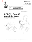
INSTRUCTIONS-REPAIR OWNER’S
MANUAL
824113
This manual contains important
warnings and information.
READ AND RETAIN FOR REFERENCE
Rev A
SUPER NOVA SP
t
ELECTRIC, AIRLESS PAINT SPRAYER
3000 psi (210 bar, 21 MPa) Maximum Working Pressure
Model 824175
Model 820169, Series D
Complete sprayer with hose, gun,
RAC IVr DripLesst Tip Guard and SwitchTipt
Model 824175, Series A
Upright cart; complete sprayer with hose, gun,
RAC IVr DripLesst Tip Guard and SwitchTipt,
tool box
8733
All models are not available in all countries
U.S. PATENT NO. 4,323,741; 4,397,610 P ATENTED
1983, CANADA AND OTHER PATENTS PENDING
Related Manuals
Operator . . . . . . . . . . . . . . . . . . . . . . . . . 824112
..
Displacement Pump . . . . . . . . . . . . . . . . 308190
.
FTx Spray Gun . . . . . . . . . . . . . . . . . . . .308645
.
Spray Tip . . . . . . . . . . . . . . . . . . . . . . . . . 308644
..
Model 820169
Table of Contents
Component Function and Identification . . . . . . . . . . . .2
General Repair Information . . . . . . . . . . . . . . . . . . . . .3.
Grounding . . . . . . . . . . . . . . . . . . . . . . . . . . . . . . . . . . 4
...
Troubleshooting . . . . . . . . . . . . . . . . . . . . . . . . . . . . . .5. .
Motor Test . . . . . . . . . . . . . . . . . . . . . . . . . . . . . . . . . . 9
...
Motor Brush Replacement . . . . . . . . . . . . . . . . . . . .10
.
Displacement Pump Repair . . . . . . . . . . . . . . . . . . . .12
.
Motor Replacement . . . . . . . . . . . . . . . . . . . . . . . . . . 13
..
Motor Start Board . . . . . . . . . . . . . . . . . . . . . . . . . . . 14
..
Power Supply Cord . . . . . . . . . . . . . . . . . . . . . . . . . . 14
..
On/Off Switch . . . . . . . . . . . . . . . . . . . . . . . . . . . . . .14
..
Drive Housing, Connecting Rod, Crankshaft . . . . . . 15
Pressure Control . . . . . . . . . . . . . . . . . . . . . . . . . . . .16
..
Pressure Transducer . . . . . . . . . . . . . . . . . . . . . . . . . 17
..
Suction Hose . . . . . . . . . . . . . . . . . . . . . . . . . . . . . . .17
..
Drain Valve . . . . . . . . . . . . . . . . . . . . . . . . . . . . . . . . .18
..
Model 820169 Sprayer Parts Drawing . . . . . . . . . . . .19
Model 820169 Sprayer Parts List . . . . . . . . . . . . . . . 20
.
Model 824175 Sprayer Parts Drawing . . . . . . . . . . . .21
Model 824175 Sprayer Parts List . . . . . . . . . . . . . . . 22
.
Technical Data . . . . . . . . . . . . . . . . . . . . . . . . . . . . . .23
..
Dimensions . . . . . . . . . . . . . . . . . . . . . . . . . . . . . . . . .23
..
Sherwin-Williams Warranty . . . . . . . . . . . . . . . . . . . .24
.
The SHERWIN-WILLIAMS COMPANY, CLEVELAND, OHIO 44115
ECOPYRIGHT 1998, GRACO INC.
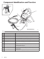
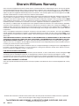
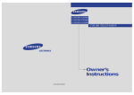
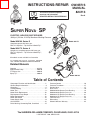
Component Identification and Function
N
C
H
B
A
K
E
G
L
F
M
D
J
Model 820169 Shown
06973
Fig. 1
2
A
Motor
DC motor, 120 Vac, 15A, 1 phase
B
Drive Assembly
Transfers power from DC motor to the displacement pump
C
Pressure Adjusting Knob
Controls fluid outlet pressure
D
ON/OFF Switch
Power switch that controls 120 Vac power to sprayer
E
Fluid Outlet
Hose and spray gun is connected here
F
Displacement Pump
Pressurizes fluid to be sprayed through spray gun
G
50 ft (15 m) Main Hose
1/4 in. ID, grounded, nylon hose with spring guards on both ends
H
RAC IV Tip Guard
Reverse-A-Clean (RAC) tip guard reduces the risk of fluid injection injury
J
Contractor Gun
High pressure spray gun with gun safety latch
K
RAC IV Switch Tip
RAC switch tip atomizes fluid and removes clogs from spray tip without
removing tip from spray gun
L
Pressure Drain Valve
Relieves fluid pressure when open
M
Pressure Control
Controls motor to maintain fluid pressure. Works with pressure
adjusting knob.
N
Spray Gun Safety Latch
Inhibits accidental triggering of spray gun
824113
General Repair Information
WARNING
CAUTION
To reduce risk of pressure control malfunction:
Use needle nose pliers to disconnect a wire. Never
pull on wire, pull on connector.
Mate wire connectors properly. Center flat blade of
insulated male connector in female connector.
Route wires carefully to avoid interference with
other connections of pressure control. Do not
pinch
wires between cover and control box.
EXPLOSION HAZARD
Motor and drive housing are very hot
during operation and could burn skin if
touched. Flammable materials spilled on
hot, bare motor could cause fire or explosion. Have
motor shield in place during operation to reduce
risk of burns, fire or explosion.
CAUTION
Do not run sprayer dry for more than 30 seconds to
avoid damaging pump packings.
Tool List
Phillips screwdriver
Small flat blade
screwdriver
Needle nose pliers
Plastic mallet or 20 oz
(max) hammer
12 in. adjustable wrench
Adjustable, open-end
wrench
Torque wrench
1/4 in. hex key wrench
3/16 in. hex key wrench
5/8 in. socket wrench
3/8 in. open end wrench
1/2 in. open end wrench
3/4 in. open end wrench
7/8 in. open end wrench
High quality motor oil
Bearing grease
1. Keep all screws, nuts, washers, gaskets, and
electrical fittings removed during repair procedures. These parts are not normally provided with
replacement assemblies.
4. Install motor shield before operation of sprayer
and replace if damaged. Motor shield directs
cooling air around motor to prevent overheating. It
can also reduce risk of burns, fire or explosion; see
preceding WARNING.
Pressure Relief Procedure
WARNING
INJECTION HAZARD
System pressure must be manually
relieved to prevent system from starting
or spraying accidentally. Fluid under high
pressure can be injected through skin and cause
serious injury. To reduce risk of injury from injection, splashing fluid, or moving parts, follow Pressure Relief Procedure whenever you:
are instructed to relieve pressure,
stop spraying,
check or service any system equipment,
or install or clean spray tip.
WARNING
ELECTRIC SHOCK HAZARD
To reduce risk of serious injury, including
electric shock, do not touch moving or
electrical parts with fingers or tools while
testing repair. Shut off and unplug sprayer when
inspection is complete. Install all covers, gaskets,
screws and washers before operating sprayer.
2. Test repair after problem is corrected.
3. If sprayer does not operate properly, review
repair procedure to verify procedure was done
correctly. If necessary, see Troubleshooting Guide,
page 5, for other possible solutions.
1.
2.
3.
4.
Lock gun safety latch.
Turn ON/OFF switch to OFF.
Unplug power supply cord.
Unlock gun safety latch. Hold metal part of gun
firmly to grounded metal pail. Trigger gun to relieve
pressure.
5. Lock gun safety latch.
6. Open pressure drain valve. Leave pressure drain
valve open until ready to spray again.
If suspected that spray tip or hose is completely
clogged, or that pressure has not been fully relieved
after following steps above, VERY SLOWLY loosen tip
guard retaining nut or hose end coupling to relieve
pressure gradually, then loosen completely. Now clear
tip or hose obstruction.
824113
3
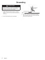
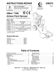
Grounding
WARNING
Improper installation or alteration of grounding plug
results in risk of electric shock, fire or explosion
that could cause serious injury or death.
1. Models 820169 and 824175 require a 120 VAC,
50/60 Hz, 15A circuit with a grounding receptacle.
See Fig. 2.
2. Do not alter ground prong or use adapter.
4
824113
Grounded
Outlets
Grounding Prong
Fig. 2
3. A 12 AWG, 3 wires with grounding prong, 300 ft
(90 m) extension cord may be used. Long lengths
reduce sprayer performance.
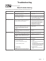
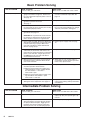
Troubleshooting
Relieve pressure; page 3.
Basic Problem Solving
Check everything in the troubleshooting table before disassembling the sprayer.
TYPE OF PROBLEM
WHAT TO CHECK
If check is OK, go to next check
WHAT TO DO
When check is not OK, refer to this column
Fluid pressure
1. Pressure control knob setting. The pump won’t
develop much pressure if it is at minimum setting (fully counterclockwise).
1. Slowly increase pressure setting to see if
motor starts.
2. For clogged spray tip or fluid filter, if used. See
manual 308645 or 308664.
2. If tip is still clogged, relieve pressure; refer to separate gun or tip instruction manual for tip cleaning. Clean or replace filter
element. See manual 308249.
1. For frozen or hardened paint in pump (20). Using a screwdriver, carefully try to rotate fan at
back of motor by hand. See page 9.
1. Thaw sprayer if water or water-based
paint has frozen in sprayer. Place sprayer in warm area to thaw. Do not start
sprayer until thawed completely. If paint
hardened (dried) in sprayer, replace
pump packings. See page 12
(Displacement Pump Repair).
2. Dixplacement pump connecting rod pin (17).
Pin must be completely pushed into connecting
rod (15), and retaining spring (18) must be
firmly in connecting rod groove. See Fig. 9,
page 12.
2. Push pin into place and secure with
spring retainer.
3. For motor damage. Remove drive housing assembly (11). See page 15. Try to rotate motor
fan by hand.
3. Replace motor (4) if fan won’t turn. See
page 13.
1. Electrical supply. Meter must read:
105–125 VAC for models 820169 and 824175.
1. Reset building circuit breaker; replace
building fuse. Try another outlet.
2. Extension cord for visible damage. Use a volt
meter or test lamp at extension cord outlet to
check.
2. Replace extension cord.
Mechanical
Electrical
3. Sprayer power supply cord (50) for visible dam- 3. Replace power supply cord.
age such as broken insulation or wires.
See page 14.
4. Check motor brushes for the following:
a. Loose terminal screws.
b. Broken or misaligned brush springs.
c. Brushes binding in holders.
d. Broken leads.
e. Worn brushes.
NOTE: The brushes do not wear at same rate
on both sides of motor. Check both brushes.
4. Refer to page 10.
a. Tighten.
b. Replace broken spring and/or align
spring with brush
c. Clean brush holders. Remove carbon
with small cleaning brush. Align brush
leads with slot in brush holder to assure free vertical brush movement.
d. Replace brushes
e. Replace brushes if less than 0.5 in.
long.
824113
5
Basic Problem Solving
TYPE OF PROBLEM
WHAT TO CHECK
If check is OK, go to next check
WHAT TO DO
When check is not OK, refer to this column
Electrical (continued)
5. Motor armature commutator for burn spots,
gouges and extreme roughness. Remove motor cover and brush inspection plates to check.
See page 10.
5. Remove motor and have motor shop
resurface commutator if possible. See
page 13.
6. Motor armature for shorts using armature tester 6. Replace motor. See page 13.
(growler) or perform motor test.
See page 9.
7. Leads from pressure control and motor to motor start board (47) to be sure they are securely
fastened and properly mated.
7. Replace loose terminals; crimp to leads.
Be sure male terminal blades are straight
and firmly connected to mating part.
8. Motor start board (47) by substituting with a
good board. See page 14.
8. Replace board. See page 14.
CAUTION: Do not perform this check until motor armature is determined to be good. A bad
motor armature can burn out a good board.
9. Power supply cord (50). Disconnect black and
white power cord terminals; connect volt meter
to these leads. Plug in sprayer. Meter must
read: 105–125 VAC for models 820169 and
824175. Unplug sprayer.
9. Replace power supply cord. See page
14.
10. ON/OFF switch (52). Disconnect the motor
start board (47) and switch and connect volt
meter between exposed terminal on switch and
power cord’s white wire. Plug in sprayer and
turn ON.Meter must read: 105–125 VAC for
models 820169 and 824175.
10. Replace ON/OFF switch. See page 14.
11. Motor thermal cutout switch. Connect ohmmeter between motor’s red leads. Meter should
read 1 ohm maximum.
11. Allow motor to cool. Correct cause of
overheating. If switch remains open after
motor cools, replace motor.
12. Remove pressure control (64) and check microswitch operation with ohmmeter:
(1) With pressure knob at lowest setting and
stem pushed into control, readings should
be: white & black = 1 ohm max.
white & red = open.
(2) With pressure knob at highest setting,readings should be: white & black = open;
white & red = 1 ohm max.
12. Replace pressure control. See page 16.
13. Pressure transducer (29) for hardened paint or
damaged or worn components. See page 17.
13. Replace transducer. See page 17. Thorough system flushing will help extend life
of transducer.
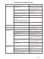
Intermediate Problem Solving
TYPE OF PROBLEM
WHAT TO CHECK
If check is OK, go to next check
WHAT TO DO
When check is not OK refer to this column
Low output
1. For worn spray tip.
1. Follow Pressure Relief Procedure then
replace tip. See your separate gun or tip
manual.
2. Be sure pump does not continue to stroke
when gun trigger is released. Plug in and turn
on sprayer. Prime with paint. Trigger gun momentarily, then release and lock safety latch.
Relieve pressure, turn off and unplug sprayer.
2. Service pump. See page 12.
6
824113
Intermediate Problem Solving
TYPE OF PROBLEM
WHAT TO CHECK
If check is OK, go to next check
WHAT TO DO
When check is not OK, refer to this column
Low output (continued)
3. Release gun trigger. Observe resting position of 3. If pump consistently comes to rest with
pump rod (107).
rod (107) fully extended, the piston packings and/or piston valve may be worn.
Service the pump. See page 12.
4. Electrical supply. Meter must read: 105–125
VAC for models 820169 and 824175.
4. Reset building circuit breaker; replace
building fuse. Repair electrical outlet or
try another outlet.
5. Extension cord size and length; must be at
least 12 gauge wire and less than 150 ft
(45 m) long.
5. Replace with a correct, grounded extension cord.
6. Motor brushes. See Electrical – What To
Check, item 4, on page 5.
6. See page 10.
7. Motor start board (47) by substituting with a
good board.
7. Replace board. See page 14.
CAUTION: Do not perform this check until motor armature is determined to be good. A bad
motor armature can burn out a good board.
8. Motor armature for shorts by using an armature 8. Replace motor. See page 13.
tester (growler) or perform motor test. See page
9.
Drain valve leaks
1. Drain valve for correct torque and/or worn
parts. Check for debris trapped on seat.
9. Tighten to 185 in–lb (21 N.m). Clean
valve and replace with new gasket (42a)
and sealant (42d). See page 18.
Transducer leaks
1. Slight leakage from transducer is normal.
1. Periodically remove residue from its cylinder port. See page 17.
No output: motor runs and
pump strokes
1. Paint supply.
1. Refill and reprime pump.
2. For clogged intake strainer.
2. Remove and clean, then reinstall.
3. For loose suction tube or fittings. See
page 17.
3. Tighten; use thread sealant on npt
threads of adapter (38).
4. To see if intake valve ball and piston ball are
seating properly. See page 12.
4. Remove intake valve and clean. Check
ball and seat for nicks; replace as needed. See page 12. Strain paint before using to remove particles that could clog
pump.
5. For leaking around throat packing nut which
may indicate worn or damaged packings. See
page 12.
5. Replace packings. See page 12. Also
check piston valve seat for hardened
paint or nicks and replace if necessary.
Tighten packing nut/wet-cup.
6. Release gun trigger. Observe resting position of 6. If pump consistently comes to rest with
pump rod (107).
rod (107) fully extended, the piston packings and/or piston valve may be worn.
Service the pump. See page 12.
No output: motor runs but
pump does not stroke
1. Displacement pump connecting rod pin (17).
See Fig. 9, page 12.
1. Replace pin if missing. Be sure retainer
spring (18) is fully in groove all around
connecting rod.
7. Connecting rod assembly (15) for damage.
See page 15.
7. Replace connecting rod assembly. See
page 15.
8. Be sure crank in drive housing rotates; plug in
sprayer and turn on briefly to check. Turn off
and unplug sprayer. See page 15.
8. Check drive housing assembly for
damage and replace if necessary. See
page 15.
824113
7
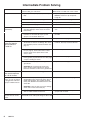
Intermediate Problem Solving
TYPE OF PROBLEM
WHAT TO CHECK
If check is OK, go to next check
WHAT TO DO
When check is not OK, refer to this column
Spray Pattern Variations
1. Spray tip worn beyond sprayer pressure capability.
1. Replace spray tip.
NOTE: A smaller size tip will provide
longer life.
2. Transducer (29) for wear or damage.
2. Replace transducer. See page 17.
3. Pressure control (64) for smooth operation.
3. Replace pressure control. See page 16.
4. Low output section, page 7.
Motor Is Hot and Runs
Intermittently
Building Circuit Breaker
Opens As Soon As
Sprayer Switch Is
Turned On.
1. Determine if sprayer was operated at high pres- 1. Decrease pressure setting or increase tip
sure with small tips, which causes excessive
size.
heat build up.
2. Be sure ambient temperature where sprayer is
located is no more than 90 F (32 C) and
sprayer is not located in direct sun.
2. Move sprayer to shaded, cooler area if
possible.
3. Motor.
3. Replace motor. See page 13.
1. All electrical wiring for damaged insulation, and
all terminals for loose fit or damage. Also check
wires between pressure control and motor. See
page 13.
1. Repair or replace any damaged wiring or
terminals. Securely reconnect all wires.
2. For missing motor brush inspection plate gasket (see page 9), bent terminal forks or other
metal to metal contact points which could
cause a short.
2. Correct faulty conditions.
3. Motor armature for shorts. Use an armature
3. Replace motor. See page 13.
tester (growler) or perform motor test. See page
9. Inspect windings for burns.
4. Motor start board (47) by substituting with a
good board.
4. Replace board. See page 14.
CAUTION: Do not perform this check until
motor armature is determined to be good. A
bad motor armature can burn out a good board.
Circuit breaker opens
after sprayer operates
for 5 to 10 minutes.
1. Basic Problems – Electrical on page 5.
Building circuit breaker
opens as soon as sprayer
is plugged into outlet and
sprayer is NOT turned on.
1. ON/OFF switch (52). Be sure sprayer is unplugged! Disconnect wires from switch. Check
switch with ohmmeter. The reading should be
infinity with ON/OFF switch OFF, and zero with
switch ON.
1. Replace ON/OFF switch. See page 14.
CAUTION: A short in motor circuit can damage
switch and or motor start board (47).
2. Electrical supply. Meter must read: 105–125
VAC for models 820169 and 824175.
Unit will not run on generator but does run on AC
power
8
824113
2. If voltage is too high, do not operate
sprayer until corrected.
Generator peak voltage. Models 820169 and
Use AC power or a different generator
824175.will not run if the peak voltage is above 190V
.
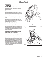
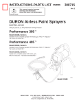
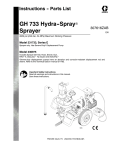
Motor Test
Relieve pressure; page 3.
For checking armature, motor winding and brush
electrical continuity.
Setup
Remove the drive housing. See page 15. This is to
ensure that any resistance you notice in the armature
test is due to the motor and not to worn gears in the
drive housing.
B
A
Remove the motor brush inspection covers (A). See
Fig. 3.
Remove the junction box screws (56). Lower the
junction box. Disconnect the two leads (C) from the
motor to the board (47). See Fig. 4.
Armature Short Circuit Test
Remove the fan cover (B). See Fig. 3.
Spin the motor fan by hand. If there are no shorts, the
motor will coast two or three revolutions before coming
to a complete stop. If the motor does not spin freely,
the armature is shorted and the motor must be replaced. See page 13.
Model 820169 Shown
Fig. 3
06975
MOTOR
Armature, Brushes, and Motor Wiring
Open Circuit Test (Continuity)
Connect the two black motor leads together with a test
lead. Turn the motor fan by hand at about two revolutions per second.
When turning the fan on a DC motor, normally you
sense an even, pulsing resistance. If there is irregular
turning resistance, or no turning resistance, check and
repair the following as needed: broken brush springs,
brush leads, motor leads; loose brush terminal screws
or motor lead terminals; worn brushes. See page 10.
If there is still uneven or no turning resistance, replace
the motor. See page 13.
BLACK/
WHITE
BLACK
59
C
RED
56
47
Fig. 4
04720
824113
9
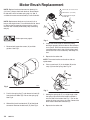
Motor Brush Replacement
NOTE: Replace brushes when worn to about 0.5 in.
(12.5 mm). Always check both brushes. Brush Repair
Kit 236–967, which includes spring clip 112–766, is
available for motors manufactured by Pacific Scientific.
Motor lead; do not disconnect
Minimum 0.5” (12.5 mm)
Included in Brush Repair
Kit 236–967
NOTE: Replacement brushes may last only half as
long as the original ones. To maximize brush life, break
in new brushes by operating the sprayer for at least
one hour with no load (remove the pump connecting
rod pin).
H
G
C
F
B
E
Relieve pressure; page 3.
D
Fig. 6
4. Inspect the commutator for excessive pitting,
burning or gouging. A black color on the commutator is normal. Have the commutator resurfaced by
a qualified motor repair shop if the brushes seem
to wear too fast or arc excessively. See Step 9.d.,
also.
1. Remove both inspection covers (A) and their
gaskets. See Fig 5.
5. Repeat for the other side.
NOTE: The motor brushes on the other side are
upside down.
6. Place a new brush (C) in the holder (B) so the
ramp (H) faces the spring. See Fig. 16.
A
F
G
C
02831A
Fig. 5
Fig. 7
2. Push in the spring clip (F) and release its hook (G)
from the brush holder (B). Pull out the spring clip.
See Fig 6.
3. Slide off the brush lead terminal (E) off the blade
connector. Remove the old brush (C). See Fig 6.
10
824113
E
7. Holding the spring clip (F) at a slight angle, slide
the spring clip into the brush holder and hook it
over the end of the holder. See Fig. 7. Pull on the
spring clip to be sure it stays in place. Connect the
brush lead to the blade connector (E).
8. Repeat for the other side.
Motor Brush Replacement
9. Test the brushes.
a. Remove the pump connecting rod pin (17).
See Fig. 9, page 12.
b. With the sprayer OFF, turn the pressure control knob fully counterclockwise to minimum
pressure. Plug in the sprayer.
c.
Turn the sprayer ON. Slowly increase the
pressure until the motor is at full speed.
d. Inspect the brush and commutator contact area
for excessive arcing. Arcs should not trail or
circle around the commutator surface.
WARNING
MOVING PARTS HAZARD
Do not touch the brushes, leads, springs
or brush holders while the sprayer is
plugged in to reduce the risk of electric
shock and serious injury.
10. Install the brush inspection covers and gaskets.
11. Break in the brushes. Operate the sprayer for at
least one hour with no load. Install the pump
connecting rod pin. See Fig. 9, page 12.
824113
11
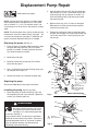
Displacement Pump Repair
Relieve pressure; page 3.
NOTE: Packing Repair Kit 235703 is available. Reference numbers of parts included in the kit are marked
with an asterisk, i.e., (121*). For the best results, use
all the new parts in the kit, even if the old ones still look
good.
NOTE: To minimize down time, and for the best sprayer
performance, check the motor brushes (see page 10)
and clean the transducer (see page 17) whenever you
repack the pump. Replace these parts as needed.
2. Align the hole in the rod (107) with the connecting
rod assembly (15). Use a screwdriver to push the
retaining spring (18) up and push in the pin (17).
Push the retaining spring (18) into place around
the connecting rod.
3. Replace the o-ring (27) if it is worn or damaged.
Reconnect the suction and drain hoses (32,33).
Install the front cover (13).
4. Tighten the packing nut (102) just enough to stop
leakage, but no tighter. Fill the packing nut/wet-cup
1/3 full with Graco TSL. Push the plug (123) into
the wet-cup.
Removing the pump (See Fig. 8.)
1. Flush the pump, if possible. Relieve pressure. Stop
the pump with the piston rod (107) in its lowest
position, if possible. To lower the piston rod manually, rotate the motor fan blades.
2. Remove the filter (85).
13
17
85
18
3. Remove suction hose or tube (32).(For suction
hose, refer to page 17.
107
120
*122
20
4. Use a screwdriver to push the retaining spring (18)
up and push out the pin (17).
21
*121
36
5. Loosen the screws (21). Remove the pump (20).
*119
118
Repairing the pump
33
32
See manual 308190 for pump repair instructions.
27
Torque to
50 ft–lb (68 N.m)
38
Apply anaerobic
polycrystal pipe
sealant
Installing the pump (See Fig. 8 and 9.)
1. Mount the pump on the drive housing. Tap it into
the alignment pins with a soft hammer. Tighten the
screws (21) to 50 ft-lb (68 N.m).
Fig. 8
Model 820169 Shown
02832B
17
15
WARNING
123
MOVING PARTS HAZARD
Be sure the retaining spring (18) is firmly
in the groove all the way around, to prevent the pin (17) from working loose due
to vibration. See Fig. 9.
If the pin works loose, it or other parts could break
off due to the force of the pump action. These parts
could be projected into the air and result in serious
injury or property damage, including the pump
connecting rod or drive housing.
12
824113
18
Torque to
50 ft–lb (68 N.m)
21
Fig. 9
102
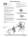
Motor Replacement
10. Assemble the drive housing to the motor. Follow
steps 8 to 10 on page 15.
Relieve pressure; page 3.
11. Connect the wires in the junction box. Refer to Fig.
13 on page 14. Install the junction box.
NOTE: See Fig. 12 except where noted.
1. Relieve pressure.
2. Try to stop the pump with the piston rod (107) in its
lowest position. To lower the piston rod manually,
rotate the motor fan blades. Use a screwdriver to
push the retaining spring (18) up and push out the
pin (17). See Fig. 10.
12. Connect the piston rod (107) to the drive housing;
see page 12, Installing the Pump , Step 2 and the
WARNING following it.
17
15
3. Remove the screws (56) and lower the junction
box (59). Disconnect the motor wires and the
pressure control wire (A) from the motor start
board. Refer to Fig. 13 on page 14.
18
Fig. 10
4. Remove the front cover (13).
01068
5. Turn the displacement pump rod (107) so the pin
hole aligns with the bottom drive housing screw
(19). See Fig. 11. Remove the three drive housing
screws and lockwashers (19,6). Also see Fig. 12.
107
6. Remove the two motor screws (5) and the lock
washers (6).
7. Tap the lower rear of the drive housing (11) with a
plastic mallet to loosen the motor. Pull the drive
housing straight off the motor while guiding the
harness (A) from the motor. Do not allow the gear
(16) to fall. Read the CAUTION on page 15.
19,6
01074
Fig. 11
8. Remove the two screws (46) and lift the motor off
the base (66).
C
B
9. Align the new motor with the base and reinstall the
screws (46).
6
5
4
A
12
16
11
Torque to 2.4 N.m (21 in–lb)
Quantity of three
Quantity of one
6
19
59
13
Fig. 12
46
56
31
34
05119
824113
13
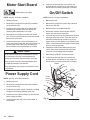
Motor Start Board
6. Install the junction box. Be sure no leads are
pinched against the motor or by the motor start
board. Also be sure the gasket (89) is installed.
On/Off Switch
Relieve pressure; page 3.
NOTE: See Fig. 13 for this procedure.
NOTE: See Fig. 13 for this procedure.
1. Relieve pressure.
1. Relieve pressure.
2. Remove the junction box screws (56) and lower
the junction box (59).
2. Remove the junction box screws (56) and lower
the junction box (59).
3. Disconnect the motor wires (B) and the 3-wire
connector (A) from the motor start board (47).
Observe where connections are made.
3. Remove the nut and rubber boot (55).
4. Remove the screws (58) and motor start board
(47). Transfer the white thermal paste from the old
board to the new board.
5. Install the new motor start board. Reconnect all
wires. Install the junction box. Be sure no leads are
pinched against the motor or by the motor start
board. Also be sure the gasket (89) is installed.
CAUTION
Be sure the flat blade of the insulated male connector is centered in the wrap–around blade of the
female connector when the connections are made.
Route all wires carefully to avoid interference with
the motor start board or junction box.
4. Disconnect the black wires from the ON/OFF
switch (52) and remove the switch.
5. Place the ring terminal of the ground wire (53) over
the barrel of the new switch. Install the switch so
the internal tab of the anti-rotation ring (54) engages with the vertical groove in the threads of the
switch, and the external tab engages with the blind
hole (C) of the junction box.
6. Powder the inside of the rubber boot (55) with
talcum, then shake the excess out of the boot.
Install the nut and rubber boot and tighten.
7. Reconnect the ON/OFF switch black wires.
8. Install the junction box. Be sure no leads are
pinched against the motor or by the motor start
board. Also be sure the gasket (89) is installed.
MOTOR
These precautions are essential to reduce the risk of
a malfunction.
GREEN
49
Power Supply Cord
BLACK/
WHITE
NOTE: See Fig. 13 for this procedure.
59
3. Disconnect the power supply cord leads, including
the green wire to the grounding screw (49).
58
824113
55
RED
A
4. Loosen the strain relief bushing (51). Remove the
power supply cord (50).
14
54
B
2. Remove the junction box screws (56) and lower
the junction box (59).
89
52
BLACK
1. Relieve pressure.
5. Install the new cord (50) in the reverse order of
disassembly.
GREEN/
53 YELLOW
50
51
C
56
47
Fig. 13
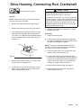
Drive Housing, Connecting Rod, Crankshaft
CAUTION
Relieve pressure; page 3.
Do not allow the gear (16) to fall; it may stay attached to the drive housing or to the motor.
Removal
NOTE: Inspect parts as they are removed. Replace
parts that are worn or damaged.
1. Remove the displacement pump. See page 12.
2. Remove the pressure control (64). See page 16.
3. Turn the displacement pump rod (107) so the pin
hole aligns with the bottom drive housing screw
(19). See Fig. 14. Remove the three drive housing
screws and lockwashers (19,6). Also see Fig. 15
on page 16.
107
6. Remove and inspect the crankshaft (12) and the
connecting rod (15).
Installation
7. Install the connecting rod.
8. Lubricate the inside of the drive housing bearing
with SAE non-detergent oil. Pack the roller bearing
and gears with the grease supplied.
NOTE: The gears and bearings between the drive
housing (11) and motor front end bell (C) should contain a total of 3 fl. oz. (29 cc) of grease.
19,6
Fig. 14
Do not lose the thrust balls (11a or 4a) or let them fall
between the gears, which will damage the drive housing if not removed. The balls, which are heavily covered
with grease, usually stay in the gear recesses, but
could be dislodged. If the balls are not in place, the
bearings will wear prematurely.
9. Place the large washer (12a) and then the small
washer (12b) on the crankshaft (12).
01074
4. Remove the two motor screws (5) and lock washers (6). See Fig. 15 on page 16.
5. Tap the lower rear of the drive housing (11) with a
plastic mallet to loosen the motor. Pull the drive
housing straight off the motor.
10. Lift the crank to the top of the stroke and insert
crankshaft (12). Align the gears and push the drive
housing (11) straight onto the motor and the locating pins. Install the screws (19, 5) and their lockwashers (6). Torque to 80 in–lb (9 N.m).
11. Install the displacement pump. See page 12.
12. Install the pressure control (64). See page 16.
Install the front cover (13).
824113
15
Drive Housing, Connecting Rod, Crankshaft
5,6
64
REF A
12a
11a
12
C
4a
12b
16
Torque to 2.4 N.m (21 in–lb)
Quantity of three
Quantity of one
Apply a total of 3 fl. oz.(29 cc)
of grease to gears.
A
47
59
56
31
6
Note: Filter
not shown
13
34
Fig. 15
15
11
19
02815
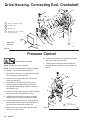
Pressure Control
Relieve pressure; page 3.
NOTE: See Fig. 16 for this procedure.
NOTE: The pressure control (64) cannot be repaired
or adjusted. If it has malfunctioned, replace it.
8. Install the front cover (13). Connect the harness
(A) to the motor start board (47).
9. Install the junction box. Be sure no leads are
pinched against the motor or by the motor start
board.
1. Remove the front cover (13). Remove the screws
(56). Lower the junction box (59).
64
63
2. Disconnect the harness connector (A) from the
motor start board (47).
11
3. Remove the screws (63). Pull forward on the
pressure adjusting knob and tip the pressure
control (64) forward and up to detach it from the
drive housing (11).
4. Guide the harness (A) through the motor and drive
housing and remove the pressure control.
13
A
5. Guide the harness of the new pressure control
through the drive housing and motor passages.
6. Install the new pressure control. Tip the pressure
control down and back into the drive housing (11).
Do not pinch or damage the harness (A).
7. Loosely install the screws (63) and then torque
them to 21 in–lb (2.4 N.m).
16
824113
59
56
Fig. 16
Torque to
21 in–lb (2.4 N.m)
02816A
Pressure Transducer
Relieve pressure; page 3.
NOTE: See Fig. 17 for this procedure.
1. Remove the displacement pump. See page 12.
2. Use a pull–twist motion to remove the transducer
(29) from the pump manifold (101).
3. Clean paint residue from the hole in the manifold;
do not scratch the surface of the hole.
29
4. Lightly apply oil to the o-ring of the new transducer.
101
5. Install the transducer in the pump manifold, while
guiding the o-ring and backup ring into place.
6. Align the holes in the transducer as shown by the
arrows in Fig. 17.
7. Install the displacement pump. See page 12.
Fig. 17
02817A
Suction Hose
Model 820169
Lubricate
Relieve pressure; page 3.
Note: Filter
not shown
13
1. Remove the drain hose (33) from the clip. Remove
the front cover (13).
2. Pull upward on the hose (32) while unscrewing it
from the inlet tube (38). The hose coupling (A)
threads will engage and the hose will separate
from the tube.
33
3. Replace the o–ring (27) if it is worn or damaged.
36
4. Lubricate the o–ring (27) and the inlet tube (38)
threads with light grease.
32
27
5. Align the suction hose coupling with the threads of
the inlet tube (38). Tighten the hose onto the tube at
least 4 turns to ensure that the threads have disengaged and can function as a swivel joint.
CAUTION
A
38
Fig. 18
Model 820169 Shown
06978
Misalignment or cross-threading will damage the
parts and/or create shavings which can cause the
o–ring (27) to leak.
824113
17
Drain Valve
Repair
Relieve pressure; page 3.
42a
Apply thread sealant
42b
Apply grease
to face of base
42d
42c
1. Unscrew the spring retainer from the valve body.
Remove the spring, washers and stem/ball. Clean
any debris from the ball or seat area.
Torque into pump
manifold to 185 in–lb
(21 N.m)
Handle shown
in closed position
42
44
45
NOTE: Whenever the gasket (42a) is removed, replace it with a new one.
3. Coat the o-ring (42d) with grease. Press the stem
into the valve body. Install the spring, washers and
spring retainer into the valve body.
4. Place the seat (42b) in the valve body so the
lapped side is toward the ball. Apply a small
amount of grease to the new gasket (42a) and
install it in the valve body.
43
Fig. 19
2. If replacing the gasket (42a) or seat (42b), pry out
the gasket.
02819
NOTE: The gasket will protrude from the end of the
valve until the valve is tightened into pump, which
correctly seats the gasket.
Replacement
1. Turn the handle (45) to the closed position. Drive
out the pin (44). Remove the handle.
2. Remove the base (43).
3. Unscrew the drain valve (42). The gasket (42a)
and seat (42b) will stay in the valve.
18
824113
1. Apply a small amount of thread sealant (42e) onto
the valve (42) threads. Tighten the valve into the
pump manifold to 185 in–lb (21 N.m).
2. Lightly grease the face of the base (43) and install
the base. Turn the stem so the pin hole is vertical.
3. Securely install the handle (45) and drive pin (44).
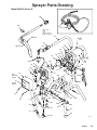
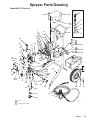
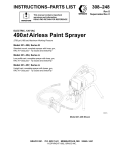
Sprayer Parts Drawing
Model 820169, Series D
39
30
74
67
Label
See detail
on page 20
24
REF 33
4e
3
REF 32
6
64
5
4
4a
16
12
63
19
15
6
11b
4f
4g
12a
89
11a
17
OUTSIDE 35
LABEL
12b
11
13
18
26
66
50
14
56
INSIDE
LABEL
29
42a
42b
42d
42c
28
31
34
21
20
36
32
33
23
23
42
43
44
46
45
37
27
38
25
06974
824113
19
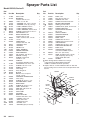
Sprayer Parts List
Model 820169, Series D
Ref.
No.
Part No.
Description
3
4{
111700
237458
4a
4b
4c
4dY
4eY
4fY
5
6
11
100069
111616
107503
187784
187791
187975
100643
105510
224965
11a
11b
12
100069
111726
224803
12a
12b
13
14Y
15
16
17
18
19
180131
107434
187789
177762
218359
218364
176818
176817
103345
20
235699
21
23
24
25
26
27H
28
111706
111715
192166
112759
239276
104938
162453
GRIP, handle
MOTOR KIT
Includes items 4a to 4f
. BALL, sst, 1/4” dia.
. TERMINAL, flat, 1/4” (f), 18 awg
. TERMINAL, 3/16” (m), 16 awg
. LABEL, DANGER, French
. LABEL, DANGER, English
. LABEL, WARNING, electric shock
SCREW, socket head, 1/4–20 x 1”
LOCKWASHER, 1/4”
DRIVE HOUSING KIT
Includes item 11a, 11b
. BALL, stainless steel, 1/4” dia.
. PLUG
CRANKSHAFT
Includes items 12a, 12b
. BEARING, thrust
. BEARING
COVER, front
LABEL, WARNING
CONNECTING ROD
GEAR REDUCER
PIN, headless, 3/8” dia. x 1”
SPRING, retaining
SCREW, socket head,
1/4–20 x 1–1/4”
PUMP KIT
See manual 308190 for parts
CAPSCREW, 7/16–14 x 1–3/4”
SCREW, 5/16–18 x 1–1/4”
HANDLE, sprayer
CAP, tubing
LEG, with gusset
O–RING
NIPPLE, hex, 1/4 npsm x
1/4 npt, 1–3/16”
PRESSURE TRANSDUCER
CLIP, spring
SCREW, filh, 8–32 x 1–1/4”
SUCTION HOSE & TUBE
DRAIN HOSE
SCREW, filh, 8–32 x 2–1/2”
LABEL, identification
ADAPTER, tube, 9/16–18
LEG, sprayer
INLET TUBE
STRAINER
DRAIN VALVE KIT
Includes items 42a to 42e
. GASKET, valve seat
. SEAT, drain valve
. STEM, drain valve
. O–RING, stem
. SEALANT, pipe (not shown)
29
30
31
32
33
34
35
36
37
38
39
42
235009
114026
108850
187624
187652
111705
824172
111612
187895
192167
235004
235014
42a
42b
42c
42dH
42e
111699
187615
224968
168110
110110
20
824113
Qty.
1
1
1
2
2
1
1
1
2
5
1
1
1
1
1
1
1
1
1
1
1
1
5
1
2
6
1
4
1
1
1
1
1
1
1
1
3
1
1
2
1
1
1
1
1
1
1
1
Ref.
No.
Part No.
43
44
45
46
47
48Y
49
50
51
224807
111600
187625
110997
235707
186620
110037
235010
111617
Description
Qty.
BASE, valve
1
PIN, grooved, 3/32 x 1”
1
HANDLE, drain valve
1
SCREW, washer/hex hd, 5/16”
2
MOTOR START BOARD
1
LABEL, ground terminal
1
SCREW, mach, pnhd, 10–24 x 5/8”
1
POWER CORD SET
1
STRAIN RELIEF BUSHING,
1
3/8–18 npt
52
105679
SWITCH, ON/OFF
1
53
235035
GROUND HARNESS
1
54
105658
LOCKING RING
1
55
105659
BOOT, switch
1
56
111703
SCREW, filh, 10–24 x 3”
4
58
100035
SCREW, pan hd, 8–32 x 5/16”
2
59
187795
JUNCTION BOX
1
63
111704
SCREW, filh, 10–24 x 1–5/8”
2
64
239515
PRESSURE CONTROL KIT
1
66
189932
BASE, motor
1
67
238350
CONTRACTOR FTx GUN
1
See manual 308645 for parts
68
206994
TSL, 8 oz. (not shown)
1
74
238361
HOSE, grounded, nylon; 1/4” ID;
1
cpld 1/4 npsm(f); 50 ft (15 m);’
spring guards both ends
89
187963
GASKET
1
Y Extra warning labels available free of charge.
{ Motor Brush and Spring Replacement Kit,
236967 is available. Purchase separately.
H Replace Ref. No. 27 with 114048 and Ref. No. 42d with
112319 if using severe solvents such as lacquer thinner and
acetone.
MOTOR
GREEN
48
49
GREEN/
53 YELLOW
50
51
4c
BLACK/
WHITE
89
52
BLACK
54
4b
55
59
RED
58
4c
47
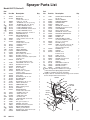
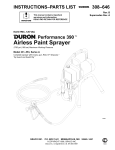
Sprayer Parts Drawing
Model 824175, Series A
3
93
90
72
91
78
24
4
19
4a
12a
4d
4e
on opposite side
12
11b
4f
on opposite side
4g
on opposite side
19
15
35
17
OUTSIDE
LABLE
18
23
105
16
63
96
100
12b
64
62
11a
89
46
59
56
11
29
20 50
38 28
42a
42b
42d
42c
31
34
14
INSIDE
LABLE
98
99
66
42
21
13
41
40
43
36
32
44
45
26
33
25
30
74
37
65
67
39
Label
See page 22 for detail
824113
21
Sprayer Parts List
Model 824175, Series D
Ref.
No.
Part No.
Description
3
4{
192027
237458
4a
4b
4c
4dY
4eY
4fY
4gY
5
6
11
100069
111616
107503
194177
187791
194176
192838
100643
105510
224965
11a
11b
12
100069
111726
224803
12a
12b
13
14Y
15
16
17
18
19
180131
107434
187789
177762
218359
218364
176818
176817
114803
20
235699
21
23
24
25
26
28
111706
112620
239998
105521
113088
162453
29
30
31
32
33
34
35
36
37
39
42
235009
192648
108850
192169
061032
111705
824172
205437
101242
183770
235014
42a
42b
42c
42dH
42e
43
44
45
46
47
48Y
49
50
111699
187615
224968
168110
110110
224807
111600
187625
110997
235707
186620
110037
235010
SLEEVE, cart
MOTOR KIT
Includes items 4a to 4f
. BALL, sst, 1/4” dia.
. TERMINAL, flat, 1/4” (f), 18 awg
. TERMINAL, 3/16” (m), 16 awg
. LABEL, DANGER, French
. LABEL, DANGER, English
. LABEL, WARNING, electric shock
. LABEL, WARNING, French
SCREW, socket head, 1/4–20 x 1”
LOCKWASHER, 1/4”
DRIVE HOUSING KIT
Includes item 11a, 11b
. BALL, stainless steel, 1/4” dia.
. PLUG
CRANKSHAFT
Includes items 12a, 12b
. BEARING, thrust
. BEARING
COVER, front
LABEL, WARNING
CONNECTING ROD
GEAR REDUCER
PIN, headless, 3/8” dia. x 1”
SPRING, retaining
SCREW, socket head, w/nylon patch
1/4–20 x 1–1/4”
PUMP KIT
See manual 308190 for parts
CAPSCREW, 7/16–14 x 1–3/4”
SCREW, 6–32 x 0.187”
HANDLE, sprayer
PLUG, tubing
WHEEL, sprayer
NIPPLE, hex, 1/4 npsm x
1/4 npt, 1–3/16”
PRESSURETRANSDUCER
CLIP, spring
SCREW, filh, 8–32 x 1–1/4”
SUCTION TUBE
DRAIN TUBE
SCREW, filh, 8–32 x 2–1/2”
LABEL, identification
CONNECTOR, tube
RING, retaining, wheel
STRAINER
DRAIN VALVE KIT
Includes items 42a to 42e
. GASKET, valve seat
. SEAT, drain valve
. STEM, drain valve
. O–RING, stem
. SEALANT, pipe (not shown)
BASE, valve
PIN, grooved, 3/32 x 1”
HANDLE, drain valve
SCREW, washer/hex hd, 5/16”
MOTOR START BOARD
LABEL, ground terminal
SCREW, mach, pnhd, 10–24 x 5/8”
POWER CORD SET
22
824113
Ref.
No.
Part No.
Description
2
51
111617
1
1
2
2
1
1
1
1
3
3
1
52
53
54
55
56
58
59
62
63
64
65
66
67
105679
235035
105658
105659
111703
100035
187795
103117
111704
241092
176884
240007
238350
68
72
74
206994
178565
238361
78
89
90
183350
187963
824109
91
92
93
96
97
98
99
100
105
824176
194105
108865
114271
194187
824110
114423
194500
108865
STRAIN RELIEF BUSHING,
3/8–18 npt
SWITCH, ON/OFF
GROUND HARNESS
LOCKING RING
BOOT, switch
SCREW, filh, 10–24 x 3”
SCREW, pan hd, 8–32 x 5/16”
JUNCTION BOX
RING, retaining, handle
SCREW, filh, 10–24 x 1–5/8”
PRESSURE CONTROL KIT
WASHER, axle
FRAME, cart
CONTRACTOR FTx GUN
See manual 308645 for parts
TSL, 8 oz. (not shown)
BUTTON, spring
HOSE, grounded, nylon; 1/4” ID;
cpld 1/4 npsm(f); 50 ft (15 m);’
spring guards both ends
WASHER, flat
GASKET
SHIELD, motor
includes 91, 93
LABEL, shroud
BRACKET, shield
SCREW, cap, pan head
STRAP, retaining
SPACER
TOOL BOX, includes 99
SCREW, self-tapping
BRACKET, shield
SCREW, cap, button hd
Qty.
1
1
1
1
1
1
1
1
1
1
1
5
1
2
4
1
2
2
1
1
1
1
1
1
3
1
1
2
1
1
1
1
1
1
1
1
1
1
2
1
1
1
1
Qty.
1
1
1
1
1
4
2
1
2
2
1
4
1
1
1
2
1
2
1
1
2
1
4
1
2
1
3
1
2
Y Extra warning labels available free of charge.
{ Motor Brush and Spring Replacement Kit,
236967 is available. Purchase separately.
H Replace Ref. No. 42d with 112319 if using severe solvents
such as lacquer thinner and acetone.
MOTOR
GREEN
48
49
GREEN/
53 YELLOW
50
89
51
4c
BLACK/
WHITE
52
BLACK
54
4b
55
59
RED
58
4c
47
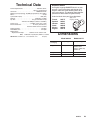
Technical Data
Power Requirements . . . . . . . . . . . . . . . . . . .120
. VAC, 60 Hz,
1 phase, 15A minimum
Generator . . . . . . . . . . . . . . . . . . . . . . . . . . .3000W
.
minimum
Working Pressure Range 0–3000 psi (0–210 bar, 0–21 MPa)
Motor . . . . . . . . . . . . . . . . . . . . . . . . . . . . . . . . . . . . . . .3/4
. . .hp
Cycles/Gallon (liter) . . . . . . . . . . . . . . . . . . . . . . . . . 620
. . (164)
Delivery . . . . . . . . . . . . . . . . . . . . . . . . . . . 0.50
. . gpm (1.9 lpm)
Tip Size . . . . . . . . . . . . . . . . . . . . . . one
. . gun to 0.023 new tip
with latex at 2000 psi (138 bar, 13.8 MPa)
Power Cord . . . . . . . . . . . . . . . . . 14
. AWG, 3 wire, 6 ft (1.8 m)
Inlet Paint Strainer . . . . . . . . . . . . . . . 12
. mesh (1525 micron)
Stainless Steel Screen, reusable
Pump Inlet Size . . . . . . . . . . . . . . . . . . . . . . . . . . . . .1/2
. npt(f)
Fluid Outlet Size . . . . . . . . . . . . . . . . . . . . . . . . . . . . 1/4
. . npsm
Wetted Parts:
Displacement Pump . . . . . . . Stainless steel, Carbon steel,
P
TFE, Aluminum, Polyethylene, Delrin , Leather
NOTE:PTFE and Delri is an are trademarks of the
DANGER LABELS
An English language DANGER label is on your
sprayer. If you have painters who do not read
English, order one of the following labels to apply to your sprayer. The drawing shows the best
placement of these labels for good visibility.
Order the labels from your Graco distributor.
French
Spanish
German
Greek
Korean
English
194177
185961
186041
186045
186049
194176
Apply other
language here
Dimensions
Company.
Model 820169
Model 824175
Weight (dry w/o
packaging)
37 lb (17 kg)
61 lb (27.7 kg)
Height
19 in. (483 mm)
29.5 in. (749 mm)
Handle down
39.5 in. (1003 mm)
Handle up
Length
15 in. (381 mm)
21 in. (533 mm)
Width
14 in. (356 mm)
20.5 in. (521 mm)
824113
23
Sherwin-Williams Warranty
Graco warrants all equipment listed in this manual which is manufactured by Graco and bearing its name to be free from defectsin
material and workmanship on the date of sale by an authorized Graco distributor to the original purchaser for use. With the
ception
ex
of
any special extended or limited warranty published by Graco, Graco will, for a period of twelve months
from the date of sale, repair or
replace any part of the equipment determined by Graco to be defective. This warranty applies only when the equipment is instal
led,
operated and maintained in accordance with Graco’s written recommendations.
This warranty does not cover, and Graco shall not be liable for general wear and tear
, or any malfunction, damage or wear caused by
faulty installation, misapplication, abrasion, corrosion, inadequate or improper maintenance, negligence, accident, tampering, or
substitution of non-Graco component parts. Nor shall Graco be liable for malfunction, damage or wear caused by the incompatibi
lity of
Graco equipment with structures, accessories, equipment or materials not supplied by Graco, or the improper design, manufacture
,
installation, operation or maintenance or structures, accessories, equipment or materials not supplied by Graco.
This warranty is conditioned upon the prepaid return of the equipment claimed to be defective to an authorized Graco distributo
r for
verification of the claimed defect. If the claimed defect is verified, Graco will repair or replace free of charge any defecti
ve parts. The
equipment will be returned to the original purchaser transportation prepaid. If inspection of the equipment does not disclose
any defect
in material or workmanship, repairs will be made at a reasonable charge, which charges may include the costs of parts, labor, and
transportation.
Graco’s sole obligation and buyer’s sole remedy for any breach of warranty shall be as set forth above. The buyer agrees no
thatother
remedy (including, but not limited to, incidental or consequential damages for lost profits, lost sales, injury to person operty,
or pr or any
other incidental or consequential loss) shall be available. Any action for breach of warranty must be brought within two ears
(2) yof the
date of sale.
GRACO MAKES NO WARRANTY, AND DISCLAIMS ALL IMPLIED W
ARRANTIES OF MERCHANTABILITY AND FITNESS FOR
A PARTICULAR PURPOSE IN CONNECTION WITH ACCESSORIES, EQUIPMENT
, MATERIALS OR COMPONENTS SOLD BUT
NOT MANUFACTURED BY GRACO. These items sold, but not manufactured by Graco (such as electric motors, gas engines,
switches, hose, etc.), are subject to the warranty
, if any, of their manufacturer. Graco will provide purchaser with reasonable assistance
in making any claim for breach of these warranties.
In no event will Graco be liable for indirect, incidental, special or consequential damages resulting from Graco supplying
equipment
hereunder, or the furnishing, performance, or use of any products or other goods sold hereto, whether due to abreach of contract,
breach of warranty, the negligence of Graco, or otherwise.
FOR GRACO CANADA CUSTOMERS
The parties acknowledge that they have required that the present document, as well as all documents, notices and legal proceedi
ngs
entered into, given or instituted pursuant hereto or relating directly or indirectly hereto, be drawn up in English. Les partie
s
reconnaissent avoir convenu que la rédaction du présente document sera en Anglais, ainsi que
tous documents, avis et procédures
judiciaires exécutés, donnés ou intentés à la suite de ou en rapport, directement ou indirectement, avec les procédures concern
ées.
ADDITIONAL WARRANTY COVERAGE
Graco does provide extended warranty and wear warranty for products described in the “Graco Contractor Equipment W arranty
Program”.
All written and visual data contained in this document reflects the latest product information available at the time of publication.
Graco reserves the right to make changes at any time without notice.
The SHERWIN-WILLIAMS COMPANY, 101 PROSPECT AVENUE, CLEVELAND, OHIO 44115
24
824113
PRINTED IN U.S.A. 824113 January 1999