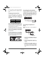
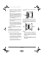
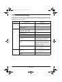
1
32-2003.fm Page 1 Tuesday, March 28, 2000 10:45 AM
Please read before using this equipment.
Owner’s Manual
MPA-125 100-Watt PA Amplifier
32-2003.fm Page 2 Tuesday, March 28, 2000 10:45 AM
ˆ Contents
Features .................................................................................................................................. 3
Preparation .............................................................................................................................
Presetting the Controls ......................................................................................................
Presetting Audio Input Devices ..................................................................................
Presetting the Amplifier ..............................................................................................
Mounting the Amplifier ......................................................................................................
Placing the Speakers ........................................................................................................
4
4
4
4
5
5
Connections ............................................................................................................................ 5
Connecting Input Sources ................................................................................................. 5
Connecting Microphones ........................................................................................... 5
Connecting a Turntable .............................................................................................. 6
Connecting an Auxiliary Sound Source ..................................................................... 7
Connecting the MIX BUS Jack ................................................................................... 7
Connecting an Equalizer ............................................................................................ 7
Connecting the Speakers .................................................................................................. 8
Determining Total Speaker Impedance ...................................................................... 8
Preparing the Speaker Wire ....................................................................................... 9
Connecting Only One Speaker .................................................................................. 9
Connecting Two Speakers In Series .......................................................................... 9
Connecting Two Speakers In Parallel ...................................................................... 10
Connecting Four Speakers In Series/Parallel Combination ..................................... 10
Connecting Speakers with Transformers ................................................................. 11
Connecting Power ........................................................................................................... 12
Using Your Amplifier ........................................................................................................ 12
Safety Indicators ............................................................................................................. 13
Monitoring the Sound Sources ........................................................................................ 13
Listening Safely ....................................................................................................... 13
Using an Equalizer .......................................................................................................... 13
Using the Feedback Filter ............................................................................................... 14
Troubleshooting ................................................................................................................... 15
Care and Maintenance ......................................................................................................... 16
Replacing the Fuse ......................................................................................................... 17
The FCC Wants You to Know ......................................................................................... 17
Specifications ....................................................................................................................... 18
© 2000 Tandy Corporation.
All Rights Reserved.
RadioShack and RadioShack.com are trademarks used by Tandy Corporation.
2
32-2003.fm Page 3 Tuesday, March 28, 2000 10:45 AM
ˆ Features
Your RadioShack MPA-125 100-Watt PA
Amplifier gives you the versatility and power
you need in a professional sound system. Its
wide frequency response easily handles amplification of voice and music. Use it in meeting halls and auditoriums, at sports events, in
schools, and in the office for paging systems
– anywhere you need to deliver special announcements with excellent sound.
Your amplifier includes these features:
100-Watt Output — provides powerful audio
output for many types of sound installations.
60–25000 Hz Frequency Response — provides wide-ranging response for true audio
reproduction.
Lighted VU Meter — measures the amplifier’s output in decibels.
Two Mounting Options — you can mount
the amplifier in a standard-sized audio equipment rack or on a desk, shelf, or table.
Master Volume Control — lets you adjust
the overall sound level.
EQ IN/OUT Switch — lets you connect and
use an equalizer with the amplifier.
Push-Terminal Connectors — let you easily connect wires directly to the amplifier.
Five Individual Source Mixing Controls —
let you mix connected sound sources individually or all at the same time.
Feedback Filter — lets you control audio
feedback.
Read this manual carefully. It describes various speaker connections to help you select
the best arrangement for your amplifier and
connected equipment, and explains how to
use the amplifier.
WARNING: To reduce the risk of fire or shock hazard, do not expose this product to rain or moisture.
Clipping Indicator — lights when a sound
source signal exceeds its mixing control setting.
CAUTION
RISK OF ELECTRIC SHOCK.
DO NOT OPEN.
!
CAUTION: TO REDUCE THE RISK OF
Overload Protection — automatically interrupts the amplifier’s power and lights an indicator if the amplifier gets too hot due to
power overload.
ELECTRIC SHOCK, DO NOT REMOVE
COVER OR BACK. NO USER-SERVICEABLE
PARTS INSIDE. REFER SERVICING TO
QUALIFIED PERSONNEL.
Four Microphone Input Jacks — you can
connect up to four balanced or unbalanced
microphones to the amplifier.
This symbol is intended to alert you to
the presence of uninsulated dangerous voltage within the product’s enclosure that might be of sufficient
magnitude to constitute a risk of electric shock. Do not open the product’s
case.
CD/Auxiliary Input Jack — you can connect
a variety of audio input sources for music
and special effects.
Phones Jack — you can connect headphones so you can hear the mixed audio in
privacy.
Features
!
This symbol is intended to inform you
that important operating and maintenance instructions are included in the
literature accompanying this product.
3
32-2003.fm Page 4 Tuesday, March 28, 2000 10:45 AM
ˆ Preparation
PRESETTING THE CONTROLS
Before you begin making connections or using your amplifier, preset the audio input source’s
and the amplifier’s controls to avoid over-driving a channel or producing sudden unexpected
loud sounds.
Presetting Audio Input Devices
Set the audio input sources’ controls to these levels:
Audio Device
Control
Setting
Turntable
Power
Off
Tape Deck
Power
Off
CD Player
Power
Off
Amplifier/Receiver
Power Tone
Off Flat
Presetting the Amplifier
Warning: To prevent possible hearing loss, set the amplifier’s controls to the settings shown
below. After you turn on the amplifier or change the program source, adjust the controls to a
comfortable listening level.
Set the amplifier’s controls to these levels:
Control
POWER
4
Setting
POWER
Out
MIC 1, MIC 2, MIC 3, MIC 4/PHONO, CD AUX
MIN
MASTER VOLUME
MIN
MIC 1
MIC 2
MIC 3
MIC 4/PHONO
Preparation
CD/AUX
MASTER VOLUME
32-2003.fm Page 5 Tuesday, March 28, 2000 10:45 AM
MOUNTING THE AMPLIFIER
PLACING THE SPEAKERS
You can mount the amplifier in a standardsized audio equipment rack or on a desk,
shelf, or table. Be sure you place it in a location with adequate ventilation. Do not put it
on thick carpeting (which can restrict air flow)
or near a heat source such as a heat vent or
radiator (which can cause it to overheat).
Speaker placement depends on your room’s
size and arrangement. We recommend you
play a wide-range recording and experiment
with speaker placement until you find the locations that result in the best sound. For the
best results, point the speakers in toward the
listeners, especially if you place speakers far
apart so their coverage areas overlap to prevent dead spots (areas not covered by the
speakers’ sound). Position the speakers
slightly above the level of the listeners’
heads (see “Connecting the Speakers” on
Page 8).
ˆ Connections
CONNECTING INPUT SOURCES
You can connect optional components such as microphones, a tuner, a turntable, or a CD player to your amplifier to expand your audio system. To prevent hum and other noise, use low-capacitance shielded cable. Your local RadioShack store carries a wide selection of audio
components and cable.
Before you make any connections, be sure POWER on the front of the amplifier is out and the
AC power cord is not plugged in.
Connecting Microphones
You can connect up to four high- or low-impedance microphones to the microphone inputs on
the back of the amplifier. Each input (labeled MIC 1, MIC 2, MIC 3, and MIC 4) has a balanced
and unbalanced jack. You need a microphone cord with a 1/4-inch (6.35-mm) plug to connect to
an unbalanced jack or a microphone cord with a 3-pin XLR plug to connect to a balanced jack.
1/4 -Inch Plug
3-Pin XLR Plug
Connections
MIC 4
MIC 3
MIC 2 MIC 1
MIC 4 MIC 3 MIC 2
MIC 1
5
32-2003.fm Page 6 Tuesday, March 28, 2000 10:45 AM
Notes:
• If your microphone’s cord is longer than 20 feet (6.01 meters), we recommend that you
connect it to a balanced jack to reduce signal hum.
• If you connect a microphone to both jacks for MIC 1, MIC 2, MIC 3, or MIC 4, the microphone
you connect to the unbalanced jack has priority.
• If you connect a microphone to either MIC 4 jack, set PHONO/MIC 4 on the back of the
amplifier to MIC 4.
Connecting a Turntable
Turntable
GND
PHONE/MIC 4
You can connect a low-level audio input source (such as a magnetic cartridge turntable) to the
L PHONO and R PHONO jacks on the back of the amplifier.
If you connect a low-level audio input source to the PHONO jacks, set PHONO/MIC 4 on the back
of the amplifier to PHONO.
To avoid a low-frequency hum, connect your turntable’s ground wire (usually black or green) to
the amplifier’s GND terminal.
6
Connections
32-2003.fm Page 7 Tuesday, March 28, 2000 10:45 AM
Connecting an Auxiliary Sound Source
You can connect any high-level sound source, such as a CD player, tape deck, or tuner, to the
CD/AUX jack on the back of the amplifier.
CD/AUX
Connecting the MIX BUS Jack
You can connect another MPA-125 to this jack to double the size of your PA system. This lets
you use up to eight microphones (or six microphones and two turntables), and two auxiliary
sound sources.
Use a shielded cable with phono plugs at each end, and connect the cable between the MIX
BUS jacks on the back of the two amplifiers. For the best results, do not use a cable longer than
6 feet.
MIX BUS Jack
Connecting an Equalizer
You can connect an equalizer or other external signal processor to the EQ IN and EQ OUT jacks
on the back of the amplifier.
EQ IN/OUT
Note: You can also connect a tape deck to the EQ OUT jack for recording.
Connections
7
32-2003.fm Page 8 Tuesday, March 28, 2000 10:45 AM
CONNECTING THE
SPEAKERS
Determine the total impedance of
speakers you want to connect in series
by adding up the individual impedances
of all the connected speakers. For
example, if you want to connect two 8ohm speakers in series, add 8 (the
impedance of one speaker) plus 8 (the
impedance of the other speaker) for a
total speaker impedance of 16 ohms
(see “Connecting Two Speakers In
Series” on Page 9).
You can connect one or more 4-, 8- or 16ohm speakers to the amplifier, with or without transformers. To ensure equal volume
from each speaker, all connected speakers
should have the same impedance rating.
Proper phasing is important when you use
more than one speaker in the same room or
area. Out-of-phase speakers can lose up to
one-half of their potential volume, and can
have a significantly decreased bass effect.
Most speaker terminals are color-coded or
have a mark that indicates the terminal’s polarity. Usually, terminals with positive polarity
are red or have a plus symbol (+), and terminals with negative polarity are black or have
a minus symbol (–). Phasing is correct when
you connect + to + and – to –.
• Speakers are connected in parallel
when all the speakers’ negative terminals are connected together and all their
positive terminals are connected
together.
Determine the total impedance of
speakers you want to connect in parallel
by dividing the impedance of one
speaker by the number of speakers. For
example, if you plan to connect two 8ohm speakers in parallel, divide 8 (the
impedance of one speaker) by 2 (the
number of speakers) for a total speaker
impedance of 4 ohms (see “Connecting
Two Speakers In Parallel” on Page 10).
Determining Total Speaker
Impedance
Before you connect speakers to the amplifier, you must determine the total speaker impedance.
Caution: A total speaker impedance higher
than 16 ohms or lower than 4 ohms can
damage your amplifier or speakers.
In determining the total speaker impedance,
you must first determine if you are connecting the speakers in series, parallel, or a series/parallel combination.
• If you are connecting more than two
speakers using only series or only parallel connections, the total impedance
might exceed the amplifier’s maximum
impedance (16 ohms) or fall below its
minimum impedance (4 ohms).
For example, if you connect four 8-ohm
speakers:
Note: For the best results when connecting
speakers (in series or parallel), only use
speakers that have the same impedance.
• In series, the total impedance is 32
ohms (8 + 8 + 8 + 8 = 32). This
exceeds the maximum rating.
• Speakers are connected in series when
the first speaker’s positive terminal is
connected to the next speaker’s negative terminal.
• In parallel, the total impedance is 2
ohms (8 divided by 4 = 2). This falls
below the minimum rating.
8
Connections
32-2003.fm Page 9 Tuesday, March 28, 2000 10:45 AM
You can achieve a proper total impedance
by combining series and parallel connections.
Preparing the Speaker Wire
Use the shortest length of wire possible to
connect the speakers. After placing the
speakers, use this table to determine the
wire length and choose the appropriate
gauge size:
Wire Length
Connecting Only One Speaker
Connect the speaker’s negative (–) terminal
to COM (common) on the back of the amplifier. Then connect the speaker’s positive (+)
terminal to the speaker terminal (4Ω, 8Ω, or
16Ω) on the back of the amplifier that matches the speaker’s impedance.
Wire Gauge
25 feet or less
18 gauge
Over 25 feet
16 gauge
8Ω
Ω Speaker
Note: If you connect speakers without transformers, the speaker wire should be no longer than 50 feet (see “Connecting Speakers
with Transformers” on Page 11).
To prepare the speaker wire, remove about 1
inch of insulation from the end of the speaker
wire you are connecting to the amplifier.
Then twist the exposed wire to secure all of
the wire strands.
Connecting Two Speakers In
Series
Follow these steps to connect speakers in
series.
To connect speaker wire to the amplifier,
press the push terminal lever on the amplifier
for the connector you want, insert the end of
the wire into the terminal’s hole, then release
the lever to secure the wire.
Left Speaker
Right Speaker
1. Connect the left speaker’s positive (+)
terminal to the right speaker’s negative
(–) terminal.
Terminal Levers
2. Connect the left speaker’s negative (–)
terminal to COM on the back of the
amplifier.
3. Connect the right speaker’s positive (+)
Ω,
terminals to the speaker terminal (4Ω
8Ω, or 16Ω) on the back of the amplifier
that matches the total speaker impedance.
Connections
9
32-2003.fm Page 10 Tuesday, March 28, 2000 10:45 AM
Connecting Two Speakers In Parallel
Follow these steps to connect speakers in parallel.
Two 8Ω
Ω Speakers
8Ω
Ω
___________
= 4Ω
Ω
2 Speakers
8Ω
Ω
8Ω
Ω
Speaker 1
Speaker 2
1. Connect both speaker’s negative (–) terminals to each other, then connect both wires to
the COM terminal on the back of the amplifier.
2. Connect both speaker’s positive (+) terminals to each other, then connect both wires to the
Ω, 8Ω, or 16Ω) on the back of the amplifier that matches the total
speaker terminal (4Ω
speaker impedance.
Connecting Four Speakers In Series/Parallel Combination
Follow these steps to combine series and parallel connections.
8Ω
Ω
Ω of 1 Pair
No. of Pairs
8Ω
Ω
= Total Ω
8Ω
Ω
16W = 8Ω
Ω
2
8Ω
Ω
1. Group the four speakers into two pairs.
2. Connect each pair of speakers in series. If you connected 8-ohm speakers, the total
impedance of each pair is 16 ohms (8 + 8 = 16).
10
Connections
32-2003.fm Page 11 Tuesday, March 28, 2000 10:45 AM
3. Connect the two pairs of speakers in
parallel. If you connected 8 ohm speakers the total impedance of both pairs is 8
ohms (16 ÷ 2 = 8).
Note: If each of the four speakers is 8
ohms, the total speaker impedance of
the combined series/parallel connection
described above is also 8 ohms. Likewise, the total speaker impedance is 4
or 16 ohms if the speakers are 4 or 16
ohms, respectively.
4. Connect the speakers’ negative (–) terminals to the COM terminal on the back
of the amplifier.
5. Connect the speaker’s positive (+) terΩ, 8Ω,
minals to the speaker terminal (4Ω
or 16Ω) on the back of the amplifier that
matches the total speaker impedance as
calculated in Step 3.
Connecting Speakers with Transformers
For the best results when you connect two or
more speakers to your system, use a line
transformer (not supplied) for each speaker.
Transformers offer these advantages:
• You can connect speakers with different
impedances without causing differences in output between the speakers.
• You can add or remove a speaker from
the system without having to recalculate
the entire system’s impedance.
Line transformers have several connectors
called taps.
Taps
The primary taps (on one side of the transformer) are the inputs and are rated in watts.
The secondary taps (on the opposite side of
the transformer) are the outputs and are rated in ohms.
Primary
Taps
Secondary
Taps
Cautions:
• Before you connect the speakers, be
sure the total wattage of the primary tap
you intend to use does not exceed the
amplifier’s maximum 100-watt output
power rating.
• Avoid multiple connections to the 70V
RMS and COM terminals on the back of
the amplifier.
• You can reduce signal loss when you
use speaker wire over 50 feet long.
Connections
11
32-2003.fm Page 12 Tuesday, March 28, 2000 10:45 AM
Follow these steps to connect speakers using a transformer.
Connect a wire from 70V RMS on the back of
the amplifier to the transformer’s desired primary tap (10, 5, 2.5, 1.25 or 0.62 watts).
USING YOUR AMPLIFIER
Note: Usually, each speaker in a system
uses the same wattage tap. If you want a
particular speaker to have a higher volume
level, connect the wire from 70V RMS to a
higher wattage tap on the transformer.
Start the input sound source.
Connect a wire from COM on the back of the
amplifier to the C (common) taps on the
transformer’s primary side.
Connect a wire from the speaker’s positive
(+) terminal to the transformer’s secondary
tap that matches the speaker’s total impedance (4 ohms, 8 ohms, or 16 ohms).
Connect a wire from the speaker’s negative
(–) terminal to the C (common) tap on the
transformer’s secondary side.
Press in POWER to turn on the amplifier.
Rotate MASTER VOLUME to its mid-position.
One at a time, adjust MIC 1, MIC 2, MIC 3, MIC
4/PHONO, and CD/AUX to the desired volume
and balance.
Note: If you hear feedback after you adjust
these controls, turn FEEDBACK FILTER clockwise until the noise disappears (see “Using
the Feedback Filter” on Page 14).
After you get the desired balance, adjust
MASTER VOLUME to the desired volume level.
CONNECTING POWER
To connect the amplifier to power, plug its
power cord into a standard AC outlet.
Your amplifier’s fuse (located on the amplifier’s back panel) protects the amplifier from
voltage surges. If the PROTECTION indicator does not light when you press POWER
(see “Using Your Amplifier” and “Safety Indicators” on Page 13), check the fuse. If it is
blown, see “Replacing the Fuse” on Page 17.
12
Connections
32-2003.fm Page 13 Tuesday, March 28, 2000 10:45 AM
SAFETY INDICATORS
Your amplifier has two indicators that warn you of potential damage to the amplifier.
CLIPPING Indicator
PROTECTION Indicator
The CLIPPING indicator lights when a sound source’s signal exceeds its mixing control setting.
If this happens, reduce the level of the appropriate mixing control or reduce MASTER VOLUME
until the indicator flickers only at peak volume levels.
The PROTECTION indicator lights if the amplifier gets too hot because of a power overload.
The amplifier’s built-in protection circuit temporarily interrupts the amplifier’s power. If this happens, press POWER to turn off the amplifier, let the amplifier cool for about 15 minutes, and correct whatever caused the overload. Then press POWER again to turn on the amplifier.
Note: If the power does not immediately come on, turn off the power again, wait about 5 more
minutes, then press POWER again.
MONITORING THE SOUND
SOURCES
• Do not listen at extremely high volume
levels. Extended high-volume listening
can lead to permanent hearing loss.
To monitor the sound sources, plug a pair of
mono or stereo headphones (not supplied)
with a 1/4-inch (6.35-mm) plug into the
PHONES jack on the front of the amplifier.
Using headphones lets you easily check and
adjust the sound source’s balance. Your local RadioShack store carries a wide selection of headphones.
• Once you set the volume, do not
increase it. Over time, your ears adapt
to the volume level, so a volume level
that does not cause discomfort might
still damage your hearing.
USING AN EQUALIZER
If you connected an equalizer, set EQ/BYPASS on the back of the amplifier to EQ.
Listening Safely
To protect your hearing, follow these guidelines when you use headphones.
• Set the volume to the lowest setting
before you begin listening. After you
begin listening, adjust the volume to a
comfortable level.
Note: If the equalizer has a bypass switch,
be sure it is set to OUT or turned off. Otherwise, the equalizer has no effect on your system’s sound.
Connections
13
32-2003.fm Page 14 Tuesday, March 28, 2000 10:45 AM
USING THE FEEDBACK FILTER
The FEEDBACK FILTER control lets you reduce or eliminate squeal and other noise caused by
feedback.
After you adjust MASTER VOLUME, MIC 1, MIC 2, MIC 3, MIC 4/PHONO, and CD/AUX, turn on the
amplifier and any connected sound source. If you hear any feedback, turn FEEDBACK FILTER
clockwise until you reduce or eliminate the feedback.
Note: The FEEDBACK FILTER control decreases feedback frequencies by up to 12 dB. If it does
not eliminate the feedback, try using a frequency equalizer to further decrease the feedback
frequencies.
FEEDBACK FILTER
14
Connections
32-2003.fm Page 15 Tuesday, March 28, 2000 10:45 AM
ˆ Troubleshooting
We do not expect you to have any problems with your RadioShack MPA-125 100-Watt PA Amplifier, but if you do have a problem, this chart might help. If not, take the amplifier to your local
RadioShack store for assistance.
Symptom
No power.
No sound.
Feedback.
Possible Cause
Suggestion
The fuse might be blown.
Check the amplifier’s fuse and replace it
if necessary (see “Replacing the Fuse”
on Page 17).
Sound source or speakers not connected correctly.
Check all connections.
Amplifier’s MASTER VOLUME, MIC 1,
MIC 2, MIC 3, MIC 4/PHONO, or CD/
AUX controls set to minimum.
Adjust MASTER VOLUME, MIC 1, MIC
2, MIC 3, MIC 4/PHONO, and CD/AUX.
Sound source or speakers not connected correctly.
Check all connections.
A microphone or cable might be faulty.
Check all microphones and cables.
The speaker’s wiring might be shorted.
Check all connections.
The speakers might be the wrong
impedance.
Make sure all connected speakers have
the same impedance rating (see “Connecting the Speakers” on Page 8).
The speaker’s wires might be too
small.
Make sure the speaker’s wires are 18gauge (for wire lengths up to 25 feet) or
16-gauge (for lengths over 25 feet). For
the best results, use the shortest length
of speaker wire possible.
The amplifier might have shut down.
Turn the amplifier off and let it cool.
Make sure the amplifier is properly ventilated, then turn it back on.
FEEDBACK FILTER might need
adjustment.
Turn the amplifier off and let it cool.
Make sure the amplifier is properly ventilated, then turn it back on.
Microphones or speakers are too close
together.
Reposition the microphones and speakers.
Troubleshooting
15
32-2003.fm Page 16 Tuesday, March 28, 2000 10:45 AM
ˆ Care and Maintenance
Your RadioShack MPA-125 100-Watt PA Amplifier is an example of superior design and
craftsmanship. The following suggestions will help you care for your amplifier so you can enjoy it for years.
Keep the amplifier dry. If it gets wet, wipe it dry immediately. Liquids might contain minerals that can corrode the electronic circuits.
Use and store the amplifier only in normal temperature environments. Temperature extremes can shorten the life of electronic devices and distort or melt
plastic parts.
Keep the amplifier away from dust and dirt, which can cause premature wear of
parts.
Handle the amplifier gently and carefully. Dropping it can damage circuit boards
and cases and can cause the amplifier to work improperly.
Wipe the amplifier with a damp cloth occasionally to keep it looking new. Do not
use harsh chemicals, cleaning solvents, or strong detergents to clean the amplifier.
Modifying or tampering with the amplifier’s internal components can cause a malfunction and
might invalidate its warranty. If your amplifier is not performing as it should, take it to your local RadioShack store for assistance.
16
Care and Maintenance
32-2003.fm Page 17 Tuesday, March 28, 2000 10:45 AM
REPLACING THE FUSE
If the amplifier does not operate, you might
need to replace the fuse on the back of the
amplifier with the supplied (or another) 3amp, 250-volt fuse.
Important: Let the amplifier cool down and
see if it starts again before you assume a
fuse needs to be replaced.
Caution: Do not use a fuse with ratings other
than those specified. Doing so might damage
your amplifier.
1. Unplug the amplifier.
2. Use a Phillips screwdriver to remove the
fuse holder cap on the back of the amplifier, then pull out the cap to remove the
fuse.
3. If the fuse is blown, replace it.
4. Insert the fuse into the fuse holder’s
socket, press the fuse holder back into
the amplifier, then use a Phillips screwdriver to replace the fuse holder cap.
THE FCC WANTS YOU TO
KNOW
Your amplifier might cause TV or radio interference even when it is operating properly.
To determine whether your amplifier is causing the interference, turn off your amplifier. If
the interference goes away, your amplifier is
causing it. Try to eliminate the interference
by:
• moving your amplifier away from the
receiver
• contacting your local RadioShack store
for help
Care and Maintenance
17
32-2003.fm Page 18 Tuesday, March 28, 2000 10:45 AM
ˆ Specifications
Output Power at THD 2%, 8 Ohm Load 1 kHz ................................................................................... 100 W
Total Harmonic Distortion (at 70 Watts, 8 ohms, 1 kHz, with Band Pass Filter)
MIC (Phone Jack) .......................................................................................................................
MIC (XLR Jack) ..........................................................................................................................
CD/AUX ......................................................................................................................................
PHONO ......................................................................................................................................
0.25%
0.35%
0.20%
0.25%
Input Sensitivity (at 2% THD, 1 kHz)
MIC (Phone Jack) .................................................................................................................... 1.35 mV
MIC (XLR Jack) ............................................................................................................................ 1 mV
CD/AUX .................................................................................................................................... 150 mV
PHONO ..................................................................................................................................... 2.8 mV
Signal to Noise Ratio (Input Shorted) with WTD
MIC (Phone Jack) ........................................................................................................................
MIC (XLR Jack) ...........................................................................................................................
CD/AUX .......................................................................................................................................
PHONO .......................................................................................................................................
60 dB
54 dB
73 dB
60 dB
Frequency Response (at 1 Watt, +/– 3 dB)
MIC (Phone Jack) ........................................................................................................... 60 Hz–20 kHz
MIC (XLR Jack) .............................................................................................................. 60 Hz–20 kHz
CD/AUX .......................................................................................................................... 60 Hz–20 kHz
PHONO (RIAA 100 Hz/10 kHz) ................................................................................. +12 dB/–12.5 dB
Notch Filter Effect
Range ............................................................................................................................. 300 Hz–3 kHz
Depth ......................................................................................................................................... –12 dB
Noise Level (Input Short) ................................................................................................................. 0.75 mV
Power Requirements ........................................................................................................... 120V AC 60 Hz
3
15
15
Dimensions (HWD) ....................................................................................... 4 /16 × 18 /16 × 11 /16 Inches
(10.0 × 48.2 × 27.3 cm)
Weight .............................................................................................................................................. 22.3 lbs
(10.1 kg)
Specifications are typical; individual units might vary. Specifications are subject to change and improvement without notice.
18
Specifications
32-2003.fm Page 19 Tuesday, March 28, 2000 10:45 AM
ˆ Notes
Notes
19
32-2003.fm Page 20 Tuesday, March 28, 2000 10:45 AM
Limited One-Year Warranty
This product is warranted by RadioShack against manufacturing defects in material and workmanship under normal use for one (1) year from the date of purchase from RadioShack company-owned
stores and authorized RadioShack franchisees and dealers. EXCEPT AS PROVIDED HEREIN, RadioShack MAKES NO EXPRESS WARRANTIES AND ANY IMPLIED WARRANTIES, INCLUDING
THOSE OF MERCHANTABILITY AND FITNESS FOR A PARTICULAR PURPOSE, ARE LIMITED
IN DURATION TO THE DURATION OF THE WRITTEN LIMITED WARRANTIES CONTAINED
HEREIN. EXCEPT AS PROVIDED HEREIN, RadioShack SHALL HAVE NO LIABILITY OR RESPONSIBILITY TO CUSTOMER OR ANY OTHER PERSON OR ENTITY WITH RESPECT TO ANY
LIABILITY, LOSS OR DAMAGE CAUSED DIRECTLY OR INDIRECTLY BY USE OR PERFORMANCE OF THE PRODUCT OR ARISING OUT OF ANY BREACH OF THIS WARRANTY, INCLUDING, BUT NOT LIMITED TO, ANY DAMAGES RESULTING FROM INCONVENIENCE, LOSS
OF TIME, DATA, PROPERTY, REVENUE, OR PROFIT OR ANY INDIRECT, SPECIAL, INCIDENTAL, OR CONSEQUENTIAL DAMAGES, EVEN IF RadioShack HAS BEEN ADVISED OF THE
POSSIBILITY OF SUCH DAMAGES.
Some states do not allow limitations on how long an implied warranty lasts or the exclusion or limitation of incidental or consequential damages, so the above limitations or exclusions may not apply to
you.
In the event of a product defect during the warranty period, take the product and the RadioShack
sales receipt as proof of purchase date to any RadioShack store. RadioShack will, at its option, unless otherwise provided by law: (a) correct the defect by product repair without charge for parts and
labor; (b) replace the product with one of the same or similar design; or (c) refund the purchase
price. All replaced parts and products, and products on which a refund is made, become the property of RadioShack. New or reconditioned parts and products may be used in the performance of
warranty service. Repaired or replaced parts and products are warranted for the remainder of the
original warranty period. You will be charged for repair or replacement of the product made after the
expiration of the warranty period.
This warranty does not cover: (a) damage or failure caused by or attributable to acts of God, abuse,
accident, misuse, improper or abnormal usage, failure to follow instructions, improper installation or
maintenance, alteration, lightning or other incidence of excess voltage or current; (b) any repairs
other than those provided by a RadioShack Authorized Service Facility; (c) consumables such as
fuses or batteries; (d) cosmetic damage; (e) transportation, shipping or insurance costs; or (f) costs
of product removal, installation, set-up service adjustment or reinstallation.
This warranty gives you specific legal rights, and you may also have other rights which vary from
state to state.
RadioShack Customer Relations, 200 Taylor Street, 6th Floor, Fort Worth, TX 76102
We Service What We Sell
RadioShack
A Division of Tandy Corporation
Fort Worth, Texas 76102
12/99
32-2003
03A00
Printed in China