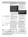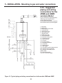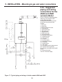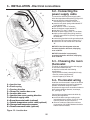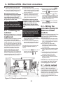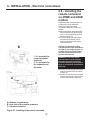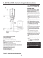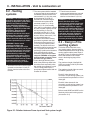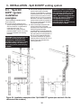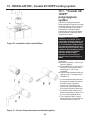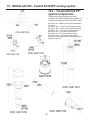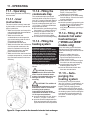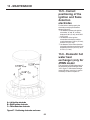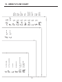
1
Installation and maintenance
instructions for gas-fired condensing
hot water boilers models:
ONEX
ASME
certified
INSTALLER, THESE INSTRUCTIONS TO BE AFFIXED ADJACENT TO THE BOILER.
62403466 R04 14/11/2008
(Book No. 62403466, Ed. Sep. 2008)
SAFETY INSTRUCTIONS
WARNING: If the information in these
instructions is not followed exactly, a fire
or explosion may result causing property
damage, personal injury or death.
AVERTISSMENT: Assurez vous de bien
suivre les instructions données dans
cette notice pour réduire au minimum le
risque d’incendie ou d’explosion ou pour
éviter tout dommage matériel, toute
blessure ou la mort
- Do not store or use gasoline or other
flammable vapors and liquids in the
vicinity of this or any other appliance.
- Ne pas entreposer ni utiliser d’essence ou
ni d’autres vapeurs ou liquides
inflammables à proximité de cette appareil
ou de tout autre appareil.
- WHAT TO DO IF YOU SMELL GAS
•
•
•
•
Do not try to light any appliance.
Do not touch any electrical switch; do
not use any phone in your building.
Immediately call your gas supplier from
a neighbor’s phone. Follow the gas
supplier’s instructions.
If you cannot reach your gas supplier,
call the fire department.
- QUE FAIRE SI VOUS SENTEZ UNE
ODEUR DE GAZ:
•
•
•
- Installation and service must be
performed by a qualified installer, service
agency or the gas supplier.
•
Ne pas tenter d’allumer l’appareil.
Ne touchez à aucun interrupteur, ne
pas vous servir des téléphones se
trouvant dans le bâtiment
Appelez immédiatement votre
fournisseur de gas de puis un voisin.
Suivez les instructions du fournisseur.
Si vous ne pouvez rejoindre le
fournisseur, appelez le service des
incendies
- L’installation et l’entretien doivent être
assurés par un installateur ou un service
d’entretien qualifié ou par le fournisseur
de gaz.
2
SAFETY INSTRUCTIONS
3
SAFETY INSTRUCTIONS
In the event of a breakdown and/or malfunction of
WARNING!!! These instructions must be read prior
to installation. If the information in these
instructions is not followed exactly, a fire or
explosion may result, causing property damage,
personal injury, or death.
the boiler, turn off the unit and do not make any
attempt to repair it. The boiler must be serviced
exclusively by a qualified technician using original spare
parts. Failure to comply with this requirement may
compromise the safety of the unit and void its warranty.
Liability
Use the service switch to disconnect the boiler
The manufacturer declines all liability, contractual or
otherwise, for damages resulting from the incorrect
installation of this boiler. This includes the failure to
comply with the instructions provided by the
manufacturer or from a failure to comply with the
applicable local and national regulations in force.
The manufacturer declines all liability, contractual or
otherwise, for any damage to people, animals or
property caused by the incorrect use of this boiler or
inadequate or incorrect service or maintenance.
from the electrical circuit before carrying out any
service or maintenance operations.
Electrical
CAUTION: Label all wires prior to disconnection when
servicing controls. Wiring errors can cause improper and
dangerous operation. Verify proper operation after
servicing.
ATTENTION: Au moment de l’entretien des
Hazards and Your Safety - Hot Water Can Scald!
commandes, étiquetez tous les fils avant de les
débrancher. Des erreurs de câblage peuvent entraîner
un fonctionnement inadéquat et dangereux. S’assurer
que l’appareil fonctionne adéquatement une fois
l’entretirn terminé.
Water temperature over 125°F (52°C) can cause severe
burns instantly, or death from scalds. Children, the
disabled, and the elderly are at highest risk of being
scalded; see instruction manual before setting
temperature at boiler! Feel water before bathing or
showering.
Correct Use:
This boiler must only be used for the purpose for which
it has been expressly designed: heating of water for
closed circuit systems for central heating and the
production of domestic hot water.
If there is a smell of combustion products, turn the
unit off, air out the room and call a licensed authorized
technician. Failure to take proper precautions can
result in excessive levels of carbon monoxide which
can cause severe personal injury or death!
Should overheating occur or the gas supply fail
to shut off, do not turn off or disconnect the electrical
supply to the pump. Instead, shut off the gas supply at
a location external to the appliance.
Qualified Technicians:
Qualified technicians are individuals with specific,
technical training in space heating systems, domestic
hot water systems, fuel gas systems and electrical
systems. These individuals must have the legally
required qualifications.
En cas de surchauffe ou si l’alimentation de gaz
ne peut être coupée, ne pas couper ni débranch
l’alimentation électrique de la ponpe. Fermer plutôt le
robinet d’admission de gaz à l’extérieur de l’appareil
Installation and Alterations:
Licensed, authorized personnel must carry out the
installation and calibration of the boiler. Never modify the
boiler or its flue gas carrying components in any way.
This boiler must be properly vented. Failure to follow
these instructions could result in personal injury or
death!
Do not use this appliance if any part has been
under water. Immediately call a qualified service
technician to inspect the appliance and to replace any
part of the control system and any gas control, which
has been under water.
For safety and environmental reasons, the packing
N’utilisez pas cet appareil s’il a été plongé dans
l’eau, même partiellement. Faites inspecter l’appareil
par un tecnicien qualifié et remplacez toute partie du
système de contrôle et toute commande qui ont été
plongés dans l’eau.
materials must be properly disposed of. Any replaced
part or packaging should never be left within the reach of
children. Failure to follow these instructions could result
in severe personal injury
Maintenance:
Do not obstruct the air intake or vent pipe
terminals. Failure to take proper precautions can result
in excessive levels of carbon monoxide which can cause
severe personal injury or death!
at least once a year the user must call in a licensed
authorized technician for routine maintenance.
Any optional extras or kit fitted subsequently
must be original Cosmogas spares.
4
TABLE OF CONTENTS
SAFETY INSTRUCTIONS ........................................................................................................................................................................ 2
TABLE OF CONTENTS ........................................................................................................................................................................... 5
1 - INSTALLATION - CODE REQUIREMENTS ......................................................................................................................................... 7
1.1 - National installation legislation ............................................................................................................................................... 7
2 - GENERAL INFORMATION .................................................................................................................................................................. 8
2.1 - Introduction .............................................................................................................................................................................. 8
2.2 - Manufacturer ............................................................................................................................................................................ 8
2.3 - Key to symbols used ............................................................................................................................................................... 8
2.4 - Description of models ............................................................................................................................................................. 8
3 - MAIN COMPONENTS ........................................................................................................................................................................ 9
4 - FUNCTION OVERVIEW ................................................................................................................................................................... 11
4.1 - Intended use and functions of the boiler ............................................................................................................................... 13
4.2 - Setting of the boiler ................................................................................................................................................................ 13
4.3 - A smart and intelligent boiler ................................................................................................................................................. 14
4.4 - Characteristic curves of heating system’s residual head .................................................................................................... 15
4.5 - Boiler head loss curve ........................................................................................................................................................... 15
4.6 - Characteristic curve of the domestic side ............................................................................................................................. 15
5 - INSTALLATION - Mounting & gas and water connections .......................................................................................................... 16
5.1 - Clearances for installation and servicing for models ........................................................................................................... 16
5.2 - Clearances from combustible material ................................................................................................................................ 16
5.3 - Choosing the installation location for 45WN and 45AN models .......................................................................................... 16
5.4 - Choosing the installation location for 45WE and 45AE models .......................................................................................... 17
5.5 - Mounting the boiler ................................................................................................................................................................ 18
5.5 - Mounting the casing in a 45WE or 45AE boiler ......................................................................................................... 18
5.6 - Gas and water connections .................................................................................................................................................. 18
5.7 - Condensate disposal ............................................................................................................................................................ 19
5.8 - Relief valve ............................................................................................................................................................................. 19
5.9 - Supply and return piping ....................................................................................................................................................... 20
5.10 - Low temperature heating systems ..................................................................................................................................... 20
5.11 - Use of glycol and other chemicals ...................................................................................................................................... 20
5.12 - Domestic hot and cold water (only for 45WN and 45WE models) ..................................................................................... 20
5.13 - Gas supply piping ................................................................................................................................................................ 21
5.14 - Operating at high altitudes .................................................................................................................................................. 21
5.15 - Suggested piping and wiring connections for the 45WN and 45WE versions Boiler ....................................................... 22
5.16 - Suggested piping and wiring connections for the 45AN and 45AE versions Boiler .......................................................... 23
6 - INSTALLATION - Electrical connections ....................................................................................................................................... 24
6.1 - Electrical connections: overview ........................................................................................................................................... 24
6.2 - Connecting the power supply cable ...................................................................................................................................... 25
6.3 - Choosing the room thermostat ............................................................................................................................................. 25
6.4 - Thermostat wiring .................................................................................................................................................................. 25
6.5 - Installing the outdoor temperature sensor (optional) ........................................................................................................... 26
6.6 - Wiring the circulator pump for 45AN and 45AE models ....................................................................................................... 26
6.7 - Alarm output ........................................................................................................................................................................... 26
6.8 - Installing the remote command on 45WE and 45AE models .............................................................................................. 27
7 - INSTALLATION - Indirect storage tank connections ................................................................................................................... 28
7.1 - Connecting the boiler to an indirect storage tank ................................................................................................................. 28
8 - INSTALLATION - Vent & combustion air ....................................................................................................................................... 30
8.1 - Removing of a boiler from a common venting system ......................................................................................................... 30
8.2 - Venting systems .................................................................................................................................................................... 31
8.3 - Design of the venting system ................................................................................................................................................ 31
9 - INSTALLATION - Split 80/80PP venting system ............................................................................................................................ 32
9.1 - “Split 80/80PP” system (polypropylene) or AL29-4C (UL 1738/UL C 636) system .............................................................. 32
9.2 - “Split 80/80PP” system components ................................................................................................................................... 34
9.3 - “Split 80/80PP” system: installation examples ..................................................................................................................... 35
10 - INSTALLATION - Coaxial 60/100PP venting system .................................................................................................................. 36
10.1 - “Coaxial 60/100PP” polypropylene system ........................................................................................................................ 36
10.2 - “Coaxial 60/100 PP” system components .......................................................................................................................... 37
10.3 - “Coaxial 60/100PP” system: installation examples ......................................................................................................... 38
11 - OPERATING ................................................................................................................................................................................... 39
11.1 - Operating ............................................................................................................................................................................. 39
11.1.1 - User instructions ................................................................................................................................................... 39
11.1.2 - Filling the condensate trap .................................................................................................................................... 39
5
TABLE OF CONTENTS
11.1.3 - Filling the heating system ..................................................................................................................................... 39
11.1.4 - Filling of the domestic hot water heat exchanger (“45WN and 45WE” models only) .......................................... 39
11.1.5 – Auto-purging the heating system .......................................................................................................................... 39
11.2 - General warnings concerning gas supply .......................................................................................................................... 40
11.3 - Confirming the boiler’s gas type ......................................................................................................................................... 40
11.4 - Gas type conversion ............................................................................................................................................................ 40
11.5 - Start-up ................................................................................................................................................................................. 40
11.6 - Ignition control testing .......................................................................................................................................................... 40
11.7 - Gas supply pressure checking and adjustment ................................................................................................................. 41
11.8 - Check the combustion air pressure ................................................................................................................................... 42
11.9 - Checking and adjusting CO2 levels .................................................................................................................................... 43
11.9.1 - Checking and adjusting CO2 levels without CO2 meter ...................................................................................... 43
11.10 - Adjusting the heating capacity ........................................................................................................................................... 44
11.11 - Domestic hot water flow rate adjustment (45WN and 45WE models only) ..................................................................... 44
11.12 - Cold start boiler ................................................................................................................................................................. 44
12 - USE ............................................................................................................................................................................................... 45
12.1 - Adjusting the domestic hot water temperature .................................................................................................................. 45
12.2 - Heating system temperature adjustment ........................................................................................................................... 45
12.3 - Heating system type selection ............................................................................................................................................ 45
12.4 - Climatic adjustment ............................................................................................................................................................ 45
12.4.1 - Climatic adjustment: applicable system .............................................................................................................. 45
12.4.2 - Climatic adjustment precautions .......................................................................................................................... 45
12.4.3 - Climatic adjustment: setting parameters ............................................................................................................. 46
12.4.4 - Climatic adjustment: zone adjustments ............................................................................................................... 46
12.4.5 - Climatic adjustment activation .............................................................................................................................. 46
12.4.6 – Climatic adjustment with room compensation ................................................................................................... 46
12.5 - Boiler switch settings .......................................................................................................................................................... 48
12.6 - Delays, alarms and protective actions ................................................................................................................................ 48
12.7 - Circulator pump and three way valve protection ................................................................................................................. 48
12.8 - Freeze protection ................................................................................................................................................................. 48
12.9 - Display in energy saving mode ........................................................................................................................................... 48
12.10 - “Users’ menu” ................................................................................................................................................................... 49
12.11 - “Installers’ menu” .............................................................................................................................................................. 50
12.12 - Diagnostics ....................................................................................................................................................................... 52
12.12.1 - Diagnostics: “L” lock-outs ................................................................................................................................... 53
12.12.2 - Diagnostics: “E” blocking errors ......................................................................................................................... 55
12.13 - Remote command for model 45WE and 45AE ................................................................................................................ 57
13 - MAINTENANCE ............................................................................................................................................................................. 58
13.1 - General precaution .............................................................................................................................................................. 58
13.2 - Removing the casing for models 45WN and 45AN ............................................................................................................ 59
13.3 - Removing the casing on models 45WE and 45AE ............................................................................................................ 60
13.3.1 - Installing the casing on models 45WE and 45AE ................................................................................................ 60
13.4 - Cleaning the burner and primary heat exchanger, flue gas side ...................................................................................... 61
13.5 - Correct positioning of the ignition and flame detection electrodes .................................................................................... 62
13.6 - Domestic hot water heat exchanger (only for 45WN model ............................................................................................... 62
13.7 - Condensate trap cleaning ................................................................................................................................................... 63
13.8 - Circulator pump motor replacement (only for 45WN and 45WE models) ......................................................................... 64
13.9 - Expansion tank pressure (only for 45WN and 45WE models) ........................................................................................... 64
13.10 - 3-way valve removal (only for 45WN and 45WE models) ................................................................................................. 65
13.11 - Draining the heating side of the boiler .............................................................................................................................. 66
13.12 - Draining the domestic hot water side of the boiler ........................................................................................................... 66
13.13 – Overrides .......................................................................................................................................................................... 66
13.13.1 - Auto-purging ........................................................................................................................................................ 66
13.13.2 - Fan ....................................................................................................................................................................... 66
13.13.3 – Minimum and maximum output ......................................................................................................................... 66
13.13.4 – Checking the flame current ................................................................................................................................ 66
13.14 - Water and flue temperature sensor .................................................................................................................................. 67
13.15 - Outdoor temperature sensor (optional) ............................................................................................................................ 67
13.16 - Functional wiring diagram ................................................................................................................................................. 68
13.17 - Multiwire wiring diagram ................................................................................................................................................... 69
14 - TECHNICAL DATA ......................................................................................................................................................................... 70
15 - SPARE PARTS .............................................................................................................................................................................. 71
16 - MENU’S FLOW CHART ................................................................................................................................................................. 76
6
1 - INSTALLATION - CODE REQUIREMENTS
1.1 - National
installation
legislation
- The installation must conform to the
requirements of the authority having
jurisdiction or, in the absence of such
requirements, to the latest edition of
the National Fuel Gas Code, ANSI
Z223.1/NFPA 54 and or CAN/CSA
B149.1, Natural Gas and Propane
Installation Code.
- Where required by the authority
having jurisdiction, the installation
must conform to the Standard for
Controls and Safety Devices for
Automatically Fired Boilers, ANSI/
ASME CSD-1
7
2 - GENERAL INFORMATION
2.1 - Introduction
Congratulations!
You have effectively purchased
one of the best boilers on the
market.
Each single part is built, tested and
assembled, with pride, at the
COSMOGAS factories, thereby
guaranteeing optimum quality
control.
Thanks to on-going research
carried out by COSMOGAS, this
product has been conceived and is
considered to be the best in its
class with regards to respect for
the environment. Great
importance is also given to the end
of the boiler’s useful life. All of its
components can easily be
separated into similar and
completely recyclable parts.
2.2 - Manufacturer
COSMOGAS srl
Via L. da Vinci 16
47014 - Meldola (FC)
ITALY
Tel. +39 0543 498383
Fax. +39 0543 498393
www.cosmogas.com
[email protected]
45
XX
2.3 - Key to
symbols used
WARNING!!! Failure to follow these
indications can causing an
explosion, extensive property
damage, severe personal injury or
death!
CAUTION!!!
Electrical caution! Risk of electric
shock: failure to observe this warning
may compromise the smooth running
of the appliance or cause serious
damage to individuals, animals or
property.
CAUTION!!!
General caution. Failure to observe this
warning may compromise the smooth
running of the appliance or cause
serious damage to individuals, animals
or property.
Operation symbol
Important indication symbol
2.4 - Description of
models
Spare parts are available from your
local authorized wholesale distributor.
For a location of the one nearest you
call 413 -564- 9538.
AN = heating only version, for inside installation
WN = combi version (space heating and instantaneous D.H.W.
production), for inside installation.
AE = heating only version, for outdoor installation
WE = combi version (space heating and instantaneous D.H.W.
production), for outdoor installation.
Modulating gas-fired, condensing hot water boiler, with sealed
combustion chamber and pre-mix burner, with maximum power input
of 160,000 Btu/hr (47 kW) and minimum of 30,000 Btu/hr (9 kW)
8
3 - MAIN COMPONENTS
1 - Automatic air vent
2 - Air intake and flue gas discharge fitting (venting system)
3 - U7 flue gas temp. sensor and flue safety switch
4 - Expansion tank (not present on 45AN and 45AE models)
5 - Air drum
6 - Air/gas mixer device
7 - U2 d.h.w. temp. sensor (not present on 45AN and 45AE models)
8 - Heating pressure switch (low water cut-off)
9 - Heating supply connection
10 - DHW connection (not present on 45AN and 45AE models)
11 - Gas inlet connection
12 - DCW connection (not present on 45AN and 45AE models)
13 - Heating return connection
14 - Power Control Board
15 - Openterm interface board (optional)
16 - Connection board
17 - Primary heat exchanger
18 - Spark cable
19 - External jacket
20 - Sealing chamber door
21 - Instrument panel door
Figure 1 - Main components
9
3 - MAIN COMPONENTS
22 - Combustion analysis tap
23 - U1 supply temperature sensor
24 - Burner window
25 - Air/gas manifold
26 - U6 high temperature limit sensor
27 - Flue gases back flow preventer
28 - Fan
29 - Gas valve
30 - Heating pressure gauge
31 - Display
32 - Domestic hot water temperature control
33 - Heating temperature control
34 - On/off power switch
35 - Three way valve (not present on 45AN
and 45AE models)
36 - U3 domestic cold water temp. sensor (not
present on 45AN and 45AE models)
37 - Cable clamp
38 - ASME Safety relief valve
39 - U8 return temperature sensor
40 - By-pass pipe (not present on 45AN and
45AE models)
41 - Condensation discharge pipe
42 - Secondary heat exchanger for domestic hot
water production (not present on 45AN and
models)
43 - Expansion tank connection pipe (not
present on 45AN and 45AE models)
44 - Circulator pump screw (not present on
45AN and 45AE models)
45 - Circulator pump (not present on 45AN and
45AE models)
46 - Condensation discharge trap
47 - Detection electrode
48 - Burner
49 - Right ignition electrode
50 - Left ignition electrode
51 - Spark generator
52 - Flue pressure switch
Figure 1 - Main components
10
4 - FUNCTION OVERVIEW
Key to figure 2:
1 = boiler model 45WN or 45WE
2 = automatic air vent
3 = air intake
4 = flue gases discharge
5 = sealed combustion chamber
6 = expansion tank
7 = burner
8 = fan
9 = gas valve
10 = condensate discharge trap
11 = circulator pump
12 = 3-way valve
13 = secondary heat exchanger for d.h.w.
14 = pressure gauge
15 = by-pass valve
17 = safety relief valve
21 = condensate discharge pipe
22 = heating supply pipe
23 = domestic hot water outlet
24 = gas inlet
25 = cold water inlet
26 = heating return pipe
45 = U7 = flue gas temperature sensor
46 = U1 = boiler temperature sensor
47 = U6 = high limit temperature sensor
48 = U3 = domestic cold water sensor/storage tank sensor
49 = U2 = domestic hot water temperature sensor
50 = U8 = return temperature sensor
51 = flue pressure switch
Figure 2 - 45WN and 45WE Hydronic functional schematic
11
4 - FUNCTION OVERVIEW
Key to figure 3:
1 = boiler model 45AN or 45AE
2 = automatic air vent
3 = air intake
4 = flue gases discharge
5 = sealed combustion chamber
7 = burner
8 = fan
9 = gas valve
10 = condensate discharge trap
14 = pressure gauge
17 = safety relief valve
20 = safety relief valve discharge
21 = condensation discharge pipe
22 = heating supply pipe
24 = gas inlet
26 = heating return pipe
45 = U7 = flue gas temperature sensor and high limit safety
switch
46 = U1 = boiler temperature sensor
47 = U6 = high limit temperature sensor
50 = U8 = return temperature sensor
51 = flue pressure switch
Figure 3 - 45AN and 45AE Hydronic functional schematic
12
4 - FUNCTION OVERVIEW
4.1 - Intended use
and functions of
the boiler
This gas-fired condensing boiler, is
designed to be used for central heating
and producing domestic hot water.
The maximum output heat is always
guaranteed for the production of
domestic hot water since it is given
priority over space heating demands.
Follow the specific procedure in
section 12.1 for the adjustment of the
domestic hot water temperature.
Depending on the model choosen, the
following system types can be created:
- 45WN. Using this boiler model, a
system can be created for the
production of instantaneous domestic
hot water and a heating system with
heating elements functioning at
temperatures ranging between 68°F
(20°C) and 189°F (87°C).
The boiler can also function directly
with a radiant floor panel, see section
5.9.
When connecting the boiler to the
heating system the installer must
consider the head loss of the heating
system to verify that the boiler pump is
adequate. Pump curve is shown in
figure 5. The same verification need to
be done for the domestic installation,
see figure 7.
- 45AN. Using this boiler model, a
heating system with heating elements
functioning at temperatures ranging
between 68°F (20°C) and 187°F (87°C)
can be configured.
The boiler can also function directly
with a radiant floor panel, see section
5.9.
The 45AN model is not equipped with
the components required for the
production of domestic hot water. Also
not included is the expansion tank and
circulator pump, see figure 3.
To connect the boiler to the heating
system, the installer must consider the
loss of pressure generated by the
boiler (see figure 6), and choose a
pump capable of overcoming the head
loss of both the boiler and the heating
system.
- 45WE. This boiler is equal to the
45WN model, but is intended for
outdoor installation.
- 45AE. This boiler is equal to the
45AN model, but is intended for
outdoor installation.
All models can be connected to an
indirect storage tank for the production
of domestic hot water, section 7.
All models can be connected to a
room thermostat, section 6.3 and 6.4.
Because boiler models 45WE and
45AE are usually installed outside the
building, they need to be connected to
a Remote Command, section 6.8.
An outdoor air temperature sensor can
also be connected to the boiler for
maximum fuel efficiency and comfort
(see section 6.5). In this configuration
the room thermostat will compensate
by adjusting the room temperature.
The room temperature compensation
can be of an ON /OFF type or twostage. For further information on the
Climatic heat adjustment, refer to
section 12.4.
The boiler must be connected to a
heating system and a domestic hot
water supply with compatible
specifications, performance and
power rating.
Before installation, thoroughly flush
the heating and plumbing systems
of any residue or impurities which
might compromise the smooth
running of the boiler.
Only boilers model 45WE and
45AE are designed for outdoor
installation. However also for these
boilers you need to choose a
sheltered place where it is
protected from atmospheric
elements including frost.
Refer to figure 8 for minimum
clearance distances for installation
13
and future maintenance.
Refer to section 5.2 for minimum
clearance distances from
combustible material.
4.2 - Setting of the
boiler
Inside this instruction manual there are
sections that require you to change the
settings of the boiler. To do this, the
installer needs to operate on several
available menus, which are explained
within the section the change is
needed.
To aid the installer, all menus are also
shown in section 16 with an
explanation of which varies keys to
press.
4 - FUNCTION OVERVIEW
4.3 - A smart and
intelligent boiler
When connected to an outside sensor
(optional), this boiler is designed to
always work at the maximum
efficiency. It will automatically change
the supply temperature in relation with
the outdoor temperature.
The graph in figure 4 shows an
example on how it can work.
This graph represent an installation
where the supply and return
temperatures are 139°F and 115°F
respectively , and the outside
temperature is 23°F. The outdoor
sensor drives the boiler, to
progressively reduce the supply
temperature and thereby optimize the
efficiency. It changes from 87% when
outside is -10°F, to 94.8% when
outside is 23°F and up to 98% when
the outside temperature rises up to
67°F.
Figure 4 - Relation between outdoor temperature, heating
temperature and efficiency
14
4 - FUNCTION OVERVIEW
4.4 - Characteristic
curves of heating
system’s residual
head
45WN and 45WE boilers are fitted with
its own specific circulator pump. The
residual head at the boiler connections
is shown in graph form in figure 5.
Figure 5 - Residual Head for heating circuit for models “45WN”
and “45WE”
4.5 - Boiler head
loss curve
45AN and 45AE boilers are not fitted
with an internal pump. The installer
needs to install an external pump as
illustrated in figure 17, item “6”. Use
the graph in figure 6 to choose the
correct pump.
Figure 6 - Boiler Head Loss for models “45AN” and “45AE”
4.6 - Characteristic
curve of the
domestic side
45WN and 45WE boilers, offers certain
resistance to the passage of the
domestic water (see graph flow/
pressure of figure 7). The installer or
the engineer must take account of this
in order to ensure the correct domestic
water flow to the utilities.
Figure 7 - Domestic Water Coil Head Loss for models “45WN”
and “45WE”
15
5 - INSTALLATION - Mounting & gas and water connections
5.1 - Clearances for
installation and servicing
for models
Figure 8 shows the clearances required for installation and
servicing.
NOTE: Service clearances are not mandatory, but are
recommended to ensure ease of service should it be
required.
5.2 - Clearances from
combustible material
This boiler may be installed directly onto a wall of
combustible material with the following clearance:
Ceiling:
2 inches (51 mm)
Front:
2 inches (51 mm)
Rear:
0 inches (0 mm)
Sides:
2 inches (51 mm)
Floor:
2 inches (51 mm)
Concentric vent:
0 inches (0 mm)
Split vent (first 12” from the boiler):
1 inch (25 mm)
Split vent (after 12” from the boiler):
0 inches (0 mm)
Figure 8 - Recommended minimum clearance
distances for proper installation and servicing for
models 45WN, 45AN, 45AE and 45WE.
5.3 - Choosing the
installation location for
45WN and 45AN models
CAUTION!!! The boiler must be installed on a
vertical wall constructed to bear its weight or the
boiler and building may be damaged.
NOTE: The boiler must never be installed on
carpeting.
CAUTION!!! This boiler is not designed for
1 = Area for power supply cable
2 = Heating supply connection (3/4”)
3 = Domestic hot water connection (3/4”)
(absent in 45AN model)
4 = Gas connection (3/4”)
5 = Domestic cold water connection (3/4”) (absent in
45AN model)
6 = heating return connection (3/4”)
7 = positions for boiler support
8 = Flue discharge/air intake connection
Figure 9 - Dimensions for models 45WN and 45AN
16
direct outdoor installation. If installed outside of the
structure that it supplies hot water too, it must be
sheltered so it is protected from rain, wind, sun and
frost. NEVER place this boiler in a location that would
subject it to temperatures at or near freezing. Failure
to properly locate this boiler can result in premature
failure voiding the warranty.
When locating the boiler the following factors must be
considered:
• the location of vent/air intake terminals;
• connection to the gas supply;
• connection to the water supply;
• connection to the heating system;
• connection to the domestic hot water system;
• connection to the electrical supply;
• disposal of the condensation produced by the boiler;
• connection to the room thermostat;
• piping of the safety relief valve discharge;
• possible connection of the outdoor temperature sensor;
• possible connection of an indirect storage tank, see
section 7.
5 - INSTALLATION - Mounting & gas and water connections
5.4 - Choosing the
installation location for
45WE and 45AE models
CAUTION!!! The boiler must be installed on a
vertical wall constructed to bear its weight or the
boiler and building may be damaged.
NOTE: The boiler must never be installed on
carpeting.
CAUTION!!! This boiler is designed also for
direct outdoor installation. However, if installed
outside of the structure that it supplies hot water too,
it must be sheltered so it is protected from rain, sun
and frost. NEVER place this boiler in a location that
would subject it to temperatures at or near freezing.
Failure to properly locate this boiler can result in
premature failure voiding the warranty.
When locating the boiler the following factors must be
considered:
• the location of vent/air intake terminals;
• connection to the gas supply;
• connection to the water supply;
• connection to the heating system;
• connection to the domestic hot water system;
• connection to the electrical supply;
• disposal of the condensation produced by the boiler;
• connection to the room thermostat;
• connection to the remote command;
• piping of the safety relief valve discharge;
• possible connection of the outdoor temperature sensor;
• possible connection of an indirect storage tank, see
section 7.
1 = Area for power supply cable
2 = Heating supply connection (3/4”)
3 = Domestic hot water connection (3/4”)
(absent in 45AE model)
4 = Gas connection (3/4”)
5 = Domestic cold water connection (3/4”) (absent in
45AE model)
6 = heating return connection (3/4”)
7 = positions for boiler support
8 = Flue discharge/air intake connection
Figure 10 - Dimensions for models 45WE and 45AE
17
5 - INSTALLATION - Mounting & gas and water connections
5.5 - Mounting the boiler
Refer to figure 11:
place the cardboard template, provided with the
boiler, against the wall;
ensure that the template is plumb and the screw
holes line up with the wall studs;
CAUTION!!! The wall bracket screws
must be screwed into the buildings framing or
other material capable of supporting the
weight of the boiler or the boiler and building
may be damaged.
mark the screw holes for the wall bracket, “A”;
remove the cardboard template;
install the wall bracket “A”, using the screws “E”,
provided;
hang the boiler on the wall bracket, “A”, by
hanging connections “B” and “C” on tabs “D”.
5.5 - Mounting the plastic
cover on a 45WE or 45AE
boiler
Figure 11 - Wall bracket installation
If you are installing a 45WE or 45AE boiler for
outside use, you must also install the plastic outer
jacket cover as per section 13.3.1. The plastic
cover will need to be cut on the bottom to adapt the
passage of:
- the gas and water connections as per section
5.6;
- the condensate drain as per section 5.7;
- the relief valve discharge, as per section 5.8.
5.6 - Gas and water
connections
The boiler comes with the fittings shown in figure
12.
A = heating system supply (3/4”)
B = domestic hot water supply (3/4”) (Absent on
45AN and 45AE models)
C = Inlet gas connection (3/4”)
D = domestic cold water (3/4”) (Absent on 45AN
and 45AE models)
E = heating system return (3/4”)
Figure 12 - Fittings supplied with the boiler
18
5 - INSTALLATION - Mounting & gas and water connections
5.7 - Condensate
disposal
be connected to the domestic
waste disposal system by means of
an appropriate trap capable of
preventing the pressurization of the
condensate system and the return
WARNING! The condensate trap
of sewer gases (see figure 14);
must be connected to the boiler per
the following instructions or
comply with national and/or local
combustion gases will enter the
codes for condensate neutralizer
room. This can result in excessive
between pipe “C” of figure 13 and the
levels of carbon monoxide which
waste disposal system;
can cause severe personal injury or
be carried out with a pipe with an
death!
internal diameter equal to or greater
than 1/2 in, 13 mm;
This boiler produces water as a
byproduct of combustion. The boiler is be installed in such a way so as to
equipped with a condensate trap, figure
avoid the freezing of the liquid;
1, item 46, for the evacuation of
never discharge into gutters or rain
condensate and to prevent the leakage
collectors;
of combustion products. The
properly pitched towards the point
condensate trap drains through pipe
of
discharge avoiding high points,
“C” shown in Figure 13. The
which could place the condensate
condensation disposal system must:
system under pressure;
CAUTION!!! The condensate
drainage system is designed to
empty all the condensate produced
by one boiler only. Each boiler
must be equipped with its own
condensate drainage system or the
drainage system may malfunction.
5.8 - Relief valve
Each boiler is equipped with a safety
relief valve set at 30 psi (2 bar) which
must be piped in accordance with the
ANSI/ASME Boiler and Pressure
Vessel Code, Section IV, to prevent
scalding in the event of a discharge,
see Figures 1, item “38” and figure 13.
WARNING!!! Failure to properly
pipe the relief valve discharge can
result in scalding of individuals and
animals. Never install any type of
valve between the boiler and the
relief valve or an explosion
causing extensive property
damage, severe personal injury or
death may occur!
A = 3/4” pipe extension (not provided)
B = Discharge device with connection to
the atmosphere pressure (not provided)
C = Condensate discharge pipe
Figure 13 - Relief valve connection
Figure 14 - Condensate trap e drain
19
5 - INSTALLATION - Mounting & gas and water connections
5.9 - Supply and
return piping
CAUTION!!! All heating
system piping must be installed in
accordance with the ANSI/ASME
Boiler and Pressure Vessel Code,
Section IV. All applicable local
codes and ordinances must also be
followed. If the boiler is installed
above any radiation elements it
must be fitted with a low water
cutoff device installed above the
normal boiler water level! Failure
to do this can result in damage the
unit and void the warranty!
CAUTION!!! This boiler must
have adequate water flowing
through it whenever the burner is
on. Failure to do this will damage
the unit and void the warranty!
CAUTION!!! Before
connecting the boiler to the
heating system the heating system
must be thoroughly flushed to
remove sediment, flux, filings and
other foreign matter. An approved
inhibitor should be added to the
heating system water to prevent
limestone and magnetite deposits
from forming and to protect the
boiler from galvanic corrosion.
CAUTION!!! This boiler is
equipped with an ASME safety
relief valve set at 30 psi (2 bar). The
heating system must be designed
so that no piping or radiation
elements are higher than 65 ft (20
m) or else the hydraulic head of the
system will cause the relief valve to
open.
Figure 12 illustrates the position of
the supply and return pipes.
Install a metallic mesh filter on the
return pipe to prevent any residue
from the system returning to the
boiler.
Do not use the appliance for adding
any type of additive to the system.
5.10 - Low
temperature
heating systems
5.11 - Use of glycol
and other
chemicals
WARNING!!! Never use nonapproved additives or toxic boiler
treatment chemicals in the heating
system as they can cause serious
health problems or possibly death.
Any additives introduced into the
heating system must be recognized
as safe by the United States Food
and Drug Administration.
If glycol is used, it must be used in
accordance with the instructions
CAUTION!!! When the boiler
supplied with the product.
is installed in a low temperature
system, the switch “6” in figure 22
must be placed in the ON position
CAUTION!!! Any additives
to prevent the supply water
temperature from exceeding 113°F added to the heating system must
not be added directly inside the
(45°C) or damage to the low
boiler but through the heating
temperature system components
system piping to prevent damage
could occur (see section 5.9).
to the boiler.
With switch “6” in figure 22, in the ON
position, the boiler will maintain the
supply water temperature between
68°F (20°C) and 113°F (45°C). No
setting changes made from the control
panel will cause the supply water
temperature to exceed 113°F (45°C).
5.12 - Domestic hot
and cold water
(only for 45WN and
45WE models)
CAUTION!!! If the boiler is
installed in a radiant panel heating
system using plastic piping,
precautions must be taken against
corrosion caused by water
oxygenation. If the piping does not
comply with these specifications,
the radiant panel circuit must be
isolated from the boiler using a
titanium plate heat exchanger.
CAUTION!!! The
manufacturer cannot be held
responsible for any damage caused
by incorrect use of additives in the
heating system.
20
CAUTION!!! If the water
hardness is greater than 9 gr/gal
(150 mg/l) we recommend installing
a water softener with filter.
Figure 12 illustrates the positioning
of the domestic hot and cold water
pipes.
For servicing purposes, install an
isolation valve upstream from the
cold water inlet.
For correctly set the domestic
water flow, install an adjustable
flow restrictor upstream the cold
water inlet (see figure 16 item “12”)
45WN and 45WE boilers can work
also like a only heating boilers,
simply avoid to connect the
domestic pipes “B” and “D” of figure
12.
5 - INSTALLATION - Mounting & gas and water connections
5.13 - Gas supply
piping
Before installation a thorough
The gas supply piping to the boiler
must be properly sized to guarantee
that the gas supply meets the
maximum requirements. If more than
one appliance is supplied by the same
gas supply pipe, the gas supply piping
must be sized based on the maximum
possible demand. Do not neglect the
pressure drop due to pipe fittings.
Table 1 below, should be used in
conjunction with Table 2 below, to
ensure that the gas supply piping is
sized properly. See section 14 for
values of “maximum gas supply
pressure” and “minimum gas supply
pressure” and also section 11.7.
5.14 - Operating at
high altitudes
internal cleaning of the gas supply
line should be performed. Figure 12
shows the positioning of the gas
connection on the heater.
WARNING!!! Check that the type
and the pressure of the gas
The boiler and its gas connection
supplied correspond with those
must be leak tested before placing
required for the boiler as stated on
the boiler in operation.
the rating plate. Never use a gas
To avoid damaging the gas control,
different than that stated on the
perform a leak test at a pressure of
boiler rating plate. Failure to
no greater than 20 in W.C. (50
comply with this warning can result
mbar).
in a fire or explosion causing
extensive property damage, severe
WARNING!!! Never use an open
personal injury or death!
flame to test for gas leaks. Always
use an approved leak detection
If the gas type and/or the supply
method. Failure to comply with this
pressure do not match those stated WARNING could result in an
on the boiler rating plate the boiler
explosion!
must be converted to the type of gas
and/or supply pressure available. A
The boiler and its individual shutoff
conversion kit is supplied together
valve must be disconnected from the
with the boiler.
gas supply piping during any
The boiler comes from the factory
pressure testing at test pressures in
ready to be piped to the gas supply.
excess of 1/2 psi (3.5 kPa).
The National Fuel Gas Code, ANSI
The boiler must be isolated from the
Z223.1/NFPA 54 and local codes for
gas supply piping by closing its
gas piping requirements and sizing
individual manual shutoff valve during
must be followed.
any pressure testing at test
Install a manual gas shutoff valve
pressures equal to or less than 1/2
and drip leg as shown in Figure 15.
psi (3.5 kPa).
Figure 15 - Gas supply
piping
21
For installations in the United States,
the boiler is rated for operation at
altitudes up to 2,000 ft (609 m). For
installations at higher altitudes in the
United States, follow local codes or, in
the absence of local codes, follow
ANSI Z223.1/NFPA No. 54, The
National Fuel Gas Code. For
installations in Canada, the boiler is
rated for installations up to 2,000 ft
(609 m). For installations above this
altitude, follow local/provincial codes.
5 - INSTALLATION - Mounting & gas and water connections
5.15 - Suggested
piping and wiring
connections for the
45WN and 45WE
versions Boiler
Figure 16 shows the suggested piping
and wiring connection for boiler
models 45WN and 45WE.
All component listed below, except the
flue terminal needs to be field supplied.
1 = ball valve
2 = drain valve
3 = Manual gas shut-off valve
4 = sediment trap
5 = ground joint union
6 = Circulator pump
7 = By pass valve
8 = Relief valve drain
9 = Condensate drain
10 = Domestic mixing valve
11 = Expansion tank
12 = Flow restrictor
13 = Fill valve
14 = Heating supply
15 = Domestic Hot Water
16 = Cold water
17 = Heating return
18 = Gas supply
19 = Concentric vent/air intake terminal
OS = Outdoor sensor (optional)
RC = Remote command (only for
45WE model)
RT = Room thermostat
120 Vac = Electrical supply
Figure 16 - Typical piping and wiring connections for a boiler models 45WN and 45WE
22
5 - INSTALLATION - Mounting & gas and water connections
5.16 - Suggested
piping and wiring
connections for the
45AN and 45AE
versions Boiler
Figure 17 shows the suggested piping
and wiring connections for boiler
models 45AN and 45AE.
All components listed below, except
the flue terminal need to be field
supplied.
1 = ball valve
2 = drain valve
3 = Manual gas shut-off valve
4 = sediment trap
5 = ground joint union
6 = Circulator pump
7 = By pass valve
8 = Relief valve drain
9 = Condensate drain
10 = Domestic mixing valve
11 = Expansion tank
12 = Flow restrictor
13 = Fill valve
14 = Heating supply
15 = Domestic Hot Water
16 = Cold water
17 = Heating return
18 = Gas supply
19 = Concentric vent/air intake terminal
OS = Outdoor sensor (optional)
RC = Remote command (only for 45AE
model)
RT = Room thermostat
120 Vac = Electrical supply
Figure 17 - Typical piping and wiring of a boiler models 45AN and 45AE
23
6 - INSTALLATION - Electrical connections
6.1 - Electrical
connections: overview
WARNING!!! Label all wires prior to
disconnection when servicing controls. Wiring
errors can cause improper and dangerous
operation!
ATTENTION!!! Au moment de l’entretien des
commandes, étiquetez tous les fils avant de les
débrancher. Des erreurs de câblage peuvent
entraîner un fonction-nement inadéquat et
dangereux. S’assurer que l’appareil fonctionne
adéquatement une fois l’entretirn terminé.
WARNING!!! The boiler must be electrically
wired to ground in accordance with the
requirements of the authority having
jurisdiction or, in the absence of such
requirements, with the National Electrical
Code, ANSI/NFPA 70 and/or the Canadian
Electrical Code Part I, CSA C22.1, Electrical
Code.
This is an essential safety requirement which
must be checked.
Check that the electrical system is adequate
for the power consumption indicated on the
rating plate.
Line voltage field wiring of any controls or other
devices must conform to the temperature
limitation of type T wire at 95 °F (35 °C), above
room temperature. Use copper conductors with
a minimum size of #14 AWG. Low voltage wiring
must not be less than #18 AWG with a
neoprene, thermoplastic or other equivalent
insulation having a minimum insulation
thickness of 0.012 in, (3 mm).
A properly rated shut-off switch shall be
located at the boiler.
Ensure that the polarity between live and
neutral wires is maintained when connecting the
boiler.
CAUTION!!! Ensure that heating and
water piping is not used as a ground
connections for the electric and telephone
systems. This piping is completely unsuitable
for this purpose and, could rapidly lead to
serious corrosion damage to the boiler, piping
and radiators, voiding the warranty
CAUTION!!! The boiler is not provided
with any protection against lightening strikes.
24
6 - INSTALLATION - Electrical connections
6.2 - Connecting the
power supply cable
To connect the electrical power supply cable,
follow the steps below while referring to figure 18:
remove the boiler casing following the
instructions given in section 13.2 or 13.3;
press the two plastic springs tabs labeled “B”
on the bottom side;
open panel “A” in the “C” direction;
remove the three screws labeled “D”;
open door “E” in the “F” direction;
install the power supply wires, “G” as shown;
strip the power supply wires being careful to
leave the ground wire 1in (25 mm) longer than
the other two;
connect the ground wire to the ground terminal;
connect the 120 volt hot wire to terminal “L1”;
connect the 120 volt neutral wire to terminal
“N”.
NOTICE! If the 120 volt power wires are
inverted, the boiler will block, displaying
error code E21.
NOTICE! If the boiler is not properly
grounded, the boiler will block, displaying
error code E23
6.3 - Choosing the room
thermostat
This boiler is designed to function with any type
of room thermostat which has
an electrical contact with the following
specifications:
- open (end call for heat); closed (call for heat);
- clean dry contact (not powered);
- electrical capacity of 24Vac, 1A.
6.4 - Thermostat wiring
A = Junction box
B = Plastic spring
C = Opening direction
D = Screws for junction box cover
E = Junction box cover
F = Junction box cover opening direction
G = Electrical supply cable
H = Room thermostat cable (optional)
L = Outside temperature sensor cable (optional)
M = Storage tank temperature sensor
N = Remote command cable (optional)
Figure 18 - Junction box
25
Install the room thermostat in a part of the house
where the temperature is as near to average as
possible. Avoid areas subject to sudden
temperature changes such as outside windows or
doors, above radiation elements, near lamps,
etc., (see figure 19).
Connect the room thermostat to the boiler by
following the steps below:
remove the boiler casing according to the
instructions given in section 13.2 or 13.3 and
open the junction box per section 6.2;
use a two conductor cable with a minimum
cross section of # 18 AWG between the boiler
and the room thermostat;
6 - INSTALLATION - Electrical connections
route the cable through an empty
cable clamp in the junction box
connect the cable leads to the “RT”
terminals as shown in figure 18.
NOTICE! the maximum room
thermostat cable length permitted
is 65 ft (20 m). For longer lengths,
up to 300ft (100 m) a shielded
cable, with the shield connected to
the ground, must be used.
WARNING!!! Since the room
thermostat wires conduct 24 Vac,
they must never be run through
conduits containing 120Vac power
wires or an electrical shock hazard
will exist
6.5 - Installing the
outdoor
temperature sensor
(optional)
Install the outdoor temperature sensor,
on an exterior wall of the building
facing NORTH or NORTH-EAST, at a
height of between 4 ft (1.2 m) and 6 ft
(1.8 m) from the ground level. On multi
story buildings, install the sensor near
the upper half of the second floor. Do
not install the sensor above doors,
windows or ventilation outlets nor
directly under balconies or gutter
pipes. Do not shield the outdoor
temperature sensor. Do not install the
sensor on walls without overhangs, or
not protected from rain. To connect the
outdoor temperature sensor to the
boiler proceed as follows:
remove the boiler casing according
to the instructions given in section
13.2 or 13.3 and open the junction
box per section 6.2;
use a two conductor cable with a
minimum cross section of # 18
AWG. between the boiler and the
outdoor temperature sensor.
NOTICE! the maximum outdoor
temperature sensor cable length
permitted is 65 ft (20 m). For longer
lengths, up to 300 ft (100 m) a
shielded cable, with the shield
connected to the ground, must be
used;
WARNING!!! Since the outdoor
temperature sensor wires conduct
24 Vac, they must never be run
through conduits containing 120
Vac power wires or an electrical
shock hazard will exist.
connect the outdoor temperature
sensor cable leads to terminals OS
as shown in figure 18;
connect the outdoor temperature
sensor cable leads to the ends of
the external temperature sensor.
Set the boiler so that it detects the
outdoor temperature sensor, as
follows:
button for 12
press down the
seconds until the display starts
blinking and shows
;
then press and release the
button several times until the
following
parameter appears;
and
keys,
using the
change the parameter value from 00
to 01 or 02 in relation to the type of
climatic heat adjustment desired as
explained in section 12.4;
press the
button repeatedly
until exiting the menu; the display
will no longer flash.
6.6 - Wiring the
circulator pump for
45AN and 45AE
models
Install the circulator pump as per figure
17 item “6”. Wire the pump to the
boiler following the steps below while
refering to figure 18:
remove the boiler casing according
to the instructions given in section
13.2 or 13.3 and open the junction
box per section 6.2;
use a three wire cable with a
minimum cross section of # 18
AWG between the boiler and the
circulator pump;
route the circulator cable through an
empty cable clamp in the junction
box;
connect the Line and Neutral cable
wires respectively to the “4 and 5”
terminals in the junction box;
connect the Ground wire to an
empty “Ground” connection inside
the junction box.
NOTICE! If the 120 volt power wires
are inverted, the boiler will lockout, displaying error code L05.
6.7 - Alarm output
Inside the electrical box (see 13.16
and 13.17) there is an electrical
connection for a 120Vac output that is
energized each time the boiler goes
into a lock-out or error condition. The
Installer can use this output to activate
any kind of external signalization
devices such an audible alarm, phone,
or other devices.
Figure 19 - Room thermostat location
26
6 - INSTALLATION - Electrical connections
6.8 - Installing the
remote command
on 45WE and 45AE
models
Install the remote command (item “C”
of figure 20) in a site inside the
house.To connect the remote
command to the boiler, proceed as
follows:
remove the boiler casing according
to the instructions given in section
13.2 or 13.3 and open the junction
box per section 6.2;
use a two conductor cable with a
minimum cross section of # 18
AWG. between the boiler and the
remote command.
B
NOTICE! the maximum remote
command cable length permitted is
65 ft (20 m). For longer lengths, up
to 300 ft (100 m) a shielded cable,
with the shield connected to the
ground, must be used;
1 - 2 = terminals for
room thermostat
(optional)
3 - 4 = terminals for
the connection of
the boiler
WARNING!!! Since the remote
command wires conduct 24 Vac,
they must never be run through
conduits containing 120 Vac power
wires or an electrical shock hazard
will exist.
connect the remote command cable
leads to terminals “BUS” as shown
in figure 18;
connect the remote command cable
leads to terminals N° 3 and 4 of the
remote command (see figure 20).
A
C
A= Remote command box
B = rear side of the remote command
C = Remote command
Figure 20 - Installing of the remote command
27
7 - INSTALLATION - Indirect storage tank connections
7.1 - Connecting the
boiler to an indirect
storage tank
1 Outdoor temperature sensor (optional)
2 120Vac electrical supply
3 Heating system supply circuit
4 Room thermostat (field supplied)
5 Heating circuit drain valve (field supplied)
6 Boiler
7 By-pass valve (field supplied on models 45AN and 45AE)
8 Three way valve (field supplied)
9 Gas supply
10 Manual gas shutoff valve (field supplied)
11 Circulator pump (field supplied on models 45AN and 45AE)
12 Expansion tank (field supplied on models 45AN and 45AE)
13 Automatic filling valve (field supplied )
14 Cold water inlet connection
15 Indirect storage tank (field supplied)
16 Domestic hot water outlet
17 Domestic cold water inlet
RT Room thermostat (field supplied)
Figure 21 - Indirect storage tank connections
28
All boilers listed in this manual , can be
connected to an indirect storage tank as
follows (the water and electrical
connections must be made per figure 21):
To make the electrical connections, follow
the steps below while refering also to figure
21:
disconnect the boiler from the electrical
supply;
remove the boiler casing according to
the instructions given in section 13.2 or
13.3;
push the plastic spring tabs “B” shown in
figure 22;
open the front half of the electrical box in
the “C” direction as shown in figure 22;
move switch #1, item “D” in figure 22, to
its “ON” position as marked on the
control board;
ensure that switch #5 is in the OFF
position;
on the rear side of the electrical junction
box board, if present, disconnect the
plug with two wires (see figure 22, item
“E”), corresponding to wires #44 and
#45.
use a # 18 AWG two wire cable to
connect the indirect storage tank
temperature sensor to terminals “TS” as
per figure 18;
insert the probe of the tank temperature
sensor into the socket of the storage
tank.
use a #18 AWG four wire cable to
connect the three way valve to terminals
“1”, “2”, “3” and Ground as per figure 18
where:
“1” = 120Vac Line for domestic side
”2” = Neutral
“3” = 120Vac Line for heating side
WARNING!!! Since the indirect storage
tank temperature sensor wires conduct
24 Vac, they must never be run through
conduits containing 120 Vac power
wires or an electrical shock hazard will
exist.
7 - INSTALLATION - Indirect storage tank connections
A = front cover of the electrical box
B = plastic spring to open the electrical box
C = Direction to open the electrical box
D = Switches for the functional setting of the boiler
Figure 22 - Contro board and junction box board details
29
8 - INSTALLATION - Vent & combustion air
(c) Dans la mesure du possible, fermer
toutes les portes et les fenêtres du
bâtiment et toutes les portes entre
l’espace où les appareils toujours
raccordés du système d’évacuation
sont installés et les autres espaces
du bâtiment. Mettre en marche les
sécheuses, tous les appareils non
raccordés au système d’évacuation
WARNING!!! DO NOT connect this
commun et tous les ventilateurs
boiler or any other appliance using
d’extraction comme les hottes de
a positive pressure, in a common
cuisinère et les ventilateurs des
vent system! Failure to comply with (f) Alter it has been determined that
salles de bain. S’assurer que ces
each
appliance
remaining
connected
this WARNING could result in the
ventilateurs fonctionnent à la vitesse
to the common venting system
accumulation of carbon monoxide
maximale. Ne pas faire fonctionner
properly vents when tested as
gas which can cause severe
les ventilateurs d’été. Fermer les
outlined above, return doors,
personal injury or death!
registres des cheminées.
windows, exhaust fans, fireplace
dampers and any other gas-burning
When an existing boiler is removed
appliance to their previous condition (d) Mettre l’appareil inspecté en
from a common venting system, the
marche. Suivre les instructions
of use.
common venting system is likely to be
d’allumage. Régler le thermostat de
too large for proper venting of the
façon que l’appareil fonctionne de
(g) Any improper operation of the
appliances remaining connected to it.
façon continue.
common venting system should be
At the time of removal of an existing
corrected so the installation
boiler, the following steps shall be
conforms with the National Fuel Gas (e) Faire fonctionner le brûleur principal
followed with each appliance remaining
pendant 5 min ensuite, déterminer si
Code, ANSI Z223.1 /NFPA 54 and/or
connected to the common venting
le coupe-tirage déborde à l’ouverture
CAN/CSA B149.1, Natural Gas and
system placed in operation, while the
de décharge. Utiliser la flamme
Propane Instal-lation Code. When
other appliances remaining connected
d’une allunette ou d’une chandelle
resizing
any
portion
of
the
common
to the common venting system are not
ou la fumée d’une cigarette, d’un
venting system, the common venting
in operation.
cigare ou d’une pipe.
system should be resized to
approach the minimum size as
(a) Seal any unused openings in the
(f) Une fois qu’il a été déterminé, selon
determined using the appropriate
common venting system.
la métode indiquée ci-dessus, que
tables in Part 11 of the National Fuel
chaque appareil raccordé au
Gas Code, ANSI Z223.1 /NFPA 54
(b) Visually inspect the venting system
système d’évacuation est mis à l’air
and/or CAN/CSA B149. 1, Natural
for proper size and horizontal pitch
libre de façor adéquate. Remettre
Gas
and
Propane
Installation
Code.
and determine there is no blockage
les portes et les fenêtres, les
or restriction, leakage, corrosion and
ventilateurs, les registres de
Au moment du retrait d’une chaudière
other deficiencies which could
cheminées et les appareils au gaz à
existante, les mesures suivantes
cause an unsafe condition.
leur position originale.
doivent être prises pour chaque
appareil toujours raccordé au système
(c) Insofar as is practical, close all
d’évacuation commun et qui fonctionne (g) Tout mauvais fonctionnement du
building doors and windows and all
systéme d’évacution commun
alors que d’autres appareils toujours
doors between the space in which
devrait étré corrigé de façon que
raccordés
au
système
d’évacuation
ne
the appliances remaining connected
l’installation soit conforme au
fonctionnent pas: système
to the common venting system are
National Fuel Gas Code, ANSI
d’évacuation
located and other spaces of the
Z223.1/NFPA 54 et (ou) aux codes
building. Turn on clothes dryers and
d’installation CSA-B149. Si la
(a)
Sceller
toutes
les
ouvertures
non
any appliance not connected to the
grosseur d’une section du système
utilisées du système d’évacuation.
common venting system. Turn on
d’ évacuation doit étré modifiée, le
any exhaust fans, such as range
système devrait étré modifié pour
(b) Inspecter de façon visuelle le
hoods and bathroom exhausts, so
respecter les valeurs minimales des
système
d’évacuation
pour
déterthey will operate at maximum
tableaux pertinents de l’appendice F
miner la grosser et l’inclinaison
speed. Do not operate a summer
du National Fuel Gas Code, ANSI
horizontale qui conviennent et
exhaust fan. Close fireplace
Z223.1/ NFPA 54 et (ou) des codes
s’assurer que le système est
dampers.
d’installation CSA-B149.
exempt d’obstruction, d’étranglement de fruite, de corrosion et
autres défaillances qui pourraient
présenter des risques.
8.1 - Removing of a
boiler from a
common venting
system
(d) Place in operation the appliance
being inspected. Follow the lighting
instructions. Adjust thermostat so
appliance will operate continuously.
(e) Test for spillage at the draft hood
relief opening after 5 minutes of
main burner operation. Use the
flame of a match or candle, or
smoke from a cigarette, cigar or
pipe.
30
8 - INSTALLATION - Vent & combustion air
8.2 - Venting
systems
The vent system shall be installed
so as to prevent the accumulation of
condensate. When horizontal vent
runs exceed 5 ft (1.5m), they must
be supported at 3 ft (0.98 m),
WARNING!!! The vent installation
intervals with overhead hangers.
must be in accordance with Part 7,
Venting of Equipment, of the latest Horizontal vent systems shall
edition of the National Fuel Gas
terminate at least 4 ft (1.22 m)
Code, ANSI Z223.1/NFPA 54 or
below, 4 ft (1.22 m) horizontally
section 7, Venting Systems and Air
from, and in no case above or below
Supply for Appliances, of the CAN/
any door, window or gravity air inlet
CSA B149.1, Natural Gas and
into any building. It must not
Propane Installation code or
terminate less than 4 ft (1.22 m)
applicable provisions of the local
horizontally from, and in no case
building codes. Improper venting
above or below, unless a 4 ft (1.22
can result in excessive levels of
m), horizontal distance is
carbon monoxide which can result
maintained, from electric meters,
in severe personal injury or death!
gas meters, regulators and relief
equipment and not less than 7 ft
WARNING!!! Under certain
(2.3 m) from any adjacent public
operating conditions the
walkway. The bottom of the vent
temperature of the boiler’s flue
terminal(s) shall be located at least
gases may reach 230°F, (110°C). Use
5 ft (1.5 m) above the air intake
only the polypropylene vent piping
terminal(s). Avoid terminal locations
supplied with the boiler or a vent
likely to be affected by winds,
system listed by a nationally
snowdrifts, people and pets. Item
recognized testing agency for the
unique to CANADA: vent system
application. Improper venting can
shall terminate at least 6 ft from
result in excessive levels of carbon
electrical and gas meters.
monoxide which can result in
Due to the high efficiency of the
severe personal injury or death!
boiler it may discharge what looks
like white smoke especially when
Horizontal vent runs must be sloped
the outside air temperature is cold.
upwards not less than 1/4 in/ft (21
This is a simply water vapor, a
mm/m), from the boiler to the vent
purely natural phenomenon and not
terminal.
a reason for concern.
The minimum clearance
measurement between two vent end
terminations of this kind of boilers
shall be not less than 2 ft (0.6 m).
WARNING!!! The exhaust vent and
the air inlet lines (also in the
coaxial version) must be supported
to prevent sagging. To do this, use
a suitable pipe clamp to support
the lines. Pipe clamps shall support
the line every 3 ft (1 m). Pipe clamp
shall be fixed in correspondance of
a wall stud. Improper supporting
can result in excessive levels of
carbon monoxide which can result
in severe personal injury or death!
8.3 - Design of the
venting system
This boiler can be fitted with a very
long venting system. However there is
a relationship between the length of the
venting system and the power input of
the boiler. Figure 23 shows this relation
which and installer must consider
when in the designing stage of the
venting.
The maximum length of the Split 80/
80PP vent system is 300 ft (Air intake
plus flue exhuast).
The maximum length of the concentric
60/100PP system is 70 ft.
Each 45° elbow inserted in the
concentric or split venting system, has
a loss of pressure equivalent to 2.5 ft of
linear pipe.
Each 90° elbow inserted in the
concentric or split venting system, has
a loss of pressure equivalent to 5 ft of
linear pipe.
Boilers model 45WE and 45AE can be
fitted only with coaxial venting system
(see section 10.1)
Figure 23 - Relation between Power input and Vent system length
31
9 - INSTALLATION - Split 80/80PP venting system
9.1 - “Split 80/80PP”
system
(polypropylene) or
AL29-4C (UL 1738/UL
C 636) system
NOTE:This vent system is not available
for 45WE and 45AE models
The boiler is not supplied with the fittings
needed for separate vent and combustion
air systems. A special kit must be ordered
to connect the boiler to separate vent and
combustion air systems. Figure 24 shows
fitting “A” that can freely turn 360 degrees
for optimum installation versatility.
Figure 24 - Installation of “Split 80/80 PP” fitting
system
WARNING! Under certain operating
conditions the temperature of the
boiler’s flue gases may reach 230°F,
(110°C). Use only the polypropylene vent
piping supplied with the boiler or a vent
system listed by a nationally recognized
testing agency for the application.
Improper venting can result in
excessive levels of carbon monoxide
which can result in severe personal
injury or death!
Pipes or elbows connected directly to the
boiler, must be mechanically secure. Follow
these instructions (make reference to figure
25):
prepare the two collars “G” with springs
“E” and “F”;
insert the collars “L” in hole “M”;
insert pipe “N” inside fitting “A”
tight the two collars “O” in a manner to
mechanically secure pipe “N” to fitting
“A”.
Horizontal vent sections must always be
pitched by at least 1/4 in/ft (21 mm/m)
towards the boiler. Horizontal combustion
air sections must always be pitched
away from the boiler by at least 1/4 in/ft
(21 mm/m) to prevent rain from entering
the boiler. The vent and combustion air
intake systems can be extended up to
300 ft. Each 90° elbow has is equivalent
to 5 ft (1,5m), of straight pipe. Each 45°
elbow has is equivalent to 2.5 ft (0.75 m),
of straight pipe.
Figure 25 - Secure fixing the pipes to the boiler
32
9 - INSTALLATION - Split 80/80PP venting system
Horizontal vent systems should be
as short and straight as possible.
The vent system must be both gas
tight and watertight. All seams and
joints must be joined and sealed in
accordance with the vent system
manufacturer’s instructions.
WARNING!!! Carefully follow the
installation steps below for the
assembling the split pipe venting
system (elbows and extensions), as
illustrated in figure 26. it is
necessary to properly insert the
male side onto the female side and
mechanically secure them by using
the proper clamps. Improper
venting can result in excessive
levels of carbon monoxide or a
fire, which can result in severe
personal injury or death!
Figure 26 - Secure fixing extensions and elbows together
Mechanically secure each joint with
the supplied clamps as shown in
figure 26. Follow this procedure:
insert the Male side “B” into the
Female side “A”;
use clamp “C” to keep the two pipes
together;
use nuts “F” and bolts “E” to tighten
the clamp onto both pipes.
tighten bolts and nuts.
CAUTION!!! If vent and air
intake terminals are located on the
same wall,maintain the distances given
in figure 27, between the vent and air
intake, or flue gas recirculation may
occur, causing improper boiler
operation!
CAUTION!!! The air intake
terminal must be protected from wind
by a 90° elbow, how illustrated on
figure 27.
Figure 27 - Clearances of “Split 80/80 PP” system
33
9 - INSTALLATION - Split 80/80PP venting system
9.2 - “Split 80/80PP”
system components
Some of the most commonly used components
for installing the “Split 80/80PP” polypropylene
vent and combustion air systems are listed
below:
62617286 - No. 1 - Split adaptor 80/80 PP
61302011 - No. 29 - Flue exhaust roof terminal
62617236 - No. 11 - 3ft PP M/F extension
62617240 - No. 14 - 60 ft PP flexible extension
62617241 - No. 16 - Spacer for PP flexible
extension
62617244 - No. 12 - 90° PP M/F in line elbow
62617246 - No. 13 - 45° PP M/F in line elbow
62617248 - No. 18 - Secure clamp for PP
extensions
61302003 - No. 30 - Air intake grid
Figure 28 - Interaxes of “Split 80/80 PP” system
61302003
34
Note: the numbers after the codes
correspond to the numbers in figure 29
9 - INSTALLATION - Split 80/80PP venting system
9.3 - “Split 80/
80PP” system:
installation
examples
Three installation examples can be
seen in figure 29:
the first example shows the vent
system directly penetrating the roof
with the collection of condensation
inside the boiler itself. The
combustion air system must be
pitched outward 1/4 in/ft (21 mm/m)
to prevent rainwater from entering
the boiler.
WARNING!!! Roof penetrations must
be made according to the vent
manufacturer’s instructions and
prevailing codes. Failure to comply
with this warning can result in a
fire causing severe personal injury
or death!
the second example shows the vent
system run through a dormant
chimney. Condensation is collected
inside the boiler itself. The horizontal
section of the vent system must be
pitched 1/4 in/ft (21 mm/m) towards
the boiler. The intake combustion air
system must be pitched outward 1/4
in/ft (21 mm/m) to prevent rainwater
from entering the boiler.
the third example shows the vent
system run through a dormant
chimney but the vent is done by the
flexible polypropylene pipe.
Condensation is collected inside the
boiler itself. The horizontal section of
the vent system must be pitched 1/4
in/ft (21 mm/m) towards the boiler.
The intake combustion air system
must be pitched outward 1/4 in/ft (21
mm/m) to prevent rainwater from
entering the boiler.
WARNING!!! Under no conditions,
shall this boiler vent gases directly
into a masonry chimney, nor can
an active chimney be used as a
chase. Failure to comply with this
warning can result in chimney or
vent system failure causing
excessive levels of carbon
monoxide which can cause severe
personal injury or death!
Figure 29 - Installation examples of the “Split 80/80 PP” system (see section 9.2 for the
reference of the numbers)
35
10 - INSTALLATION - Coaxial 60/100PP venting system
10.1 - “Coaxial 60/
100PP”
polypropylene
system
The boiler is not supplied with the
fittings needed for connecting a coaxial
vent/combustion air system. A special
kit must be ordered to connect the
boiler with the “Coaxial 60/100PP”
polypropylene vent. Figure 30 shows
how to install the “Coaxial 60/100PP”
fitting above the boiler:
WARNING!!! Carefully follow
installation steps below, for the
coaxial pipe assembly (elbows and
extensions), as illustrated in figure
31. it is necessary to properly insert
the internal and external pipe and
mechanically secure them by using
a stainless steel self tapping screw.
Improper venting can result in
excessive levels of carbon
monoxide or a fire, which can
result in severe personal injury or
death!
Figure 30 - Installation of the coaxial fitting
In particular:
slip-fit the extension “1” and “2” (see
figure 31) together;
drill a suitable hole “3” with a drill “4”
(see figure 31) in a position where
the two pipes “1” and “2” are
overlapped;
insert a suitable stainless steel self
tapping screw “5” and tight it with a
screwdriver “6”
It is recommended that wall sleeve
be used when installing the coaxial
60/100PP system through an
exterior wall. This will allow the
system to be easily slipped out for
access during routine maintenance.
Horizontal coaxial systems must
always be pitched by at least 1/4 in/
ft, (21 mm/m) towards the boiler.
The “Coaxial 60/100PP” system
should extend out of the wall to the
dimensions shown in figure 33.
Figure 31 - Secure fixing extensions and elbows together
36
10 - INSTALLATION - Coaxial 60/100PP venting system
10.2 - “Coaxial 60/100 PP”
system components
The following coaxial polypropylene vent and
combustion air system components are available, on
request, for installing the “Coaxial 60/100PP” system
62617255 - No. 2 flashing for roofs pitched between
15° and 25°
62617234 - No. 1 - In line 90° PP coaxial M/F elbow
62617252 - No. 6 - In line 45° PP coaxial M/F elbow
62617231 - No. 7 - 3ft (1m) PP coaxial extension
62617250 - No. 3 - PP coaxial roof end piece
62617232 - No. 5 - PP Coaxial wall end piece
62617224 - No. 8 - PP straight coaxial adaptor
Note: the numbers after the codes correspond to the
numbers in figure 32.
37
10 - INSTALLATION - Coaxial 60/100PP venting system
10.3 - “Coaxial 60/
100PP” system:
installation
examples
When a coaxial vent and combustion
air system is installed, figure 32,
whether vertical or horizontal, it must
be sloped 1/4 in/ft, (21 mm/m) towards
the boiler.
CAUTION!!! Maintain the
distances given in figure 33,
between the vent terminal and the
wall and also between the vent
terminal and the ground level
(snow line)
Figure 32 - Installation examples for
the coaxial pipe (see section 10.2 for
the reference of the numbers)
Figure 33 - Clearances for the coaxial
vent terminal
38
11 - OPERATING
11.1 - Operating
Before starting the boiler, the following
must be done.
11.1.1 - User
instructions
The user must be correctly instructed
by the installer, on how to operate the
boiler, in particular:
Make sure that the user keeps this
manual and all other documentation
included with the boiler.
Make sure that the user
understands never to tamper with
gas control settings and the risk of
CO poisoning should an
unauthorized individual do so
Make sure that the user is informed
of all the special measures to be
taken for combustion air inlet and
discharging flue gases, and that
these must not be modified.
Make sure that the user knows how
to adjust temperatures, controls and
the room thermostats for maximum
efficiency.
11.1.2 - Filling the
condensate trap
The condensate trap is positioned
inside the boiler as shown in figure 1,
item “46”. It must be filled with water to
prevent the leakage of the flue gases
from the condensate drain pipe, item
“41” in figure 1. To fill the condensate
trap proceed as follows:
disconnect the vent discharge fitting
from opening “2” shown in figure 1;
slowly pour approximately 3.4 oz
(100 ml), of water into the vent
opening - the hole in the middle;
re-connect the vent discharge fitting;
11.1.3 - Filling the
heating system
WARNING!!! Never use nonapproved additives or toxic boiler
treatment chemicals in the heating
system as they can cause serious
health problems or possibly death.
Any additives introduced into the
heating system must be recognized
as safe by the United States Food
and Drug Administration.
To fill the heating system, proceed as
follows:
CAUTION! The heating
system must be filled with clean
water from the domestic water
system. Contaminated water can
damage the boiler voiding its
warranty.
CAUTION!!! The addition of
any chemical substances, such as
anti-freeze, must be carried out
according to the product
instructions. Read and follow
instructions in sections 13.11 and
13.12 to prevent problems.
open the automatic air vent, shown
as item “1” in figure 1, two turns;
open the fill valve located under the
boiler and proceed to fill the heating
system and boiler until the pressure
Figure 34 - Purge screw for the domestic hot water heat exchanger
39
gauge, item “30” in figure 1, reads
20 psi (1.5 bar) and “FILL”
disappears from the display;
check that there is no water leaking
from the fittings. If there is the leaks
must be eliminated;
close the fill valve;
check the pressure gauge during the
purging process. If the pressure has
dropped, re-open the fill valve to
bring the pressure back up to 20 psi
(1.5 bar).
11.1.4 - Filling of the
domestic hot water
heat exchanger
(“45WN and 45WE”
models only)
Once the heating system has been
filled and purged, the domestic hot
water heat exchanger must be filled as
follows:
connect a rubber tube to the
pressure coupling “A” shown in
figure 34 and place the end in an
empty bucket or sink;
loosen screw “A” as shown in figure
34 until air can be heard escaping;
once the water runs clear of air
bubbles tighten screw “A”;
remove the tube and check that
there are no water leaks.
11.1.5 – Autopurging the
heating system
Each time the on/off power switch,
item “34” in figure 1, is switched on, an
auto-purging cycle lasting 3 minutes
begins. The auto-purging process
involves the turning the pump on and
off in order to remove any air trapped in
the heating system. Before starting the
auto-purging cycle the automatic air
vent, item “1” shown in figure 1 must
be opened.
11 - OPERATING
11.2 - General
warnings
concerning gas
supply
When starting up the boiler for the first
time the following must be checked:
That the boiler is supplied with the
type of fuel that it is configured to
use. Read sections 11.3 and 11.4
That the gas supply pressure is
within the maximum and minimum
values given in listed on the boiler
rating plate. The gas supply
pressure must be checked with
boiler on and the boiler off.
That the gas supply system is
provided with all the safety devices
and controls required under current
national and local codes.
That the vent and combustion air
terminals are free from any
blockages.
That the condensate drain tube is
properly connected.
WARNING!!! If you smell gas:
Do not try to light any appliance.
Do not touch any electrical
switch. Do not use any phone in
your building.
Immediately call your gas
supplier from a neighbor’s
phone. Follow the gas supplier’s
instructions.
If you cannot reach your gas
supplier, call the fire department.
Failure to follow the above steps
can result in a fire or explosion
causing property damage, personal
injury or loss of life!
11.3 - Confirming
the boiler’s gas
type
The type of gas and the gas supply
pressure that the boiler is set up for is
listed on the rating label.
The boiler can operate using one of the
following two gases:
NATURAL GAS
Maximum supply pressure = 11
in.W.C. (27.5 mbar).
Minimum supply pressure = 1.5
in.W.C. (3.8 mbar).
LP Gas
Maximum supply pressure = 13
in.W.C. (32.5 mbar).
Minimum supply pressure = 8 in.W.C.
(20 mbar).
11.4 - Gas type
conversion
If the gas available at the installation
site is not the type the boiler is
configured to use, the boiler must be
converted. Special conversion kits are
available for this purpose. The
instruction inside the conversion kit
must be followed.
WARNING!!! Conversion of the
boiler to use another type of gas
must be carried out by a qualified
technician. Improper conversion of
the gas valve could result in a fire
or an explosion causing severe
personal injury or death!
11.5 - Start-up
Open the manual gas shut off valve,
figure 16 and 17, item “3”.
Switch the on/off power switch, item
“34” in figure 1, to “on”.
If the display shows code E 21, it
means that the polarity has not
been observed between the hot and
neutral wires. If this happens the
wires must be switched.
temperature calculated is higher
than the minimum running
temperature as explained in section
12.4.
If the pump indicator is illuminated,
item “6” in figure 42, but the pump is
not running, item “45” in figure 1, it
may be stuck. If this is the case it
can be released by removing screw
“44” shown in figure 1 and turning
the screw underneath.
If the pump indicator is illuminated
but the heating system does not
heat up, repeat the air purging
operations on both the boiler and the
heating system.
11.6 - Ignition
control testing
After placing the boiler in operation, the
ignition control’s safety shutoff function
must be tested as follow:
turn the power switch (item “34” in
figure 1) to on;
close the room thermostat to create
a call for heat;
turn knobs “32” and “33” in figure 1
to their maximum position;
wait a few minutes for the burner to
light-up as indicated when light “3”
shown in figure 42 stays illuminated.
close the manual gas shutoff valve,
see figure 16 and 17, item “3”;
after 40 seconds, the display must
show L01;
open the manual gas shutoff valve,
see figure 16 and 17, item “3”;
verify your gas meter, gas flow must
be zero.
WARNING!!! If gas flow occurs,
close the manual gas shutoff valve
and troubleshoot the system to
is shown for 2
Upon start-up, an
determine why there is gas flow
minutes while the boiler goes
when the gas valve should be
through its heating system purge
deenergized. Do not operate the
cycle as described in section
boiler until the problem is resolved
11.1.5. To by-pass this stage, press or a fire or explosion causing
the
and
keys together property damage, personal injury
or loss of life may occur!
until a blinking
appears. Then
press the
button.
Rotate knobs “32” and “33” shown in
figure 1 to the desired temperature.
The boiler will fire only when the
room thermostat calls for heat. If an
external temperature sensor is
connected, check that the
40
11 - OPERATING
11.7 - Gas supply
pressure checking
and adjustment
The gas supply pressure must match
that listed on the boiler rating label.
Check the gas supply pressure by
following the steps below:
close the manual gas shut off valve,
figure 16 and 17, item “3”;
follow the steps in section 13.2 or
13.3 to remove the front cover;
turn the screw in pressure
connection “D” shown in figure 35
three turns counterclockwise;
connect a manometer with
graduations of at least 0.1 in.W.C.
(0.25 mbar);
open the manual gas shut off valve,
figure 16 and 17, item “3”;
check that the gas supply pressure
does not exceed the “maximum gas
supply pressure” as stated on
section 14;
turn the power switch to on and
generate a heat demand by turning
knob “33” shown in figure 1 to its
maximum setting. Also ensure that
the room thermostat is calling for
heat;
press the
and
keys at
the same time for more than 10
seconds, the display will show
;
press the
key until the
. Now the boiler
display shows
will run for 10 minutes at maximum
input;
check the manometer to make sure
the gas supply pressure does not
drop below the “minimum gas
supply pressure” as stated on
section 14. If the gas supply
pressure does not fall within the
above values, adjust the upstream
gas pressure regulator to bring the
gas supply pressure within the
maximum and minimum range listed
on section 14.
C - Service pressure probe
D - Inlet gas pressure probe
E - High fire, CO2 adjusting screw
F - Low fire, CO2 adjusting screw
Figure 35 - Gas valve
41
At the end of the check, turn the screw
in pressure connection “D” in figure 35,
clockwise until snug and checking for
any gas leaks.
CAUTION!!! Never force the
pressure connection screw or the gas
valve will be damaged!
WARNING!!! Never use an open
flame to check for gas leaks, a fire
or an explosion could result
causing severe personal injury or
death!
11 - OPERATING
11.8 - Check the
combustion air pressure
The boiler has a factory-set air/gas ratio. The pressure
of the gas at the burner is indirectly controlled by the
blower. The combustion air pressure is checked inside
the boiler and must correspond with that shown in the
table in section 14 under the item “combustion air
pressure”. To carry out the check, proceed as follows
while refering to figures 36 and 37:
use a differential manometer with a precision of at
least 0.1 in.W.C. (0.25 mbar);
close the manual gas shut off valve, figure 16 and
17 item “3”;
open the boiler casing following section 13.2 or
13.3;
press the two plastic spring tabs labeled “B” shown
in figure 18 and rotate the electrical box;
remove plug “B”;
turn pressure probe screw “C” one turn
counterclockwise;
insert tube “F”, from the negative side of the
manometer, through the opening of plug “B”, and
connect it to pressure probe “C” as shown in figure
37;
remove plug “A” from the pressure probe and
connect the differential positive side of the
manometer to it;
the manometer connections must be made as
shown in figure 37, to get the correct pressure
reading;
replace panel “H” of figure 44 and latch it closed. If
panel “H” is not properly in place the manometer
reading will not be accurate;
turn the power switch to on, item “34” in figure 1;
Figure 36 - Combustion air pressure probes
press the
and
keys together for more
than 10 seconds, until a blinking
is
displayed;
the combustion blower will run at maximum speed
for 10 minutes. During this time the burner will not
light;
compare the pressure on the manometer with the
table in section 14, “Combustion air pressure”. The
combustion air pressure reading should be within ±
0.3 in.W.C. (0.75 mbar);
if the combustion air pressure is too low, check that
there are no obstructions in the combustion air and
vent systems. Also make sure that panel “H” is
properly sealed;
if the combustion air pressure is within tolerance
button to return the boiler to its
press the
normal running mode;
once the combustion air pressure check has been
performed, reassemble everything as it was
originally.
Figure 37 - Checking the combustion air pressure
42
11 - OPERATING
11.9 - Checking and
adjusting CO2
levels
Section 14 lists the correct CO2
ranges for a boiler running at normal
operating conditions at an altitude
below 3000 ft (1000m). CO2 values
outside of the ranges given in section
14 may lead to malfunctioning of the
boiler and cause it to prematurely fail.
To check the CO2 value, carry out a
combustion analysis as follows while
referencing figure 38:
carefully remove items “E”, “D” and
“C” from the combustion air/ vent
fitting:
generate a call for heat or, if this is
not possible, fully open a hot water
faucet;
press the
and
keys
for more than 10 seconds, the
To adjust the CO2 proceed as follows:
use a screwdriver to turn screw “E”
display will show a blinking
;
shown in figure 35;
turn screw “E” clockwise to reduce
press the
key until the
the CO2, counter-clockwise to
display shows
if a call for heat
increase the CO2;
turn screw “E” in small increments
has been generated or until
is
and wait for the CO2 to stabilize to
prevent overshooting the desired
displayed if a domestic hot water
value:
demand has been generated. The
boiler will now run for 10 minutes at seal screw “E” with red paint or nail
polish to discourage tampering.
low fire input.
wait 2 to 3 minutes for the CO2 to
press the
button to return the
stabilize;
boiler to its normal operating mode.
insert the probe of a calibrated
combustion analyzer into port “B”
NOTE: During the 10 minutes
and take a flue gas sample;
override mode, error code L06 may
compare the CO2 reading with the
appear if the demand on the boiler
low fire range given in section 14
making sure to use the range for the is low causing the flue gas
temperature to increase rapidly,
gas type in use. If the CO2 reading
see section 12.12.1.
is outside the specified range, it
must be adjusted.
To adjust the CO2 proceed as follows:
use a screwdriver to remove the gas
valve cap, item “F” in figure 35;
turn the regulator screw found under
cap “F” clockwise to increase the
CO2, counter-clockwise to decrease
the CO2;
turn the regulator screw in small
increments and wait for the CO2 to
stabilize to prevent overshooting the
desired value:
replace the gas valve cap, item “F” in
figure 35;
seal screw “F” with red paint or nail
polish to discourage tampering.
press the
key until the
display shows
if a call for
heat has been generated or until
A = air probe
B = flue gases probe
C = O-ring gaskets
D = probes cap
E = fixing screw
Figure 38 - Combustion
analysis probes
is displayed if a domestic hot
water demand has been generated.
The boiler will now run for 10
minutes at high fire input;
wait 2 to 3 minutes for the CO2 to
stabilize;
insert the probe of a calibrated
combustion analyzer into port “B”
and take a flue gas sample;
compare the CO2 reading with the
high fire range given in section 14
making sure to use the range for the
gas type in use. If the CO2 reading
is outside the specified range, it
must be adjusted.
43
11.9.1 - Checking
and adjusting CO2
levels without CO2
meter
The ionisation current value is directly
related to the CO2 value. Therefore,If
you are not in possession of a CO2
meter, you can use the ionisation
current value to correctly adjust the
CO2 value.
To do so, follow exactly the step of
section 11.9 and instead of comparing
the CO2 value you must compare the
right side of the display (ionisation
current value) with the corrisponding
“ionisation current” value in section 14.
Because the reading of the ionisation
current is not a fixed value but can vary
± 3, you must compare the average
value of the fluctuation, with the value
in section 14 (see also section
13.13.4).
11 - OPERATING
11.10 - Adjusting
the heating
capacity
This boiler has been engineered with
an “intelligent” micro-processor control
that will adjust the heating output to
match the system demand. To
maximize the effectiveness of the
found in
system, the parameters
the “Installers menu”, in section 12.11,
can be adjusted set the maximum
heating output to the effective
maximum load necessary for the
system. The
parameter can be
adjusted from 100 (factory set value),
to 1. The correspondence between
value and heating output is given by
table in figure 39.
NOTE: This setting, adjusts the
heating output only. The domestic
output is always 160,000 btu/hr for
every
value.
11.11 - Domestic
hot water flow rate
adjustment (45WN
and 45WE models
only)
The volume of domestic hot water that
the boiler can produce, depends on the
flow rate of the domestic water
system. If the flow rate is too high, the
water will move through the heat
exchanger without being adequately
heated. It is therefore advisable to
carry out the following adjustments:
switch the on/off power switch, item
34 in figure 1, to “on”;
adjust control “32” as shown in figure
1, to 130 °F (50 °C);
fully open a hot water faucet. If a
mixing type faucet with single lever
is opened, the position must be fully
to HOT;
set the mixing valve (item “10” of
figure 16 to its maximum values)
wait 5 minutes for the temperature to
stabilize;
if the water temperature is too low,
reduce the water flow using a flow
restrictor (item “12” of figure 16) until
reaching the desired temperature
(turn the flow restrictor in small
increments and wait for the
temperature to stabilize to prevent
overshooting the desired value) .
NOTE: Water flow should generally
be regulated according to the
values given in section 14, under
the heading “instantaneous d.h.w.
production (rise 75 °F (42 °C))”.
11.12 - Cold start
boiler
The boiler has a “cold start” mode. Any
time the room thermostat opens, (no
call for heat) the burner stops
immediately. However even with the
room thermostat contact open, the
boiler will still run for freeze protection
as described in section 12.8.
Figure 39 - Correspondence table
to set space heating output
44
12 - USE
12.1 - Adjusting the
domestic hot water
temperature
The domestic hot water temperature is
adjusted by turning knob “32” shown in
figure 1. When the knob is turned, the
display, item “31” in figure 1, shows a
and the temperature being
flashing
selected. The range within which the
domestic hot water can be set is 104°F
(40°C) to 140°F (60°C) or from 113°F
(45°C) to 158°F (70°C) when an indirect
storage tank is used. For boiler model
45WE and 45AE, operate on knob “C” of
figure 43.
12.2 - Heating
system temperature
adjustment
room thermostats are satisfied (see boiler efficiency. It is suitable for the
to an appropriate electrical system). following system types:
A - small systems, with radiators where
the thermostat is installed in a room
CAUTION!!! If the boiler is
whose temperature is characteristic
installed in a low temperature system
of all the other rooms. The room
follow the settings specified in
thermostat is used to make
section 5.10 or the heating system
corrections to the room temperature,
may be damaged.
switching the boiler pump on and off.
B - Iarge systems, with radiators, where
each zone is controlled by its own
room thermostat. Where zone valves
are used the boiler pump is shutdown
only when all the room thermostats
are satisfied (see to an appropriate
electrical system).
The boiler is factory set for “Thermo-static
C
small systems, with low temperaadjustment” as per section 12.2.
ture
radiant panels where the
The heating system type can be changed
thermostat
is installed in a room
by going to the “Installers’ Menu” in
whose temperature is characteristic
section 12.11 and changing the
of all the other rooms. The room
thermostat is used to make
parameter. One of the three following
corrections to the room temperature,
heating modes can be selected:
switching the boiler pump on and off.
-CH = 00 “Thermostatic adjustment”:
In this type of system it is necessary
follow section 12.2;
to consider that the radiant panel
-CH = 01 “Climatic adjustment”: follow
systems has an extremely high
section 12.4 (an outdoor temperature
thermal inertia. It will be necessary to
sensor is required);
adapt the heating system and use the
-CH = 02 “Climatic adjustment with room
compensation”: follow section 12.4 to
“Reaction”
parameter in order
12.4.6 (an outdoor temperature sensor
to speed up any “full operations”
is required):
situation, see section 12.11.
D - Iarge systems with low temperature
radiant where each zone is controlled
by its own room thermostat. Where
zone valves are used the boiler pump
While in the “Installers’ Menu”, set the
is shutdown only when all the room
thermostats are satisfied (see to an
parameter to 01. In this mode the
appropriate electrical system).
heating supply water temperature,
calculated temperature in figures 40 and
CAUTION! If the boiler is
41, will be adjusted automatically based
on the input from the outdoor installed in a low temperature
temperature sensor. The relationship system, follow the settings specified
between the outdoors temperature and in section 5.10 or the heating system
the supply water temperature, may be damaged.
corresponds with the graphs shown in
figures 40 and 41. In order to change the
relationship between the supply water
temperature and the outdoors
temperature, all the parameters listed in
the sections below must be set.
12.3 - Heating
system type
selection
The boiler provides hot water to the
heating system at the temperature set
by adjusting knob “33” as shown in figure
1 or, for boiler model 45WE and 45AE,
adjusting knob “A” of figure 43. The room
thermostat turns the boilers’ circulator
pump on in order to satisfy the heat
demand of the rooms controlled by the
thermostat. To maximize the boilers’
performance, temperature knob “33” or
item “C” in figure 43 for models 45WE
and 45AE, should be set at a value that
is just sufficient to maintain the desired
temperature of the rooms. As the weather
gets colder, progressively increase the
water temperature by adjusting knob
“33” or item “C” in figure 43 for models
45WE and 45AE. When the weather gets
milder turn the water temperature down.
This extremely simple method is suitable
for the following types of systems:
small systems with radiators where
the thermostat is installed in a room
whose temperature is characteristic
of all the other rooms;
large systems with radiators, where
each zone is controlled by its own
room thermostat. Where zone valves
are used the boiler pump is shutdown
only when all the room thermostats
are satisfied (see to an appropriate
electrical system).
large systems with low temperature
radiant panels , where each zone is
controlled by its own room thermostat. The “Climatic adjustment” is a sophisWhere zone valves are used the boiler ticated way to maximize comfort and
pump is shutdown only when all the
12.4 - Climatic
adjustment
12.4.1 - Climatic
adjustment:
applicable system
45
12.4.2 - Climatic
adjustment
precautions
When making adjustments to change
the supply temperature, it is advisable
to first set the suggested default values
for the desired curves shown in figures
40 and 41. If these default values do
not produce a satisfactory result, then
12 - USE
proceed to make the appropriate
adjustments bearing in mind that:
A - each parameter must be set in
small degrees;
B - after each parameter change, wait
at least 24 hours in order to see the
result;
C - the closer the adjustment curve
matches the actual load of the
building, the greater the comfort and
the energy savings will be;
D - knob “33” in figure 1 can be used to
make the small line shifts, “b”,
shown in figures 40 and 41. These
shifts will move the line in
increments of approximately 1 °F (1
°C), up to 18 °F (10 °C).
responding to outdoor temperature
changes. A high “Reaction” value
results in reaching full running
conditions quickly, but also possible
oscillations in the dwelling
temperature.
It is advised to maintain a “Reaction”
value between 1 and 2;
= “Fix point” is the heating
calculated temperature, when the
outdoor temperature is 68 °F (20 °C). It
is called “Fix Point” because it is also
the angle fulcrum of the curve. The
suggested starting values are: 92 °F
(33 °C) for “low temperature” systems
122 °F (50 °C) for “high temperature”
systems.
12.4.3 - Climatic 12.4.4 - Climatic
adjustment: setting adjustment: zone
parameters
adjustments
Refer to section 12.10 and set:
, the heating service switches
back on. If for some reason the heating
service doesn’t match the load, use
knob “33” in figure 1, to raise or
lower the calculated temperature and
match the “Minimum heating
temperature” on an advanced or
delayed basis.
12.4.6 – Climatic
adjustment with
room
compensation
While in the “Installers’ Menu” set the
parameter to 02, see section
12.11. The system will function exactly
as described in the previous “Climatic
adjustment” sections except that now
the boiler pump will stay on
permanently. The opening of the room
The default values previously
thermostat contacts will translate into
= “The angle of the curve”,
suggested are for boilers using an
which can be adjusted between 0.1
outdoor temperature sensor installed in a parallel downward movement of the
curve in figure 40 or 41. The value by
and 5.0. Suggested starting values are: dwellings with average heat loss in
which the curve moves downwards can
0.6 for “low temperature” systems; 1.6 areas where the outside temperature
for “high temperature” systems;
for the calculation of the heat
parameter
be adjusted by the
requirement is 23 °F (-5°C). In the
= “Minimum heating temperapresent in the “Installers’ Menu”, see
event that the climatic zone is different,
ture”. When the calculated temperasection 12.11. The
parameter
adjust the gradient of the curve,
ture drops below this value the heating
can range from 1 °F (1 °C) to 36 °F,
, to obtain a
service stops. The range of adjustment parameter
(20°C). The suggested values for this
calculated temperature of 176 °F (80
is between 68 °F (20 °C) and 140 °F
parameter are:
(60 °C). The suggested starting values °C) for high temperature systems, see - 18 °F (10°C) for high temperature
are: 86 °F (30 °C) for “low temperature” Figure 40. For “Low Temperature”
radiator systems;
systems adjust the gradient of the
systems; 104 °F (40 °C) for “high
- 6 °F (3°C) for low temperature radiant
temperature” systems;
panel systems
, to obtain a
curve, parameter
= “Maximum heating
calculated temperature of 113 °F
Values of this parameter that are too
(45°C), see Figure 41.
temperature”. This parameter is the
high may translate into room
limit of the supply heating temperature.
temperature instability. Values that are
Its’ range of adjustment is between 86
too low may make the action of the
°F (30 °C) and 194 °F (90 °C). The
room thermostat ineffective. Climatic
suggested starting values are: 113 °F
adjustment with room compensation
(45 °C) for “low temperature” systems;
can be used in all the systems
176 °F (80 °C) for “high temperature”
described in section 12.4.1. The
systems.
Once selected, climatic adjustment is advantage being that the constant
completely automatic and will switch
running of the pump will stabilize and
Refer to section 12.11and set:
off at the end of the heating season
standardize the room temperatures.
= “Reaction” of the calculated and switch back on at the beginning of This is especially true when some
the heating season. When the
loops in the heating system have
temperature with respect to the
“Calculated temperature” is lower than considerably greater volume than
outdoor temperature input. The range
the “Minimum heating temperature”,
others.
of adjustment is between 1 °F (1 °C)
parameter
, the heating service
and 18 °F (10 °C). A low “Reaction”
value results in a constant dwelling
switches off. When the “Calculated
temperature but extended time in
temperature” exceeds the “Minimum
reaching full running conditions and
heating temperature”, parameter
12.4.5 - Climatic
adjustment
activation
46
Calculated temperature (°C)
Calculated temperature (°F)
12 - USE
OA = Inclination of the line
Ob = Minimum heating
temperature
Oc = Maximum heating
temperature
br = “Fix point” of the angle
fulcrum of the line
b = parallel shift of the line
(adjusted by the heating knob,
item “33” of figure 1)
Outside temperature (°C)
Calculated temperature (°C)
Calculated temperature (°F)
Outside temperature (°F)
Outside temperature (°C)
Outside temperature (°F)
Calculated temperature (°C)
Calculated temperature (°F)
Figure 40 - Graphs of the climatic adjustment for “high temperature” systems
OA = Inclination of the line
Ob = Minimum heating
temperature
Oc = Maximum heating
temperature
br = “Set point” of the angle
fulcrum of the line
b = parallel shift of the line
(adjusted by the heating knob,
item “33” of figure 1)
Outside temperature (°C)
Calculated temperature (°C)
Calculated temperature (°F)
Outside temperature (°F)
Outside temperature (°C)
Outside temperature (°F)
Figure 41 - Graphs of the climatic adjustment for “low temperature” systems
47
12 - USE
12.5 - Boiler switch
settings
The control board shown in figure 1,
item “14”, and figure 22, contains a
series of switches that allow the boiler
to be configured to match the
application. The table below lists each
switch and its corresponding funtions.
SWITCH
1
2
3
4
5
6
7
8
Position
OFF
ON
OFF
ON
OFF
ON
OFF
ON
OFF
ON
OFF
ON
OFF
ON
OFF
ON
CAUTION!!! Improper setting
of these switches could cause the
boiler to malfunction resulting in
improper system performance.
Only a qualified technician, with an
in-depth knowledge of the boilers’
control system, should change
them.
Description
Boiler with production of instantaneous D.H.W.
Boiler with production of D.H.W. via storage tank
Boiler with production of instantaneous D.H.W.
Position not available for this series of boilers
Heating pressure switch, Low Water Cut Off, disabled
Heating pressure switch, Low Water Cut Off, enabled
EBM PAPST brand fan
FIME brand fan
Combination boiler for heating and D.H.W.
Boiler for heating only
High temperature heating service, 86°F (30°C) and 176°F (80°C)
Low temperature heating service, 68°F (20°C) and 113°F (45°C)
Boiler configuration change, disabled
Boiler configuration change, enabled
Maximum heating supply water temperature of 176°F (80°C)
Maximum heating supply water temperature of 189°F (87°C)
12.6 - Delays,
alarms and
protective actions
To protect the life of the appliance,
improve comfort, and maximize energy
savings, the following timings have
been incorporated into the control
logic:
a - Pump delay: each time the room
thermostat is satisfied, the circulator
pump continues to run for 1 minute;
b - DHW delay: each time the
domestic hot water demand is
satisfied, a 2 minutes delay must
pass before the heating service is
allowed to restart;
c - Protection against legionnaires
bacteria: if the boiler is connected to
a DHW storage tank the boiler will
increase the tank temperature to
140 °F (60 °C) every seven days,
prevent the formation of legionnaires
bacteria. This function is displayed
by
.
d - DHW alarm: if the call for domestic
hot water lasts for longer than two
hours, an
alarm is generated.
This function is only for boilers set
up to provide instantaneous DHW.
e - Time delay in restarting the burner:
in its normal functing state, except
when providing domestic water,
every time the burner stops, there is
a delay time of 3 minutes before the
boiler restarts again.
12.7 - Circulator
pump and three
way valve
protection
During the summer months, the
circulator is run once a day for around
15 seconds to prevent it from seizing.
At the same time, the three way valve
(if present) is activated for the same
reason.
12.8 - Freeze
protection
CAUTION!!! For the freeze
protection function to work, the
boiler must remain connected to
the electrical and gas supplies with
knobs “32” and “33” in figure 1, in
the OFF position.
48
Once the boiler has reached a
temperature of 45 °F (7 °C), the
heating pump will automatically come
on. If the temperature falls below 35 °F
(2 °C), the burner will light to prevent
the boiler from freezing.
If the boiler will not be used for more
than a year it should be drained per
sections 13.11 and 13.12.
12.9 - Display in
energy saving
mode
If desired, the display, item “31” in
figure 1, can be switched permanently
off, with the exception of when it
displays errors or settings. To switch
the display off, access the “Installers’
Menu”, in section 12.11 and set the
parameter at a value other than zero.
Keep in mind that each value will
correspond to a delay in minutes until
the display goes into Energy Saving
mode.
12 - USE
12.10 - “Users’
menu”
or
keys, to
use the
change the value of the selected
parameter.
NOTE: If no key is pressed for more
than 60 seconds, the control
automatically exists the “Users’
menu”. Any parameter change not
When entering the “Users’ menu”, the
display, item “31” in figure 1, will start
blinking indicating that a change of
mode has taken place. To access the
“Users’ menu” (see also section 16 to
better understand the several menus):
press
to save the parameter
change before going to the next
parameter.
saved using the
be lost.
When the last parameter has been
press the
button for 2
seconds until the display starts
blinking;
reached and the
button
pressed, the display will stop blinking
indicating exit from the menu.
The table below lists each “Users’
menu” parameter, what it affects and
its adjustment range.
button, will
press and release the
button
several times until the desired
parameter is displayed;
PARAMETER
DESCRIPTION
INFORMATION ON DISPLAY ITEM “2” of figure 42
Adjustment of the curve angel as shown in
figures 40 and 41 when climatic adjustment is
active per section 12.3.
Setting range: 0,1 to 5,0
Adjustment of the “Minimum heating
temperature” as shown in figures 40 and 41 when
climatic adjustment is active per section 12.3.
Setting range: see section 12.4.3
Adjustment of the “Maximum heating
temperature” as shown in figures 40 and 41 when
climatic adjustment is active per section 12.3.
Setting range: see section 12.4.3
Adjustment of the parallel shift of the curve as
shown in figures 40 and 41 when climatic
adjustment is active per section 12.3.
The adjustment is made by turning knob “33” shown
in figure 1. The selected curve can be shifted up or
down by 18 °F (10 °C).
Display of the calculated heating temperature
when climatic adjustment is active per section
12.3, or display of the temperature set by knob
“33” shown in figure 1.
Temperature display only with a range between 68
°F (20 °C) and 189 °F (87 °C).
Display of the domestic hot water temperature
when set by knob “32” shown in figure 1.
Temperature display only with a range between 104
°F (40 °C) and 158 °F (70 °C), see section 12.1
Display of last error code registered, section
12.12.2
Error code display per section 12.12.2
Display of last lockout occurred, section 12.12.1
Fault code per section 12.12.1
49
12 - USE
12.11 - “Installers’
menu”
CAUTION!!! Changing these
parameters could cause the boiler
and therefore the system to
malfunction. For this reason, only a
qualified technician who has indepth knowledge of the boiler
should change them.
The boiler’s micro-processor makes
this menu of parameters available to
the qualified technician for the analysis
of the functioning and adjustment of
the appliance to the system. When
entering the “Installers’ Menu”, the
display item “31” in figure 1, will start
to blink indicating that a change of
mode has taken place. To access the
“Installers’ Menu” just (see also
section 16):
press the
button down for 12
seconds until the
is displayed;
parameter
press and release the
button
to scroll through the list of the
parameters;
once the parameter has been
displayed, it can be changed using
the
or
keys;
press and release the
button
to confirm the amended data before
moving to the next parameter.
When the last parameter has been
reached and the
button
pressed, the display will stop blinking
indicating an exit from the menu.
NOTE: If no key is pressed for more
than 60 seconds, the control
automatically exits the “Installers’
menu”. Any parameter change not
saved using the
be lost.
50
button, will
12 - USE
The table below lists each “Installers’
menu” parameter, what it affects and
its adjustment range.
PARAMETER
DESCRIPTION
INFORMATION ON DISPLAY ITEM “2” OF FIGURE 42
Boiler and heating supply temperature,
measured by U1 sensor
Value in °F (cannot be changed)
Domestic hot water temperature,
measured by U2 sensor
Value in °F (cannot be changed)
Domestic cold water (or storage tank)
temperature, measured by U3 sensor
Value in °F (cannot be changed)
Outdoor temperature, measured by U4
sensor
Value in °F (cannot be changed) (displayed only if climatic
adjustment is active, as per section 12.3)
Ionization current value
Value from 0 to 99 (cannot be changed)
(30 corresponds to a current of 1uA)
(99 corresponds to a current of 5.5 uA)
High limit temperature, measured by
U6 sensor
Value in °F (cannot be changed)
Flue gas temperature, measured by U7
sensor
Value in °F (cannot be changed)
Heating return temperature, measured
by U8 sensor
Value in °F (cannot be changed)
Type of basic setting of control board
Can be changed in accordance with the instructions indicated in
the gas conversion kit
Status of room thermostat contact
00 = contact open (heating service off)
01 = contact closed (heating service on)
Measurement of fan speed rotation
Value in g/1’/100 (rpm/100) (cannot be changed)
Power set for heating service
Adjustable according to the instructions of section 11.10
Heating service functioning mode
Can be changed:
00 = thermostatic adjustment (see section 12.2);
01 = climatic adjustment (see section 12.4);
02 = climatic adjustment with room compensation (see section
12.4.6);
Reaction to external temperature
Can be changed from 1 to 10 (active only with climatic changes
adjustment). See section 12.4.1 for its adjustment.
Angle fulcrum of climatic adjustment
Can be changed from 16°F (-9°C) to 149°F (65°C) (active only
with climatic adjustment).
See section 12.4.3 for its adjustment.
Reduction of temperature generated by
the opening of the room thermostat
Can be changed: from 1°F (1°C) to 36°F (20°C) (active only with
climatic adjustment featuring room compensation)
See section 12.4.6 for its adjustment.
Boiler knobs’ status
Can be changed:
01 = knobs presents;
00 = knobs absent.
Display “31” as per figure 1 energy
saver
Can be changed: 00 = display always on; any other value,
corresponds to a delay in the switching off of the display,
expressed in minutes (see also section 12.9)
Disabled for this kind of boiler
51
12 - USE
12.12 Diagnostics
During the normal operation
of the boiler, the display item
PARAMETER
“31” in figure 1, continually
shows the operating status of
the boiler as shown below
(see also section 16):
INFORMATION ON DISPLAY ITEM
“2” OF FIGURE 42
DESCRIPTION
Boiler in stand-by mode or pause (no request for heating or
domestic hot water)
Boiler temperature (°F)
Anti-freeze function active
Boiler temperature (°F)
Boiler not in lock-out mode but in warning. Turn domestic hot
01 = Boiler temperature (°F) Domestic hot
water service active for more than 120 minutes .
Turn domestic hot water to OFF position to
reinstate heating.
02 = Connection interrupted between
boilers on the battery
water to OFF position to reinstate heating. Check that there are no
leaking faucets or pipes. If the problem persists, contact a
professionally qualified technician (see also section 12.6).
System pressure too low, system must be filled. See section
11.1.4.
No display
Domestic hot water service on
Domestic hot water temperature (°F)
Heating service on
Heating temperature (°F)
Boiler in lock-out mode. To reset it, press the
button. If the lock-out occurs frequently, contact a
professionally qualified technician.
Lock-out code (see section 12.12.1 for
decodification).
Boiler fault. Contact a professionally qualified technician
Error code (see section 12.12.2 for
decodification).
Auto-purging procedure that last 2 minutes in progress (see
section 11.1.5).
Boiler in Anti-legionella functioning (see section 12.6)
Boiler temperature (°F)
Storage tank temperature (°F)
1 - Display of the parameters
2 - Display of the paramenters value.
3 - Light indicates the burner state:
Light-on = Burner ON;
Blinking = Burner OFF.
4 - Light indicating DHW service.
Light-on = DHW service ON;
Light-off = DHW service OFF.
5 - Light indicates the decimal.
6 - Light indicates CH service.
Light-on = CH service in function;
Light-off = CH service not function.
Figure 42 - Display of the control board (see also item “31” in figure 1)
52
12 - USE
12.12.1 - Diagnostics: “L” lock-outs
Lock-out
“L”
Code description
Checks to make
Solutions
L01
No flame detected after
three ignition attempts.
Check:
a-correct gas supply pressure (see
section 11.7);
b-ignition spark (see section 13.5);
c-correct combustion air pressure (see
section 11.8);
d-120Vac at the gas valve;
e-resistance of the two gas valve coils
should be 0.18 kohm and 1.1 kohm;
f- If the burner lights, but goes out at
the end of the ignition attempt, check:
that the ionization current is set at a
value greater than 60 (follow
procedure in section 13.13.4)
a-If the gas supply pressure is incorrect, it must be adjusted to
the correct pressure;
b-If spark are not present, check for the correct positioning of the
ignition electrode as per section 13.5; If position is correct,
check for 120Vac at the supply of the spark generator.
c-if the combustion air pressure is incorrect, inspect the vent
system and eliminate any obstructions;
d-if the voltage to the gas valve is not 120Vac the power control
board must be replaced;
e-if the resitance of the gas valve coils is not 0.18 kohm and/or
1.10 kohm, the gas valve must be replaced.
f-If the ionization current is not greater than 60, confirm that the
the CO2 content is adjusted properly (see section 11.9).
Check the flame detection electrode (section 13.5) and if
necessary replace it, check the integrity of the flame detection
electrode electrical wires.
L02
Flame extinguishes three
times.
Check:
a-that the ionization current is set at a
value greater than 60 (follow
procedure in section 13.13.4);
b-check that vent terminal is not being
adversely affected by wind;
a-If the ionization current is not greater than 60, confirm that the
the CO2 content is adjusted properly (see section 11.9).
Check the flame detection electrode (section 13.5) and if
necessary replace it, check the integrity of the flame detection
electrode electrical wires.
b-If vent terminal is being adversely affected by wind it must
be relocated.
L03
Boiler temperature is over Check that the circulator pump is
203° F (95°C).
working
Gas valve command relay
L04
L05
If the circulator pump is bad, replace it, if is good, replace the
power control board
Replace the power control board
Safety relay
Check for correct polarity of the wires
to the pump, try to switching them.
If the pump is properly wired, try to replace the pump. If the
pump is good try to replace the power control board.
L06
Flue gas sensor over
230°F (110°C)
Check:
a - that the electrical resistance of the
flue gas sensor complies with the
graph in section 13.14;
b - that the efficiency of the boiler is
over 86%
a-If the flue gas sensor resistance does not correspond with
the correct values, replace it;
b-if the boiler efficiency is less than 86% and the CO2 content
is correct, the primary heat exchanger has to be replaced
and proper water treatment methods employed to prevent
mineral build up.
L07
Electrical circuit of flue
gas sensor is interrupted
Check that the electrical resistance of
the flue gas sensor corresponds with
the graph in section 13.14;
If the sensor resistance does not correspond with the correct
values, replace it;
L08
L09
L10
L12
L13
L14
L15
L16
Spark generator relay
Replace the power control board
RAM memory
Replace the power control board
E2prom memory damaged
Replace the power control board
E2prom memory damaged
Replace the power control board
Program error
Replace the power control board
Program error
Replace the power control board
Program error
Replace the power control board
L17
Program error
The temperatures
difference between the
U1 and U6 sensors is too
great
Replace the power control board
Check that:
a-If one or both sensors does not have the correct resistance
a - the electrical resistance of the two
value, it must be replaced;
sensors corresponds with the graph in b-If temperature difference between U1 and U8 is higher than
section 13.14;
55°F at maximum input, the heating water flow rate is too
b -check that the heating water flow is
low. The heating water flow rate must be corrected.
not too low.
53
12 - USE
12.12.1 - Diagnostics: “L” lock-outs (continued)
“L”
Code
Lock-out
description
Solutions
Controls
L18
Program error
Replace the power control board
L19
Flame sensed for 10
seconds, after the closure
of the gas valve
Replace the gas valve, or replace the power control board
L20
Flame sensed before
opening of the gas valve.
Replace the gas valve, or replace the power control board
L25
U1 or U6 sensor increase
its temperature too fast
L32
Program error
L33
Fan rotation error
L45
Heating circuit filling time
longer than 10 minutes.
L46
Filling of heating circuit
repeated 16 times in 24
hours
L47
Check:
a - that the heating water flow is not
too low;
b - that the circulator pump is working
a - If temperature difference between U1 and U8 is higher
than 55°F (13°C), at maximum input, the heating water flow
rate is too low. The heating water flow rate must be
corrected.
b - replace the circulator pump or the power control board.
Replace the power control board
Check that the voltage to the fan is
163(±10)Vdc.
If the fan is powered with 163Vdc, replace the fan. If the
voltage to the fan is not 163 Vdc, replace the board.
Check:
a - that the heating pressure switch
setting pressure, FILL must appear a -If the heating pressure switch is not correctly set, it must
when the pressure drops below
be replaced;
8.7 psi (0,6 bar), and must
b - if the system has a leak, it must be fixed.
disappear when the pressure rises
above 22 psi (1.5 bar);
b - check that there are no water leaks
in the heating system.
Flue pressure switch open Check:
a - that no obstructions are in the flue
time longer than 60
discharge/air intake line
minutes
b - check the flue pressure switch
setting point, setting is 4.5 in.W.C
c - check that the electrical resistance
of the flue gas sensor corresponds
with the graph in section 13.14;
d - check that the electrical connection
cables between the flue pressure
switch, the flue sensor and the
power control board.
54
a -If ther’is an obstruction, it must be removed;
b - If the flue pressure switch is not correctly set, it must be
replaced;
c - If the flue sensor resistance does not correspond, it must
be replaced;
d - if the electrical circuit is damaged, it must be repaired;
if the previous four cases do not apply, replace the power
control board
12 - USE
12.12.2 - Diagnostics: “E” blocking errors
“E”
Code
E01
Blocking
description
Checks to make
Solutions
U1 boiler temperature
Check that the electrical resistance of
sensor circuit interrupted. the sensor corresponds with the graph
in section 13.14;
check that the electrical connection
cables between the sensor and the
power control board
If the sensor resistance does not correspond, it must be
replaced;
if the electrical circuit is damaged, it must be repaired;
if the previous two cases do not apply, replace the power
control board
E02
U2 domestic hot water
temperature sensor
circuit interrupted.
Check that the electrical resistance of
the sensor corresponds with the graph
in section 13.14;
check that the electrical connection
cables between the sensor and the
power control board
If the sensor resistance does not correspond, it must be
replaced;
if the electrical circuit is damaged, it must be repaired;
if the previous two cases do not apply, replace the power
control board
E04
U8 return temperature
sensor circuit interrupted
Check that the electrical resistance of
the sensor corresponds with the graph
in section 13.14;
check that the electrical connection
cables between the sensor and the
power control board
If the sensor resistance does not correspond, it must be
replaced;
if the electrical circuit is damaged, it must be repaired;
if the previous two cases do not apply, replace the power
control board
E07
U3 cold water
temperature or storage
tank sensor circuit
interrupted
Check that the electrical resistance of
the sensor corresponds with the graph
in section 13.14;
check that the electrical connection
cables between the sensor and the
power control board
If the sensor resistance does not correspond, it must be
replaced;
if the electrical circuit is damaged, it must be repaired;
if the previous two cases do not apply, replace the power
control board
Check that the electrical resistance of
U6 boiler temperature
sensor circuit interrupted. the sensor corresponds with the graph
in section 13.14;
check that the electrical connection
cables between the sensor and the
power control board
If the sensor resistance does not correspond, it must be
replaced;
if the electrical circuit is damaged, it must be repaired;
if the previous two cases do not apply, replace the power
control board
E08
E11
U1boiler temperature
sensor circuit shortcircuited.
Check that the electrical resistance of
the sensor corresponds with the graph
in section 13.14;
check that the electrical connection
cables between the sensor and the
power control board
If the sensor resistance does not correspond, it must be
replaced;
if the electrical circuit is damaged, it must be repaired;
if the previous two cases do not apply, replace the power
control board
E12
U2 domestic hot water
temperature sensor
circuit short-circuited
Check that the electrical resistance of
the sensor corresponds with the graph
in section 13.14;
check that the electrical connection
cables between the sensor and the
power control board
If the sensor resistance does not correspond, it must be
replaced;
if the electrical circuit is damaged, it must be repaired;
if the previous two cases do not apply, replace the power
control board
E13
Erroneous temperature
reading.
Replace the power control board
55
12 - USE
12.12.2 - Diagnostics: “E” blocking errors (continued)
“E”
Code
Blocking
description
Checks to make
Check that the electrical resistance of
the sensor corresponds with the graph
in section 13.14;
check that the electrical connection
cables between the sensor and the
power control board
Check that the electrical resistance of
the sensor corresponds with the graph
in section 13.15;
check that the electrical connection
cables between the sensor and the
power control board
Solutions
If the sensor resistance does not correspond, it must be
replaced;
if the electrical circuit is damaged, it must be repaired;
if the previous two cases do not apply, replace the power
control board
E14
U8 return temperature
sensor short-circuited
E15
U4 outside sensor shortcircuited
E16
Erroneous temperature
reading.
E17
U3 cold water
temperature or storage
tank sensor circuit
shorted
E18
U6 boiler temperature
sensor circuit shorted
E19
E2prom memory damaged
Replace the command and control board
E20
Flame presence with gas
valve closed
Replace the gas valve
E21
Phase and neutral
inverted
Invert phase and neutral
If phase and neutral are correctly wired, replace the power
and control board
E22
Electrical supply
frequency other than
60Hz
Check the electrical frequency of the
system.
Check if CS parameter is at 02 or 03
If the electrical supply frequency is other than 60Hz, contact
the electric company;
if the mains frequency is 60Hz, replace the command and
control board.
Make sure that the CS parameter is at 02 or 03.
E23
Ground connection is
absent
Check if the boiler is properly grounded
if the boiler is properly grounded, replace the power control
board
E30
Erroneous temperature
reading.
Replace the power control board
E31
Erroneous temperature
reading.
Replace the power control board
E32
Erroneous temperature
reading.
Replace the power control board
E33
E42
If the sensor resistance does not correspond, it must be
replaced;
if the electrical circuit is damaged, it must be repaired;
if the previous two cases do not apply, replace the power
control board
Replace the power control board
Check that the electrical resistance of
the sensor corresponds with the graph
in section 13.14;
check that the electrical connection
cables between the sensor and the
power control board
Check that the electrical resistance of
the sensor corresponds with the graph
in section 13.14;
check that the electrical connection
cables between the sensor and the
power control board
If the sensor resistance does not correspond, it must be
replaced;
if the electrical circuit is damaged, it must be repaired;
if the previous two cases do not apply, replace the power
control board
If the sensor resistance does not correspond, it must be
replaced;
if the electrical circuit is damaged, it must be repaired;
if the previous two cases do not apply, replace the power
control board
Erroneous temperature
reading.
Replace the power control board
Program error
Replace the power control board
E50
Error in the boiler TYPE
selection
E51
Reset button pressed too
often in a short period time
Push ON switches 7 an set again the
correct TYPE.
56
If TYPE values is correct, change the power control board
12 - USE
12.13 - Remote
command for
model 45WE and
45AE
Because the 45WE and 45AE boilers
are intended also for outdoor
installation, they are supplied with a
remote commad that can help you to
drive the boiler from inside building.
Heating and domestic temperature
regulation and reset of the boiler, may
be performed directly on the remote
command of figure 43. On remote
command are present two lights:
- Green light continuously ON: central
heating is correctly running;
- Green light blinking every 7 sec.:
good communication between the
remote command and the boiler
(Central heating service is OFF Eg.
room thermostat opens);
- Red light continuously ON: boiler is in
a lock out condition. Press RESET
key to reactivate the boiler. If the
lock-out occurs frequently, contact a
professionally qualified service
tecnicians;
- Red light blinking: Boiler in a lock out
condition for more than 5 minutes
Press RESET key to reactivate the
boiler. If the lock-out occurs
frequently, contact a professionally
qualified service tecnicians;
- Red and green lights blinking: too low
pressure to the heating system. Call
a professionally qualified service
tecnicians.
A - Central heating regulation knob
B - RESET key
C - Domestic hot water regulation key
D - Red light (for diagnostic see section 12.13)
E - Green light (for diagnostic see section 12.13)
Figure 43 - Remote commad
57
13 - MAINTENANCE
13.1 - General
precaution
WARNING!!! Never store combustible
materials, gasoline or any product
containing flammable vapors and
liquids in the vicinity of the boiler.
Failure to comply with this warning
can result in extensive property
damage, severe personal injury or
death!
WARNING!!! Never obstruct the flow
of combustion and ventilation air.
Failure to provide adequate
combustion air for this boiler can
result in excessive levels of carbon
monoxide which can result in
severe personal injury or death!
CAUTION!!! Before
performing any maintenance
operations, shut the boiler off, close
the manual gas shut-off valve,
figures 16 and 17 item “3”, and shut
off electrical power to the boiler.
Follow the Operating Instructions
outlined in the section “SAFETY
INSTRUCTION”.
WARNING!!! If maintenance is
performed on the vent-air intake
system it must be properly
reassembled and sealed. Failure to
properly maintain the vent-air
system can result in excessive levels
of carbon monoxide which can
result in severe personal injury or
death!
WARNING!!! Servicing, inspection
and adjustment must be done by a
trained technician in accordance
with all applicable local and
national codes. Improper servicing
or adjustment could damage the
boiler! Failure to comply with this
warning can result in a fire or
explosion causing property damage,
personal injury or loss of life!
58
13 - MAINTENANCE
13.2 - Removing the
casing for models
45WN and 45AN
In order to remove the casing, follow
the steps below while refering to figure
44:
remove screws “A”;
raise latch “C”;
remove the front cover;
press the two plastic springs, item
“L”, down;
lower the electrical box;
lift latch “G”;
pull the bottom of cover “H” out by
around 4 in (10 cm);
lift cover “H” up by around 1in (2 cm)
and remove it.
Figure 44 - Removing the casing on models 45WN and 45AN
59
13.3 - Removing the
plastic cover on a
45WE and 45AE
boilers
In order to remove the casing, follow
the steps below while refering to figure
45:
remove screw “E”;
push upward, with your hands, in
the points indicated by “Q” and “R”;
pull-out all the cover
press the two plastic springs, item
“L”, down;
lower the electrical box “S”;
lift latch “G”;
pull the bottom of cover “H” out by
around 4 in (10 cm);
lift cover “H” up by around 1in (2 cm)
and remove it.
Figure 45 - Mounting and removing the casing on models
45WE and 45AE
13.3.1 - Installing
the plastic cover on
models 45WE and
45AE boilers
Boilers models 45AE and 45WE are
delivered with the plastic outer jacket
cover in a separate box and need to be
field installed. In order to install the
plastic cover, follow the steps below
while refering to figure 45:
mount the boiler as per section 5.5;
mount the coaxial adaptor item “B”
in figure 45 bis, as per section 10.1;
plumb the plastic cover “B” onto the
boiler;
with both hands, push on points “C”
and “D” at the same time;
secure cover “B” with screw “E” and
washer “F”;
insert washer “A” onto the coaxial
adaptor.
Figure 45 bis - Mounting the plastic cover on a 45WE or
45AE
60
13 - MAINTENANCE
protect the gas valve outlet, from
entering any object or condensing
water;
remove the entire fan - burner
assembly, detail “A” in figure 46;
use a cylindrical brush with plastic
bristles to clean the inside of the
combustion chamber, detail “H” in
The burner and primary heat exchanger
figure 46;
must be cleaned every year. To
correctly clean the burner and the flue use a vacuum cleaner to remove any
unburned residue from the
gas side of the heat exchanger follow
combustion chamber, detail “H” in
the steps below:
figure 46;
follow the steps in section 13.2 or
using the same vacuum cleaner,
13.3 to gain access the internal
clean the surfaces of the burner and
components;
around the electrodes;
unscrew nut “D” from the gas valve
(taking care not to loose gasket “E”
WARNING!!! Before proceeding to
in figure 48);
the next step, verify that the
disconnect the wires from the
ignition electrodes and the wire from electrical supply to the boiler, and
the flame detection electrode, figure any other electrical supply near the
boiler, is off. Failure to comply with
1, details “18” and “47”;
this warning can cause extensive
disconnect the wire from safety
property damage, severe personal
sensor “F” in figure 46;
injury or death!
unscrew the four nuts “C” in figure
46;
13.4 - Cleaning the
burner and primary
heat exchanger,
flue gas side
Figure 46 - Remove the fan-burner assembly unit
61
WARNING!!! while performing the
next step, carefully wash only the
inside of the combustion chamber
“H” of figure 46, and do not get
water on the outside of the
combustion chamber opening.
Failure to comply with this warning
can cause extensive property
damage, severe personal injury or
death!
using only water, wash the inside of
the combustion chamber, detail “H” in
figure 46. The water, will drain into the
condensate drain;
reassemble the components by
proceeding in reverse order;
open the manual gas shutoff valve;
restore electrical power to the boiler;
check that there are no gas leaks.
WARNING!!! Never use an open
flame to test for gas leaks. Always
use an approved leak detection
method. Failure to comply with this
warning can cause extensive
property damage, severe personal
injury or death!
13 - MAINTENANCE
13.5 - Correct
positioning of the
ignition and flame
detection
electrodes
For the boiler to work properly the
electrodes must be positioned as
shown in figure 47:
the distance between the ignition
electrodes “A” and “B”, must be
between 0.08 in (2 mm), and 0.082
in (2.5 mm);
the distance of the ignition
electrodes to the burner surface
must be between 0.196 in (5.0 mm),
and 0.215 in (5.5 mm);
the distance of the flame detection
electrode to the burner surface must
be between 0.236 in (6.0 mm), and
0.276 in (7.0 mm).
13.6 - Domestic hot
water heat
exchanger (only for
45WN model
The production of DHW takes place in
the secondary heat exchanger, detail
“42” in figure 1. If this heat exchanger
looses efficiency over time, it may be
necessary to clean or replace it.
A = Left ignition electrode
B = Right ignition electrode
C = Flame detection electrode
Figure 47 - Positioning electrodes on burner
62
13 - MAINTENANCE
13.7 - Condensate
trap cleaning
The condensate trap must be cleaned
every year. Follow the steps below to
properly clean the condensate trap and
its associated components while
refering to figure 48:
run the fan as described in section
13.13.2, to minimize the amount of
liquid present in the trap, item “A”;
follow the steps in section 13.2 or
13.3 to gain access the internal
components;
carefully cover the electrical panel
with a waterproof material, “B”, to
prevent water from entering the
electrical system;
grip spring clamp “G” with a pair of
pliers and slide it downwards;
pull the condensation trap hose “H”
off the trap;
remove the fan-burner assembly
unit, follow steps of section 13.4;
protect the gas valve outlet, from
entering any object or condensing
water;
unscrew nut “I” from the bottom of
the trap, “A”, and pull it upwards,
taking care not to spill the
condensation;
open the condensate trap taking
care not to loose o ring “L” and
clean the inside “M”;
re-assemble everything in reverse
order, taking care that oring “L” is
placed in the proper location;
refill the condensate trap per section
11.1.2.
Figure 48 - Removing the condensing trap
63
13 - MAINTENANCE
13.8 - Circulator
pump motor
replacement (only
for 45WN and
45WE models)
Figure 49 - Replacing the pump motor (only for 45WN and 45WE
models)
To replace the circulator pump follow
the steps below while, refering to figure
49:
follow the steps in section 13.11 to
isolate and drain the water from the
boiler;
follow the steps in section 13.3 to
gain access the internal
components;
remove screws “B”;
remove the circulator pump motor
“A”;
label the electrical wires of the
circulator pump motor, phase and
neutral must be respected;
disconnect the electrical wires from
the circulator pump motor
install the new circulator pump
motor and reassemble the boiler
open the heating system isolation
valves and heating system fill valve
follow the steps in section 11.1.3 to
bleed the air from the heating
system.
NOTE: If display shows L05 reverse
polarity (phase and neutral) to the
pump
13.9 - Expansion
tank pressure (only
for 45WN and
45WE models)
To check the expansion tank pressure
follow the steps below:
follow the steps in section 13.11 to
isolate and drain the water from the
boiler
follow the steps in section 13.2 or
13.3, to gain access the internal
components;
check the pressure of the expansion
tank, item “4” of figure 1 (The air
inlet probe is on the top of the
expansion tank). It must be 14 psi
(1 bar). If the pressure is lower
recharge the expansion tank while
letting the water run out of the
heating system drain valve.
64
13 - MAINTENANCE
13.10 - 3-way valve
removal (only for
45WN and 45WE
models)
The 3-way valve, detail “F” in figure 51,
directs hot water produced by the
primary heat exchanger to the heating
circuit or to the secondary heat
exchanger for the production of d.h.w.
To replace it follow the steps below
while referring to figures 50, 51 and 52:
follow the steps in section 13.11 to
isolate and drain the water from the
boiler;
follow the steps in section 13.2 or
13.3, to gain access the internal
components;
disconnect fittings “A” and “B”;
remove screw “C”;
remove spring “E” and by-pass pipe
“D” by moving it towards the back of
the boiler;
remove the forked spring clip “G”;
remove the 3-way valve servomotor
“H”;
unscrew tubing nut “I”;
remove screw “L”;
remove the 3-way valve body, “F”,
taking care not to loose the o-rings,
“M”, figure 52;
during reassembly, take care to
properly position the o rings, “M”,
figure 52;
Figure 50 - Supply fittings removal (only for 45WN
and 45WE models)
Figure 51 - 3-way valve servomotor removal
Figure 52 - 3-way valve body removal
65
13 - MAINTENANCE
13.11 - Draining the
heating side of the
boiler
To drain the heating side of the boiler
follow the steps below:
allow the water inside to cool by
switching off the room thermostat
and turning knob “33” in figure 1 to
minimum. Wait until the display,
item “31” in figure 1, shows a
temperature less than 104°F (40°C);
turn off the boiler;
shut off electrical power to the
boiler;
close the manual gas shutoff valve,
figures 16 and 17 item “3”;
close the boiler isolation valves in
the heating system. If isolation
valves haven’t been installed the
entire heating system will have to be
drained.
close the heating system fill valve;
follow the steps in section 13.2 or
13.3, to gain access the internal
components;
connect a hose to the boiler drain
valve and place the other end in a
sink or some other suitable drain;
open the boiler drain valve and drain
the boiler;
if boiler isolation valves have not
been installed in the heating system
open any bleed valves at the highest
point of the system;
after draining out all the water, close
the bleed valves and the boiler drain
valve;
WARNING!!! Do not recover and/or
re-use water drained from the
heating circuit for any purpose as it
could be contaminated. Failure to
comply with this warning can
cause extensive property damage,
severe personal injury or death!
13.12 - Draining the
domestic hot water
side of the boiler
To drain the domestic hot water side of
the boiler follow the steps below:
turn off the boiler;
close the valve in the water main
supplying the DHW system;
open all the hot and cold faucets in
the building;
if there isn’t a faucet or drain valve
below the boiler level, disconnect
DHW connections 10 and 12 in
figure 1.
13.13 – Overrides
To carry out specific checks covered in
the manual, it is possible to override
the control logic of the boiler. See the
next:
13.13.1 - Autopurging
press the
and
keys
together for 10 seconds. When the
appears on the display,
blinking
press
.
13.13.2 - Fan
To run just the fan at full speed press
the
and
keys together
for 10 seconds, until the blinking
appears on the display. The fan will run
at full speed for 10 minutes. To shut
the fan off before the 10 minutes is up
press the
key.
13.13.3 – Minimum
and maximum
output
The boiler can be run at its’ minimum
or maximum output in both the heating
and domestic hot water modes by
following the steps below:
generate a demand for the mode to
be overridden:
- for heating turn up the room
thermostat and turn knob “33” in
figure 1 to its’ maximum;
- for domestic hot water turn knob
“32” in figure 1 to its’ maximum
and fully open a hot water faucet;
66
keys
together for more than 10 seconds,
until a blinking
display;
press the
display shows:
-
appears on the
key until the
for minimum heating output;
-
for maximum heating
output adjusted by P parameter,
see section 11.10;
-
for maximum heating
output;
To reset the auto-purging procedure
press the
and
-
for minimum DHW output;
-
for maximum DHW output;
press the
key in order to
restore the boiler to normal running
conditions.
13.13.4 – Checking
the flame current
While running at the minimum and
maximum output described in section
13.13.3, the display will show the letter
of the mode checked. In the second
part of the display the value of the
ionization current will be shown. 30
corresponds to a current of 1 uA, 99 to
a current of 5.5 uA. The flame current
must always be at the correspondent
value as shown in section 14, header
“ionisation current”. If the value is not
within the above values, check:
a - positioning of the flame sensor
electrod as per section 13.5;
b - CO2 content as per section 11.9;
c - combustion air pressure as per
section 11.8.
13 - MAINTENANCE
13.14 - Water and
flue temperature
sensor
The boiler has a number of sensors
that measure temperature. The
electrical resistance between the
sensor wires must correspond with the
values shown in figure 53.
The temperature sensors are: U1; U2,
U3, U5, U6, U7 and U8. The location of
each sensor can be found in figures 1
and section 13.16 and 13.17.
Figure 53 - Water temperature sensors’ curve
13.15 - Outdoor
temperature sensor
(optional)
An outdoor temperature sensor can be
connected to the boiler (see section
6.5). The electrical resistance existing
between the sensor wires must
correspond with the values shown in
figure 54.
Figure 54 - Outdoor temperature sensor curve
67
13 - MAINTENANCE
13.16 - Functional wiring
diagram
WARNING!!! Label all wires prior to disconnection
when servicing controls. Wiring errors can cause
improper and dangerous operation! Verify proper
operation after servicing Failure to comply with this
warning can cause extensive property damage,
severe personal injury or death!
ATTENTION!!! Au moment de l’entretien des
commandes, étiquetez tous les fils avant de les
débrancher. Des erreurs de câblage peuvent
entraîner un fonctionnement inadéquat et
dangereux. S’assurer que l’appareil fonctionne
adéquatement une fois l’entretien est terminé.
68
13 - MAINTENANCE
LEGEND TO FUNCTIONAL AND
MULTIWIRE DIAGRAM
ALA - Alarm output
CM - Power control board
CR - Remote command (only for 45WE
and 45AE models)
EA - Ignition electrode
ER - Flame detection electrode
EPO - External pump (REQUIRED FOR
MODEL 45AN)
EV3V - External three way valve (optional)
F1 - Fuse 2Amps
FPR - Flue pressure switch
GS - Spark generator
IG - Main electrical switch
J1 - Six poles connector
J2 - Four poles connector
J3 - Twelve poles connector
J4 - Four poles connector
J5 - Sixteen poles connector
J10 - Ten poles connector
J18 - Height poles connector
U1 - Supply temperature sensor
U2 - Domestic hot water temperature
sensor
U3 - Domestic cold water temperature
sensor
U3 TANK - Storage tank temperature
sensor (optional)
U4 - Outside temperature sensor
U6 - Heating Safety high limit
temperature sensor
U7 - Flue gases temperature sensor with
integrated safety high limit switch
U8 - Return temperature sensor
PO1 - Heating pump
PR - Heating pressure switch
SDC - Electrical connection board
RT1 - Room thermostat connection
RT2 - Room thermostat connection on
remote control “CR” (optional)
VE - Fan
VG1 - Gas valve
V3V - Three way valve
13.17 - Multiwire
wiring diagram
WARNING!!! Label all wires prior to
disconnection when servicing controls.
Wiring errors can cause improper and
dangerous operation! Verify proper
operation after servicing Failure to
comply with this warning can cause
extensive property damage, severe
personal injury or death!
69
ATTENTION!!! Au moment de l’entretien
des commandes, étiquetez tous les fils
avant de les débrancher. Des erreurs
de câblage peuvent entraîner un
fonctionnement inadéquat et
dangereux. S’assurer que l’appareil
fonctionne adéquatement une fois
l’entretien est terminé.
14 - TECHNICAL DATA
MODEL
Country of destination
Type of boiler
Category of discharge chimney
CSA certificate N°
Maximum Heat input
Minimum heat input
Efficiency at maximum heat input (160°F/140°F)
Maximum Heat output (160°F/140°F)
Efficiency at minimum heat input (122°F/86°F)
Minimum heat output (122°F/86°F)
Gas flow rate
Natural gas
LP Gas
Gas supply pressure
Natural gas
LP Gas
Minimum gas supply pressure
Natural gas
LP Gas
Maximum gas supply pressure
Natural gas
LP Gas
Combustion air pressure with min. length
Natural gas
LP Gas
Combustion air pressure with max. length
Natural gas
LP Gas
Instantaneous d.h.w production (rise 75°F)
Maximum heating temperature
Minimum heating temperature
Maximum heating pressure
Minimum heating pressure
Maximum pressure of domestic hot water circuit
Minimum pressure of domestic hot water circuit
Capacity of expansion tank
Supply voltage
Absorbed electric power
Flue gas pipes diameter (split)
Max. length flue gas pipes (split)
Flue gas pipes diameter (coaxial)
Max. length flue gas pipes (coaxial)
Equivalent length of one elbow
CO (0% O2 with natural gas)
NOx (0% O2 with natural gas)
CO2 for Natural gas at high fire
CO2 for Natural gas at low fire
CO2 for LP gas at high fire
CO2 for LP gas at low fire
Ionisation current for Natural gas at high fire
Ionisation current for Natural gas at low fire
Ionisation current for LP gas at high fire
Ionisation current for LP gas at low fire
Maximum flue gases temperature
Flue gases flow-mass
Head pressure available for flue vent/air intake line
Maximum condensation flow rate
Average acidity degree of condensation
Boiler weight (45WN and 45WE models)
Boiler weight (45AN and 45AE models)
Btu/hr
Btu/hr
%
Btu/hr
%
Btu/hr
gal/hr
lb/hr
In.W.C.
In.W.C.
In.W.C.
In.W.C.
In.W.C.
In.W.C.
In.W.C.
In.W.C.
In.W.C.
In.W.C.
gal/min
°F
°F
PSI
PSI
PSI
PSI
gal
W
“ (mm)
ft
“ (mm)
ft
ft
ppm
ppm
%
%
%
%
°F
lb/hr
In.W.C.
gal/hr
PH
lb
lb
70
45WN, 45AN, 45WE and 45AE
USA and Canada
Direct Vent boiler
IV
2045300 (114696)
160,000
30,000
93
148,800
97
29,100
1257 (168 ft3/hr)
7.44 (4.83 gal/hr)
8
11
1.5
8
11
13
2.8
2.4
2.4
2.1
4.32
189
68
30
8
150
1
2.64
120Vac - 60Hz
170
3.15 (80)
300
2.36/3.94 (60/100)
70
45° elbow = 3ft, 90° elbow = 5ft
15
15
8.8 ± 0.2
8.2 ± 0.2
10.0 ± 0.2
9.2 ± 0.2
77 ± 1
74 ± 1
74 ± 1
74 ± 1
230
160
3.6
1.32
4
100
90
15 - SPARE PARTS
12345678910 11 12 13 14 15 16 17 18 -
60504206
60510022
62111016
62622011
60802018
60702030
62649004
60702047
62111017
60803027
61405025
60801116
60803011
60702055
62630136
60806020
60322012
60701001
CABLE UL IGNITOR CONN 90° L155
SPARK GENERATOR NO CABLE UL
SENSOR NTC 10 KOHM A KLIP DIAM.22
COPPER PIPE D22 M/F 3/4"G-1"G
3/4" RING NUT
O-RING NBR 2,62 X 20,63
PRIMARY HEAT EXCHANGER C.R.R ASME
GASKET EPDM X OSSIDO D84 H7
SENSOR NTC 10 KOHM 1/8"
GASKET COPPER 1/8" SP.1,5
SILICONE TAP
SCREW 6X35 ZINC TC-CR
WASHER 6X18X1,5 PIA-ZIN-LAR UNI6593
O-RING 134 EPDM 3,53 X 25,8
SIPHON
SPRING 28,7
POLIETYLENE PIPE L=1000
1"G GASKET
71
19 20 -
62301031
62622012
21
22
23
24
25
26
27
28
29
30
31
32
33
34
35
36
62111015
XXX
60801132
61405164
60702052
61405160
60702035
61206001
60703033
62201005
60701005
62625064
61102006
62610067
61405167
62610065
-
PUMP GRUNDFOS UP 15/58U BRUTE USA
COPPER PIPE D22 RETURN SEALING
CHAMBER
SENSOR NTC 10K BAIO
#N/D
SCREW 4,8X19 ZINC AF TC-CR UNI6954
PLUG FOR FLUE AIR FITTING
O-RING 2050 EPDM 1,78 X 12,42
DISCHARGE RACCORD PP
GASKET ROUND SPONGE D.3,5 MM IP44 S3
AUTOMATIC AIR VENT
GASKET EPDM D38 F20 SP6
EXP TANK LT. 8 561X203X80 RETT.
3/8" G GASKET
EXP TANK PIPE
FAIRLEAD 6 POLES SILICONE
EXTERNAL JACKET 500X840X245
DOOR SUPPORT
DOOR ABS
15 - SPARE PARTS
37 38 39 -
62629036
61504029
60909008
40
41
42
43
44
45
46
47
48
49
50
51
52
53
54
55
56
57
58
59
60
61
62
63
60703032
61404108
60703030
62651016
60801136
61404114
60702049
60702048
60408261
60702056
61901029
61405174
60702051
61404109
60801080
60701013
60815011
60404253
60801081
60505022
60505023
60505024
60406069
60702050
-
BURNER HEAD
EXTRUSION L.25MM
THERM. INSULATION VERMICULITE D117 F74
SP21,5
GASKET. SIL. D157 F145 H6,7
BASE MANIFOLD AIR ALUMINUM
GASKET SIL.MANIFOLD FAN D83 SP3,5
MANIFOLD AIR CUTTED
SCREW SELFTAPPING 4X12 TC S-TT UNI-8112
MIXER AIR/GAS “COSMOMIX”
O-RING 3350 NBR 2,62 X 88,57
O-RING 3200 NBR 2,62 X 50,47
DIAPHRAGM COSMOMIX 9 HOLES D.10
O-RING 165 NBR 3,53 X 61,91
FAN 45 KW USA
BACK FLUE-GASES PREVENTER
O-RING 3825 SIL 2,62 X 209,22
COVER MANIFOLD AIR ALUMINUM
SCREW SELFTAPPING 4X10 TC S-TT UNI-8112
GASKET FRIZITE D15,5 F11,5 SP1,5
GLASS PIREX D15,5 SP3,3
FLANGE L21,2 H34
SCREW SELFTAPPING 4X8 TC S-TT UNI-8112
LEFT IGNITION ELECTRODE FOR NOVADENS
RIGHT IGNITION ELECTRODE FOR NOVADENS
DETECTION ELECTRODE FOR NOVADENS
SPRING MIXER
O-RING 3056 NBR (118) 2,62X13,95
64
65
66
67
68
69
70
71
72
73
74
75
76
77
78
79
80
81
82
83
84
85
86
87
88
89
72
-
62624125
60701006
60801014
60101224
60702029
61201040
62623249
62103009
60702041
61405203
61405151
61405190
62102009
60506019
61405184
61405186
61405188
62110076
60801138
60507056
62118015
61405185
61103011
61405189
62623246
61203015
GAS PIPE (SIT) USA
GASKET 3/4P 24X15X2 KLINSIL
SCREW 4X10 ZINC TC-CR
FLANGE GAS 32X32 3/4P
O-RING 130
2,62 X 22,22
GAS VALVE SIGMA848 120V
PIPE D18 F/F 3/4P-3/4P SIT USA
CONTROL KNOB S3
O-RING
NBR 1,6 X 11,1
FRONT INTERFACE
TREE POTMETER-KNOB
KEYS RUBBER 3 POSITIONS
PRESSURE GAUGE DIAM.38 - 1/4" PSI
GAS VALVE SERVICE SWITCH
BASE ELECTRICAL BOX
FAIRLEAD SX
FAIRLEAD DX
POWER CONTROL BOARD PHC 120V
SCREW 4X8 ZINC TC-CR DIN4042
JUNCTION BOARD 45
INTERFACE OPENTERM
COVER ELECTRICAL BOX
FAIRLEAD 7 EXIT
COVER JUNCTION BOX
PIPE SUPPLY SEALING CHAMBER
3 WAY VALVE MOTOR 120V
15 - SPARE PARTS
Bottom of the boiler for
45WN and 45WE
models
90 91 92 93 94 95 96 97 98 99 100 101 102 -
61202024
60808002
61202027
61408005
62113035
60704003
60801134
61205010
60113004
60101082
61202025
61202028
60107005
PLUG PISTON BODY OT.
SPRING FORCK 3V
UPPER PISTON
HYDRONIC SUPPLY GROUP.
HEATING PRESSURE SWITCH
GASKET COPPER 1/4P
SCREW 5X18 ZINC TC-ES-INC UNI5931
ASME SAFETY RELIEF VALVE
CONNECTION BRASS 1/2P TO 3/4P MF
ELBOW BRASS 1/2P MF
COVER PISTON HEATING
PISTON HEATING SIDE
PLUG BRASS 1/4P M WITH O-RING
103 104 105 106 107 108 109 110 111 112 113 -
73
60110028
60702036
61408007
61202026
60701006
62653003
62110052
60702053
62628001
61206011
60808003
NIPPLE OT 1"-22X1,5 MM
O-RING 2075 EPDM 1,78 X 18,77
HYDRONIC RETURN GROUP
BY-PASS VALVE
3/4” GASKET
DOMESTIC HEAT EXCHANGER “ACQUAJET”
SENSOR NTC 10 KOHM KLIP WITH SCREW
O-RING 3037 EPDM 2,62 X 9,19
PURGING PIPE
PURGING VALVE M10X1
FORCK BY-PASS PIPE
15 - SPARE PARTS
Bottom of the boiler for
45AN and 45AE models
114 115 116 117 118 119 120 122 123 124 125 126 127 128 129 130 131 132 133 134 135 -
60305073
60702054
60901022
60901023
60110025
60701004
61101001
60101225
60802018
60801135
62623248
61408008
60101193
60107014
60107015
61408009
60101124
62113041
60101064
60110001
60815012
BY-PASS PIPE
O-RING 4075 EPDM 3,53 X 18,64
FRONT THERM. INSULATION “ACQUAJET”
REAR THERM. INSULATION “ACQUAJET”
NIPPLE OTT 3/4NPT-3/4P USA
1/2" G GASKET
FAIRLEAD PA 107 SCREW HILO 3,5X14,5
CONNECTION BRASS 1/2P TO 1P
3/4” NUT
SCREW 6X8 ZINC TC-CR DIN7985
SUPPLY PIPE FOR ONLY HEATING
HYDRONIC SUPPLY GROUP ONLY HEATING
1/2”-1/4” FF BRASS FITTING
PLUG BRASS 3/4P F
PLUG BRASS 3/8P F
HYDRONIC RETURN GROUP ONLY HEATING
1/2P CAP
PRESSURE SWITCH ON 4,5 INWC
ELBOW 1/2P F/F BRASS
NIPPLE 1/2P BRASS
GLASS WINDOW WITH GASKET
74
15 - SPARE PARTS
External jacket for 45AE
and 45WE models
136 137 -
62606030
60703039
PLASTIC EXTERNAL JACKET
GASKET EPDM INTERNAL D60
75
76
Domestic hot water
Boiler in stand-by
Visualization in
normal operating
condition (see
section 12.12 )
User’s menu, with
thermostatic CH
settings to 00 (see
section 12.10)
User’s menu, with
climatic CH settings to 01
or 02 (see section 12.10)
Installer’s menu
(see section 12.11)
Overrides menu (see
section 13.13)
Last lock out error
Last blocking
error
D.H.W. temp.
setting
Central heating
temp. setting
Push and release the RESET
key
Push and hold the RESET key
for a time, in seconds,
indicated by the number
D.H.W. temp.
setting
Calculated heat.
temp.
Basic
setting
Return
temp.
Flue
temp.
High limit
temp.
Max.
heat.
temp.
Parallel shift
Ionisation
current
Outdoor
temp.
D.C.W.
temp./ tank
temp.
D.H.W.
temp.
Supply
temp.
Min.
heat.
temp.
Curve
angle
Push and release the + key
Push and release the - key
Push and hold together the + and keys, for a time, in seconds, indicated
by the number
Domestic
at high
fire
Domestic
at high
fire
Domestic
at low
fire
Heating
at high
fire
Heating
at regul.
fire
Heating
at low
fire
Only fan
in run
16 - MENU’S FLOW CHART
Anti legionellae
protection
D.H.W. active more than
120 min.
Blocking error
Lock-out
Anti Freeze protection
Central heating
Last lock out
error
Last blocking
error
Fan speed
rpm/100
Room
therm.
state
77
Disabled
parameter
Energy
saver
display
State of the
knobs
Heat. temp.
reduction
by open RT
Angle
fulcrum
Reaction to
outdoor
temp.
Heating
service
mode
Setting
output for
heating
16 - MENU’S FLOW CHART
16 - MENU’S FLOW CHART
parameters could cause the boiler
and therefore the system to
malfunction. For this reason, only a
qualified technician who has indepth knowledge of the boiler
should change them.
To enter this menu you must:
shut Off the main electrical supply;
move the switch n° 7 (see figure 22,
item “D”) to the ON position;
lite On the main electrical supply.
Now ty is displayed. Use plus and
minus keys to change the value; use
RESET key to save the value and
swap to the next parameter.
The boiler’s micro-processor makes
this menu of parameters available to
the qualified technician for the setting
of the appliance .
To exit this menu you must:
shut Off the main electrical supply;
move the switch n° 7 (see figure 22,
item “D”) to the Off position;
CAUTION!!! Changing these
Basic functionalities selection and Speed
blower selection (see below for more
explications)
Main electrical supply and temperature unit
selection (see below for more explication)
Domestic functionalities selection. Must be
always at 00
Master or slave selection in a batterie
configuration. Must be always at 00.
Rotating selection in a batterie configuration.
Must be always at 00.
can assume the follow values:
can assume the follow values:
61 - for 45xx at NATURAL gas;
62 - for 45xx at LP gas;
00, 01 and 02. Must be always at 00.
If readable, can assume the follow values:
can assume the follow values:
00, 01, 02, 03, 04, 05, 06, 07 and 08. Must be always
at 00.
00 - 230Vac, 50Hz, °C;
01 - 230Vac, 50Hz, °F;
02 - 120Vac, 60Hz, °C;
03 - 120Vac, 60Hz, °F
If readable, can assume the follow values:
00, 01, 02, 03, 04, 05, 06, 07 and 08. Must be always
at 00.
78
NOTE
79
COSMOGAS srl
Via L. da Vinci 16
47014 - Meldola (FC)
ITALY
www.cosmogas.com
[email protected]
Spare parts are available from your local
authorized wholesale distributor. For a
location of the one nearest you call
413-564-9538.