1
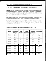
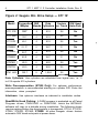
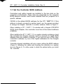
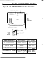
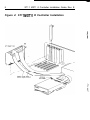
ST11M, ST11R
ST412 Interface Controller
lnstalla tion Guide
#Seagate
Copyright Notice
S e a g a t e , Seagate Technology and the Seagate logo are registered
trademarks of Seagate Technology, Inc. l N S T A L L R is a trademark of
Seagate Technology, Inc.
©Copyright 1990 Seagate Technology, Inc.
920 Disc Drive, Scotts Valley, California 95066-4544, USA
Telephone: 408/438-6550
Publication Number: 36095-001, Rev. E
Seagate reserves the right to change, without notice, product offerings
or specifications. This publication, and all material contained herein, are
copyrighted with all rights reserved. No part of this publication may be
copied without written permission of Seagate Technology, Inc.
PC/Al@ and PC-DOS@ are registered trademarks of International Business Corporation. X T is a trademark of International Business
Machines Corporation.
DISK MANAGER@ is a registered trademark of ONTRACK Computer
Systems, Inc.
MS-DOS® is a registered trademark of Microsoft Corporation.
ST1 1 M/ST11 R Controller Installation Guide, Rev. E
1
Introduction
This installation guide supports the Seagate ST1 1M MFM and
ST1 1 R RLL Controllers, ROM Version 2.0 or higher.
The ST1 1 M and ST1 1 R are 8-bit ST41 2 interface controllers designed
for use in PC XT/AT systems with DOS-based applications. Use with
other than DOS-based systems is beyond the scope of this guide.
Contact your Distributor/Dealer.
.
.
.
The ST1 1 M is designed for use with drives employing MFM data
encoding.
The ST1 1 R is designed for drives using RLL (2,7) data encoding.
Seagate RLL drives are easily recognized by an R after the model
number, e.g., ST157R. Seagate Technology, Inc. assumes no
liability for installation of an RLL controller with an MFM-certified
drive.
The ST1 1 M/ST1 1 R have a unique recording format and therefore
require all attached drives to be installed by one of the processes
described in this guide before operation.
This guide may be used with Seagate Paired Program drives or
as a controller-only installation guide.
Paired Program drives are shipped with a Seagate controller. They are
recognized by a PR label on the drive top cover. Paired drives are
shipped formatted with a small DOS partition containing the installation
program, INSTALLR, which will low-level format and partition your drive.
You must supply the DOS program. The ST1 1 M/ST1 1 R can recognize
whether a drive has the Paired Program software loaded, or has been
previously installed.
Paired Program drives with formatted capacities greater than 32 MBytes
have DISK MANAGER partitioning software loaded. This utility has been
customized by ONTRACK for Seagate. Refer to Section 2.1 for special
instructions on formatting Paired Program drives.
2
ST1 1 M/ST1 1 R Controller Installation Guide, Rev. E
Before You Begin...
Inspect the controller, drive, cables, mounting hardware/accessories,
documentation and packaging. If any item is incorrect, missing or appears damaged, contact your Distributor or Dealer immediately.
Handling: Improper handling during transit/shipping accounts for many
“installation” problems. Prior to installation, handle your drive/controller
carefully.
Observe Static-Discharge Precautions: Keep the drive/controller in
their static-shielded bags until you are ready to complete the installation.
Use a grounded wrist-strap at your workstation; if unavailable, ground
yourself frequently by touching the metal chassis of the system before
handling any components. Avoid static-inducing carpeted areas.
Shipping: When transporting or shipping a drive or controller, a
Seagate-approved container must be used. Keep your original box. They
are easily identified by a red label identifying them as a Seagate
Approved Package.
Shipping a drive in a non-approved container will void the drive
warranty.
Repair centers may refuse receipt of components improperly packaged
or obviously damaged in transit. Contact your Distributor to purchase
additional boxes. Seagate recommends shipping by an air-ride carrier
experienced in handling computer equipment
Maintenance: Seagate disc drives do not require any preventative
maintenance. The head/disc assembly is sealed and does not contain
any user-serviceable components. Tampering with the factory-seal will
void the warranty.
Warranty: The terms of your warranty are determined by your authorized
Seagate Distributor or Dealer. Warranties do not extend to data stored
on drives.
ST1 1 M/ST1 1 R Controller Installation Guide, Rev. E
1 .O ST1 1 M/ST1 1 R Controller Installation
Caution: Do not handle a drive or controller without observing static-discharge precautions. A grounded wrist-strap is preferred; if unavailable,
ground yourself frequently by touching the metal chassis of the system
before handling any components. Do not unpack the drive/controller until
you are ready to complete the installation.
BEFORE ATTEMPTING ANY INSTALLATION, READ THROUGH ALL
STEPS AND VERIFY THAT THE SYSTEM IS POWERED-DOWN.
During the formatting process, you will be asked to enter some simple
drive specifications. Please refer to Figures l-2 for formatted capacity
and basic specifications. For non-Seagate drives, refer to the
manufacturer’s instructions.
Figure 1: Seagate MFM Drive Setup - ST1 1 M
ST225 1
21.4
4
615
17
No
ST252
42.8
6
820
17
Yes
ST25 1
42.8
6
820
17
Yes
ST4053
44.5
5
1,024
17
Yes
ST4096
80.2
9
1,024
17
Yes
4
ST1 1 M/ST1 1 R Controller Installation Guide, Rev. E
Figure 2: Seagate RLL Drive Setup - ST1 1R
T
Model
7
Formatted R/W
Data
Sectors R/W Head
MBytes
Heads Cylinders per Track Auto-Park
4
ST1 37R
32.7
4
615
26
No
ST1 38R
32.7
4
615
26
Yes
49.1
6
615
26
Yes
21.17
2
667
31
No
32.7
4
615
26
No
42.9
4
667
31
No
65.5
6
820
26
Yes
65.5
6
820
26
Yes
122.7
9
ST1 57R
c
ST225R
L
ST238R
+
ST250R
ST278R
ST277R
ST41 44R
t
-I-
i
I
1,024
26
-___
Yes
Data Cylinders: User cylinders are calculated from logical zero, i.e., 0
to 614 equals 615 cylinders.
Write Precompensation (ST225 Only): For optimum performance,
precompensation is recommended starting on cylinder 300. Enter the
information, when prompted.
Interleave: Use optimum interleave as indicated in installation routine
Read/Write Head Parking: A PARK program is preloaded on all Paired
Program drives, PARK.EXE or PARK.COM, which the INSTALLR
software will copy to a diskette during installation. The following drives
require parking before the drive/system is transported: ST124, ST137R,
ST225, ST225R, ST238R, ST250R. All other Seagate drives feature
automatic R/W head auto-park at power-down.
ST1 1 M/ST1 1 R Controller Installation Guide, Rev. E
5
1.1 Set the Controller BIOS Address
Controllers and add-in boards are installed in the bus slots on the
computer’s motherboard. These slots are recognized by the computer
BIOS address number. Each board installed must be jumpered for a
specific address.
C8000H is the default BIOS address for the ST1 1M/ST11 R. If this
address is already occupied by another board, use the jumpers provided
to change the Seagate controller to another address. Refer to Figure 3.
When installing a ST1 1 M/ST1 1 R controller with a Seagate ST01/ST02
SCSI Host Adapter, the controller must be at the lowest address
(C8000H).
When installing the ST1 1 M/ST1 1 R in a system already containing a hard
disc controller, the Seagate controller must be jumpered at a higher BIOS
address than the resident controller. If you are not sure of the other
controller’s address, try one of the higher addresses for the Seagate
controller.
Controller physical installation will only involve setting the BIOS address
(Figure 3), attaching the cables and inserting the controller in a system
bus slot (Figure 4). It is often easier to attach the cables before you install
the controller.
6
ST1 1 M/ST1 1 R Controller Installation Guide, Rev. E
Figure 3: ST1 1M/ST11R ST412 Interface Controller
J2 Drive 1 J3
-
Drive 2
Jl
2s
-
ADDRESS
SELECTION
J5 AUX. DRIVE POWER
PIN
1
2 +12VDC
4 NOT USED
+12VDC 1
6 GROUND
+5VDC 3
GROUND 5
I
I
I
I
Jumper Setting at WI
BIOS Address
No Jumpers Installed
C8000H (Default)
320H - 323H
Pins A-B Shorted
DOOOOH
324H - 327H
Pins C-D Shorted
D8000H
328H -
’ Pins A-B and C-D Shorted EOOOOH (Do not use
on AT-class system)
’ Port Address
32BH
32C~ -
32F~
1
I
ST1 1 M/ST1 1 R Controller Installation Guide, Rev. E
7
1.2 Controller Physical Installation
CAUTION: VERIFY THAT THE POWER IS OFF.
1.
Remove the System Cover (Refer to your system manual).
Access to the screws is usually at the back of the system. Save the
screws. Systems vary, but most require you to slide the cover foward
for removal.
2. Install the Controller as Illustrated in Figure 4.
Verify that all connections are correct and replace the system cover
3. Optional Drive Power Connector on the ST1 1 M/ST1 1 R
Normally, drive power is supplied via a power harness from the
system power supply directly to the drive’s J3 DC power connector.
The J5 connector on the ST1 1 M/ST1 1 R can be used to provide disc
drive power in systems lacking an extra power harness or for
Drive-on-a-Cardapplications. See connector J5, Figure 3.
A cable splitter, often called a Y-cable, may be used to tap off the
diskette drive power cable. They are available from most Distributors/Dealers.
8
ST1 1 M/ST1 1 R Controller Installation Guide, Rev. E
Figure 4: ST1 IMET R Controller Installation
Cables usually have a
colored stripe for Pin-1
ST1 1 M/ST1 1 R Controller Installation Guide, Rev. E
9
2.0 Preparing to Format Your Drive
Please read this section before proceeding to the formatting instructions. Be sure to back up any drive containing data. Formatting
at any level may result in partial or complete loss of data. Seagate
Technology, Inc. assumes no liability for lost data.
.
Always use the same version of DOS throughout the entire process.
On two-drive systems: Always use the same version of DOS on both
drives. When adding a second drive, it is sometimes necessary to
reformat the first drive.
.
DOS assigns a logical identifier (C, D, E . ..) to each partition that it
recognizes during the boot load. It assigns these letters to the first
partition on each physical drive in sequential order (e.g., C to Drive
1, D to Drive 2. Subsequent letters are assigned to the remaining
partitions on Drive 1, followed by Drive 2. See table below for typical
examples:
.
For optimum performance, format the drive installed in your system
in the same orientation in which it will be used.
2.1 Paired Program Drive Formatting
Paired Program drives are shipped with a small DOS partition containing
Installation software and a README file which has the latest information
for the drive being installed. See Section 3.0.
10
ST1 1 M/ST1 1 R Controller Installation Guide, Rev. E
2.2 Non-Paired Drive formatting
Seagate non-paired drives do not have installation software or recognizable format. These drives may be installed by following the procedures in Section 4.0.
2.3 Paired Drives with Less than 32 Formatted MBytes
You will need one DOS-bootable diskette that has the boot files from the
version of DOS that you plan to use on your Seagate drive. This diskette
should also contain the FORMAT program provided with DOS, and
sufficient space (approximately 50 KBytes) to save the installation
programs from the hard drive. The diskette must not be write-protected.
2.4 Paired Drives with Greater than 32 Formatted MBytes
You will need two diskettes; one DOS-bootable with the version of DOS
you plan to use. The second diskette must have at least 360K Bytes
available to save the installation and DISK MANAGER programs. The
diskettes must not be write-protected.
2.5 CMOS Configuration
If you are installing your drive in a PC/AT and a hard drive is not presently
attached or operational, the hard drive count in CMOS will already be
set to zero.
If a standard hard drive is already attached and operating, it will be the
first drive and the Seagate Paired Program drive will be Drive 2. It is not
necessary to change the CMOS hard drive count when installing with
ST1 1 M/ST1 1 R controllers.
2.6 Read/Write Head Parking
A PARK program is preloaded on all Paired Program drives. The
following drives require this program before the drive/system is
transported: ST124, ST137R, ST225 ST225R, ST238R, ST250R. All
other Seagate drives feature automatic head parking at power-down.
ST1 1 M/ST1 1 R Controller Installation Guide, Rev. E
11
3.0 Paired Program Installations
Read Sections 1-2 before beginning any formatting. The entire
software installation routine is menu-driven and takes from ten to thirty
minutes, depending on drive size. For specific DOS questions, refer to
the DOS manual supplied with your system. After the format is completed, the read/write heads will be parked. At the next power-up, the
system will boot from the hard disc.
3.1 Paired Program Formatting
Place a DOS-bootable diskette (to boot simply means to start the system)
in Drive A and switch the power on and follow the instructions displayed
on the screen. If you are installing a second drive, type:
D:INSTALLR D
If you are installing a drive with DISK MANAGER software, and you
already have a hard disc in your system, you must copy the
DMDRVR.BIN and CONFIGSYS files from the DISK MANAGER diskette to the existing (first, or boot) drive.
If you already have a CONFIGSYS file on the boot drive, update the file
to include the following line: DEVICE=DMDRVR.BIN.
Refer to your DOS manual for instructions on editing the CONFIGSYS
file. DISK MANGER also provides help files which you may print using
the standard DOS print commands.
12
ST1 1 M/ST1 1 R Controller Installation Guide, Rev. E
4.0 Non-Paired Drive Formatting
Use this procedure for non-paired drives or when reformatting a paired
drive whose installation software files were lost or not copied before
formatting.
Be sure to back up any drive containing data. Formatting at any level
may result in partial or complete loss of data. Seagate Technology, Inc.
assumes no liability for lost data.
If you use the DOS DEBUG utility to low-level/primary format the drive,
you must answer “YES” to the question, “Do you want to enter the defect
map which is supplied on your hard disc drive cover”. Proceed with
entering all defects from the defect map.
Important Note: If you use the ST1 1 M/ST1 1 R controller, BIOS Version
2.0, with a Seagate Paired Program drive, but do not use the Seagate
installation software (INSTALLR), you must manually enter the
Manufacturer’s Defect Map (attached to the drive top cover) during the
low-level/primary formatting operation.
Always use the same version of DOS throughout the entire process. On
two-drive systems: Always use the same version of DOS on both drives.
When adding a second drive, it is sometimes necessary to reformat the
first drive.
4.1 Low-Level Physical Format Using BIOS Facility
When using DEBUG to format in a AT system, the CMOS or system
setup should be set to 0 (i.e., no hard drive installed).
1.
Boot the system from the DOS system diskette
2.
At the A: prompt, insert the DEBUG diskette and type:
DEBUG
<ENTER>
ST1 1 M/ST1 1 R Controller Installation Guide, Rev. E
3.
13
To access the controller’s format routine; at the “-” prompt type:
G=XXXX:5 (Where XXXX is correct address, Refer to Fig 3.)
Note: Seagate controllers will step you through the process. Refer
to the drive charts Figures l-2 for correct drive parameters.
On drives over than 32 formatted megabytes, DISK MANAGER will
automatically partition and high-level format the drive.
Use FDISK and FORMAT on your DOS diskette for drives less than
32 formatted megabytes.
5.0 Troubleshooting Your Installation
If you have a problem getting the initial screen, or later getting the system
to boot:
l
l
Check the cabling between the controller and drive. Pin-l on the
controller always corresponds to Pin-l at the drive connector. Most
cables have a contrasting color on the cable to indicate Pin-l.
Check the power cable to the drive. Can you hear the drive spinning
up?
.
Verify correct Drive Select number.
.
Verify correct BIOS address for the controller. See page 6. If you
have more than one board that uses BIOS ROM space, each must
be configured to a different memory address. Addressing multiple
boards at the same memory location can cause problems of a
seemingly indeterminate nature.
.
Low-level formatting takes too long or never completes.
Format again. Make sure correct drive parameters were entered and
cable connections are correct.
.
FDISK or Partitioning Error Messages: “Error reading fixed disc” “No
fixed disc present”
14
ST1 1 M/ST1 1 R Controller Installation Guide, Rev. E
Check correct drive parameters entered. Refer to pages 3-4. Turn
the system off and power-up again. Rerun FDISK.
.
High-Level Format Error Message: “Invalid drive specification”
Run FDISK again to make sure the DOS partition is active. Check
drive parameters and low-level format again. Check controller
jumpers.
In AT systems, check that no drive type is entered in the system
CMOS setup for the drive attached to the ST1 1 M/ST1 1 R.
.
Drive fails to recalibrate or test Ready.
Check installation, cables and drive select jumper.
.
I/O error messages when using DISK MANAGER:
“Uncorrectable ECC - I/O Error”
“Unrecoverable I/O Error”
If you are formatting a drive in an XT or using the ST1 1 M/ST1 1 R
controller in an AT, low-level format the drive through DEBUG using
the controller’s BIOS routine.
.
After formatting with DISK MANAGER, your system does not recognize the D, E, F... partitions:
First, make sure that you boot from the hard drive. If you still cannot
access these partitions, check that the DISK MANAGER device
driver, DMDRVR.BIN is in the root directory of the C: (boot) drive.
Verify that the CONFIG.SYS file contains the following line:
DEVICE = DMDRVR.BIN
If you experience problems accessing your DOS partition after installation, refer to the help files provided with DISK MANAGER.
For system or DOS help, contact your computer system manufacturer.
For additional installation help, contact your authorized Seagate Distributor/Dealer.