1
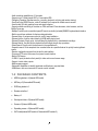
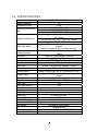
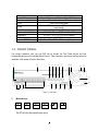
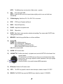
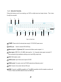
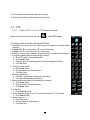
Instruction Manual
PARAGON264x4-32CH Series
DVR
EVERFOCUS ELECTRONICS CORPORATION
PARAGON264x4-32CH Series DVR
Instruction Manual
2011 EverFocus Electronics Corp
www.everfocus.com
All rights reserved. No part of the contents of this manual may be reproduced or transmitted in any form or by
any means without written permission of the Everfocus Electronics Corporation.
Release Date: June 2011
QuickTime is a registered trademark of the Apple Computer, Inc.
Windows is a registered trademark of the Microsoft Corporation.
Linksys is a registered trademark of the Linksys Corporation.
D-Link is a registered trademark of the D-Link Corporation.
DynDNS is a registered trademark of the DynDNS.org Corporation.
Other product and company names mentioned herein may be the trademarks of their respective owners.
Safety Precautions
• To avoid any damage, please consider the following safety warnings:
• Never place the recorder near to heaters, furnaces, other heat sources or under direct solar irradiation.
• Operate the device only in locations providing the tolerable operating temperature range
0°C~40°C/32°F ~ +104°F.
• Make sure that the device‘s ventilation slots are not covered or sheeted.
• For cleaning, make sure the device is plugged off and only use a damp cloth without acid detergent.
• Install the device only in dry and dustproof surroundings. Protect the device against any liquid‘s
penetration.
• Avoid the penetration of any artifacts, e.g. through ventilation slots.
• Do not attempt to disassemble the appliance. To prevent electric shock, do not remove screws or
covers. There are no user-serviceable parts inside. Contact qualified service personnel for maintenance.
Handle the appliance with care. Do not strike or shake, as this may damage the appliance.
• Do not operate appliance with other than specified power supplies. The input power source of the power
supply is 100 ~ 240 VAC.
• Avoid any affection of the device through vibrations or mechanical shock at the recorder‘s installation
location.
• Avoid to power off DVR during playback or recording operation.
"Rack Mount Instructions - The following or similar rack-mount instructions are included with the installation
instructions:
A) Elevated Operating Ambient - If installed in a closed or multi-unit rack assembly, the operating ambient
temperature of the rack environment may be greater than room ambient. Therefore, consideration should
be given to installing the equipment in an environment compatible with the maximum ambient temperature
(Tma) specified by the manufacturer.
B) Reduced Air Flow - Installation of the equipment in a rack should be such that the amount of air flow
required for safe operation of the equipment is not compromised.
C) Mechanical Loading - Mounting of the equipment in the rack should be such that a hazardous condition
is not achieved due to uneven mechanical loading.
D) Circuit Overloading - Consideration should be given to the connection of the equipment to the supply
circuit and the effect that overloading of the circuits might have on overcurrent protection and supply wiring.
Appropriate consideration of equipment nameplate ratings should be used when addressing this concern.
E) Reliable Earthing - Reliable earthing of rack-mounted equipment should be maintained. Particular
attention should be given to supply connections other than direct connections to the branch circuit (e.g. use
of power strips)."
ii
ATTENTION! This is a class A product which may cause radio interference in a domestic environment; in
this case, the user may be urged to take adequate measures.
Federal Communication Commission Interference Statement
This equipment has been tested and found to comply with the limits for a Class B digital device, pursuant to
Part 15 of the FCC Rules. These limits are designed to provide reasonable protection against harmful
interference in a residential installation. This equipment generates, uses and can radiate radio frequency
energy and, if not installed and used in accordance with the instructions, may cause harmful interference to
radio communications. However, there is no guarantee that interference will not occur in a particular
installation. If this equipment does cause harmful interference to radio or television reception, which can be
determined by turning the equipment off and on, the user is encouraged to try to correct the interference by
one of the following measures :
•Reorient or relocate the receiving antenna.
•Increase the separation between the equipment and receiver.
•Connect the equipment into an outlet on a circuit different from that to which the receiver is connected.
•Consult the dealer or an experienced radio/TV technician for help.
FCC Caution: Any changes or modifications not expressly approved by the party responsible for compliance
could void the users’ authority to operate this equipment.
WEEE
This Product is RoHS compliant.
The information in this manual was current upon publication. The manufacturer reserves the right to revise and improve his products.
Therefore, all specifications are subject to change without prior notice. Misprints reserved.
Please read this manual carefully before installing and using this unit. Be sure to keep it handy for later reference.
iii
TABLE OF CONTENTS
1
PRODUCT OVERVIEW ..................................................................................................... 1
1.1
1.2
1.3
1.4
1.5
1.6
1.7
1.8
FEATURES ....................................................................................................................... 1
PACKAGE CONTENTS................................................................................................... 2
SPECIFICATIONS ........................................................................................................... 4
FRONT PANEL ................................................................................................................ 5
REAR PANEL................................................................................................................... 8
MONITOR INSTALLATION......................................................................................... 10
AUDIO INSTALLATION .............................................................................................. 11
ALARM CONTACTS INSTALLATION ....................................................................... 11
1.8.1
1.8.2
1.9
Alarm Input Contacts ............................................................................................................................11
Alarm Output Relay...............................................................................................................................11
RS-485 KEYBOARD / PTZ INSTALLATION ......................................................................... 12
1.9.1
1.9.2
1.9.3
1.9.4
1.9.5
General RS-485 bus installation ...........................................................................................................12
RS-485 socket pin assignment ...............................................................................................................13
EKB-500 connection with network patch cable.....................................................................................14
EKB-500 connection to several DVRs...................................................................................................14
Speed Dome Installation .......................................................................................................................14
1.10
1.11
USB-MOUSE INSTALLATION .......................................................................................... 14
NETWORK CONNECTION........................................................................................ 14
1.11.1
1.11.2
1.12
2
Direct PC Connection through Crossover Network Cable ...................................................................15
Network Connection through Patch Cable............................................................................................15
FINAL INSTALL PROCESS ....................................................................................... 16
MOUSE AND FRONT PANEL OPERATION ............................................................... 17
2.1
GENERAL USB MOUSE OPERATION ....................................................................... 17
2.1.1
2.1.2
2.1.3
2.1.4
2.2
GENERAL FRONT PANEL OPERATION ............................................................................... 20
2.2.1
2.2.2
2.2.3
2.2.4
2.2.5
3.
3.1
3.2
3.3
3.4
3.5
How to select a channel / Enable audio ................................................................................................17
OSD Root Menu.....................................................................................................................................17
Operation in the Configuration Menus .................................................................................................18
Field Input Options ...............................................................................................................................18
How to select a channel / Enable audio ................................................................................................20
OSD Root Menu.....................................................................................................................................20
Front Panel Key Review........................................................................................................................20
Operation in Configuration Menu.........................................................................................................20
Field Input Options ...............................................................................................................................21
GENERAL DVR OPERATIONS...................................................................................... 23
RECORD ............................................................................................................................ 23
LOGIN ............................................................................................................................... 23
SELECT CAMERA OPERATION................................................................................. 24
CHANGE AUDIO OUTPUT OPERATION................................................................... 24
PLAYBACK.................................................................................................................... 24
iv
3.6
PTZ .................................................................................................................................. 26
3.6.1 General PTZ control (if PTZ cameras are installed)......................................................................................26
3.6.2 Express Control of PTZ.............................................................................................................................27
3.7 LAYOUT ............................................................................................................................ 29
3.7.1
Bring a camera to full screen mode.......................................................................................................29
3.8 CHANNEL SWITCHING............................................................................................... 29
3.9 DISPLAY ........................................................................................................................ 30
3.10
SEQUENCE.................................................................................................................. 30
3.11
ZOOM........................................................................................................................... 30
3.12
SEARCH....................................................................................................................... 32
3.12.1
3.12.2
3.12.3
3.12.4
3.13
3.14
4
Time Search...........................................................................................................................................32
Event Search..........................................................................................................................................33
Smart Search .........................................................................................................................................34
Snapshot Search ....................................................................................................................................36
COPY............................................................................................................................ 37
LOGOUT ...................................................................................................................... 38
DVR CONFIGURATION .................................................................................................. 39
4.1
4.2
4.3
4.3.1
4.3.2
4.3.3
4.3.4
4.4
4.4.1
4.4.2
4.4.3
4.5
4.5.1
4.5.2
4.6
4.6.1
4.6.2
4.6.3
4.6.4
4.7
4.7.1
4.7.2
4.7.3
4.7.4
4.7.5
4.8
4.8.1
4.8.2
4.9
4.9.1
4.9.2
CONFIGURATION MENU............................................................................................ 39
EXPRESS ........................................................................................................................ 39
CAMERA SETTING ...................................................................................................... 42
Basic Setting..........................................................................................................................................42
Video Adjust ..........................................................................................................................................45
Motion ...................................................................................................................................................46
Video Loss .............................................................................................................................................49
RECORD & PLAY SETTING........................................................................................ 50
Record ...................................................................................................................................................51
Built-in Calculator ................................................................................................................................52
Play .......................................................................................................................................................53
ALARM & EVENT SETTING....................................................................................... 54
Alarm.....................................................................................................................................................54
Event......................................................................................................................................................56
SCHEDULE SETTING................................................................................................... 64
Express Setup .......................................................................................................................................64
Holidays ................................................................................................................................................65
Schedule ................................................................................................................................................66
Alarm Action .........................................................................................................................................72
NETWORK SETTING.................................................................................................... 76
LAN .......................................................................................................................................................76
EMAIL ...................................................................................................................................................78
DDNS ....................................................................................................................................................79
Alarm Server .........................................................................................................................................81
Network Test..........................................................................................................................................82
DISK INFORMATION ................................................................................................... 83
Disk .......................................................................................................................................................83
Lock/Format ..........................................................................................................................................84
DISPLAY SETTING....................................................................................................... 85
Monitor OSD .........................................................................................................................................85
Main M/T SEQ ......................................................................................................................................86
v
4.9.3
4.9.4
Call M/T SEQ ........................................................................................................................................87
Matrix Seq. ............................................................................................................................................88
4.10
SYSTEM SETTING ..................................................................................................... 89
4.10.1
4.10.2
4.10.3
4.10.4
4.10.5
4.10.6
4.11
INFORMATION........................................................................................................... 97
4.11.1
4.11.2
5
Date/Time ..............................................................................................................................................89
Daylight Saving .....................................................................................................................................90
User .......................................................................................................................................................91
I/O Control ............................................................................................................................................94
Misc. ......................................................................................................................................................95
Quick Archive........................................................................................................................................96
System....................................................................................................................................................97
Log.........................................................................................................................................................98
NETWORKING OVERVIEW ........................................................................................ 100
5.1
5.2
5.3
5.4
5.5
5.6
5.7
5.8
5.9
6
INTRODUCTION TO TCP/IP ............................................................................................. 100
SUBNET MASKS .............................................................................................................. 100
GATEWAY ADDRESS ....................................................................................................... 100
VIRTUAL PORTS.............................................................................................................. 101
PRE-INSTALLATION ........................................................................................................ 101
WHAT IS YOUR NETWORK SETUP?.................................................................................. 102
SIMPLE ONE TO ONE CONNECTION ................................................................................. 103
DIRECT HIGH SPEED MODEM CONNECTION ................................................................... 108
ROUTER OR LAN CONNECTION ...................................................................................... 110
REMOTE OPERATION FROM BROWSER............................................................... 113
6.1
6.2
CONNECTING TO PARAGON 264X4....................................................................... 113
BROWSER SECURITY SETTING .................................................................................. 114
6.2.1
6.2.2
6.3
6.4
Installing ActiveX controls ..................................................................................................................114
Enabling ActiveX Controls ..................................................................................................................117
REMOTE LIVE VIEW ................................................................................................. 120
REMOTE PLAYBACK ................................................................................................ 122
7
EVERFOCUS DDNS SETUP .......................................................................................... 123
8
LINKSYS & D-LINK PORT FORWARDING ............................................................. 125
8.1
8.2
9
TYPICAL LINKSYS PORT FORWARDING ............................................................. 125
TYPICAL D-LINK PORT FORWARDING ................................................................ 127
TROUBLESHOOTING ................................................................................................... 130
APPENDIX A: TIMING OF ALARM MODES.................................................................... 131
APPENDIX B: CHANGING RULE FOR EXPRESS SETUP ............................................. 134
vi
Chapter
1
1 PRODUCT OVERVIEW
The introduction of the PARAGON264X4 32CH DVR adds the advantages of H.264 compression to the
power and flexibility of the already popular PARAGON DVR. State of the art H.264 compression
techniques enhance recorded video storage capacity and conserve network transmission bandwidth while
maintaining high image quality. This powerful DVR is capable of real time recording at Half D1 resolution on
all 32 channels. “Plus, the ability to independently configure image resolution and frame rate for individual
cameras allows some cameras to be recorded at 4CIFwhile others are set at CIF or 2CIF to optimize the
recording parameters for each application.” Viewing live or recorded video, the full HD 1080p display
proves superior clarity on a massive scale, allocating two megapixels of resolution to the main monitor
display. HDMI digital output renders stunning images from any source, and enhances motion reproduction
to deliver smoother and crisper looking video.
The new enhanced color Graphical User Interface (GUI) makes configuration over the network, from the
front panel or with the included mouse fast and easy. An Express Setup option allows rapid configuration of
time & date, global recording settings and network configuration from a single screen. Choose from
continuous, event or schedule recording, or pick the number of days you want to record and the Express
Setup does the rest. View live, play back recorded video and configure the DVR remotely over a LAN or
WAN with the included web browser interface; check your home or business on the go from a cell phone or
PDA – the PARAGON264 supports multiple remote access methods.
On playback, in addition to traditional date/time and event searches PARAGON DVR also provides
powerful Smart and Snapshot Search functions. Review recorded video and let the DVR identify motion in
area(s) of interest during playback, or choose a starting date/time, an interval and direction and view a
series of snapshots extracted from recorded video to quickly isolate and play back relevant video for
efficient review of significant activities.
1.1 FEATURES
- 2CIF real time recording rate for all cameras
- HDMI video output (1080p) plus VGA 1280x1024
-Simultaneous main streaming (400 PAL/480 NTSC (4CIF)) for remote viewing
-H.264 Compression format for efficient disk utilization and network bandwidth conservation
-Normal and event recording frame rate can be set independently for each camera
-Recording resolution can be changed at different times of the day via schedule
-Supports eSATA
-Gigabit Ethernet interface for remote network viewing and control
1
-Audio recording capabilities on 16 channels
-Supports up to 4 fixed internal HDD or 2 removable HDD
-Pentaplex Operation (Simultaneous live, recording, playback, archiving and remote viewing)
-Free EverFocus DDNS Service - static IP address is not required for reliable remote access
-User friendly GUI with graphical icons and visual indicators
-Supports mobile monitoring of live video on PDA and Smart Phone browsers, other browsers, and via
Mobile Focus app
-Multiple Control Inputs: mouse/front panel/IR remote controller (included)/EKB500 keyboard/web interface
-Built-in record time calculator for fast recording estimation
-Express Setup: A unique menu option for quick & easy installation
-Express Archive: Archive video instantly (to USB) while playing back
-Express Playback: Simply point, click and drag the playback bar to view desired recordings
-Express Search: Use the intuitive playback bar with simple drag & drop operations
-Smart Search: Directly catch the movement in the specified area
-Snapshot search: Show snapshots from recorded video at a specified interval to quickly locate significant
events
-Remote configuration support from the built-in web interface
-On-screen PTZ control via mouse, front panel or web interface
-Built-in DVD burner
-2 USB 2.0 ports (located on front panel) for video archive and mouse usage
-Support 4 matrix video outputs
-Multi-language support
-Watermark capabilities to identify intentional modifications to exported data
-USB Mouse, rack mount ears and IR remote control included
1.2 PACKAGE CONTENTS
HDD fixing bracket x 4 (Internal HDD model)
HDD tray x 2 (Removable HDD model)
DVR fixing bracket x 2
Remote controller x 1
Battery x 2
Shockproof rubber x 16(Internal HDD model)
Screws x 16(Internal HDD model)
Expanding screws x 16(Internal HDD model)
SATA cable(Internal HDD model x4, Removable HDD model x 2)
2
Power cord x 1
Mouse x 1
DVR x 1
User manual x 1
3
1.3 SPECIFICATIONS
PARAGON264X4 32CH
Number of Channels
32
Compression Format
H.264
480 NTSC /400 PAL (4CIF)
Recording Rate/Resolution
960 NTSC /800 PAL (2CIF)
(Max)
960 NTSC /800 PAL (CIF)
480 NTSC /400 PAL (4CIF) --16CH, 4CIF 15 NTSC/12.5 PAL
per Channel
Playback Rate/Resolution
480 NTSC /400 PAL (2CIF) ---16CH, 2CIF real-time
480 NTSC /400 PAL (CIF)---16CH, CIF real-time
Live view on PDA or smart phone browsers, plus various web
browsers
Mobile View Support
Mobile Focus apps for iPhone, Android and others
Simultaneous Live, Recording, Playback, Archive and Remote
Pentaplex Operation
Viewing
Video Inputs
32 BNC (NTSC/PAL automatic selection)
Main Monitor Outputs
HDMI/VGA (1080p)
Call Monitor Output
BNC (NTSC/PAL; follows input type)
Video Matrix Monitor Output
BNC x 4
Audio Inputs
16 inputs: 16 on RCA socket (supplied); Line level
Audio Outputs
2 x RCA socket; Line level
Recording Modes
Manual, Schedule and Event; or, choose Number of Days
Date/Time, Event, Motion in Recorded Video, snapshot by
Playback Search
Interval
Alarm Inputs
16 inputs
Alarm Out
4 form “C” (SPDT) relays; 30VDC@1A rating
Video Pause
Yes
Video Loss Detection
Yes
Motion Detection
Yes
Event Log
Yes
Watch Dog Timer
Yes
Internal HDD
4 Internal SATA HDD
External HDD
1 eSATA
Built-in DVD Burner
Slim Type DVD Burner
Hot-swappable HDD
2 (optional)
User Interface
GUI(Graphical User Interface)
OS
Embedded Linux
Network/Protocol
Gigabit Ethernet; TCP-IP / DHCP/ PPPoE / DDNS
Control PTZ via OSD
Yes (via both local and remote interfaces)
4
USB
Schedule Setting
User Access
RS-232
2 USB 2.0 port (on Front Panel)
Supports Express and Advanced Schedule Setting
3 Levels of User Access Defined
9-pin D-Sub socket (male)
RJ45x2 for DVR control input and PTZ control output; data
loops through
100~240VAC ,110W max
430 x 423 x 72 mm / 16.93" x 16.65" x 3.13"
0°C~40°C / 32°F~104°F (20~80% humidity)
CE, FCC, UL
EverFocus, Pelco D, Pelco P, Samsung, Transparent
RS-485
Power Source
Dimensions (L x W x H)
Temperature
Certificates
Supported PTZ Protocols
1.4 FRONT PANEL
Your primary interaction with your new DVR will be through the Front Panel buttons and their
corresponding buttons on the included Remote Control. Take a moment to learn where the keys are as the
remainder of the manual will refer to them often.
1
2
3
4
5
6
7
8
9
10
11
12
13
22
20
21
19
18
17
16
Figure 1-1 Front Panel
1)
Multiview Keys:
4
8
16
32
4x
9x
16x
32x
6/8/13x
The LED will show the selected screen layout.
5
10x
15
14
NOTE:
The Multiview keys are only active in Main monitor - operation.
2)
HDD:
Removable SATA HDD.
NOTE: To open the HDD cover at front panel, please slightly push the cover, and it will open
automatically.
3)
CH Switching key: Switch from CH1~16 to CH17~32 or vice versa.
4)
STOP:
STOP key for Playback and Record
5)
BACK:
Reverse Playback key
6)
PAUSE: Image freeze in playback mode
7)
PLAY:
8)
ENTER: Enter Key for menu operation and alarm acknowledge Turn camera audio ON/OFF when
viewing full screen camera.
9)
MENU/ESC: Used to bring up Main Menu or exit from sub-Menus.
10)
System LED
POWER: LED indicating power on.
HDD1/2: LED indicating HDD1 / HDD2 active
HDD1: Internal/Removable HDDs in DVR
HDD2: External HDDs connected by eSATA port
LAN: LED for network traffic
11)
ALARM: LED for alarm status
12)
JOG/SHUTTLE: Shuttle (outer wheel): In playback mode, use the SHUTTLE for fast forward / fast
reverse playback.
JOG (inner wheel): In PAUSE mode, use the jog to move frame by frame. Within
menu functions, use the jog to adjust the values / parameters. Use Jog to highlight
individual cameras.
Use either Shuttle or Jog to switch between MENU parameters.
Jog
Shuttle
Playback key
13)
IR Receiver: Receiver for IR remote control
14)
COPY:
15)
SEARCH: The SEARCH key opens the SEARCH menu, details in chapter 3.12 SEARCH.
The COPY key opens the menu for video data export, details in chapter 3.13 COPY.
6
16)
MONITOR: The MONITOR key switches operation between MAIN and CALL. The active screen will
be Main monitor when LED is in “M” and Call monitor when LED is in “1”.
17)
ZOOM: 2x electronical zoom.
For details please consult chapter 3.11 ZOOM.
NOTE: The Zoom key is only active in Full screen at Main monitor.
18)
SEQ:
19)
DISPLAY: The DISPLAY key switches titles and status messages on the Screen in 4 steps. For
details please consult chapter 3.9 DISPLAY.
20)
Channel keys: 1~16 / 17~32 for full screen display of selected channel. The LED will show the
active channel.
21)
DVD+RW Burner: DVD+RW drive for video data export.
22)
2 x USB-2.0 port for USB mouse, USB-Flash-Drive
Sequence key for automatic switching of a defined camera sequence
7
1.5 REAR PANEL
During initial setup you will be connecting your DVR to multiple input and output devices. This is done
through the rear panel.
1
2
4
3
14
5
6
7
8
9
10
11
12
13
Figure 1-2 Rear Panel
1
POWER: Power socket for external power supply, 100~240VAC power source
2
eSATA port:
3
Matrix outputs 1~4 (Optional): BNC connectors for Matrix monitor outputs 1~4.
4
Used for external SATA HDD bay
Video inputs: VIDEO IN (1~32): BNC video inputs for 1 Vpp Composite video signals, automatic 75
Ohm termination (high impedance switching upon loop-through output load)
5
LAN: RJ45 network socket
6
RS232 socket: 9-pin D-Sub control input for RS-232
7
RS485 socket: For remote control via RS-485 keyboards and telemetry control
8
VGA: Connect to the monitor that has VGA input.
9
HDMI: Connect to an HDMI-compatible unit. This HDMI-compatible unit will be treated as another call
monitor. Please use HDMI cables that have the HDMI logo.
8
10
CALL monitor: CALL monitor output. Spot monitor for full screen live display, sequence mode and
alarm camera switching
11
Alarm inputs: Alarm inputs for dry contacts, programmable NO or NC in alarm menu.
12
Audio output: 2 x Audio output
13
Alarm outputs: 2 x NO/NC alarm output relay.
14
Audio inputs: Audio inputs 1~16.
9
1.6 MONITOR INSTALLATION
The Paragon264X4 32CH DVR provides 2 main monitor outputs with identical functionality - VGA and
HDMI.
Both outputs can be used simultaneously and deliver full HD output resolution (1920x1080, progressive, 60
Hz. vert., 68 KHz hor.).
Make sure that the connected monitor's specifications comply with these resolution requirements.
Please do not exceed the max. HDMI cable length of 15 m.
For cable length up to 3 m standard HDMI cables mostly work well, for longer distances (especially in the
15m range) please use only high quality HDMI cable.
10
1.7 AUDIO INSTALLATION
This DVR provides 16 line level audio inputs and 2 line level audio output.
ATTENTION: The direct connection of a non-amplified microphone is not supported (a microphone
amplifier is required). The audio output requires an amplifier to drive a speaker or headphones.
The installation must be connected with audio coax cable and RCA plugs.
AUDIO RECORDING FUNCTIONALITY:
Audio recording is activated / deactivated in the Camera Menu for Camera #1~16 respectively. Please
check and always comply with local laws and regulations when using audio recording.
The audio channel is always recorded together with video and is independent of the image recording rate.
Though the audio record control is done in the Camera #1~16 screen, there is no specific camera
allocation.
1.8 ALARM CONTACTS INSTALLATION
The alarm inputs can be used to start recording or for recording rate adjustment. In addition, alarm
reactions such as camera display on the monitor, buzzer, e-mail and network alarm are available. The
alarm output relay can be switched if required. Alarm input response actions can be controlled according to
a flexible schedule.
1.8.1
Alarm Input Contacts
This DVR provides 16 alarm inputs. All inputs are programmable N.O. (Normal Open) or N.C. (Normal
Closed) Inputs have to be switched by dry contacts.
Alarm input with N.O. (Normal Open) contact
in idle state
Alarm input with N.C. (Normal Closed) contact
in idle state
All settings are programmed in the ALARM menu (Section 0).
1.8.2
Alarm Output Relay
The relay output provides either Normally Open or Normally Closed dry contacts.
11
Output relay in idle state
1.9 RS-485 keyboard / PTZ Installation
All functions can be remote-controlled by the EKB-500 universal keyboard. Using the EEPbus protocol,
digital video recorders, keyboards and speed domes can be installed on one single RS-485 bus. One
system can comprise up to 8 keyboards.
1.9.1
General RS-485 bus installation
The EKB-500 keyboard uses a RS-485 simplex wiring; the signal is transferred via a single twisted pair line.
CAT5 network cable is recommended, UTP version (unshielded) is sufficient for normal applications. A
shielded cable should be used if the installed cables are expected to be highly susceptible to interference.
The number of devices installed in one bus is limited to 32, and the maximum cable length is 3,900 feet.
Both of these can be expanded using a signal distributor EverFocus Model EDA997A (see below).
Both the first and the last device in series should be terminated with 120 Ohm resistance in order to
minimize line reflections.
RS-485 bus serial wiring
Cable length from box to device („Stubs“) has to be limited to 2m using connector boxes.
RS-485 bus serial wiring with connector boxes and connection cable
Direct RS-485 bus star wiring is not supported unless using an EverFocus Model EDA997A (see below).
Improper RS-485 bus star wiring
12
An EDA997A RS-485 signal distributor may be used to use a star wiring configuration.
Star wiring with RS-485 signal distributor
A RS-485 distributor can also be used to increase the maximum number of devices on the bus as well as
the total range. Each distributor output provides another RS-485 bus. This allows each output to extend an
additional 1200m, and it also enables the additional connection of 31 further devices to each output (the
output itself represents one device).
The maximum system expandability depends on the RS-485 address range of the installed devices.
System expansion with RS-485 signal distributor
ATTENTION: EDA997A signal distributors are unidirectional! This means that the signal only flows from
the input towards the outputs. Therefore, e.g. the interconnection of several keyboards is not possible with
these types of signal distributor!
1.9.2
RS-485 socket pin assignment
The RS485 pin assignment is as follows:
+ I
13
1.9.3
EKB-500 connection with network patch cable
For a simple, short distance installation, recorder and keyboard can be connected directly using a standard
CAT5 network cable with an 8-pin connector at only one end, and at the other end the Pin 3 wire connected
to RS485 “+” (plus) and the pin 6 wire connected to RS-485 “-“ (minus).
1.9.4
EKB-500 connection to several DVRs
For long distance installations connecting several DVRs, please use an EDA997A signal distributor to
connect. For further details on keyboard connection, please refer to the EKB-500 manual.
RS-485 port communication settings are configured in the I/O CONTROL menu (Section 5.10.4 System
Setup: I/O - control).
1.9.5
Speed Dome Installation
Speed dome or telemetry receiver pan/tilt/zoom control is available through web browser or the optional
PowerCon software if the DVR is connected to a network. Local telemetry control is provided by USB mouse control or by the optional EKB-500 keyboard.
Supported protocols: EverFocus, Pelco-D, Pelco-P, Samsung, Transparent
Required DVR settings: RS-485 receiver address in CAMERA menu
(Section 4.3)
RS-485 parameters and protocol in the I/O CONTROL menu
(Section 5.10.4)
ATTENTION: Some Pelco-D / -P protocol domes and receivers require an address offset of -1, i.e. the
address assigned to the dome / receiver in the DVR camera menu must be 1 below the address set in the
dome / receiver itself!
1.10 USB-Mouse installation
Connect the USB mouse to one of the 2 USB ports. (This can be done while DVR is powered on) The rear
USB V1.0 port is recommended to reserve the higher speed front USB V2.0 port for video copy/export.
NOTE: Recommended mouse types are Logitech® and Microsoft® wired USB wheel-mouse. Wireless
USB mouse is not supported.
1.11 NETWORK CONNECTION
This section only describes physical connection to an Ethernet network. This step must be completed
before the DVR can connect to the network. There are two basic types of connection:
14
1.11.1 Direct PC Connection through Crossover Network Cable
The point-to-point connection of DVR and PC requires a crossover (crossed) network cable. This type of
connection is ONLY used for direct connection to a single PC. Make sure that the PC is equipped with a
10/100Mbps compatible network connection.
Figure 1-3 Direct PC Connection
Pinout of crossover-cable
1.11.2 Network Connection through Patch Cable
The connection to an existing network requires a normal patch cable (straight-through). The illustration
shows the connection to a network switch or router.
Figure 1-4 Network Connection through Patch Cable
15
Pinout of straight patch cable
1.12 FINAL INSTALL PROCESS
Once you have completed the basic wiring connections, you are ready to turn on the DVR. Simply plug in
the power source. The POWER LED will light up if power is normal. Once the system has finished loading,
you can begin to set up the menu options for the DVR.
16
Chapter
2
2 MOUSE AND FRONT PANEL OPERATION
PARAGON 264X4 32CH DVRs support multiple sources to control the DVR. It can be controlled with a
mouse, the front panel, an EKB500, and the handheld IR remote control.
This chapter will cover the basic operation using the mouse and the front panel buttons.
2.1 GENERAL USB MOUSE OPERATION
2.1.1
How to select a channel / Enable audio
1. In a view consisting of more than one channel, users can select a channel by clicking once on the
desired channel screen. The selected screen will be highlighted by a white frame.
2. Double clicking on a channel screen will display full screen for this channel.
3. To enable audio out, click the audio icon (ex:
) at lower side of the screen. This system has only
one audio out. Click this button to enable or disable the audio-out mode.
2.1.2
OSD Root Menu
1. Right-click the mouse to obtain the DVR menu bar (see Figure 2-1 OSD Root Menu ). When you move
the mouse over each icon, its title will be displayed at the top of the control bar.
Figure 2-1 OSD Root Menu
2. Click on any icon to perform that action. These actions are covered in detail in Chapter 3.
3. Click the “X” in the top-right corner to close the DVR control bar.
17
2.1.3
Operation in the Configuration Menus
Click on the
icon to access the Configuration Menu.
The Configuration menu screens (shown in Figure 2-2 OSD Menu) are divided into 3 main sections.
1
2
3
Figure 2-2 OSD Menu
1. In section 1, there are ten setup options available. Move the mouse over an icon and click to select it.
2. In section 2, the choices for the selected icon will be displayed. Click on a choice to select it.
3. In section 3, all the options for the selected choice will be available. Click on a field to make changes.
2.1.4
Field Input Options
The following are examples of different types of fields available in the Configuration menu.
Textbox: Click on the box and an on-screen keyboard will appear*. (see
note about the on-screen keyboard below)
Dropdown box: Click on the down arrow to see all selections, then
directly click on an option to select it.
Check box: Click on the box to enable it (checked) or disable it (unchecked).
Button: Click the button to execute the function.
18
Bar: Click and hold on the bar to adjust the set point Left or Right.
* Note about on-screen keyboard:
Click on a button to input that character.
The buttons on the right and bottom have the following functions:
Space
Enter a space
Caps
Switch to capital letters
Delete the letter
Confirm the selection
Move to right
Move to left
19
2.2 General Front Panel Operation
2.2.1
How to select a channel / Enable audio
1. In a view consisting of more than one channel, turning Jog or Shuttle can scroll through each channel
that is displayed. The selected channel will be highlighted by white frame.
2.
While one channel is selected, press the “Enter” button to turn Audio On/ Off.
2.2.2
OSD Root Menu
1. Press “Menu” key to obtain DVR control bar. Use Jog or Shuttle to scroll over each icon. The title for
each icon will be displayed on top of the control bar.
2. Press “Enter” key on any icon to perform that action. These actions are covered in detail in Chapter 3
3. Press “Menu” to close the DVR menu bar.
2.2.3
Front Panel Key Review
The basic principle of front panel operation is to use Jog and Shuttle to navigate among the menu items.
Use “Enter” key to confirm a selection or enter the next level menu. Press “Menu” key to enter the Main
Menu or exit from the current level of the menu.
2.2.4
Operation in Configuration Menu
Press “Menu” and press “Enter” with “Configuration” icon highlighted to bring up Configuration menu.
NOTE: If the require password option is active, you will need to log in first. Refer to “Section 0 3.2 Login”
for information on logging in. The menu (shown in Figure 2-3 OSD Menu ) is divided into 3 main sections.
20
1
3
2
Figure 2-3 OSD Menu
1. In section 1, there are ten setup options available. Use Jog or Shuttle to highlight an icon and press
“Enter” to select it.
2. In section 2, the main options for the selected icon will be displayed. Use Jog to highlight an option and
press “Enter” to select it.
3. In section 3, all the details for the selected option will be available here. Use Jog to move between items
and press “Enter” to make changes.
Note: press “Menu” button to go back to the previous menu section.
2.2.5
Field Input Options
Textbox: Press Enter key and an on-screen keyboard will appear*. (see
note about on-screen keyboard below)
Dropdown box: Press “Enter” key to show the available options. Use Jog
to highlight the desired option and press “Enter” again to select it.
Check box: Press “Enter” key on a setting to enable it (checked) or disable it (unchecked).
Button: Press “Enter” key to execute the function.
Bar: Press “Enter” key to activate the slider, then use Jog to adjust the setting. Press
“Enter” again to finalize the changes.
21
* Note about on-screen keyboard:
Use Jog to move up/down, use Shuttle to move left/right between the characters, press the “Enter” key on
” and press the “Enter” key
the front panel to input the selected characters. When finished, highlight “
on the front panel to confirm. The buttons on the right and bottom have the following functions:
Space
Enter a space
Caps
Switch to capital letters
Delete the letter
Confirm the selection
Move to right
Move to left
22
Chapter
3
3. GENERAL DVR OPERATIONS
This chapter introduces the operations on major functions including playback, layout change, sequence,
triplex operations, copy, and search.
3.1 Record
By default, the DVR will always be in record mode. When the DVR is turned on, it will start to record. The
exceptions are:
1. DVR will not record any uninstalled cameras (Refer to Section 4.3.1 for more details)
2. If a schedule is active, the DVR will follow the record settings of the schedule.
3.2 Login
In order to access PARAGON 264X4 32CH options, users may be asked to log in for authority identification.
To log in, follow these steps.
1. Right click on the screen or press the Menu Key to display the Main Menu
2. Choose or click (or press “Enter” key) on the Configuration icon to bring up the following screen:
Figure 3-1 Login page
3. Select the user name from the drop-down list and input the password. The defaults are:
User name: admin (lower case)
Password: 11111111
+ To input password by mouse: click the password field to bring up the on-screen keyboard (see Figure 3-2
On-screen Keyboard). Click on each button to input the desired characters for the password. When finished,
click “Done” on the on-screen keyboard to confirm the password.
23
+ To input password using front panel: press “Enter” key to show the on-screen keyboard (see Figure 3-2
On-screen Keyboard). Use Jog to move up/down, use Shuttle to move left/right between the characters,
”
press the “Enter” key on the front panel to input the selected characters. When finished, highlight “
and press the “Enter” key on the front panel to confirm the password.
+ Click (or press “Enter” key when highlighted) on the “Login” button to log in to the system.
Figure 3-2 On-screen Keyboard
3.3 SELECT CAMERA OPERATION
PARAGON 264X4 32CH is a pentaplex DVR; users can control each camera individually by selecting that
camera. For camera selection:
Mouse: Right-click the screen, the image will show a white frame on screen if the camera has been
selected. When in quad display mode, press the quad layout icon in layout menu to select all four cameras.
Front panel: Use Jog to change selection. Turn Jog one more step to select all camera at last turn (EX:
when camera32 is selected, turn jog one more step can select all)
3.4 CHANGE AUDIO OUTPUT OPERATION
Use Jog to select a camera and press “Enter” key to switch audio output to that camera. An audio icon
will appear on the screen.
3.5 PLAYBACK
The playback bar is the fastest way to show video from the exact time which users want to see. The
playback bar allows a user to see both a time line and the current playback indicator. The user can then
click the time line to move the indicator to the position which they want to see. The operation is as follows:
To playback:
24
By mouse: Right-click to bring up the menu bar and click on
By front panel: Press
to enter Playback Menu.
key to enter Playback Menu.
The playback bar will show (see figure below):
1 2 3 4
9
5 6 7 8
2009/05/25 09:09:30PM
10 11 13
2009/05/25 09:09:40PM
14
15
12 10 10
2009/05/25 09:10:30PM
16
1. Stop key: press to stop playback
2. Slow Reverse key: press to start slow reverse playback
3. Pause key: press to pause playback
4. Slow Forward key: press to start slow forward playback
5. Fast Reverse key: press to start fast reverse playback
6. Reverse key: press to start reverse playback
7. Forward key: press to start forward playback
8. Fast Forward key: press to start fast forward playback
9. Time bar: Move the slider on the time bar to the select time to playback (The start time and end time for
time bar appears below the bar). The status of each camera is represented by different colors on the
time bar. Green means normal; orange indicates a Motion; blue indicates Video Loss, red indicates an
alarm event.
10. “+” and “-“ signs are used to adjust the time scale range for the bar. Press “+” or “-“ to select between
scale levels L1 ~ L5. When changing level, the start time and end time of the time bar will change
L1: Entire time bar is 2 days
L2: Entire time bar is 30 hours.
L3: Entire time bar is 1 hour.
L4: Entire time bar is 10 minutes.
L5: Entire time bar is 1 minute.
11. Express copy: Press to start express copy when camera during playback (only one camera)
12. Playback speed indicator
13. Press “X” to close the playback bar.
14. Start time for bar (the left-most point of the time bar)
25
15. Current playback time (the time indicated by the slider)
16. End time for time bar (the right-most point of the time bar)
3.6 PTZ
3.6.1
General PTZ control (if PTZ cameras are installed)
Right-click to bring up the menu bar and click on
to display PTZ Controls.
The following actions can be performed using the PTZ Menu:
1. Use Direction Arrows (up, down, left, right) to move the camera to the desired direction
and angle.
2. To Zoom, Click “Z+” to zoom closer or “Z-” to zoom farther away.
3. To Focus, click “F+” to focus far or click “F-” to focus near.
4. With Iris, you can increase the amount of light by clicking “I+” or decrease it by clicking “I-“.
5. To program a preset position (if supported by the camera)
a. Move PTZ camera to the specified position
b. Click “Preset” button
c. Click the number of the desired position (This will be displayed in the box)
d. Click “Set” button
6. To jump to a preset position
a. Click “Preset” button
b. Click the number of the desired position
c. Click “Go” button
7. Shortcut for presets #1-9
a. Click digit 1-9 button without clicking any other buttons
b. The camera will seek that preset position
8. Steps to delete a preset position (if supported by the camera)
a. Click “Preset” button
b. Click the number of the desired position
c. Click “Delete” button
9. For Auto Pan
a. Click “Auto Pan” button
10. Pattern Operation (Pattern is the “0” Tour in Everfocus and Pelco PTZ cameras)
a. Click “Pattern” button
11. Steps to run a tour
a. Click “Tour” button
b. Click the number of the desired tour
c. Click “Go” button
26
12. Steps to remove a tour (if supported by the camera)
a. Click “Tour” button
b. Click the number of the desired tour
c. Click “Delete” button
Click “C” to clear the digit in the number display
Click “X” at the top-right corner to hide the PTZ menu (see Express control below)
Click “Exit” to leave PTZ function.
REMEMBER:
Click “X” at the top-right corner to hide the PTZ menu (see Express control below)
Click “Exit” to leave PTZ function.
“X” only HIDES the PTZ control panel. “EXIT” closes the panel and exits PTZ mode!! Other controls will not
respond until you EXIT the PTZ mode!!
3.6.2
Express Control of PTZ
If the PTZ control panel/menu has first been opened and then hidden, the mouse can be used to control
basic PTZ functions (Quick Mouse Control). The mouse cursor will change to different icons in different
areas of the screen. With Quick Mouse Control, the user can control PTZ direction, zoom, and focus by
clicking directly on screen. The screen is divided into 16 areas, with the outer ring is divided into 12 zones
used to control movement direction. The inner square of 4 areas is used to control zoom and focus.
Figure 3-3 Express Control PTZ
The screen is divided into a 4x4 grid. The function of each section is defined as below:
1: PTZ pan/tilt left and up
27
2, 3: PTZ tilt up
4: PTZ pan/tilt right and up
5, 9: PTZ pan left
8,12: PTZ pan right
13: PTZ pan/tilt left and down
14, 15: PTZ tilt down
16: PTZ pan/tilt right and down
6: Focus closer
10: Focus further
7: Zoom in
11: Zoom out
REMEMBER:
Click “X” at the top-right corner to hide the PTZ menu (see Express control below)
Click “Exit” to leave PTZ function.
“X” only HIDES the PTZ control panel. “EXIT “ closes the panel and exits PTZ mode!! Other controls will not
respond until you EXIT the PTZ mode!!
28
3.7 LAYOUT
The PARAGON 264X4 32CH DVR has a total of eleven display modes available. The different available
layouts are shown below:
NOTE: PIP display is not available in Playback mode
To change layout, follow the steps below:
By mouse: Right-click to bring up the menu bar and click
then click on the desired layout choice.
By front panel: Press the multiview keys on the front of the DVR to scroll through each display format.
3.7.1 Bring a camera to full screen mode
By mouse: Double left-click on the selected channel to put that camera in full screen mode.
By front panel: Press any channel key to bring that channel to full screen mode.
With a mouse, double left-click again on the screen to return to the previous multiple camera layout.
3.8 CHANNEL SWITCHING
Use this function to change a channel position within a multiple camera display
1. Select one camera
2. Press Channel button
.
3. Click on the channel number you wish to select on the channel bar. The camera channel displayed in
that position will be switched.
EX: On a four camera screen, select camera1 and enter Channel menu and choose “2”, then camera 2 will
show on position of camera 1, camera 1 will show on position of camera 2. If the new camera being
29
selected is already displayed on screen, then the camera positions will be exchanged. If the new camera
being selected does not already appear, it will replace the previously displayed camera.
3.9 DISPLAY
Press the Display button
on the menu by using the mouse or press the Display button on front panel .
Pressing/clicking cycles through the four OSD formats:
1. Press to show camera information. Please see the following table for camera information icons.
Recording
Playback
Fast forward
Fast backward
Back
Alarm
Motion
Video loss
Express copy
Audio out
pause
3. Press again to show status information. Please see the following table for status representation.
Alarm
Audio
Event
HDD failure
Motion
Video loss
No network
HD temp. too high
Seq.
4. Press again to show both status information and camera information.
5. Press again to hide all information.
3.10 SEQUENCE
1. By mouse: Click Sequence button
to enter the auto sequential switching mode.
2. By front panel: Press the Sequence button on front panel to enter the auto sequential switching mode.
3.11 ZOOM
1. Make sure no camera is in playback mode
2. Select one camera
30
3. Right-click to bring up the menu bar and click
panel.
button. Or, press the ZOOM button on the front
4. When in ZOOM mode, the mouse cursor will change to a different icon in different areas of the screen.
Or, use the arrow keys to bring a different portion of the magnified image into view. Users can control
the portion of the magnified image to be displayed by clicking directly on screen:
Figure 3-4 Zoom Express Control
The screen is divided into a 4x4 grid. The function of each section is defined as below:
1: Left and up
2, 3: Up
4: Right and up
5, 9: Left
8,12: Right
13: Left and down
14, 15: Down
16: Right and down
6, 7, 10, 11: Not used
31
3.12 SEARCH
By mouse: Right-click to bring up the menu bar and click
to enter Search Menu.
By front panel: Press ”Search” key to enter Search Menu directly.
3.12.1
Time Search
Figure 3-5 Search Menu – Time Search
Play From: Select the time to begin the search by choosing the Date and Time.
Click on the “Play” button to start the search. The DVR will automatically begin to play the video selected.
The DVR will play the nearest time if there is no data at the selected time.
In search playback mode, pressing the “Stop” button will return to the search menu.
32
3.12.2
Event Search
Figure 3-6 Search Menu – Event Search
From: Select starting date and time
To: Select ending date and time.
Camera: Select which cameras to include in the search.
Event: Select which event type(s) to search for. Choose from Alarm, Motion or Video Loss.
Click on the “Search” button to start searching. The search results will be shown as a list of events.
Prev Page: Go to previous page
Next Page: Go to next page
Play: Playback selected item
Copy: Copy selected item
33
3.12.3 Smart Search
Smart Search allows the review of a segment of the recorded video from individual cameras to detect
motion in an area specified at the time of the search. The resulting ‘motion events’ are displayed in the form
of an Event List.
Figure 3-7 Search Menu – Smart Search
From
Date: Select starting date.
Time: Select starting time.
To
Date: Select ending date.
Time: Select ending time.
Camera: Select which cameras to review.
Grid Setting: Press Grid Setting button to open the motion grid setup window.
Edit Motion Grid: Press this button to edit the motion grid (See Figure 4-5 Camera Menu – Motion Grid
Setting ).
Set All: Press this button to select the entire area.
Clear All: Press this button to clear all the grids selected.
Save & Back: Press this button to save the motion grid setting and return to motion setting menu.
Cancel: Press this button to cancel all changes and returns to the motion setting menu.
34
How to select motion grid by mouse:
1. Click on the image and the grid will display.
2. Select the grid square in the upper-left of the desired rectangle.
3. Select the grid square in the lower-right of the desired rectangle.
4. The area between upper-left and lower-right grid will be selected.
The same result is achieved from lower left followed by upper right.
5. Choose “Save & Back” to proceed.
How to select motion grid by front panel: Jog to move up/down and use Shuttle to move left/right
1. Press Enter key on “Grid Setting” to launch motion grid setting page.
2. Use Jog/Shuttle to scroll above or below list of buttons to enter the grid setting area.
3. Press Enter key to display grid.
4. Use Jog to move up/down and use Shuttle to move left/right, choose one corner of desired
area
5. Press Enter key at the starting point.
6. Use Jog to move up/down and use Shuttle to move left/right, select motion area; the shape
of the proposed area will be displayed.
Press Enter key at the end point, and the area will be selected.
Press the Menu key to exit the area selection; use Jog/Shuttle to choose “Save & Back” and press Enter to
proceed.
Click on the “Search” button to start searching. The search results will be shown as a list of events.
35
Prev Page: Go to previous page
Next Page: Go to next page
Play: Playback selected item
Copy: Copy selected item
3.12.4 Snapshot Search
Snapshot Search shows snapshots of the specified interval, it helps users to quickly find the interested
scene.
Figure 3-8 Search Menu – Snapshot Search
36
Result Type: Thumbnail is used as result type.
Search Date: Select search date and time
Search Direction: Select search direction, either forward or backward.
Search Camera: Select which camera to be searched.
Result Interval: Select interval of the snapshot to be searched. Available from 1 min, 5 min, 10 min, 30 min,
1 hour, 2 hour, 4 hour, 12 hour and 1 day.
Press Search button to start Search. Thumbnails of the Snapshot will be displayed on the screen. First
thumbnail is the search date/time, date/time of the second thumbnail will be the interval set in “Result
Interval” next to the first thumbnail, and so on. If “forward” is selected as search direction, a white frame
will surround the selected snapshot at the first thumbnail. If backward is selected, the search date/time will
be displayed at the last thumbnail and a white frame will surround the selected snapshot at the last
thumbnail.
Right click the mouse to obtain a hint window. Press
button to view the 8 previous snapshots. Press
button to playback the selected snapshot. Press
menu. Press
button to close the hint window and return to search
button to view the 8 next snapshots.
3.13 COPY
To bring up Copy menu:
By mouse: Right-click to bring up the menu bar and click on
By front panel: Press the “Copy” key to enter Copy Menu directly.
Figure 3-9 Copy Menu
37
to enter Copy Menu.
Camera: Select which cameras will be archived. Choose “Select All” to select all the cameras.
Player: Check the box to include the ePlayer program as part of the copy (recommended).
Start Date/Time: Select the starting date/time to be archived.
End Date/Time: Select the ending date/time to be archived.
Copy To: Select whether you want to copy to USB or DVD.
Data Size: Shows the estimated total size for the time period.
Copy: Press “Copy” button to start archiving.
3.14 LOGOUT
Right-click to bring up the menu bar and click the
window (see Figure 3-11).
button to bring up the Logout Confirmation
Figure 3-10 Logout Confirmation window
Press “Yes” button when you are ready to logout from the system. You will need to login again before
accessing any other configuration options.
38