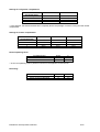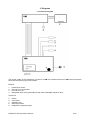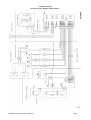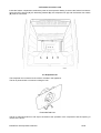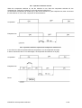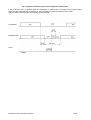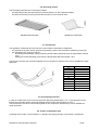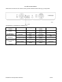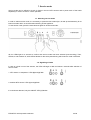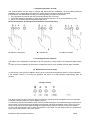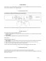
1
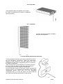
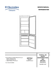
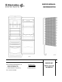
SERVICE MANUAL
REFRIGERATION
EUROFLEC
© ELECTROLUX ZANUSSI S.p.A.
Spares Operations Italy
Corso Lino Zanussi, 30
I - 33080 PORCIA / PN (ITALY)
Fax +39 0434 394096
Publication No.
599 35 40-29
020806
ITZ/SERVICE/AA
With exposed
condenser
EUROFLEC with exposed condenser
2/35
CONTENTS
1. Introduction...................................................................................................................................................5
1.1. Presentation .............................................................................................................................................5
1.2. EUROFLEC: total nofrost.........................................................................................................................6
2. Characteristics..............................................................................................................................................7
2.1. Dimensions and volumes.........................................................................................................................7
2.2. Technical characteristics..........................................................................................................................7
3. Diagrams .......................................................................................................................................................9
3.1 Functional diagram ...................................................................................................................................9
3.2 Electric wiring ..........................................................................................................................................10
4. Components................................................................................................................................................12
4.1. Main components...................................................................................................................................12
4.2. UIB Display board ..................................................................................................................................14
4.3. MB Control and power board .................................................................................................................15
4.4 Foamed connectors seat ........................................................................................................................16
4.5. Evaporator fan........................................................................................................................................16
4.5.1. Operation with door closed..............................................................................................................17
4.5.2. Operation with door opened and compressor switched on.............................................................17
4.5.3. Operation with door opened and compressor switched off.............................................................18
4.6. Defrosting heaters..................................................................................................................................19
4.7. NTC Sensors..........................................................................................................................................19
4.8. Overheating protection...........................................................................................................................19
4.9. Freezer compartment light .....................................................................................................................19
4.10. Evaporator............................................................................................................................................20
4.11. Condenser............................................................................................................................................20
4.12. Flap-operated mechanical thermostat .................................................................................................20
5. Operation.....................................................................................................................................................21
5.1. Normal operation....................................................................................................................................21
5.2. Defrosting...............................................................................................................................................21
6. Control panel...............................................................................................................................................22
6.1. Switching the appliance on and off ........................................................................................................22
6.2. Door alarm .............................................................................................................................................23
6.3. Temperature alarm ................................................................................................................................23
6.4. “Rapid freezing” function........................................................................................................................23
6.5. NTC sensors failure ...............................................................................................................................24
7. Service mode ..............................................................................................................................................25
7.1. Selecting service mode..........................................................................................................................25
7.2. Signalling of faults ..................................................................................................................................25
7.3. Separate activation of loads...................................................................................................................26
7.4. Checking the door switches ...................................................................................................................26
7.5. Deactivation of service mode.................................................................................................................26
8. Demo Mode .................................................................................................................................................27
8.1. Selecting Demo mode............................................................................................................................27
8.2. Main functions ........................................................................................................................................27
8.3. Exiting Demo mode................................................................................................................................27
9. Accessibility of components.....................................................................................................................28
9.1. Refrigerator compartment ......................................................................................................................28
9.2. Displaying board (UIB)...........................................................................................................................30
9.3. Freezer compartment.............................................................................................................................31
9.4. Glass shelves.........................................................................................................................................33
9.5. Air inlets .................................................................................................................................................33
9.6. Control and power board (MB)...............................................................................................................34
10. Main differences between EUROFLEC model and EUROFLEC model with exposed condenser....35
EUROFLEC with exposed condenser
3/35
EUROFLEC with exposed condenser
4/35
1. Introduction
1.1. Presentation
The EUROFLEC with exposed condenser is a new combined refrigerator based on the EUROFLEC
models, but with different versions produced in the Fuenmayor factory in Spain.
The appliance features a single compressor and a total no-frost system. The operating cycles are controlled
electronically. A flap-operated mechanical thermostat controls the temperature inside the refrigerator
compartment.
The EUROFLEC comprises various models which differ from each other in the different size of the freezer
and refrigerator compartments and therefore in the number of shelves and drawers.
The PNCs of the EUROFLEC with exposed condenser begin with 928 405 xxx as for the EUROFLEC
model, therefore, in order to know the model please refer to the specific spare parts list.
EUROFLEC with exposed condenser
5/35
1.2. EUROFLEC: total nofrost
The EUROFLEC is a total no-frost appliance, and as such its operation is based exclusively on the battery
evaporator in the freezer compartment, which cools the air; the fan circulates the air.
A duct embedded in foam channels the cold air into the refrigerator compartment, where the flap-operated
mechanical thermostat regulates the flow of cold air and thus the temperature inside the refrigerator
compartment. The air returns to the freezer compartment through two outlets located at each side of the
vegetable drawer.
Operation of the compressor (switching on and off) is controlled by an NTC sensor located externally (in air)
in the freezer compartment. The electronic system periodically defrosts the ice which accumulates on the
evaporator battery; defrosting terminates when a second NTC sensor, positioned in contact with the
evaporator battery, detects a temperature of +15°C.
The main characteristic of the control system used in the EUROFLEC is the fact that the defrost operating
cycles are not of fixed duration, but calculated on the basis of the time required for defrosting (see chapter
5).
EUROFLEC with exposed condenser
6/35
2. Characteristics
2.1. Dimensions and volumes
The EUROFLEC models are numbered from 1 to 9 (n° 7 has been eliminated):
Model no.
Height
Width
Depth
Gross vol. freezer
Gross vol. fridge
Total gross vol.
mm
mm
mm
litres
litres
litres
1
1950
600
595
94
267
361
2
1800
600
595
126
193
319
3
1800
600
595
94
230
324
4
1800
600
595
157
156
313
5
1650
600
595
94
193
287
6
1650
600
595
126
155
281
8
1750
600
595
94
217
311
9
1950
600
595
126
230
336
2.2. Technical characteristics
Performance:
Refrigerator
Freezer
Energy class
Climate class
Coolant
from 1°C to 10°C
4 stars
A
SN , N , ST
R600a
Compressor:
See the specific spare parts list for each model!
Evaporator fan:
Voltage
(direct current)
Power
V
18
W
3
Defrosting heater:
Power at 230V
W
250
Power at 230V
W
43.5
Drain duct heater:
Safety overheating switches:
Opening
Closure
EUROFLEC with exposed condenser
°C
°C
55
45
7/35
Settings for refrigerator compartment:
Position of
thermostat knob
stand by*
3
5
7
Cut-in
Cut-out
+16°C
+10°C
+7°C
+4°C
+13°C
+7°C
+4°C
+1°C
* In this position, the thermostat does NOT completely blocks the passage of cold air coming from the freezer
compartment.
Settings for freezer compartment:
Position of
thermostat knob
0
3
5
7
Cut-in
Cut-out
Alarm
-15°C
-18°C
-21°C
-23°C
-16°C
-19°C
-22°C
-24°C
-12°C
-12°C
-12°C
-12°C
Normal operating times:
Pre-determined**
Minimum
Maximum
Hours
Hours
Hours
6
4
25
** A six-hour operating cycle is performed each time the appliance is switched on.
Defrosting:
Standard time
Maximum time
Temp. for end of defrosting
EUROFLEC with exposed condenser
Minutes
Minutes
°C
22
30
+15
8/35
3. Diagrams
3.1 Functional diagram
The control system of the EUROFLEC consists of a UIB user interface board and a MB control and power
board with the following inputs and outputs:
INPUTS:
1.
2.
3.
4.
Freezer door switch;
NTC sensor on evaporator;
NTC sensor in air;
Refrigerator door switch (reed element with foam-embedded magnet in door);
OUTPUTS:
5.
6.
7.
8.
9.
buzzer;
compressor;
evaporator fan;
defrosting heaters;
refrigerator compartment light;
EUROFLEC with exposed condenser
9/35
3.2 Electric wiring
( see the specific diagram of the model ! )
EUROFLEC with exposed condenser
10/35
Legend:
2. compressor;
5. overload cut-out;
9. evaporator defrosting heater;
11. drain duct defrosting heater;
13. refrigerator compartment light;
16. freezer door switch;
24. evaporator fan;
26. safety thermal switches;
28. running condenser;
41. display board (UIB);
41a. control and power board (MB);
56. NTC sensor refrigerator (optional);
57. NTC sensor freezer in air;
59. NTC sensor freezer evaporator;
EUROFLEC with exposed condenser
11/35
4. Components
4.1. Main components
1.
2.
3.
4.
5.
6.
7.
8.
9.
10.
11.
display board (UIB);
flap-thermostat;
evaporator battery;
evaporator fan;
defrosting heater;
drain duct heater;
NTC sensor in air;
thermal switch (+55°C) and NTC sensor on evaporator;
control and power board (MB);
condenser;
compressor;
EUROFLEC with exposed condenser
12/35
EUROFLEC with exposed condenser
13/35
4.2. UIB Display board
The UIB display board is placed inside the
refrigerator behind the control panel and
contains the push-buttons, the LEDs and the
refrigerator door switch (reed element).
For the version with ELECTROLUX mark, in the reed element board (B) there are also the two LEDs (red
and green) (A) to display the operation of the refrigerator through the hole drilled on the door.
B
A
EUROFLEC with exposed condenser
14/35
4.3. MB Control and power board
The control and power board is placed in the compressor compartment and contains:
-
A the microprocessor for the control of the appliance;
-
B the section for obtaining the 18 V of direct current to power the fans;
-
C the buzzer for the sound advice of the temperature and open door alarms.
The advice for temperature alarm has an intermittent long-tone sound, while the advice for open door
alarm has a short-tone intermittent sound.
-
the triacs for the outputs of:
compressor
evaporator fan
defrosting heater
drain duct heater
-
NTC safety sensor for the protection of electric components against overheating;
if the temperature of the compressor compartment exceeds 80°C, the compressor stops. The compressor
starts again when the temperature falls below 65°C;
EUROFLEC with exposed condenser
15/35
4.4 Foamed connectors seat
Inside the freezer compartment, behind the panel of the evaporator battery, there are the foamed connectors
where the NTC sensors (A), the defrosting heaters (B), the evaporator fan (C) and the freezer door switch
(D) must be connected.
4.5. Evaporator fan
The evaporator fan is used to let the cold air circulate in the appliance.
The fan is powered with a continuous voltage of 18V.
EVAPORATOR FAN
The fan is actioned (switch on and off) on the basis of the operation of the compressor and the opening or
closure of the doors.
EUROFLEC with exposed condenser
16/35
4.5.1. Operation with door closed
When the compressor switches on, the fan switches on too; after the compressor switches off, the
evaporator fan continues to operate for 2 minutes and then switches off.
As the freezer compartment is cooled only by the cold air ducted in by the evaporator fan, after 30 minutes
the fan switches on, even if the compressor is still switched off.
Compressor
Evaporator fan
4.5.2. Operation with door opened and compressor switched on
If one of the two doors is opened while the compressor is on, the evaporator fan stops.
If after 2 minutes the door is not closed again, the evaporator fan switches on anyway.
Compressor
Evaporator fan
Doors
EUROFLEC with exposed condenser
17/35
4.5.3. Operation with door opened and compressor switched off
If one of the two doors is opened while the compressor is switched off, in the span of 30 minutes during
which also the evaporator fan is switched off, this is activated for 2 minutes after the door closes.
After 2 minutes, the evaporator fan switches off automatically.
Compressor
Evaporator fan
Doors
EUROFLEC with exposed condenser
18/35
4.6. Defrosting heaters
The two heating elements are connected in parallel:
- the defrosting heater (250 W) melts the ice which builds up on the evaporator battery.
- the drain duct heater (43.5 W) prevents the formation of ice in the drain duct.
DEFROSTING HEATER
DRAIN DUCT HEATER
4.7. NTC Sensors
This appliance is fitted with two NTC sensors, both located in the freezer compartment:
- the external (in air) NTC sensor governs the operating cycles of the compressor (switching on and off).
- the evaporator NTC sensor is used for :
- terminating the defrosting cycle by switching off the heating elements when the temperature reaches
15°C;
- starting the forced defrosting cycle when the temperature detected is below –35°C.
The two NTC sensors are connected together as one component, therefore they are not available as single
spare part.
°C
10
5
0
-5
-10
-15
-20
-25
-30
-35
-40
Ohm
5348 ±0.6
6818 ±0.4
8758 ±0.4
11337 ±0.4
14795 ±0.6
19475 ±0.7
25862 ±0.8
34666 ±0.9
46921 ±1
64161 ±1
88577 ±1
4.8. Overheating protection
In case of a malfunction of the control of the end-of defrosting temperature (+15° C), two thermal cut-outs
fitted to the evaporator battery switch the heating elements off at a temperature of +55°C.
The two thermal cut-outs are connected together as one component, therefore they are not available as
single spare part.
4.9. Freezer compartment light
According to the model, 2 normal lamps or 1 halogen lamp supply the light in the freezer compartment.
EUROFLEC with exposed condenser
19/35
4.10. Evaporator
The evaporator fitted to the appliance is located in
the freezer compartment and consists of a traditional
NOFROST battery.
4.11. Condenser
The static exposed condenser is located in
the back of the appliance.
4.12. Flap-operated mechanical thermostat
The flap-operated mechanical thermostat controls the flow of air
into the refrigerator compartment. When the temperature
detected by the external (in air) bulb reaches the cut-in
temperature, the flap opens, thus allowing cold air to enter from
the freezer compartment.
When the temperature in the refrigerator compartment reaches
the cut-out value, the flap re-closes and prevents further air
from being ducted into the refrigerator compartment.
By the STAND-BY position the flap does not stop completely the
cold air to flow in, but regulates the temperature of the freezer
compartment around +15°C (only if in the refrigerator
compartment there is no food, this function is used to keep the
door closed thus avoiding the formation of bad odours).
EUROFLEC with exposed condenser
20/35
5. Operation
5.1. Normal operation
The external (in air) NTC sensor in the freezer compartment controls the compressor’s operating cycles
according to the cut-in and cut-out temperatures for the selected operating mode (warm, normal or cold). As
explained previously, the evaporator fan switches off two minutes after the compressor has stopped; it
remains switched off for 30 minutes, and is then switched on again.
The refrigerator compartment is controlled by the flap-operated thermostat, which opens to allow cold air to
flow in from the freezer compartment.
5.2. Defrosting
The first operating cycle after the appliance is switched on has a fixed duration of 6 hours. After this cycle,
the defrosting cycle starts*: the compressor and the fans are switched off and the heating elements switch
on. When the NTC sensor on the evaporator detects a temperature of +15°C, the heating elements are
switched off and the defrosting cycle is complete.
In any case, the maximum duration of the defrosting cycle is 30 minutes, after which the appliance returns to
normal operation, even if the +15°C temperature has not been reached.
If due to a malfunction the temperature of the evaporator battery should rise to an excessive level, two heat
cut-outs connected in series intervene at +55°C to open the circuit of the heating elements (i.e. switch them
off).
The standard time for the defrosting cycle is 22 minutes. If the time required for the cycle is longer, this
means that a large quantity of ice has accumulated on the evaporator, and the subsequent operating cycle
will have a duration of less than 6 hours. If the time required for the cycle is shorter than 22 minutes, this
means that only a small quantity of ice has accumulated on the evaporator, and the subsequent operating
cycle will have a duration of more than 6 hours. In either case, the duration of the operating cycle is subject
to a lower limit of 4 hours and an upper limit of 25 hours.
In this way, the appliance adapts the duration of the normal operating cycle to the duration of the previous
defrosting cycle: this is the concept of “adaptivity” which distinguishes the EUROFLEC range of fridgefreezers.
Compressor
Evaporator fan
Heaters
N1, N2= normal operating cycle (if N1 is the first: N1=6 hours)
D1, D2= defrosting cycle
A=drain delay = 5 minutes
The compressor does not switch on immediately at the end of the defrosting cycle. Instead, there is a 5minute “drain delay” designed to prevent the formation of ice in the drain duct.
The evaporator fan switches on two minutes after the compressor so that warm air is not circulated inside the
appliance.
The defrosting cycle is forced when the NTC sensor of the evaporator detects a temperature of –35°C.
EUROFLEC with exposed condenser
21/35
6. Control panel
a = freezer regulation knob
b = “door open” alarm button/pilot lamp
c = “temperature” alarm button/pilot lamp
d = “rapid freezing” button
e = ON/OFF button/pilot lamp
f = regulation knob for flap-operated thermostat
6.1. Switching the appliance on and off
To switch the appliance on or off, press and hold down the ON/OFF button (e) for at least 2 seconds.
In order to ensure that the circuit does not remain pressurised, the electronic system introduces a 5-minute
delay in compressor start-up each time the appliance is switched on.
In order to avoid this delay, press the alarm buttons (b and c) simultaneously within 15 seconds after
switching on the appliance.
EUROFLEC with exposed condenser
22/35
6.2. Door alarm
Both doors are fitted with a switch which detects whether
they are open or closed.
The freezer compartment features a button in the top lefthand corner, while the refrigerator compartment is fitted
with an electronic switch, i.e. a reed element fitted to the
control board of the control panel detects the presence or
absence of the magnet embedded in foam in the centre
of the refrigerator door.
r=reed-element, m=magnet
The “door open” alarm lights 4 minutes after the door of the refrigerator compartment is opened, or one
minute after the door of the freezer compartment is opened.
When the alarm is generated, the button/pilot lamp (b) begins to flash and the buzzer sounds. To deactivate
the alarm, it is necessary to press button “b”: the flashing light becomes fixed and the buzzer switches off. If
the door remains open, the alarm resumes flashing and the buzzer sounds again after 4 minutes.
After the third time that the alarm is deactivated, the buzzer switches off definitively and the pilot lamp (b)
remains lit. If the door is not closed, the electronic system switches off the light in the refrigerator
compartment after a further 15 minutes.
6.3. Temperature alarm
The temperature alarm is not connected with the direct reading of the sensor, but it is activated by the
microprocessor which elaborates a simulation of the effective progress of the foodstuff temperature.
If the temperature inside the freezer compartment remain above –12°C for 45 minutes, the “temperature”
alarm (c) is activated.
When the alarm switches on, the button/led (c) starts lightening and the buzzer sounds. In order to switch off
the alarm you need to push button (c): the light stops blinking and remains fixed and the buzzer switches off.
The temperature control is enabled 4 hours after the first start.
After a defrost cycle the alarm is enabled after 90 minutes.
6.4. “Rapid freezing” function
The “rapid freezing” function is selected by pressing the corresponding button/pilot lamp (d) and it is
deactivated automatically after 36 hours. During “rapid freezing” the cut-off temperature is –32°C (the
compressor does not run continuously).
The “rapid freezing” function can be deactivated manually before the 36 hours have elapsed by pressing
button “d” again.
Once the “rapid freezing” function has been selected, a defrosting cycle takes place after 6 hours of
operation; thereafter, the maximum interval between defrosting cycles is 10 hours.
If the “rapid freezing” function is deactivated, the intervals of operation between defrosting cycles return to
the normal periods calculated before the selection of the function.
The electronic control system memorises the time that has elapsed after selection of the “rapid freezing”
function so that, in the event of a temporary power failure, the function does not restart from the beginning,
but from the point at which it was interrupted.
EUROFLEC with exposed condenser
23/35
6.5. NTC sensors failure
When there is a failure in NTC sensors, during normal mode the three LEDs (b), (c) and (d) flash.
The appliance is controlled in the following way:
failure
sensor
Evaporator NTC
sensor
(no adaptivity)
Air NTC sensor
failure
working time
First start
6 hours
During working
latest time before
failure
controlled by evap.
NTC
controlled by evap.
NTC
6 hours
First start
(adaptivity)
During working
Evaporator NTC
sensor + Air NTC
sensor
First start
During working
(no adaptivity)
EUROFLEC with exposed condenser
latest time before
failure
compressor
cycles
controlled by
Air NTC
controlled by
Air NTC
10 min pause
15 min run
latest times before
failure
10 min pause
15 min run
latest times before
failure
defrost time
22 minutes
22 minutes
controlled by evap.
NTC
22 minutes
22 minutes
22 minutes
24/35
7. Service mode
Service mode can be utilised to check for faults in the two NTC sensors and to power each of the loads
separately in order to check for correct operation.
7.1. Selecting service mode
In order to select service mode, it is necessary to press the four buttons (b, c, d and e) simultaneously for at
least 4 seconds within 15 seconds after switching off the appliance.
To exit service mode, press the same buttons again for at least 2 seconds.
All four LEDs light for 5 seconds to confirm that service mode has been selected (auto-checking). Then,
LEDs b, c and d switch off, while LED e flashes for the entire period during which service mode is selected.
7.2. Signalling of faults
In case of a fault in one of the sensors, the LEDs will begin to flash as follows 5 seconds after selection of
service mode:
1. NTC sensor on evaporator: LEDs (b) and (e) flash
2. ambient NTC sensor: LEDs (c) and (e) flash
If no faults are detected, only the ON/OFF LED (e) flashes.
EUROFLEC with exposed condenser
25/35
7.3. Separate activation of loads
The various buttons can be used to activate and deactivate the compressor, fan and heating elements
separately. The corresponding LED remains lit to indicate the load which has been activated.
If the loads are not deactivated manually, the following safety procedure is performed:
1. the compressor and the fan will switch off automatically after 4 minutes
2. the heating elements will switch off when the temperature reaches +15°C (end of defrosting cycle)
3. above +15°C heating elements deactivate after 4 min.
NOTE: the activation of heating elements allows a manual defrosting.
A= ON/OFF compressor;
B= ON/OFF fan;
C= ON/OFF heaters.
7.4. Checking the door switches
The switch of the refrigerator compartment can be checked by noting whether the refrigerator lights switch
on.
To check for correct operation of the freezer compartment switch, check whether the door alarm activates.
7.5. Deactivation of service mode
To exit service mode, press the ON/OFF button (e) for 2 seconds; the appliance returns to normal operation.
If the ON/OFF button is not used, the appliance will return to normal operation automatically after 30
minutes.
6.6 Days counter
The “days counter” function counts the days since the first switching ON of the appliance and it is important
to follow the buttons sequence, without skipping anyone.
To activate this function the ON/OFF button must be pressed during the 5 seconds following the activation of
service mode. The first sounding (long beeps) of the buzzer counts the thousands of day. At the end of the
count during next 10 seconds, after pressing the “rapid freezing” button the buzzer counts the hundreds.
To count the tenths and the unit of days the operation is the same. For the tenths press the “temperature”
button and for the units the “door open” button.
EUROFLEC with exposed condenser
26/35
8. Demo Mode
Demo mode is used to demonstrate the operation of the user interface (control panel) without activating the
various loads (compressor, fan, heating elements).
8.1. Selecting Demo mode
To select Demo mode, press buttons b, d and e simultaneously for at least 2 seconds within 15 seconds
after switching the appliance off by pressing the ON/OFF button.
When Demo mode is selected, the buzzer sounds four times and the LEDs flash simultaneously four times.
8.2. Main functions
The main functions of Demo mode are as follows:
1. the light in the refrigerator compartment must switch on when the door is opened and switch off again
when it is closed.
2. the LEDs light;
3. when the RAPID FREEZING button is pressed, the LED remains lit.
Alarm buttons:
“Temperature alarm” button (c):
1. When pressed once: the LED begins to flash and the buzzer sounds (remains activated also when the
door is closed).
2. When pressed twice within 10 seconds: The LED remains lit (fixed) and the buzzer switches off.
3. After 10 seconds, both the LED and the buzzer are switched off.
The “door” alarm button (b) operates in the same way as the “temperature” alarm (see above).
8.3. Exiting Demo mode
To exit Demo mode, it is necessary to disconnect the appliance from the power supply.
Press the ON/OFF button (e) for at least 2 seconds to enter Demo mode with the appliance switched off
(Demo OFF operation).
EUROFLEC with exposed condenser
27/35
9. Accessibility of components
9.1. Refrigerator compartment
-
remove the panel which covers the thermostat bulb by pushing it first upwards out of its socket.
bend the thermostat bulb to a right-angle;
-
remove the panel which covers the thermostat;
remove the polystyrene protective panel;
-
remove the lamp cover (warning: heat the hooks with an hairdryer in order to avoid their breakage; the
hooks are not replaceable);
remove the thermostat rod cover;
-
EUROFLEC with exposed condenser
28/35
-
remove the four screws which secure the control panel to the cabinet;
remove the control panel;
-
remove the screw which secures the thermostat;
EUROFLEC with exposed condenser
29/35
9.2. Displaying board (UIB)
-
remove the board cover;
remove the thermostat rod;
-
detach the connectors of the PCB;
remove the electronic board;
EUROFLEC with exposed condenser
30/35
9.3. Freezer compartment
-
remove the two screws of the panel which covers the seat of foamed connectors;
-
disconnect the heating element of the drain duct;
unscrew the panel from the evaporator battery;
-
remove the two screws on the front panel; pull the battery assembly outwards to remove it from its
housing, and lay it gently on the bottom of the cell, taking care not to damage the tubes.
remove the polystyrene panel;
-
EUROFLEC with exposed condenser
31/35
-
remove the drain duct (which is pressure-fitted)
remove the fan;
-
raise the evaporator battery slightly and remove the defrosting heater;
these operations make it possible to access the thermal cut-outs (1), the evaporator sensor (2), the
ambient sensor (3) and the freezer compartment door switch.
EUROFLEC with exposed condenser
32/35
9.4. Glass shelves
The glass shelves are secured to the guides by plastic
tabs. To remove the shelves, it is necessary to move
the tabs as shown in detail A.
Two tabs, too, secure the shelf on the vegetable
drawer. To release and remove the vegetable
drawer and glass shelf, it is necessary to rotate the
tabs as shown in detail B.
9.5. Air inlets
The air inlets through which air returns to the freezer
compartment are pressure-fitted. To remove them,
simply lever off using a screwdriver.
EUROFLEC with exposed condenser
33/35
9.6. Control and power board (MB)
-
after disconnecting the connectors on the control and power board, unscrew the screws which secure
the power board to the cabinet;
-
to access the control and power board, unhook the lug (1) and remove the housing (2).
EUROFLEC with exposed condenser
34/35
10. Main differences between EUROFLEC model and EUROFLEC model with
exposed condenser
For further information about EUROFLEC model please refer to Service Manual 599348504.
Please find below a summary of the main differences between EUROFLEC model (writings in italics) and
EUROFLEC model with exposed condenser (with normal writings).
♦
Energy class
EUROFLEC : B ;
EUROFLEC with exposed condenser: A ;
♦
Climate class
EUROFLEC : SN , N , T ;
EUROFLEC with exposed condenser: SN , N , ST ;
♦
Evaporator and condenser fans
EUROFLEC : independent operation ;
EUROFLEC with exposed condenser: it features only the evaporator fan with independent operation;
♦
Condenser
EUROFLEC : vented corrugated condenser located in the compressor compartment;
EUROFLEC with exposed condenser: static exposed condenser located in the back of the appliance.
EUROFLEC with exposed condenser
35/35