1
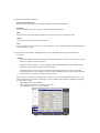
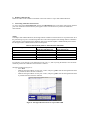
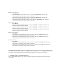
Agilent E5070B/E5071B ENA Series RF Network Analyzers TRL/LRM Calibration First Edition No. 16000-95026 January 2004 Notices The information contained in this document is subject to change without notice. This document contains proprietary information that is protected by copyright. All rightsare reserved. No part of this document may be photocopied, reproduced, or translated toanother language without the prior written consent of Agilent Technologies. Agilent Technologies Japan, Ltd. Component Test Division Kobe 1-3-2 Murotani, Nishi-ku, Kobe, Hyogo, 651-2241 Japan MS-DOSⓇ, WindowsⓇ, Windows 98, Windows NTⓇ, Windows 2000ⓇVisual C++Ⓡ, Visual BasicⓇ, VBA, Excel and PowerPointⓇ are U.S. registered trademarks of Microsoft Corporation. Portions ©Copyright 1996, Microsoft Corporation. All rights reserved. ©Copyright 2004, Agilent Technologies Japan, Ltd. The customer shall have the personal, non-transferable rights to use or copy theVBA macros for the customer’s internal operations.The customer shall use the VBA macros solely and exclusively for their own purposes andshall not license, lease, market, or distribute the VBA macros or modification of any part thereof. Agilent Technologies shall not be liable for any infringement of any patent, trademark,copyright, or other proprietary right by the VBA macros or their use. Agilent Technologiesdoes not warrant that the VBA macros are free from infringements of such rights of thirdparties. However, Agilent Technologies will not knowingly infringe or deliver softwarethat infringes the patent, trademark, copyright, or other proprietary right of a third party. TRL/LRM Calibration Overview The TRL/LRM Calibration VBA Macro lets you perform the 2-, 3-, and 4-port TRL (Through-Reflect-Line), LRL (Line-Reflect-Line), TRM (Through-Reflect-Match), and LRM (Line-Reflect-Match) calibrations for the E5070B/E5071B ENA RF network analyzers. These calibration techniques are generally used in non-coaxial environments such as in-fixture measurements and on-wafer measurements. TRL calibration is performed by using the zero-length through, reflection (short, or open), and line standards. When the non-zero-length through is used instead of the zero-length through standard, the calibration is called LRL. TRM calibration is performed by using the zero-length through, reflection (short, or open), and match (load) standards. When the non-zero-length through is used instead of the zero-length through standard, the calibration is called LRM. TRM and LRM calibrations are suitable for measurements at relatively low frequencies where the line standards of the TRL and LRL calibrations can become physically too long for practical use. The TRL/LRM Calibration VBA Macro allows you to perform calibration over a broad frequency range with a combination of TRM (or LRM) and TRL (or LRL) calibrations while using up to three line standards. Table 1. Key features (comparison with old version) TRL Cal. TRL/LRM Cal. VBA Macro (old version) VBA Macro TRL and LRL calibrations Yes Yes TRM and LRM calibrations No Yes Multiport calibrations Yes Yes Number of line standards Up to 2 Up to 3 Setting negative delay values for cal. stds No Yes Averaging for calibration measurements No Yes Function NOTE We recommend that you use the E5070B/E5071B firmware revision 3.5 and above. To perform TRL/LRM calibration, you need to prepare calibration standards that meet the following requirements: Through (zero-length, or non-zero-length through) Zero-length through - S21 and S12 are defined as equal to 1. - S11 and S22 are defined as equal to zero. Non-zero-length through - Z0 of the through and lines must be the same. - Attenuation need not be known. - Accurate electrical length must be known to set the reference plane. Reflect (short, or open termination) - Reflection coefficient magnitude (optimally 1.0) need not be known. - Phase of the reflection coefficient must be specified within 1/4 wavelength or +/-90 degrees. - Must be the same reflection coefficient on all ports. Line (transmission line) - Electrical length need only be specified within 1/4 wavelength. - Cannot be the same length as the through. Difference between the through and lines must be between 20 degrees and 160 degrees. - Optimal line length is 1/4 wavelength or 90 degrees relative to the through at the center frequency. - Usable bandwidth for a single line standard is 8:1 (frequency span : start frequency). - Attenuation need not be known. Match (load termination) - Must be the same Z0 on all ports. - Z0 of the match standard establishes the reference impedance of the measurement. For more detailed information on the requirements for TRL/LRM standards, refer to the following documents. - Product Note 8510-8A, “Agilent Network Analysis Applying the 8510 TRL Calibration for Non-Coaxial Measurements”, PN 5091-3645E - Product Note 8720-2, “In-fixture Microstrip Device Measurements Using TRL* Calibration”, PN 5091-1943E Installation of TRL/LRM Calibration VBA Macro NOTE Before installing this VBA macro, make sure that your E5070B/E5071B’s firmware revision is 3.5 or above. Installation Procedure 1) Prepare the floppy disk that contains the installation program, “E507X_TRL_LRM_CAL_100.msi”. 2) Reboot the ENA (Turn the ENA’s power OFF, and then turn it ON again). 3) Insert the floppy disk in the ENA. 4) Press [Save/Recall], Explorer to open the Windows Explorer and double-click on the installation program in the A drive. 5) Install the TRL/LRM Calibration VBA Macro by following the instructions of the installation program. 6) The TRL/LRM Calibration VBA Macro program “TRL_LRM_cal.vba” will be installed under the path D:/VBA. 2-port TRL/LRM Calibration Operating Procedure 1. Setting stimulus conditions Select the ENA’s active channel to the one for which you want to perform calibration and set the stimulus conditions of the channel by manual operation. Typical setup items includes: - Start and stop frequencies - Sweep type - Number of points - Source power level - IF Bandwidth - Averaging factor and Averaging ON/OFF For information on the setting procedure, refer to Chapter 3 “Setting Measurement Conditions” in the E5070B/E5071B User's Guide. 2. Starting VBA macro Load and run the TRL/LRM Calibration VBA Macro. Press [Macro Setup], Load&Run, and select TRL_LRM_cal. (Alternatively, you can press [Macro Setup], Load Project, load “TRL_LRM_cal.vba “ at D:/VBA, and press [Macro Run].) 3. Turning off system correction When the message shown in Figure 1 appears, press OK to turn off the system error correction. NOTES - This message does not appear when the system error correction has already been turned off. - System error correction of all channels is turned off. - System error correction can be turned on by [Preset]. Figure 1. Turning off system error correction If you press OK, the TRL/LRM Calibration main control panel appears as shown in Figure 2. Figure 2. TRL/LRM main control panel 4. Selecting ports In the Ports menu, select the test ports for which you want to perform calibration. For example, to perform 2-port TRL/LRM calibration for test ports 1 and 2, select Ports:1-2. NOTE The TRL/LRM Calibration VBA Macro automatically detects the ENA’s active channel, and calibration is performed for the active channel. The macro does not perform calibration for the ENA’s inactive channels. 5. Defining calibration kit Define the values of the calibration standards you use in the calibration. 5-1) Press the Define CalKit key to bring up the calibration kit definition menu shown in Figure 3. Figure 3. Calibration kit definition menu 5-2) Define each standard as follows: Reference impedance Z0 Enter the reference impedance value for the through, match and line standards. Reflection Select the standard type you use (short or open) and enter its delay value. Thru Enter the delay value of the through standard. If necessary, also enter its offset loss value. Match Enter the frequency range of the match standard. Line You can define up to three lines: Line 1, Line 2, and Line 3. For each line standard, enter the delay value and the frequency range. 5-3) Activate the match and line standards you use for the calibration by entering check marks in the checkboxes. NOTES - Reference impedance Z0 of the TRL/LRM Calibration VBA Macro must be set to the same value as the ENA’s system impedance Z0 value. - Calibration reference plane is set to the middle of the through standard. It is not possible to set the calibration reference plane with the reflection standard. - When the frequency ranges of the line and the match overlap, the data of the line is used in the overlapped frequency area. When the frequency ranges of multiple lines overlap, the data of the line measured later is used in the overlapped frequency areas. For example, if you define the calibration kits as shown in Figure 4 and perform the Match, Line 1, and Line 2 measurements in this order, the analyzer uses the following three different calibrations depending on the frequency ranges: - TRM calibration: below 690 MHz - TRL calibration with Line 1: 690 MHz to 4.29 GHz - TRL calibration with Line 2: over 4.29 GHz Figure 4. Calibration kit definition example 5-4) If you want to save the current calibration kit definition, press the Save key and save the definition to your desired file. Saved calibration kit definition files can be recalled by pressing the Recall key. NOTES - If you save the calibration kit definition as “D:/Agilent/Trldata/Default.dat,” the file is handled as the default definition file. The default definition file is automatically recalled when the macro starts. - If you press the Default key, the calibration kit definition is set to the factory default setting (the definition of the 85052C calibration kit). 5-5) Press the Close button to finish defining the calibration kit. 6. Performing calibration measurement If the frequency ranges of match and line standards are correctly defined to cover the ENA’s measurement frequency range, the red warning message “Press [Define CalKit] & Check Match/Line1-3” disappears and the Thru, Reflection, and selected Match/Lines keys appear in the main control panel. NOTES - If the Thru, Reflection, and Match/Lines keys do not appear, go back to the calibration kit definition menu and confirm that the frequency range definitions of match and lines are correctly entered to cover the ENA’s measurement frequency range. - Isolation calibration measurement is not available. 6-1) Press each of the Thru, Reflection, and Match/Lines keys in the main control panel, and then press each calibration measurement key that appears in the User Menu area to perform the calibration measurements. For example, if you perform 2-port TRL/LRM calibration between test ports 1 and 2 by using the Match, Line1 and Line2 standards, perform the calibration measurements as follows: Through measurement: - Press Thru. - Make the through condition for the test ports 1 and 2, and press [ ]Thru 1-2. The through measurement is performed, and an asterisk is indicated. a) Press [ ]Thru 1-2 to perform the thru measurement. b) * indicates when the measurement complete. Figure 5. Performing through calibration Reflection measurement: - Press Reflection. - Connect the Reflection standard to test port 1, and press [ ]Reflection 1. The reflection measurement is performed, and an asterisk appears. - Connect the Reflection standard to test port 2, and press [ ]Reflection 2. The reflection measurement is performed, and an asterisk appears. Match measurement: - Press Match. - Connect the Match standard to test port 1 and press [ ]Match 1. The Match measurement is performed, and an asterisk appears. - Connect the Match standard to test port 2 and press [ ]Match 2. The Match measurement is performed, and an asterisk appears. Line1 measurement: - Press Line1. - Connect the Line1 standard between test ports 1 and 2, and press [ ]Line1 1-2. The Line1 measurement is performed, and an asterisk appears. Line2 measurement: - Press Line2. - Connect the Line2 standard between the ports 1 and 2, and then press [ ]Line2 1-2. The Line2 measurement is performed, and an asterisk appears. 6-2) When all of the necessary calibration measurements are completed, the check marks are indicated on the Thru/Reflection/Match/Lines keys, and the Update CalCoef key appears. Press the Update CalCoef key to activate the measured calibration data. Confirm that the indication “Cor” appears on the display. a) Press Update CalCoef to activate cal. data. b) “Cor” is indicated on the display. Figure 6. Update CalCoef key to activate calibration data 7. Finishing calibration To leave TRL/LRM calibration, click on the close button [X] in the upper right hand corner of the main control panel. Multiport TRL/LRM Calibration Operating Procedure You can make 3- and 4-port TRL/LRM calibration in the same manner as 2-port TRL/LRM calibration. 1. Setting stimulus conditions Select the ENA’s active channel to the one for which you want to perform calibration and set the stimulus conditions of the channel by manual operation. Typical setup items includes: - Start and stop frequencies - Sweep type - Number of points - Source power level - IF Bandwidth - Averaging factor and Averaging ON/OFF For information on the setting procedure, refer to Chapter 3 “Setting Measurement Conditions” in the E5070B/E5071B User's Guide. 2. Starting VBA macro Load and run the TRL/LRM Calibration VBA Macro. Press [Macro Setup], Load&Run, and select TRL_LRM_cal. (Alternatively, you can press [Macro Setup], Load Project, load “TRL_LRM_cal.vba” at D:/VBA, and press [Macro Run].) 3. Turning off system correction When the message shown in Figure 1 appears, press OK to turn off the system error correction. NOTES - This message does not appear when the system error correction has already been turned off. - System error correction of all channels is turned off. - System error correction can be turned on by [Preset]. 4. Selecting ports In the Ports menu, select the test ports for which you want to perform the calibration. For example: - To perform 3-port TRL/LRM calibration for test ports 1, 2, and 3, select Ports:1-2-3. - To perform 4-port TRL/LRM calibration, select Ports:1-2-3-4. Figure 7. Selecting Ports:1-2-3 for 3-port TRL/LRM calibration 5. Defining calibration kit Define the values of the calibration standards in the same manner as 2-port TRL/LRM calibration. 6. Performing calibration measurement 6-1) Press each of the Thru, Reflection, and activated Match/Lines keys in the main control panel, and then press each calibration measurement key that appears in the User Menu area to perform the calibration measurements. NOTE: In multiport TRL/LRM calibration, the through and line calibration measurements are not performed at all of the paths among test ports. The following table shows the measured paths of the through and line calibration measurements. The through and line calibration data of non-measured paths is mathematically derived from the through and line calibration data of the measured paths. Table 2. Measurement paths for Thru and Line calibrations Measurement ports of Measurement paths of Reflection and Match cal. Thru and Line cal. 3-port TRL/LRM cal. for Ports:1-2-3 All ports (1, 2, and 3) 1-2 and 1-3 3-port TRL/LRM cal. for Ports:1-2-4 All ports (1, 2, and 4) 1-2 and 1-4 3-port TRL/LRM cal. for Ports:1-3-4 All ports (1, 3, and 4) 1-3 and 3-4 3-port TRL/LRM cal. for Ports:2-3-4 All ports (2, 3, and 4) 2-3 and 3-4 4-port TRL/LRM cal. All ports (1, 2, 3, and 4) 1-2, 1-3, and 3-4 Calibration type For example, if you perform 3-port calibration for test ports 1, 2, and 3 by using the Match, Line1 and Line2 standards, perform the calibration measurements as follows: Through measurement (Figure 8): - Press Thru. - Make the through condition for test ports 1 and 2, and press [ ]Thru 1-2. The through measurement is performed, and an asterisk is indicated. - Make the through condition for test ports 1 and 3, and press [ ]Thru 1-3. The through measurement is performed and an asterisk is indicated. Figure 8. Through calibration menu for 3-port TRL/LRM Reflection measurement: - Press Reflection. - Connect the Reflection standard to test port 1, and press [ ]Reflection 1. The reflection measurement is performed, and an asterisk is indicated. - Connect the Reflection standard to test port 2, and press [ ]Reflection 2. The reflection measurement is performed, and an asterisk is indicated. - Connect the Reflection standard to the test port 3, and press [ ]Reflection 3. The reflection measurement is performed, and an asterisk is indicated. Match measurement: - Press Match. - Connect the Match standard to test port 1 and press [ ]Match 1. The Match measurement is performed, and an asterisk is indicated. - Connect the Match standard to test port 2 and press [ ]Match 2. The Match measurement is performed, and an asterisk is indicated. - Connect the Match standard to test port 2 and press [ ]Match 3. The Match measurement is performed, and an asterisk is indicated. Line1 measurement: - Press Line1. - Connect the Line1 standard between test ports 1 and 2, and press [ ]Line1 1-2. The Line1 measurement is performed, and an asterisk is indicated. - Connect the Line1 standard between test ports 1 and 3, and press [ ]Line1 1-3. The Line1 measurement is performed, and an asterisk is indicated. Line2 measurement: - Press Line2. - Connect the Line2 standard between test ports 1 and 2, and then press [ ]Line2 1-2. The Line2 measurement is performed, and an asterisk is indicated. - Connect the Line2 standard between test ports 1 and 2, and then press [ ]Line2 1-3. The Line2 measurement is performed, and an asterisk is indicated. 6-2) When all of the necessary calibration measurements are completed, the check marks are indicated on the Thru/Reflection/Match/Lines keys, and the Update CalCoef key appears. Press the Update CalCoef key to activate the measured calibration data. Confirm that the indication “Cor” appears on the display. 7. Finishing multiport TRL/LRM calibration To leave TRL/LRM calibration, click on the close button [X] in the upper right hand corner of the main control panel.