1
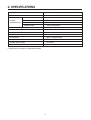
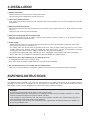
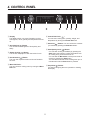
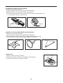
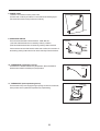
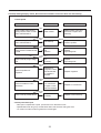
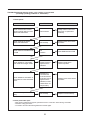
S/M No. :
Service Manual
Microwave Oven
Model: KOC-1C0KB
KOC-1C0KBS
KOC-1C4KB
✔ Caution
: In this Manual, some parts can be changed for improving,
their performance without notice in the parts list. So, if you
need the latest parts information, please refer to PPL(Parts
Price List) in Service Information Center (http://svc.dwe.co.kr).
Feb. 2010
PRECAUTIONS TO BE OBSERVED BEFORE AND
DURING SERVICING TO AVOID POSSIBLE
EXPOSURE TO EXCESSIVE MICROWAVE ENERGY
(a) Do not operate or allow the oven to be operated with the door open.
(b) Make the following safety checks on all ovens to be serviced before activating the magnetron or other
microwave source, and make repairs if necessary: (1) Interlock operation, (2) Proper door closing, (3)
Seal and sealing surfaces (arcing, wear, and other damage), (4) Damage to or loosening of hinges and
latches (5) Evidence of dropping or abuse.
(c) Before turning on power to the microwave oven for any service test or inspection within the microwave
generating compartments, check the magnetron, wave guide or transmission line, and cavity for proper
alignment, integrity, and connections.
(d) Any defective or misadjusted components in the interlock, monitor, door seal and microwave
generation and transmission systems shall be repaired, replaced, or adjusted by procedures described
in this manual before the oven is released to the owner.
TABLE OF CONTENTS
1. SAFETY AND PRECAUTIONS ...................................................................................................................................2
2. SPECIFICATION ..........................................................................................................................................................3
3. INSTALLATION ...........................................................................................................................................................4
4. CONTROL PANEL ......................................................................................................................................................5
5. DISPLAY WINDOW .....................................................................................................................................................6
6. ACCESSORIES ...........................................................................................................................................................7
7. INTERLOCK MECHANISM AND ADJUSTMENT ....................................................................................................10
8. WIRING PROCEDURE ..............................................................................................................................................11
9. WIRING DIAGRAM ....................................................................................................................................................12
10. ELECTRICAL PARTS LIST ....................................................................................................................................13
11. DISASSEMBLY AND ASSEMBLY ..........................................................................................................................14
12. COMPONENT TEST PROCEDURE .......................................................................................................................27
13. TROUBLE SHOOTING GUIDE ...............................................................................................................................30
14. PRINTED CIRCUIT BOARD ...................................................................................................................................36
1
1. SAFETY AND PRECAUTIONS
1. FOR SAFE OPERATION
Damage that allows the microwave energy (that cooks or heats the food) to escape will result in poor cooking and may
cause serious bodily injury to the operator.
IF ANY OF THE FOLLOWING CONDITIONS EXIST, OPERATOR MUST NOT USE THE APPLIANCE.
(Only a trained service personnel should make repairs.)
(1) A broken door hinge.
(2) A broken door viewing screen.
(3) A broken front panel, oven cavity.
(4) A loosened door lock.
(5) A broken door lock.
The door gasket plate and oven cavity surface should be kept clean.
No grease, soil or spatter should be allowed to build up on these surfaces or inside the oven.
DO NOT ATTEMPT TO OPERATE THIS APPLIANCE WITH THE DOOR OPEN.
The microwave oven has concealed switches to make sure the power is turned off when the door is opened.
Do not attempt to defeat them.
DO NOT ATTEMPT TO SERVICE THIS APPLIANCE UNTIL YOU HAVE READ THIS SERVICE MANUAL.
2. FOR SAFE SERVICE PROCEDURES.
1. If the oven is operative prior to servicing, a microwave emission check should be performed prior to servicing the
oven.
2. If any certified oven unit is found to servicing, a microwave emission check should be performed prior to servicing the
oven.
(1) inform the manufacturer, importer or assembler,
(2) repair the unit at no cost to the owner,
(3) attempt to ascertain the cause of the excessive leakage,
(4) tell the owner of the unit not to use the unit until the oven has been brought into compliance.
3. If the oven operates with the door open, the service person should tell the user not to operate the oven and contact
the manufacturer immediately.
IMPORTANT
The wire in this mains lead coloured in accordance with the following code.
Green-and-yellow : Earth
Blue
: Neutral
Brown
: Live
As the colours of the wires in the mains lead of this appliance may not correspond with the coloured markings
identifying the terminals in your plug, proceed as follows:
The wire which is coloured green-and-yellow must be connected to the terminal in the plug which is marked with the
letter ‘E’, earth symbol or coloured green-and-yellow.
The wire which is coloured blue must be connected to the terminal which is marked with the letter ‘N’ or coloured
black.
The wire which is coloured brown must be connected to the terminal which is marked with the letter ‘L’ or coloured
red.
NOTE : This oven is designed for counter-top use only.
2
2. SPECIFICATIONS
MODEL
KOC-1C0KB / KOC-1C0KBS / KOC-1C4KB
POWER SUPPLY
230V~50Hz, SINGLE PHASE WITH earthing
MICROWAVE
1450W
POWER
GRILL
1250W
CONSUMPTION
CONVECTION
2650W
COMBINATION
2750W, MAX 2900W
MICROWAVE ENERGY OUTPUT
800W (IEC705)
MICROWAVE FREQUENCY
2450MHz
OUTSIDE DIMENSIONS (W X H X D)
524X375X477mm(20.63X14.76X18.78in)
CAVITY DIMENSIONS (W X H X D)
400x233x365mm(15.75x9.17x14.37in)
NET WEIGHT
Approx. 25kg(55.06 lbs)
FUNCTION SELECTIONS
MICROWAVE/ GRILL/ CONVECTION/ COMBINATION
POWER SELECTIONS
10 LEVELS
CAVITY VOLUME
1.3 Cu.Ft (34 ℓ)
* Specifications are subject to change without notice.
3
3. INSTALLATION
1. Steady, flat location
This microwave oven should be set on a steady, flat surface.
This microwave oven is designed for counter top use only.
2. Leave space behind and side
All air vents should be kept a clearance. If all vents are covered during operation, the oven may overheat and, eventually,
cause failure.
3. Away from Radio and TV sets
Poor television reception and radio interference may result if the oven is located close to a TV, Radio, antenna or feeder
and so on.
Position the oven as far from them as possible.
4. Away from heating appliances and water taps
Keep the oven away from hot air, steam or splash when choosing a place to position it, or the insulation might be
adversely affected and breakdowns occur.
5. Power supply
• Check your local power source. This microwave oven requires a current of approximately 15 amperes, 230V, 50Hz.
• Power supply cord is about 1.5 meters long.
• The voltage used must be the same as specified on this oven. Using a higher voltage may result in a fire or other
accident causing oven damage. Using low voltage will cause slow cooking. We are not responsible for damage
resulting from use of this oven with a voltage of ampere fuse other than those specified.
• This appliance is supplied with cable of special type, which, if damaged, must be repaired with cable of same type.
• Such a cable can be purchased from DAEWOO and must be installed by a Qualified Person.
6. Examine the oven after unpacking for any damage such as:
A misaligned door, broken door or a dent in cavity.
If any of the above are visible, DO NOT INSTALL, and notify dealer immediately.
7. Do not operate the oven if it is colder than room temperature.
(This may occur during delivery in cold weather.) Allow the oven to become room temperature before operating.
EARTHING INSTRUCTIONS
This appliance must be earthed. In the event of an electrical short circuit, earthing reduces the risk of the electric shock by
providing an escape wire for the electric current. This appliance is equipped with a cord having a earthing wire with a
earthing plug. The plug must be plugged into an outlet that is properly installed and earthed.
WARNING
Improper use of the earthing plug can result in a risk of electric shock.
Consult a qualified electrician of serviceman if the earthing instructions are not completely understood, or if doubt
exists as to whether the appliance is properly earthed, and either:
If it is necessary to use an extension cord, use only a 3-wire extension cord that has a 3-blade earthing plug, and a
3-slot receptacle that will accept the plug on the appliance.
The marked rating of the extension cord should be equal to or greater than the electrical rating of the appliance, or
Do not use an extension cord.
4
4. CONTROL PANEL
1 Display
The display shows you some information such as
cooking time, menu, quantity and temperature and so
on.
6 Control Dial Knob (
):
You can enter cooking time, quantity, weight, and
temperature by turning the Control Dial knob.
7 Selection( ) Button: You can confirm the contents
you entered by pressing the Selection button.
2 Quick defrost( ) Button
You can defrost a 500 grams of food quickly and
easily.
8 Start/Speedy Cook ( ) Button:
- You can start cooking immediately by pressing the
Start button after entering cooking information such
as cooking time, power level and so on.
- You can start the Microwave cook at power level 10
quickly by pressing the Start button.
You can add 30 seconds to the cooking time up to 5
minutes each time the Start button is pressed.
3 Steam cleaning( ) Button
This function helps you to clean the inside of oven.
4 Deodorization( ) Button
The oven has a special function to blow off smells in
the oven.
5 Menu Dial Knob :
You can choose a cooking menu by turning the Menu
Dial knob.
9 Stop/Clear( ) Button:
It is used for stopping the oven operation or clearing
the display.
5
1 Display window
5 Icons of cooking menu
The display shows you some cooking information such
as cooking time, clock, temperature, quantity and so on.
: It means Quick defrost.
during Quick defrosting.
lights in the display
: It means Steam cleaning.
during Steam cleaning.
2 Icons of cookware
lights in the display
: It means Deodorization.
during Deodorization.
: It means a Steam bowl. If
lights in the display
, use a steam bowl for cooking.
(This is optional feature.)
lights in the display
: It means Convection cook.
during Convection cooking.
lights in the display
: It means a Grill rack. If
lights in the display ,
use a grill rack for cooking.
: It means Grill cook.
Grill cooking.
: It means a Metal tray. If
lights in the display ,
use a metal tray for cooking.
: It means Combination cook.
lights in the
display during Combination cooking.
lights in the display during
: It means Microwave cook.
during Microwave cooking.
3 Icons of operation guide
: It means the Control dial knob. If
the control dial knob.
blinks, turn
: It means the Selection button. If
the selection button.
blinks, press
: It means the Start button. If
start/speedy cook button.
: It means Auto defrost.
during Auto defrosting.
: It means Auto cook.
Auto cook.
: It means Instant cook.
during Instant cook.
blinks, press the
: It means Fermentation.
during Fermentation.
lights in the display
lights in the display
lights in the display during
lights in the display
lights in the display
: It means Steam cook.
lights in the display
during Steam cook. This is optional feature.
4 Icons of voice guide function
: It means Mexican cook.
lights in the display
during Mexican cook. This is optional feature.
: It means the Voice guide function. If the voice
guide function is activated,
turns on in the
display.
(Refer to “Setting the volume level” on the page 9.)
: It means Memory cook.
during Memory cook.
lights in the display
: It means Preheating.
lights in the display
during preheating in Convection cooking.
6
6. ACCESSORIES
This oven is equipped with several accessories. They can be used in various ways to facilitate cooking.
1
2
3
4
1 Metal Tray - Put food or proper cookware on the metal tray.
NOTE : Metal Tray is attached to the left cushion.
2 Grill Rack - Put the grill rack on the metal tray.
It should be always used with the metal tray for cooking.
3 Grill Tray - Put food or proper cookware on the grill tray
NOTE : Grill Tray is attached to the right cushion.
4 Rotisserie - It can be used in Auto cook menu 3
(Please, refer to the next page about using of rotisserie)
■ HOW TO USE THE ACCESSORIES OF COOKING
■ Metal Tray
■ Grill Rack
■ Grill Tray
■ Rotisserie
Fork
Fixture
Bar
• Microwave cooking
• Auto defrosting
• Quick defrosting
• Fermentation
• Grill cooking
• Put the grill rack on the
metal tray.
• It should be always used
with the metal tray for
cooking.
• Memory cooking
• Convection cooking
• Auto cook menu: 3, 5
• Auto cook menu: 1, 2, 4, 6
• Instant cook menu: 1, 5
• Instant cook menu: 2, 3, 4
7
• Auto cook menu: 3
7. INTERLOCK MECHANISM AND ADJUSTMENT
■ HOW TO USE THE ACCESSORIES OF COOKING
1 Insert Chicken into rotisserie
5 Put the base bowl of steam bowl on the center of
bottom The base bowl of steam bowl is usually used to
catch any fat and/or grease dripping from food placed
directly on the grid or to cook food directly.
4
3
2 Fix forks by turing the Fixture
5
3 Insert the right shaft of bar into the motor
6 Start cooking by Auto cook menu 3
For detail operation, refer to the page 14.
4 Put the left shaft of bar on the holder of rotisserie.
WARNING: • Rotisseri is not a toy. Keep it away from children
• The oven and rotisseri are very hot after cooking.
• Use a thick oven glove while you are handing food or accessories.
NOTE: • The wide glass(heat resistant) utensil can be used instead of the base bowl in autocook menu 3.
• When you operate the oven at the first time, smoke and bad odor might come out from the oven. Then, it will be helpful to
operate the oven in Convection cook at 250˚C with no food for about 10 minutes.
• The cooling fan could be operated for a few minutes after cooking for the safety. The display will show “Cool” and “0” or
“current time” in turns while the cooling fan is operated.
8
STEAM BOWL GUIDE (Optional)
■ Component parts of Steam bowl
Lid
Steam plate
Base bowl
WARNING: • The oven and steam bowl is very hot after cooking.
• Use thick oven globes while you are handing food or
accessories.
Tips : You can cook small items faster than larger ones. And
uniform sized food will be cooked more evenly.
■ How to use Steam bowl
about
200~300ml
Pour the required amount of
water into the base bowl.
(about 200~300ml)
Put the steam plate on the
base bowl. And put
ingredients on it not to
overlap each other.
Cover with the lid. Make
sure that the edge of lid is
adjusted to the base bowl's.
■ Important Safety Instructions
• Do not use this Steam bowl with a different product or model.
• Do not attempt to operate the oven without water or food inside.
• Before you use the Steam bowl, pour about 200 ~ 300ml of water into base bowl.
If water is not enough in the base bowl, it could cause the oven to be damaged or fire to happen.
• Do use the Steam bowl only for its intended use as described in this manual.
This is not intended for laboratory or industrial use.
• Do not operate the oven if the Steam bowl is damaged.
• Do not use the Steam bowl without the lid or the base bowl.
• Make sure that you install the lid onto the base bowl so that it fits into the steam plate.
• Do not touch the oven and steam bowl not wearing oven gloves.
Because they get very hot after cooking, they can cause burns.
• Do not use outdoors.
• The eggs or the chestnuts would be exploded without the lid and the steam plate.
• Read and follow the specific precautions in the instruction of steam cooking guide.
■ Care and Cleaning
• Do not use abrasive cleaning products or solvents.
• Clean the appliance with soapy water.
• Do not immerse the Steam bowl into the water for a long time.
• Do not place the Steam bowl nearby a hot gas or electric burner or in a extremely heated oven.
9
Put the steam bowl on the
bottom.
7. INTERLOCK MECHANISM AND ADJUSTMENT
CONDITION : DOOR OPEN
LEFT
RIGHT
RED/RED
INTERLOCK
MONITOR
SWITCH
RED/RED
BLACK/BLUE
BLUE
YELLOW
WHITE/BLUE
BLUE
WHITE
DOM
SWITCH
PRIMARY
INTERLOCK
SWITCH
HOOK
CONDITION : DOOR CLOSE
LEFT
RIGHT
10
8. WIRING PROCEDURE
MAIN PCB
1
2
5
3
4
8
7
6
LOCATION
PART NAME
WIRING COLOR
FUNCTION
1
MW RELAY
Black & White, Black & White
Control M/W
2
HALOGEN HEATER RELAY
White & Red, Black
Control halogen heater(Side heater)
3
TOP HEATER RELAY
White & Black, Black
Control heater top
4
CONVECTION RELAY
Blue, Blue
Control heater back
5
SLOW ACTING RELAY
Blue, Blue
Prevent the current of oven from rising rapidly in
Microwave Mode
6
D.O.M CONNECTOR
Blue, Green(Middle), Blue
D.O.M(DOOR OPEN MONITOR) helps the
MICOM checking the Interlocking system of DOOR
7
SUB RELAY
8
THERMISTER CONNECTOR
NO. 1 : Red
NO. 3 : White
NO. 5 : Black
NO. 7 : Blue
NO. 9 : Grey
White, White
11
NO. 1 & 3 : Supply power to PCB
NO. 5 : Convection motor
NO. 7 : Blower-Motor
NO. 9 : Lamp
Temperature sensor
N
L
GE
BL
BR
N
L
FUSE
12
BK
BK
GN
N
L
POWER SUPPLY :
SINGLE PHASE
ONLY
LINE FILTER ASS'Y
SPEAKER
NC.
YW
NO.
BL
BM
BK
L.V. TRANSFORMER
PRIMARY
INTERLOCKSWITCH
COM.
WH RD
MGT
THERMAL CUT-OUT
DOOR : CLOSED
COOK : OFF
[CONDITION]
WH
RD
BL
FM
RD
BL
CM
BK
CONVECTION HEATER
WH
BL
BK
RD
BK
BK
RD
BL
BL
WH
OL:LAMP
FM:BLOWER MOTOR
CM:CONVECTION MOTOR
ST:STIRRER MOTOR
BM:BARBEQUE MOTOR
NOTE :
NC.
BK
BK
BK
BL
RD
ST
BL
WH
YW
RD
BL
D.O.M. SWITCH
GY:GRAY
S/N
BL:BLUE
GE:GREEN/YELLOW
GN:GREEN
WH
WH
H.V.
FUSE
H.V. DIODE
H.V.
CAPACITOR
: 3513510960
HALOGEN SLOW ACTING
HEATER RELAY
RELAY
CONTROL P.W.B. ASS'Y
SECONDARY
INTERLOCK SWITCH
RD
TOP HEATER
THERMAL
CUT-OUT
POWER
RELAY
RD
RD:RED
WH:WHITE
BK:BLACK
YW:YELLOW
BR:BROWN
FAN CONVECTION
LAMP
T/MOTOR RELAY FAN
CONVECTION TOP
RELAY
RELAY
HEATER
HEATER
RELAY
RELAY
GY
OL
RD
CONVECTION HEATER
THERMAL CUT-OUT
TOP HEATER
NO.
HALOGEN HEATER (TOP)
COM.
PTC
RD
HIGH VOLTAGE
TRANSFORMER
THERMISTOR
INTERLOCK
MONITOR SWITCH
9. WIRING DIAGRAM
MAGNETRON
NO
PART CODE
PART NAME
SPECIFICATION
1
3966031300
MOTOR SYNCRO
SM16F -HK36T1FY
1
2
3518303901
CAPACITOR HV
2100VAC 1.1UF #187 75M +3,-0
1
3
3518400400
DIODE HV
HVR-1X-3AB 12KV #187
1
4
3513601600
LAMP
BL 240V 25W T25 C7A H187
1
5
3512783930
HARNESS MAIN
KOC-1C4K5SC1
1
6
3512783940
HARNESS CONVECTION AS
KOC-1C4K5SC1
1
7
3518701900
FUSE H.V
5kV 0.8A T.H.V. 060T
1
8
4415A17352
SW MICRO
SZM-V16-FA-63
1
9
4415A66910
SW MICRO
SZM-V16-FA-61
2
10
3512808510
HEATER (상히터)
230V 1200W
1
11
3518125200
TRANS HV
R1S58D
1
12
3518606880
NOISE-FILTER
DWLF-M27-4
1
13
35113A5Q0U
CORD POWER AS
3X1.5 80X80 120-RTML 1.55M
1
14
3518003710
MAGNETRON
2M218HFL 6CF
1
15
3518907010
THERMOSTAT(마그네트론)
OFF:120 ON:60 H #187 ,BRAKET
1
16
3518904000
THERMOSTAT(상히터)
OFF:120 ON:105 V #187 BRAKET
1
17
3518903200
THERMOSTAT(후히터)
OFF:145 ON:135 V #187 BRAKET
1
18
3963513950
MOTOR SHADED POLE
230V 50HZ OEM-10DWC2-T08
1
19
3512808000
HEATER(후히터)
230V 1400W / 220V 1280W KAWAI
1
20
3963320200
MOTOR BLOWER
220V 60HZ OEB-2505B1
1
21
3512803260
HEATER HALOGEN
230V 300W 170MM
1
22
3966830920
MOTOR SYNCRO
SSM-23H AC220V~240V
1
13
Q’TY
REMARK
11. DISASSEMBLY AND ASSEMBLY
- Cautions to be observed when trouble shooting.
Unlike many other appliances, the microwave oven is high-voltage, high-current equipment. It is completely safe
during normal operation. However, carelessness in servicing the oven can result in an electric shock or possible
danger from a short circuit. You are asked to observe the following precautions carefully.
1. Always remove the power plug from the outlet before servicing.
2. Use an insulated screwdriver and wear rubber gloves when servicing the high voltage side.
3. Discharge the high voltage capacitor before touching any oven components or wiring.
(1) Check the grounding.
Do not operate on a two-wire extension cord.
The microwave oven is designed to be used while grounded.
It is imperative, therefore, to make sure it is grounded
properly before beginning repair work.
(2) Warning about the electric charge in the high voltage capacitor.
For about 30 seconds after the operation has stopped, electric
charge remains in the high voltage capacitor.
When replacing or checking parts, short between oven chassis
and the negative high terminal of the high voltage capacitor by
using a properly insulated screwdriver to discharge.
4. When the 15A fuse is blown out due to the operation of the monitor
switch; replace primary interlock switch, secondary interlock switch
and interlock monitor switch.
5. After repair or replacement of parts, make sure that the screws are
properly tightened, and all electrical connections are tightened.
6. Do not operate without cabinet.
CAUTION : Service personnel should remove their watches whenever working close to or replacing the magnetron.
WARNING : When servicing the appliance, take care when touching or replacing high potential parts because of
electrical shock or exposing microwave. These parts are as follows - HV Transformer, Magnetron,
HV Capacitor, HV Diode.
14
12. DISASSEMBLY AND ASSEMBLY
1. To remove cabinet
1) Remove four screws on cabinet back.
2) Push the cabinet backward.
2. To remove door ASS'Y
1) Remove each two screws (total 4EA) on left and right
sides.
2) Remove spring hinges in both sides.
* It is easy to remove the bottom of spring firstly and to
set the top of spring firstly.
3) Remove HINGE TOP *R and HINGE TOP *L.
* HINGE TOP must be connected to the inside of DOOR.
4) Reverse the above steps for reassembly.
3. To remove C-Panel ASS'Y
1) Remove the screws.
2) Slide the C-PANEL in the direction of left and pull out
forward.
3) Reverse the above steps for reassembly.
15
SPRING HINGE
4. EXPLODED VIEW AND PARTS LIST OF DOOR ASS'Y.
NO.
PART CODE
PART NAME
DESCRIPTION
A01
3512603830
HANDLE DOOR *O
ABS SPRAY KOC-1C0KQS
1
A02
3515309510
SUPPROTER HANDLE
PO T1.6
1
A03
3512603910
HANDLE DOOR *I
ABS
1
A04
3517010720
BARRIER SCREEN *O
TEMP GLASS T3.2 WHITE PATTERN
1
A05
3512210320
FRAME DOOR
PC+ABS HR-5007A SPRAY KOC-1C0KQS
1
A06
3513304620
INSULATOR GLASS
T2.0 TEMPERED
1
A07
3513003100
HOLDER INNER GLASS *R
PBT
1
A08
3511728810
DOOR PAINTING AS
KOC-1C0KQS
1
A09
3512902020
HINGE HOOK
SWRM3
2
A10
3513102100
HOOK
ZN DIE CASTING
2
A11
3512303000
GASKET DOOR
PBT
1
A12
3512902000
HINGE UNDER *L AS
KOC-1C0KQS
1
A13
3512902010
HINGE UNDER *R AS
KOC-1C0KQS
1
A14
3515103600
SPRING HOOK
PW1
2
A15
7S312X40A1
SCREW SPECIAL
T1 TRS 4X10 SE MFZN
3
A16
7S312X40A1
SCREW SPECIAL
T1 TRS 4X10 SE MFZN
4
A17
3513003100
HOLDER INNER GLASS *R
PBT
1
A18
7122401211
SCREW TAPPING
T2S TRS 4X12 MFZN
2
A19
7121401211
SCREW TAPPING
T2S PAN 4X12 MFZN
2
A20
7121400612
SCREW TAPPING
T2S PAN 4X7 MFZN
3
16
Q'TY
REMARK
5. EXPLODED VIEW AND PARTS LIST OF CONTROL PANEL.
B01
B02
B03
B04
B05
B06
B07
B08
B09
B11
PART NAME
DESCRIPTION
B10
NO.
PART CODE
Q'TY
B01
3511620110
DECORATOR C-PANEL
SAN T1.5 WHITE
1
B02
3516725920
CONTROL-PANEL
PC+ABS HR5007A SPRAY KOC-1COKQS
1
B03
3516913020
BUTTON FUNCTION-A
ABS COATING
2
B04
3516913010
DECORATOR KNOB
ABS COATING
2
B05
3513411530
KNOB VOLUME
ABS SPRAY KOC-1C0KQS
2
B06
3514333100
PCB MAIN AS
KOC-1C0KQS
1
B07
3514333200
PCB SUB1 AS
KOC-1C0KQS(GENERAL)
1
B08
3514333300
PCB SUB2 AS
KOC-1C0KQS
1
B09
3514333400
PCB SUB3 AS
KOC-1C0KQS
1
B10
7621301011
SCREW TAPPING
T2S PAN 3X10 PW MFZN
9
B11
7122401211
SCREW TAPPING
T2S TRS 4X12 MFZN
7
17
REMARK
6. To remove high voltage capacitor
1) Remove a screw which secure the grounding ring
terminal of the H.V.diode and capacitor holder.
2) Remove the H.V.capacitor from the capacitor holder.
3) Remove the H.V.diode from the H.V.Capacitor.
4) Reverse the above steps for reassembly.
Capacitor Holder
H.V.Capacitor
H.V.Diode
NOTE: Connecting procedure of magnetron, H.V.
transformer, H.V, diode, H.V. fuse, H.V.
capacitor.
1) Connect two terminals(1) from H.V. transformer to
magnetron using the all-in-one connector.
2) Connect the connector, which connected two wires(2)
from H.V. transformer, to H.V. capacitor .
3) Connect H.V. diode(3) to H.V. capacitor in same
location with terminal 2
4) The one direction of 4 connect to secondary terminal of
H.V. transformer and another connect to H.V
capacitor(except of terminal 2, 3)
18
7. TO REMOVE MAGNETRON
1) Remove a screw which secure the magnetron.
2) Remove the magnetron.
3) Reverse the above steps for reassembly.
NOTE: Never install the magnetron without the metallic gasket plate which is packed with each magnetron to
prevent microwave leakage. Whenever repair work is carried out on magnetron, check the microwave
leakage. It shall not exceed 4mW/cm2 for a fully assembled oven with door normally closed.
Metallic
gasket
plate
Wave guide Magnetron antenna
Magnetron
antenna
Cooling fin
Filament
terminal
<MAGNETRON>
Metallic gasket plate
19
8. TO REMOVE BLOWER MOTOR
1) Remove a screw which secure the cover motor blower.
2) Remove a screw which secure the blower motor.
3) Remove the cover motor blower.
4) Remove the wire which connecting the blower motor
5) Push a latch of blower motor and draw backward
6) Reverse the above steps for reassembly.
COVER MOTOR BLOWER
BLOWER MOTOR
LATCH
9. TO REMOVE H.V.TRANSFORMER
1) Remove four screws holding the H.V.transformer.
2) Remove the H.V.transformer.
3) Reverse the above steps for reassembly.
20
10. TO REMOVE TOP HEATER
1) Remove a nut which secure the top heater.
2) Pull out the heater.
11. TO REMOVE HALOGEN HEATER
(SIDE HEATER)
Halogen heater cover
1) Remove a screw in insulator heater top.
2) Remove the wire which connecting the halogen heater.
3) Remove a screw on cover of halogen heater.
4) Remove a bracket of halogen heater.
5) Remove a halogen heater.
6) Reverse the above steps for reassembly.
21
Halogen heater
braket
12. TO REMOVE STIRRER FAN
1) Remove a screw to the cover wave guide.
2)Push the fixture supporter in top plate.
3) Remove a holder stirrer from the stirrer motor.
4) Rotate the holder stirrer about 45°C and reassemble from
groove of the stirrer blade.
5) Remove holder stirrer and supporter stirrer.
6) Reverse the above steps for reassembly.
Holder Stirrer
Supporter
Stirrer
Fixture
Supporter
Stirrer
Stirrer Blade
COVER
WAVE
GUIDE
13. TO REMOVE NOISE FILTER
1) Remove a screw which secure the noise filter.
2) Remove a screw which earth to wire from noise filter.
3) Remove a noise filter from the bracket noise filter.
14. TO REMOVE SPEAKER
1) Remove a screw which secure the base plate and
speaker holder
2) Remove speaker holder and speaker
22
15. EXPLODE VIEW AND PARTS LIST OF BACK HEATER ASSEMBLY
C01
C02
C03
C15
C04
C14
C05
C06
C13
C07
C12
PART NAME
C11
DESCRIPTION
C08
C10
NO.
PART CODE
C01
7S628W40X1
NUT HEX
C02
3511800700
FAN CONVECTION
SA1D T0.5
1
C03
3512808000
HEATER
230V 1400W KAWAI
1
C04
3512806000
HEATER REFLECTOR
SA1D T0.5
1
C05
3511409800
COVER HEATER *B
SA1D-80 T0.5
1
C06
3513303400
INSULATOR HEATER *B
SBHG-1 T0.5
1
C07
7113400814
SCREW TAPPING
T1 BIN 4X8 MFNI
6
C08
3963513950
MOTOR SHADED POLE
230V 50HZ ,OEM-10DWC2-T08
1
C09
7121400611
SCREW TAPPING
T2S PAN 4X6 MFZN
1
C10
3518903200
THERMOSTAT
OFF:145 ON:135 V #187
1
C11
7601400811
SCREW MACHINE
PAN 4X8 PW MFZN
2
C12
3512783940
HARNESS CONVECTION AS
KOC-1C4K5SC1
1
C13
3513002300
HOLDER HEATER
SUS304 T0.5
3
C14
7113400814
SCREW TAPPING
T1 BIN 4X8 MFNI
3
C15
7400104011
WASHER PLAIN
PW-1-4 MFZN
1
NUT FLANGE M4X0.7P MFZN
23
Q'TY
1
C09
REMARK
16. TOTAL ASSEMBLY AND PARTS LIST
F01
F02
F03
F04
F05
F06
F07
F08
F09
F10
F11
F12
F13
F70
F71
F63
F64
F84
F60
F61
F59
F41
F65
F58
F83
F62
F57
F66
F67
F48
F49
F51
F52
F50
F82
F14
F68
F55
F45
F47
F53
F69
F46
F54
F81
F44
F56
F77
F76
F72
F43
F15
F40
F74
F73
B00
F38
F39
F42
A00
F78
F16
F79
F37
F80
F36
F75
F34
F33
F32
F31
F30
F29
F28
F35
24
F27
F26
F25
F24
F23
F22
F21
F20
F19
F18
F17
NO.
A00
B00
PART CODE
3511730010
PART NAME
Q'TY
KOC-1C0KB or KOC-1C0K5SC2
1
3511730020
KOC-1C0KBS or KOC-1C0K5SC3
1
3511730000
KOC-1C4KB or KOC-1C4K5SC1
1
KOC-1C0KB or KOC-1C0K5SC2
1
PKCPSWAL40
DOOR AS
DESCRIPTION
CONTROL-PANEL AS
PKCPSWAL70
KOC-1C0KBS or KOC-1C0K5SC3
1
PKCPSWALA0
KOC-1C4KB or KOC-1C4K5SC1
1
F01
3516120000
CAVITY AS
KOC-1C0KQS
1
F02
3510611600
BRACKET NOISE FILTER
PP
1
F03
3518606880
NOISE FILTER
DWLF-M27-4 250V 15A
1
F04
3517505200
PROTECTOR WIRE
STS T0.6
1
F05
3513001900
HOLDER HV CAPACITOR
SECC T0.5
1
F06
3518303901
CAPACITOR HV
2100VAC 1.1UF #187+3
1
F07
3518701900
FUSE HV
5KV 0.8A T.H.V.060T
1
F08
3518125200
TRANS HV
R1S58D
1
F09
3513005300
HOLDER LAMP
STS T0.4
1
F10
7S312X40A1
SCREW SPECIAL
T1 TRS 4X10 SE MFZN
2
F11
35113A5Q0U
CODE POWER AS
3X1.5 80X80 120-RTML 1.55M
1
F12
3517505210
PROTECTOR HEAT
STS T0.6
1
F13
7S312X40A1
SCREW SPECIAL
T1 TRS 4X10 SE MFZN
2
F14
3510810920
CABINET AS
KOC-1C0KQS
1
F15
3511415000
COVER *B
SBHG T0.8
1
F16
3512808420
HEATER *B AS
KOC-1C0K5SC2
1
F17
3963320200
MOTOR BLOWER
220V~240V 60Hz OEM-2505B1
1
F18
7S312X40A1
SCREW SPECIAL
T1 TRS 4X10 SE MFZN
2
F19
3511415100
COVER EXHAUST
GAL T0.5
1
F20
3511415200
COVER MOTOR BLOWER
PP(TB-53)
1
F21
7121400611
SCREW TAPPING
T2S PAN 4X6 MFZN
1
F22
3518003710
MAGNETRON
2M218HFL 6CF
1
F23
3512527810
GUIDE AIR
SECC T0.5
1
F24
3512783930
HARNESS MAIN
KOC-1C4K5SC1
1
F25
3518907010
THERMOSTAT
OFF:120 ON:60 V #187
1
F26
7121400611
SCREW TAPPING
T2S PAN 4X6 MFZN
1
F27
3510613030
BRACKET ROLLER *R AS
KOC-1C0KQS
1
F28
3516003700
SCREW SPECIAL
TTS HEX 4X8 FLG MFZN
4
F29
3510313410
BASE
SBHG T0.7
1
F30
7122401211
SCREW TAPPING
T2 TRS 4X12 MFZN
1
F31
3512101400
FOOT
DASF-310
2
F32
7S312X40A1
SCREW SPECIAL
T1 TRS 4X10 SE MFZN
9
F33
3513005600
HOLDER SPEAKER
PP
1
F34
3510019540
SPEAKER AS
3608B(052-002)
1
F35
7272400811
SCREW TAPTIE
TT3 TRS 4X8 MFZN
4
F36
3515103500
SPRING HINGE
PW1
2
F37
3510611900
HINGE TOP *R
PO T2.6
1
F38
3513821210
LOCK *R
PBT EE-2306F(V0)
1
F39
4415A17352
SW MICRO
VP-533-OF SPNO #187 200G
1
25
REMARK
NO.
PART CODE
PART NAME
DESCRIPTION
Q'TY
F40
3514801900
SENSER TEMPERATURE
PTM-K312-D10
1
F41
7S312X40A1
SCREW SPECIAL
T1 TRS 4X10 SE MFZN
1
F42
3512808510
HEATER GRILL
230V 1200W
1
F43
7113400810
SCREW TAPPING
T1 BIN 4X8 STS430 MFZN
4
F44
3511408320
COVER WAVE GUIDE
MICA T1.0
1
F45
3517101410
STIRRER BLADE
AL050-H18 T0.6
1
F46
3512001100
FIXTURE SUPPORTER STIRRER
F47
3515309800
SUPPORTER STIRRER
PFA
1
F48
3513005500
HOLDER STIRRER
PTFE
1
F49
7121400611
SCREW TAPPING
T2S PAN 4X6 MFZN
1
F50
3510611500
BRACKET HEATER
SECC T0.5
1
F51
3511414910
COVER HEATER HALOGEN
STS T0.4
1
F52
3512803260
HEATER HALOGEN
230V 300W, TUBE 170MM
1
F53
3513821220
LOCK *L
PBT EE-2306F(V0)
1
F54
4415A66910
SW MICRO
VP-531-OF / SZM-V16-FA-61
2
F55
3513703700
LEVER LOCK
POM
1
F56
7S312X40A1
SCREW SPECIAL
T1 TRS 4X10 SE MFZN
6
F57
3513304610
INSULATOR HEATER *T
SBHG T0.8
1
F58
7S312X40A1
SCREW SPECIAL
T1 TRS 4X10 SE MFZN
5
F59
3518400400
DIODE HV
HVR-1X-3AB 12KV #187
1
F60
7122400811
SCREW TAPPING
T2S TRS 4X8 MFZN
1
F61
3513601600
LAMP
BL 240V 25W T25 C7A H187
1
F62
3511407810
COVER LAMP
T/GLASS T2.0
1
F63
7122400811
SCREW TAPPING
HVR-1X-3AB 12KV #187
1
F64
7S312X40A1
SCREW SPECIAL
T1 TRS 4X10 SE MFZN
3
F65
3512529710
GUIDE WIND
SECC T0.4
1
F66
7121400611
SCREW TAPPING
T2S PAN 4X6 MFZN
1
F67
3518904000
THERMOSTAT
OFF:120 ON:105 V #187
1
F68
7121400611
SCREW TAPPING
T2S PAN 4X6 MFZN
2
F69
3966031300
MOTOR SYNCRO
SM16F -HK36T1FV
1
F70
3517307300
FOAM
UR T5X25X360
1
F71
7S312X40A1
SCREW SPECIAL
T1 TRS 4X10 SE MFZN
3
F72
7122401211
SCREW TAPPING
T2S TRS 4X12 MFZN
2
F73
3510611910
HINGE TOP *L
PO T2.6
1
F74
7113400810
SCREW TAPPING
T1 BIN 4X8 STS430 MFZN
1
F75
3510613020
BRACKET ROLLER *L AS
KOC-1C0KQS
1
F76
3512530200
GUIDE ROTARY
TEFLON KOC-1C4K5SC1
1
F77
7112400816
SCREW TAPPING
T1 TRS 4X8 SE MFZN
1
F78
3966830920
BRACKET MOTOR
F79
PTFE
SSM-23H
1
MOTOR SYNCRO
F80
7112400816
SCREW TAPPING
T1 TRS 4X8 SE MFZN
1
F81
3517212200
TRAY GRILL AS
KOC-1C0KQS
1
F82
3517212100
TRAY METAL AS
KOC-1C0KQS
1
F83
3517212400
TRAY RACK AS
KOC-1C0KQS
1
F84
3517606700
UTENSIL BAR AS
KOC-1C0K5SC2
1
26
REMARK
1
12. COMPONENT TEST PROCEDURE
• High voltage is present at the high voltage terminal of the high voltage transformer during any cooking cycle.
• It is neither necessary nor advisable to attempt measurement of the high voltage.
• Before touching any oven components or wiring, always unplug the oven from its power source and discharge the
capacitor.
• To measure resistance of each component, refer to figures.
1. High voltage transformer
1) Remove connections from the transformer terminals and check continuity.
2) Normal readings should be as follows :
1 Secondary winding ... Approx. 130Ω ~ 160Ω
2 Filament winding ... Approx. 0.2Ω ~ 0.4Ω
3 Primary winding ... Approx. 1.3Ω ~ 2.1Ω
2. High voltage capacitor
1) Check continuity of capacitor with meter on the highest OHM scale.
2) A normal capacitor will show continuity for a short time, and then indicate 10MΩ once
the capacitor charged.
3) A shorted capacitor will show continuous continuity.
4) An open capacitor will show constant 10MΩ..
5) Resistance between each terminal and chassis should be infinite.
4. Magnetron
For complete magnetron diagnosis, refer to "Measurement of the Microwave Power
Output." Continuity checks can only indicate and open filament or a shorted magnetron.
To diagnose for an open filament or a shorted magnetron,
1) Isolate magnetron from the circuit by disconnecting the leads.
2) A continuity check across magnetron filament terminals should indicate 0.1Ωor less.
3) A continuity check between each filament terminal and magnetron case should read
open.
2
3
1
Measuring
point
Measuring point
5. Fuse
If the fuse in the primary and monitor switch circuit is blown when the door is opened, check the primary and monitor switch
before replacing the blown fuse. In case the fuse is blown by an improper switch operation, replace the defective switch
and fuse at the same time. Replace just the fuse if the switches operate normally.
27
5. BLOWER MOTOR AND CONVECTION MOTOR
1) Remove a connector from the motor.
2) Measure resistance between two terminals like as following figure.
3) Reading of blower motor is 60Ω and convection motor is 270Ω .
4) It is normal to stop convection motor smoothly, when door is open during convection mode.
=> You can see the motion of convection motor,
Measuring
point
Measuring
point
BLOWER MOTOR
CONVECTION MOTOR
6. HEATER (TOP HEATER, REAR HEATER, HALOGEN HEATER)
1) Remove a connector from the heater
2) Measure resistance between two terminals like as following figure.
3) Normal readings of top heater, rear heater and halogen heater are 36Ω, 36Ω, 23Ω.
4) The oven should be cooled enough to measure resistance of the heater.
Measuring
point
TOP HEATER
Measuring
point
REAR HEATER
7. NOISE FILTER
1) Remove a connector from the noise filter.
2) Check each continuity of N-N and L-L terminal like as following figure.
3) It should be normal to keep continuous continuity.
28
Measuring
point
HALOGEN HEATER
L-L
N-N
8. POWER CODE
1) Remove a connector from the power code.
2) Check each continuity of N-N and L-L terminal like as following figure.
3) It should be normal to keep continuous continuity.
L-L
N-N
9. INTERLOCK SWITCH
There are three terminals in interlock switch : COM, NO, NC.
1) NC and COM terminals are connected by ordinary condition.
2) NO and COM terminals are connected by pushing a button terminal.
BUTTON
NC
It is the same to two terminal interlock switch and Confirm the connection of
terminals by pushing button terminal to check continuity of interlock switch.
NO
COM
10. THERMESTER (Temperature sensor)
Thermester is a variable resistance by temperature. Normal resistance
should be 200~300Ω in ambient(room) temperature.
11. THERMOSTAT (Anti-superheating device)
Thermostat shut off power supply through opening connection of terminals,
when product arrive in particular temperature by superheating.
29
Measuring
point
Measuring
point
13. TROUBLE SHOOTING GUIDE
Following the procedure below to check if the oven is defective or not.
1) Check grounding before checking trouble
2) Be careful of the high voltage circuit.
3) Discharge the high voltage capacitor.
4) When checking the continuity of the switches, fuse or high voltage tranformer, check continuity with the AC plug
removed. To do otherwise may result in a false reading or damage to your meter or harmful to your body
NOTE : When electric parts are checked, be sure the power cord is not inserted the wall outlet.
Check wire harness, wiring and connection of the terminals and power cord before check the parts
listed below.
TROUBLE 1) Despite plugging the cord into the outlet , but the display doesn't show.
1. Check points
CHECK
RESULT
CAUSE AND REMEDY
Yes
Check continuity of main fuse
No continuity
Replace main fuse
Display shows
The problem was caused by
the control panel
No
Yes
replace the control panel and
check the power
No
Yes
Check continuity of power code,
noise filter
Power code :
Check continuity
of N-N and L-L
terminals.
Noise filter :
Check continuity
of N-N and L-L
terminals.
30
Replace the components
which are no continuity
2. Check points after repair
- After repair or replacement of parts, operate the oven in M/W mode.
There will be occur following problems.
2-1) Display doesn't show again, after opening and closing the door
CHECK
RESULT
Check the continuity between
the primary interlock switch and
the monitor switch
find the trouble in
switch
CAUSE AND REMEDY
1) Replace switch
2) Replace main fuse
2-2) There is no problem during opening and closing the door, but display doesn't show as soon
as the oven operate in Microwave mode
CHECK
RESULT
Check the connecting location of
H.V. transformer, H.V. diode and
H.V. capacitor
False connection
1) Modify connection
2) Replace main fuse
Right connection
1) Replace H.V. transformer
2) Replace main fuse
31
CAUSE AND REMEDY
Trouble2) Although display shows, No microwave oscillation or the oven does not start cooking
1. Check points
CHECK
RESULT
CAUSE AND REMEDY
Fault contacts
Modify location of door and
door hook or replace door
assembly
Yes
Check contact of door hook to
primary interlock switch, monitor
switch and DOM switch
No
Yes
Check continuity of monitor
switch and DOM switch
Check
No continuity
Replace switch which
causes a problem
No
insertion
Replace
high voltage fuse
No
continuity
Replace
high voltage fuse
Resistance of
magnetron is lower
than the standard
or Insulation is
defected
Replace magnetron
Resistance of
H.V. transformer
is higher or lower
than the standard
Replace H.V. transformer
No
continuity
Replace Control Assembly
No
Yes
Check insertion of DOM terminal
to PCB
No
Yes
Check continuity of high voltage
fuse
No
Yes
Check the problems of
magnetron
No
Yes
Check the resistance of H.V.
transformer
No
Yes
Check continuity of M/W RELAY
2. Check points after repair
- After repair or replacement of parts, operate the oven in Microwave mode.
- Operate M/W mode using a cup of water about 300ml and check the water grow warm.
- You need to reconfirm the above guidances in trouble again.
32
TROUBLE3) Although display shows, oven cooking is not operated
(Including operating problems of start button)
1. Check points
CHECK
RESULT
CAUSE AND REMEDY
Fault contacts
Modify location of door and
door hook or replace door
assembly
No continuity
Replace switch which cause
a problem
No
insertion
Insert DOM terminal to PCB
Resistance of
heater is lower or
higher than the
standard
Replace heater which
causes a problem
Resistance of
convection fan
motor and blower
motor are lower or
higher than the
standard, so that
rotation does not
stop smoothly
Replace motor which causes
a problem
No continuity
Replace Control Assembly
Yes
Check contact of door hook to
primary interlock switch, monitor
switch and DOM switch
No
Yes
Check continuity of monitor
switch and DOM switch
No
Yes
Check insertion of DOM terminal
to PCB
No
Yes
Check resistance of top heater,
back heater and halogen heater
No
Yes
Check resistance and rotation of
convection fan motor and blower
motor
No
Yes
Check continuity of all the heater
relay
2. Check points after repair
- After repair or replacement of parts, operate the oven in convection 200°C during 10 minutes
- Check the cavity grow warm
- You need to reconfirm the above guidances in trouble again.
33
Trouble4) When "ERROR2" or "ERROR3" come on display
DISPLAY
When does happen these ERRORs ?
Error3 happen that the temperature sensor (thermister) dosen't connect to P.C.B
connector
Error2 happens if the temperature of cavity is very high
After the oven is cooled enough, operate again
If Display show "Err2" again, following the below procedure
CONDITION
CHECK
RESULT
CAUSE
REMEDY
“ERROR 2 &
ERROR 3”
come on
display
Check continuity of thermistor
(resistance of thermistor)
0Ω or infinite
Defective
thermistor
Replace
Approx
200k~300kΩ
(room
temperature)
Check continuity of heater
(convection, upper, lower)
34
No
continuty
Defective
heater
Replace
continuity
Defective touch
control circuit
Replace
TROUBLE 5) The following visual conditions indicate a probable defective touch control Circuit or button
P.C.B. assembly
1. Incomplete segments.
1) segment missing
2) partial segments missing
3) digit flickering other than normal fluorescent slight flickering
2. A distinct change in the brightness of one or more numbers exists in the display
3. One or more digits in the display are not on when they should be.
4. Display does not count down or up with time cooking or clock operation.
5. Oven is programmable and cooks normally but no display shows.
6. Display obviously jumps in time while counting down.
7. Display counts down noticeably too fast while cooking.
8. Display does not show the time of day when clear button is touched.
9.Oven lamp and turn table motor do not stop although cooking is finished.
CONDITION
CHECK
Display does
not show
programming
at all, even if
keyboard is
touched.
Check each button for
continuity of the button
RESULT
Normal
35
CAUSE
REMEDY
Malfunction of sub
pcb assembly
Replace sub
pcb assembly
14. PRINTED CIRCUIT BOARD
MAIN PCB
1
2
5
3
4
8
7
6
LOCATION
PART NAME
FUNCTION
1
MW R ELAY
Control M/W
2
HALOGEN HEATER RELAY
Control halogen heater (side heater)
3
TOP HEATER RELAY
Control top heater
4
CONVECTION RELAY
Control back heater
5
SLOW ACTING RELAY
Prevent the transient current (while)operating M/W
6
DOM
Let a micon decide Open and close of door
7
SUB R ELAY
8
THERMISTER
NO. 1 & 3 : Supply power to PCB
NO. 5 : Convection motor
NO. 7 : Blower-Motor
NO. 9 : Lamp
Temperature sensor
36
PCB PATTERN DIAGRAM
12V
5V
GND
37
DAEWOO ELECTRONICS CORP.
1-2, Jeo-dong 1(il)-ga, Jung-gu, Seoul, Korea
C.P.O. BOX 8003 SEOUL, KOREA
TELEX: DWELEC K28177-8
CABLE: “DAEWOOELEC”
S/M NO. :
PRINTED DATE: Feb. 2010
ABOUT THIS MANUAL
VISION CREATIVE, INC.
서울 종로구 통의동
6 번지 이룸빌딩 4 층
담
당
이태희 님
KOC-1C0K5SC2
F.MODEL
KOC-1C0K5SC3
KOC-1C0KB
B.MODEL KOC-1C0KBS
KOC-1C4K5SC1
접
수
KOC-1C4KB
2010.02.22 총 39페이지
1차
일
정
2차
3차
제
판
한
규
격
Service Manual
인
쇄
MEMO 총 39p
10.02.22-전체신규 39p
10.02.23-11p, 15p, 20p, 22p, 24p, 25p, 26p, 27p, 28p, 29p 수정_
신규 10p
연락처
VISION 담 당
방 문 수
TEL: 730-0660 FAX: 730-3788