1
SERVICE MANUAL
T-series Ducted Air Conditioner
• T410-115DU 12kW Ducted System
• T410-140DU 15kW Ducted System
www.ayre.com.au
Service Manual • T-series Ducted Air Conditioner
Contents
1. Important notice............................................................... .3
2. Technical specifications................................................... 4
3. Wall controller operation................................................ 5
4. Remote controller operation......................................... 6
5. Operation details................................................................ 7
6. Wiring controller installation.......................................12
7. Wiring diagrams...............................................................13
8. Explosion views and part lists......................................15
Service Manual • T-series Ducted Air Conditioner
Important notice
This service manual is intended for use by individuals possessing adequate
backgrounds of electrical, electronic and mechanical experience. Any attempt
to repair the appliance may result in personal injury and property damage.
The manufacturer or seller cannot be responsible for the interpretation of this
information, nor can it assume any liability in connection with its use.
The information, specifications and parameter are subject to change due to
technical modification or improvement without any prior notice. The accurate
specifications are presented on the nameplate label.
How to order spare parts
To have your order filled promptly and correctly, please furnish the following
information:
1. Model number with indoor or outdoor
2. Number in the explosion view
3. Part name
4. The quantity you require
Page 3
Service Manual • T-series Ducted Air Conditioner
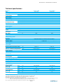
Technical specifications
Model no.
T410-115DU
Type
Control type
Static pressure
Standard
Range
Cooling capacity
Heating capacity
EER for cooling
COP for heating
High
Med.
Low
Outdoor noise level (sound power level)
Indoor noise level at cooling
(sound pressure level)
T410-140DU
Fixed speed
Fixed speed
LCD remote controll and LCD wall controller
50
50
50~180
50~180
36000; 11500
48000; 14000
38000; 12000
50000; 15000
8.78; 2.76
9.89; 2.9
10.9; 3.46
11.8; 3.45
53
53
52
50
51
47
65
68
Pa
Pa
Btu/h;W
Btu/h;W
Btu/h.w; W/W
Btu/h.w; W/W
dB(A)
dB(A)
dB(A)
dB(A)
Electrical data
Power supply
Voltage range
Current
Power input
Cooling
Heating
Cooling
Heating
Max. power
Max. current
220-240V~/50Hz/1P
198~254
18.0
17.4
4150
4000
5865
25.5
V
A
A
W
W
W
A
220-240V~/50Hz/1P
198~254
20.9
18.9
4820
4350
6850
29.8
Refrigerating system
Refrigerant/charge
Evaporator
Condenser
Expansion device
Defrosting system
R410A/3400g
R410A/4000g
Hydrophilic & Louver Fin; Innergroover tube type (φ9.52)
Hydrophilic & Louver or Corrugated Fin; Innergroover tube type (φ7)
Capillary tube
Microcomputer controlled reverse system
Fan system
Outlet size of indoor airflow
Returning vent size of indoor airflow
Indoor air circulation (cooling/heating)
mm
mm
L/S
m3/h
Indoor fan type
Outdoor fan type
855×220
1096×310
695/630/630
2500/2270/2270
Centrifugal
Propeller
855×220
1096×310
750/667/667
2700/2400/2400
Centrifugal
Propeller
Flare
1/2"
3/4"
10
25
5
110
O.D 16
Flare
1/2"
3/4"
10
25
5
110
O.D 16
1200×380×590
950x1255x410
55
112
1410×445×695
1030x1380x440
60
122
1200×380×590
1000×1510×400
58
132
1410×445×695
1135×1645×440
63
145
Connections
Refrigerant coupling
Connecting pipe
Liquid
Gas
Max. height drop (high head)
Max. length of connecting pipe
Max. pipe length with standard charge
Refrigerant charge with long pipe
Drainage pipe
Inches
Inches
m
m
m
g/m
mm
Size and weight
Net dimensions
(W x H x D)
Net weight
Packing dimension
(W x H x D)
Gross weight
Indoor
Outdoor
Indoor
Outdoor
Indoor
Outdoor
Indoor
Outdoor
mm
mm
kg
kg
mm
mm
kg
kg
Note: specifications are based on the following conditions:
Cooling: Indoor temperature 27°C DB/19°C WB, and outdoor temperature 35°C DB/24°C WB
Heating: Indoor temperature 20°C DB/15°C WB, and outdoor temperature 7°C DB/6°C WB
Equivalent piping length: 5m, Level difference: 0m, Voltage: 220V
Sound Level: Indoor unit sound pressure level, measured at a point 1.5m downward from the unit centre
Outdoor unit sound pressure level,measured at a point 1.0m in front of the unit
Due to ongoing product development, specifications are subject to change without prior notice
Page 4
Service Manual • T-series Ducted Air Conditioner
WDOOFRQWUROOHURSHUDWLRQ
ᓔ݇
7
;
$
8(
$+
5
(
7
7$
2
:
+
'2:1
7
1
(
0
+
6
(
5
)
(
5
63(('
(
7
8
1
,
0
02'(
5
8
2
+
+
&
(
7
0,
,:
7
6
$,5',5(&7,21
83
6/((3
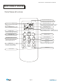
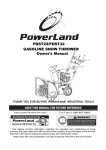
z Button Description˖
1 Power indicator
2 Power on/off
3 Hot water˄Exclusive for double-energy unit˅
4 Aux Heat
5 Up
6 Sleep
7 Down
8 Remote Signal Receiver
9 Minute
10 Timer
11 Hour
12 Mode
13 Fan Speed
14 Air Direction/refreshment
LCD Screen
22
3
4 6 2 5 1 13 16 14
20
19 23
..
&
&(
2
+
/&
&
12
15
21
18
4. Auto
6. Heating 7. Fan speed mark
9. High air speed
17
)
)
2
5
(
0
,
7
7
$
(
+
;
8
$
'
,
0
+
*
,
+
1. DRY 2. Cooling 3. Mode Mark
5. FAN mode
7,0(521
7(03
/2:
7 8 9 24 10 11
5
(
/7
/
8$
):
3 (
0
5
2
70
7
2
6
((
'
1
6
7 <
6
,
1
3 ,
2
(
7
&
( (
/
<
5
,
6
5
'
'
5
7
,
1
$
(
/ : +
0
2 5
26
2
(
,/
5
& $
%)
(
'
27 5
5(
(
7
7$
(
7
8
(+
$3
2
:
$+
6
(
'
2
0
$872
,1'225180%(5
8. Auto Fan Speed
10. Medium air speed
11. Low air speed
12. Wind Direction Mark
13. SLEEP mark
14. Temp Display(invisible)
16. Setting Temp Display
19. TIME
17. LOCK mark
15. SYSTEM mark(reservation)
18. TIMER mark
20. wire controller extension number˄reservation˅
21. Aux Heat Operation Mark
22. Hot Water mode (reservation
24. Refreshment Mark
Page 5
23. Full Water mark
Service Manual • T-series Ducted Air Conditioner
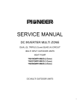
REMOTE CONTROLLER OPERATIONS
Parts of Names & Func tions
Te mpera ture i nd i ca tor
Indicates the sett emper ature.( It doesn'tindicate
tempera ture when oper ation mode is at AUTO)
Tempe ratu re indi c at or
Sy mbols ni d c
i at e OP ERATION MO DE
I ndic at es thes et te mper atu r e.( It d oesn't ind ica te
Indi cat ors for t he ope r ati on wh ich
has bee n s et.
Air flo wind icat or
Indi cat ors the sele ted ai r flo wra te.
temper a tur e when oper a tio n mod e is at AUT O)
AI R FLO W ind ic at o r
In d ic ato r ss ele cte d fla p m od e.
AM
O N/ OFF bu tton
This but ton, whe n pr ess ed,star ts
ope r at ion a nd sto ps wh e n re pr esse d.
Pre se nt t im e a nd ON -TIMER i ndic ator
PM
D urin g O N-T IMERo per at ion. . .. .. [ ST ART ] is indic at ed
D uring nor mal ope ra tio n time. .. . ..t ime o nly is ind ica te d
O N /O F F
FA N S P EED b utt on
Butto nfo r s ettin g the a ir q uantity
AI R FL OW but ton
AI R LO UVER but to n
OP ERATION M O DEs e lectb u t on
This but ton cha nge s flap mod e.
Each tim eth eb utto nis pus hed , the
indic ato r iss witched ove r in turn .
S ET b utto n
Th is b utt ons ets the te mp r atu re and tim e.
MIN .
HR.
TI MER bu tto n
SL EEP bu t ton
Th is b utt on c ha nge s S LEE Po pe r atio n.
The bu t ton se l ec tsO NT I ME R
op er ation o r nor ma l op era t ion.
C LOCK
R ES ET
C LOCK but ton
Page 6
R ESE T b utto n
Service Manual • T-series Ducted Air Conditioner
2SHUDWLRQ'HWDLOV
1.
Safety Protection
(1) Time Delay for Safety protection
z 3 minutes delay for compressor ---The compressor is ceased for 3minutes before
restarting to balance the pressure in the refrigeration cycle in order to protect the
compressor.
z 2 minutes delay for 4-way valve---The 4-way valve will be ceased for 2 minutes late
after compressor to prevent the refrigerant-gas abnormal noise when the HEATING
operation is OFF or switch to the other operation mode.
(2) Discharge temperature protection
There is a temperature sensor on top of compressor, when temperature on top of
compressor exceeded the limit, system control will shut down the compressor and the
display board will show the error code.
(3) lower voltage protection
When AC voltage 158V and keep it for 10 seconds, unit will be shut down for protection.
(4) Over voltage protection
When AC voltage 260V, unit will be shut down and recover while AC255V.
(5) Over current protection
When the current of outdoor unit is overload, controller shut down the unit immediately and
show error code.
(6) Compressor abnormity protection
When compressor start on or in the process of running, if there is no feedback to controller
or load of compressor is abnormity, the air conditioner will shut down, and show error
code.
(7) IPM module protection
IPM module has high temperature & over current protection itself, if there is signal
feedback to IPM, the outdoor unit will shut down, LED on outdoor PCB will show the error
code.
2.
“I Feel” Mode Operation
(1) When the “I Feel” mode is selected, the operation mode and initial temperature set are
determined by the initial room temperature at start-up of the operation except to turn off the
air conditioner and operates it again.
(2) If the mode is change to “I Feel” from other mode, the “I Feel” mode doesn’t operate until
compressor stop for more than 3 minutes.
Mode
Initial Room Temperature
Initial Set Temperature
COOLING
RTı26ć
23ć
DRY
26ć˚RTı20ć
RT-2ć
HEATING for Heat Pump
FAN for Cooling Only
RT˘20ć
-
z
3.
In the “I Feel” mode, when the controller receives the up or down signal of temperature,
the set temperature can adjust by 1ć upper or lower. The biggest you can adjust by
2ć upper or lower.
“COOLING” Mode Operation
Page 7
Service Manual • T-series Ducted Air Conditioner
(1) Compressor frequency control
According to difference room temperature and set temperature(¥t = RT-ST), running
frequency of compressor is controlled by electronic controller. When room temperature is much
higher than set temperature, compressor will start at a high frequency, and as room temperature
goes down, compressor running frequency will go down. When room temperature is lower than set
temperature, compressor will run at very low frequency. In general, unit will change its running
frequency according to¥t to make room temperature closing to set temperature.
(2) Outdoor temperature affects running frequency of compressor
Outdoor temperature affect compressor’s running frequency. Difference inlet temperature of
outdoor unit is adapted by difference compressor running frequency. While outdoor temperature is
about 30ć, the compressor will run in high frequency.
If unit run in “cooling” mode and outdoor temperature is less than -1ćcontroller will shut down
compressor and show error code, while the ambient temperature is over 0ć the compressor will
run automatically
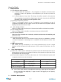
(3) Auto fan control in cooling mode
In cooling mode (include cooling in “I feel” mode), fan speed is determined by ¥t, as the
following diagram:
RT-ST
ć
įt come down
įt come up
high fan
4.
medium fan
low fan
“DRY” Mode Operation
(1) The system for DRY operation used the same refrigerant circle as the cooling one.
(2) When the system operates in DRY mode, at first it operates in cooling mode at 16ć or
18ć for 3 minutes. After that, the system will operate in cooling mode with lowest fan
speed, meanwhile the set temperature (ST) is “RT-2ć” which means that the ST is room
temperature at then minus 2. During the course of this mode, the fan speed set operation
and room temperature set are restricted, except the vane motor adjusting.
5.
“HEATING” Mode Operation (available for Heat Pump only)
(1) Frequency control
The same as the frequency control in cooing mode, running frequency of compressor is
controlled by controller. Unit change its running frequency according to ¥t to make room
temperature closing to the set temperature.
(2) Indoor fan motor control
1. Cold Air Prevention Control
z The function is intended to prevent cold air from being discharged when the heating
operation starts or when defrosting.
z The indoor fan speed will be controlled as following.
Page 8
Service Manual • T-series Ducted Air Conditioner
S
X
H
U
X
W
D
U
H
S
P
H
7
J
Q
L
W
W
H
V
Q
D
I
Z
R
O
ć
H
]
H
H
U
E
ć
S
R
W
V
ć
ć
ć
Q
Z
R
G
H
U
X
W
D
U
H
S
P
H
7
ć
z
In the heating operation, if the air conditioner is turned off, the indoor fan motor will
run most for 30 seconds since the stop of compressor.
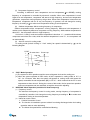
2. Auto fan control (heating)
In heating mode(include in “I feel” mode) , fan speed is determined by ¥t, as the following:
R T -S T
ć
įt com e dow n
įt com e up
h ig h fa n
m id iu m fa n
lo w fa n
(3) 4-way valve control
In heating mode, 4-way valve will power on ahead of compressor for 5 seconds, and cut off
for 2 minutes later than compressor’s stop. 4-way valve will not power off unless the machine is
switched off, mode changed or on the process of defrosting.
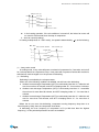
(4) Defrosting
Defrosting is controlled by the microprocessor.
When one of the following conditions is satisfied, unit will come into defrosting:
a. Outdoor heat exchanger Temperature (OPT) is continuously less than 3ć while the unit
runs for more than 40 minutes, and OPT is keeping under -6ć for more than 3 minutes.
b. Outdoor heat exchanger Temperature (OPT) is continuously less than 3ć meanwhile
the unit runs for more than 80 minutes, and OPT is keeping under -4ć for more than 3
minutes.
c. Outdoor heat exchanger Temperature (OPT) is continuously less than 3ć while the unit
runs for more than 120 minutes, and OPT is keeping below -2ć for more than 3
minutes.
Before the air con come into defrosting, compressor running frequency drop down to a
lower frequency firstly, then the compressor shuts down.
In defrosting, the max. frequency of compressor is F9 (a little less than the highest
frequency ). In this period all protection function are avaliable.
Page 9
Service Manual • T-series Ducted Air Conditioner
ON
OFF
ON
4 - w a y v a lv e
OFF
ON
o u td o o r fa n m o to r
OFF
c o m p re s s o r
20s
10s
10m
20s
10s
In defrosting, LED showing by winking.
Come into or out of defrosting, indoor fan motor speed is the same as Cold Air Prevention
Control.
One of the following conditions is satisfied, unit come out of defrosting and shift to heating
mode:
a. Outdoor coil Temperature (OPT) ı15ć
b. Defrost time keep time for more than 10 minutes.
(6) Indoor exchanger overheat protection
When Indoor exchanger Temperature(IPT) is higher than 55 ć , unit come into indoor
exchanger overheat protection. Compressor drop its frequency toward to F1 level until IPTİ52
ć; If IPTİ52ć and keep for 5 minutes , control system don’t limit running frequency.
If IPT>62ć, control system shut down compressor, and recover when IPT drop less than 50ć.
6.
“SLEEP” mode
When the SLEEP button is pressed, the SLEEP mode is selected as following:
z The indoor fan speed is set at low speed, the power lamp and the sleep lamp is on, the
display of temperature will be close after 5 minutes.
z When selecting COOLING/DRY operation with SLEEP mode, the set temperature will be
raised by 1ć 1 hour later and by 2ć 2 hour later.
z When selecting HEATING operation with SLEEP mode, the set temperature will be dropped
by 1ć 1 hour later and 2ć 2hour later.
z After the System operates in SLEEP mode for 8 hours, it will stop automatically.
7.
EMERGENCY Operation
When the EMERGENCY Operation switch is pressed once, COOLING mode is selected and if
in 3 seconds the EMERGENCY Operation switch is pressed again, mode is selected. Then
pressed once again, the unit is switch off.
When the remote controller is missing, has failed or the batteries run down, press the
EMERGENCY Operation switch on the front of the indoor unit. The unit will start.
The first 30 minutes of operation will be the test run operation. The operation is for servicing.
The indoor fan runs at high speed and the system is in continuous operation. The thermostat is
ON and the timer is reset to normal.
After 30 minutes of test run operation the system shifts to AUTO COOLING/HEATING mode,
and the indoor fan runs in automatic speed. The operation continues unit the EMERGENCY
operation switch is pressed or a button on the remote controller is pressed, the normal
operation will start.
NOTE: Do not press the EMERGEMCY Operation switch during normal operation.
8. AUTO-RESTART Function (Option)
1. When air conditioner is operating in one mode, all of its operation data, such as working
mode and temperature of setup would be memorized into IC by main PCB. If power cuts due to
Page 10
Service Manual • T-series Ducted Air Conditioner
some reason, when power supply come back again, the AUTO-RESTART function will set
synchronously and automatically to work. So the air conditioner would work at the same mode
before.
Auto-restart Pre-setting (optional):
If Auto-restart function is needed, follow the steps below to activate this function:
1) Pulling the air-con's plug out of socket.
2) Pressing and holding the Emergency button (ON/OFF) on the indoor, then insert the plug
into the socket again.
3) Keep pressing the Emergency button for more than 10 seconds until three short beeps are
9.
heard. The Auto-restart function has been started.
Protection and Failure Display
z When protection display is available, controller will show error code, digital LED shows
error code and setting temperature by turns.
z If there is more than one failure, it will show at first that in front of the error list.
z Protection display function can be selected in hardware, and the default don’t display;
z To insure of in and out communist is credibility, the failures relate to outdoor unit will
remain failure state for 2 minutes max after recovered.
z In all failures, only sensor failures don’t have to repower to cancel.
Page 11
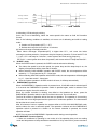
Service Manual • T-series Ducted Air Conditioner
Wiring controller installation
3-bored control pad program and 6-bored control pad program can be
compatible in the wire controller. When dialing code switch SW1 at the back
of wire controller is moved to "NO",
3-bored control pad program is chosen; when it is moved to "OFF", 6-bored
control pad program is chosen.
Noneffective
23(5$7,1*&21752//(5
&1
&1$
21
21
2))
6:
&211(&7,1*&$%/(
6:˖2))
6:˖86(/(66
PCB with 6 Needle Junction
&1
Noneffective
21
21
&211(&7,1*&$%/(
PCB with 3 Needle
Junction
2))
6:
23(5$7,1*&21752//(5
&1$
6:˖21
6:˖86(/(66
Wiring Display Instruction
When any trouble occurs in the electric circuit, LCD display code of trouble,
the relationship of code and trouble can be listed as following:
Priority
Code
Display
Byte
Data2
1
E2
02
Outdoor Protection˄recoverable˅
2
E6
06
Wire controller and control pad communication ( recoverable )
3
E7
07
Room Temp sensor abnormal˄ recoverable ˅
4
E8
08
Condensor sensor abnormal˄ recoverable ˅
5
E9
09
Evaporator sensor abnormal ˄ recoverable ˅
6
EE
0E
EEPROM communication abnormal(recoverable when power
is on again)
Trouble
Page 12
Service Manual • T-series Ducted Air Conditioner
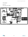
Wiring diagram
Indoor unit
T410-115DU, T410-140DU
Page 13
Service Manual • T-series Ducted Air Conditioner
Wiring diagram
Outdoor unit
T410-115DU, T410-140DU
Page 14
Service Manual • T-series Ducted Air Conditioner
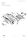
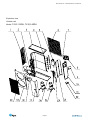
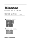
Explosion view
Indoor unit
Model:7'87410-140DU
Page 15
Service Manual • T-series Ducted Air Conditioner
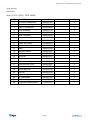
Spare part list
Indoor unit
Model:7'8T410-140DU
NO.
Part Name
Part NO.
Remark
Q'ty
1
air outlet subassembly
3084555108
1
2
air outlet assembly
3084584314
1
3
circle of air director
3084554845
1
4
scroll assembly
3084537112
1
5
fan
3074537101
2
6
scroll fix board
3084535915
1
7
fan motor bracket
3084554835
1
8
fan motor clamp
3084554842
1
9
indoor fan motor
3174555101
1
10
down plate
3084557001
1
11
beam
3084555106
1
12
right side barrier
3084557003
1
13
left side barrier
3084557002
1
14
top cover
3084557011
1
15
electronic box bracket
3084554831
1
16
electric controller box
3084554843
1
17
electronic box cover
3084554867
1
18
fix pipe board
3084554838
1
19
fix drip tray bar
3084555118
1
20
drip tray
3084557010
1
21
drip tray airproof
3084555116
1
22
top crossbeam
3084555101
1
23
left corner knighthead
3084554834
1
24
evaporator subassembly
3114555101
1
Page 16
Service Manual • T-series Ducted Air Conditioner
Explosion view
Outdoor unit
Model: T410-115DU, T410-140DU
Page 17
Service Manual • T-series Ducted Air Conditioner
Spare part list
Outdoor unit
Model: T410-115DU, T410-140DU
NO.
1
2
3
3
4
5
6
7
8
9
10
11
12
13
14
15
16
17
18
19
20
23
24
25
26
27
28
29
30
Part NO.
Material Name
Left protection net
Outdoor Motor
Supproter of Outdoor Motor
Top Cover
Upper Condenser 1 subassembly
Lower Condenser 2 subassembly
Accumulator
Back Net
Electronic control box assembly
Outdoor PCB
Outdoor softstart PCB
Handle
Right plate
3-way Valve (gas valve)
2-way Valve (liquid valve)
Partition plate
Winding of 4-way valve
4-way valve
Compressor
Base subassembly
Right front panel
Outdoor Axial fan
Lift front panel
Air outlet griller
Transformer
AC Contact
Cable clamp( Tcrminal˅
Clamp
Capacitor for compressor
Capacitor for compressor soft start
Capacitor for fan motor
Condenser sensor
Page 18
3212510108
3173010110
3083010127
3082510701
3112600202
3112600201
3120160019
3083010111
3083010137
3092600201
3172512602
3073010103
3212600201
3120130039
3120120014
3212600208
3172510101
3120110001
3100060490
3087010201
3217010112
3070030002
3083010104
3082510124
3171990142
3171990004
3170200005
3071990016
3170100004
3170100031
3170100010
3160130006
Remark
YDK70-6
1510×225×t1.5
I2HC/HO.00-03
ZYG-19
DYF-35 ij19.05
2 3/4 "-16UNF
Not shown in
explosion view
Quantity
1
1
1
1
1
1
1
1
1
1
2
1
1
1
1
1
1
1
2
1
1
1
1
1
1
2
1
1
1
1
1
1