1
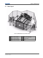
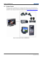
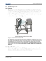
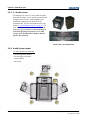
NASA Goddard Flight Dynamics CAVE
User's Manual
020-100049-01 Rev. 1
TABLE OF CONTENTS
1 Introduction
1.1 Reference Documentation................................................................................................1-2
1.1.1 COTS Documentation..............................................................................................1-2
1.1.2 Christie Digital Documentation ...............................................................................1-2
1.2 Document Conventions....................................................................................................1-2
1.3 Technical Support Contact Information ..........................................................................1-3
2 CAVE Overview
2.1 Overview..........................................................................................................................2-2
2.2 Room Layout ...................................................................................................................2-3
2.3 System Control ................................................................................................................2-4
2.4 CAVE Components .........................................................................................................2-5
2.4.1 Projectors .................................................................................................................2-5
Projector Control Panel and Status LED ..................................................................2-5
2.4.2 ChristieTwist™ Basic 1.0 ........................................................................................2-5
2.4.3 5.1 Audio System .....................................................................................................2-6
2.4.4 Audio System Layout...............................................................................................2-6
2.4.5 Control Center..........................................................................................................2-7
2.4.6 AMX Control Panel .................................................................................................2-7
2.4.7 Laptop Interface .......................................................................................................2-7
2.4.8 AV Equipment Rack ................................................................................................2-8
2.4.9 Tracking System ......................................................................................................2-9
2.4.10 Stereo 3D Equipment .............................................................................................2-9
2.4.11 LINKSYS Router ...................................................................................................2-10
3 Control Panel Interface
3.1 Touch Panel Interface ......................................................................................................3-2
3.1.1 Splash Screen ...........................................................................................................3-2
3.1.2 Main Control Panel Overview .................................................................................3-3
3.2 Turn System Devices ON ................................................................................................3-5
3.2.1 Turn Projectors and Audio ON ................................................................................3-5
3.3 Routing Signals................................................................................................................3-6
3.3.1 Routing to OFE Supplied Control Monitor..............................................................3-6
Cluster 0 ....................................................................................................................3-6
Laptop .......................................................................................................................3-6
Tracking PC ..............................................................................................................3-6
3.3.2 Routing to CAVE Display .......................................................................................3-7
3.3.3 Routing Audio Signals to the Audio System ...........................................................3-8
3.4 Setting Up for a Laptop Presentation...............................................................................3-9
3.5 Video Muting ...................................................................................................................3-10
3.5.1 Video Muting via the Main Control Interface .........................................................3-10
3.6 Audio Volume Controls...................................................................................................3-11
3.7 Advanced Controls Interface ...........................................................................................3-12
3.8 Advanced Controls - Projectors .......................................................................................3-13
NASA Goddard Flight Dynamics CAVE User’s Manual
020-100049-01 Rev. 1 (10/07)
i
TABLE OF CONTENTS
3.8.1 Overview ..................................................................................................................3-13
3.8.2 Manually Controlling Projector Power ....................................................................3-14
3.8.3 Manual Video Muting of Projectors ........................................................................3-14
3.8.4 Lamp Status Messages .............................................................................................3-15
Lamp Replacement Procedure ..................................................................................3-15
3.9 Advanced Controls - Video Switching ............................................................................3-16
3.9.1 Overview ..................................................................................................................3-16
3.9.2 Manually Routing Video..........................................................................................3-17
3.10 Advanced Controls - Audio Switching ..........................................................................3-18
3.10.1 Overview ................................................................................................................3-18
3.10.2 Manually Routing Audio .......................................................................................3-19
3.11 Advanced Controls - Receiver Configuration ...............................................................3-20
3.12 System Shutdown Interface ...........................................................................................3-21
3.12.1 Overview ................................................................................................................3-21
3.12.2 Turn Projectors OFF ..............................................................................................3-22
3.12.3 Turn Audio OFF.....................................................................................................3-23
3.12.4 Turn Projectors and Audio OFF.............................................................................3-23
3.12.5 Complete System Shutdown ..................................................................................3-23
3.13 Complete System Power Up and Shutdown Procedures ...............................................3-24
3.13.1 Cold Start ...............................................................................................................3-24
3.13.2 Complete Shutdown...............................................................................................3-24
4 Tracking System
4.1 InterSense 6DOF Tracking System ................................................................................4-2
4.1.1 CDS Service and Tracking PC.................................................................................4-2
4.1.2 IS900 Base Station ...................................................................................................4-2
4.1.3 Tracking Native Origin and Orientation ..................................................................4-2
4.2 About the CDS Tracking and Service PC........................................................................4-3
4.2.1 About the ISDEMO application...............................................................................4-3
4.2.2 Initialize Tracking System .......................................................................................4-3
4.2.3 Working with ISDEMO ...........................................................................................4-4
4.3 About the TrackDServer application ...............................................................................4-6
4.3.1 Initialize TrackDServer............................................................................................4-6
4.4 Direct Matrix Switching ..................................................................................................4-6
Setting the RGB / Audio Matrix for Video ...............................................................4-6
Setting the RGB / Audio Matrix for Audio ..............................................................4-7
4.5 Troubleshooting ...............................................................................................................4-8
4.5.1 Reload Constellation ................................................................................................4-8
Appendix A Serialized Equipment List
A.1 Serialized Equipment List...............................................................................................A-2
NASA Goddard Flight Dynamics CAVE User’s Manual
020-100049-01 Rev. 1 (10/07)
ii
1
Introduction
Every effort has been made to ensure the information in this document is accurate and reliable;
however, due to constant research the information in this document is subject to change without notice.
• Section 1.1 Reference Documentation
• Section 1.2 Document Conventions
• Section 1.3 Technical Support Contact Information
NASA Goddard Flight Dynamics CAVE User’s Manual
020-100049-01 Rev. 1 (10/07)
1-1
Section 1: Introduction
1.1
Reference Documentation
1.1.1 COTS Documentation
•
•
•
•
•
•
•
•
•
•
•
JBL Control® 25AV Shielded Indoor/Outdoor Monitor Speaker Specifications
AMX NI-3100 NetLinx Integrated Controller Quick Start Guide
AMX NXA_AVB / Ethernet Modero Ethernet / Video Breakout Box Quick Start Guide
AMX 10” Modero Widescreen Video Touch Panels (Firmware Version G4) Quick Start Guide
StereoGraphics® EXXR Emitter Setup and Installation Guide
StereoGraphics® Crystal Eyes3 User’s Guide
NTI XTENDEX™ Series USB-C5 USB Extender Installation and User Guide
Extron® Electronics CrossPoint 450 Plus Series MAV Plus Series Matrix Switcher’s User’s Manual
Extron® RGB 109xi Laptop Interface User’s Manual
Denon AV Surround Receiver AVR-2807 Operating Instructions
ASTRO Flexible Scan Converter SC-2040, SC-2040T, SC-2040B, SC-2040W Operating Manual
Ver. 1.08
• Furman 20 AMP Series II Professional Power Conditioners P-8 PRO II / PL-8 PRO II Owner’s
Manual
• LINKSYS® 10/100/1000 Gigabit Switch Business Series
• InterSense IS900 User's Manual
NOTE: Documentation for Christie-supplied, third- party devices is located in the
COTS Documentation file box.
1.1.2 Christie Digital Documentation
• ChristieTwist Ver. 1.0 Installation and User’s Guide (#013-100200)
• Using 3D in Mirage (#013-100195)
• Christie DS+5K/Kc-8K/DW3K-6K/Kc Mirage S+2-4-8K/DLV1400-DX/Matrix 4000 User Manual
(#013-100199)
1.2
Document Conventions
The following text formats are used throughout this manual:
•
•
•
•
•
•
1-2
Content Reference e.g. Section 6 - Specifications
Document Reference e.g. Using 3D in Mirage
Figure/Table References e.g. Figure 2.1, Table 4.3
Software Menus/Options e.g. Main Menu, Preferences
Onscreen Messages e.g. No Signal
OPERATIONAL STATES - POWER, ON, OFF
NASA Goddard Flight Dynamics CAVE User’s Manual
020-100049-01 Rev. 1 (10/07)
Section 1: Introduction
1.3
Technical Support Contact Information
SGI Service and Support
SGI Solutions Serial Number: SOLN0271
SGI Phone Support: SGI is pleased to offer a single point of contact for all issues regarding the
NASA Goddard Flight Dynamics CAVE. For any support issues, please contact the SGI Support
Hotline by calling 1-800-800-4SGI. Have your solutions serial number available when calling.
NASA Goddard Flight Dynamics CAVE User’s Manual
020-100049-01 Rev. 1 (10/07)
1-3
Section 1: Introduction
1-4
NASA Goddard Flight Dynamics CAVE User’s Manual
020-100049-01 Rev. 1 (10/07)
2
CAVE Overview
The following section provides an overview of the components used in the NASA Goddard Flight
Dynamics CAVE.
•
•
•
•
2.1 Overview
2.2 Room Layout
2.3 System Control
2.4 CAVE Components
NASA Goddard Flight Dynamics CAVE User’s Manual
020-100049-01 Rev. 1 (10/07)
2-1
Section 2: CAVE Overview
2.1
Overview
NOTICE
Wear non-marking or cleanroom shoe covers to preserve the floor screen surface.
The NASA Goddard Flight Dynamics CAVE, designed by Christie Digital Systems is a four-channel
cave with a tracking and control system used for flight simulation. The custom designed structure
incorporates mirrors and projector mounts, Mirage S+4K projectors (38-DSP104-x6), four 96” by
128” soft display screens and a rigid 128” by 96” floor screen.
FIGURE 2-1 CAVE OVERVIEW
2-2
NASA Goddard Flight Dynamics CAVE User’s Manual
020-100049-01 Rev. 1 (10/07)
Section 2: CAVE Overview
2.2
Room Layout
FIGURE 2-2 NASA GODDARD FLIGHT DYNAMICS CAVE
A
Mirage S+4K Left Display
D
Mirage S+4K Right Display
B
Mirage S+4K Floor Display
E
Blackout Curtain
C
Mirage S+4K Center Display
F
CAVE
NASA Goddard Flight Dynamics CAVE User’s Manual
020-100049-01 Rev. 1 (10/07)
2-3
Section 2: CAVE Overview
2.3
System Control
The display system is controlled by a 10” touch panel, which allows users to control audio/visual
components in the CAVE. For information on all third-party supplied equipment, refer to the COTS
manuals. For more information on the control interface, refer to Section 3 Control Panel Interface.
FIGURE 2-3 TOUCH PANEL CONTROL FOR CAVE DEVICES
2-4
NASA Goddard Flight Dynamics CAVE User’s Manual
020-100049-01 Rev. 1 (10/07)
Section 2: CAVE Overview
2.4
CAVE Components
2.4.1 Projectors
The display system uses four Mirage S+4K projectors (38-DSP104-06), a 4000 lumens, three chip
DLP™ projector, delivering native SXGA+ resolution with a 1.25:1 fixed lens. For more information,
refer to the standard Christie Mirage S+/HD, DS, DW, DLV User’s Manual (#020-100001-xx). The
projection display is designed with a floor projection facilitated by an overhead custom mount
projector and three wall projections facilitated by three projectors mounted to a rear-projection, singlebounce mirror stand. The combination of projectors creates an enclosed four-sided room with a
resolution of 1400 x 1050 per wall/floor (Figure 2-4).
FIGURE 2-4 PROJECTOR WITH DISPLAY STAND / MIRROR
Projector Control Panel and Status LED
The control panel is located on the back of the projector. In addition to a control panel, each projector
also includes a wireless IR remote control. The LED status window on the control panel indicates ON
when the projector is ON or powering ON. The status window also displays error codes when the
projector is not functioning properly or requires maintenance. For information about error codes and
specific features, refer to the standard Christie Mirage S+/HD, DS, DW, DLV User’s Manual (#020100001-xx).
2.4.2 ChristieTwist™ Basic 1.0
Each projector is equipped with a ChristieTWIST Module to support linearity corrections and fine
alignment of the projector display, via the ChristieTWIST software. For more information, refer to
ChristieTwist Ver 1.0 Installation and User’s Guide (P/N 013-100200).
NASA Goddard Flight Dynamics CAVE User’s Manual
020-100049-01 Rev. 1 (10/07)
2-5
Section 2: CAVE Overview
2.4.3 5.1 Audio System
The amplifier can run in 5.1 native mode for audio
connected from host 16 or in pseudo surround sound
for laptop stereo sources. Audio amplifiers and
distribution equipment are housed in the AV
equipment rack. For more information on the rack,
refer to 2.4.8 AV Equipment Rack, on page 2-8. For
more information on the audio system, refer to the
third-party supplied Denon AV Surround Receiver
AVR-2807 Operating Instructions and the JBL
Control 25AV Shielded Indoor/Outdoor Monitor
Speaker Specifications.
FIGURE 2-5 5.1 AUDIO EQUIPMENT
2.4.4 Audio System Layout
5.1 audio includes the following:
• left and right front speaker
• left and right rear speaker
• center channel
• subwoofer
FIGURE 2-6 CAVE AUDIO SYSTEM LAYOUT
2-6
NASA Goddard Flight Dynamics CAVE User’s Manual
020-100049-01 Rev. 1 (10/07)
Section 2: CAVE Overview
2.4.5 Control Center
The control center provides a single control position for
the CAVE equipment. It consists of an AV equipment
rack, a CRT monitor, a laptop connection, a wired
keyboard and mouse, an A/B keyboard/mouse switch
and stereo 3D equipment (i.e., wired stereo glasses). An
NTI xtender is used to extend the keyboard/mouse from
the customer supplied IG to the control center. For more
information, refer to the third-party supplied NTI
XTENDEX Series USB-C5 USB Extender Installation
and User Guide.
FIGURE 2-7 CONTROL CENTER
2.4.6 AMX Control Panel
The CAVE display is controlled by a 10” touch panel which
allows users to control the projection display, the sound system
and the tracking system. For more information, refer to the thirdparty supplied AMX 10” Modero Widescreen Video Touch
Panels (Firmware Version G4) Quick Start Guide.
FIGURE 2-8 TOUCHSCREEN PANEL
2.4.7 Laptop Interface
The laptop interface includes video, network and stereo audio connections. The video connection is
connected to a signal processor, which will scale any input resolution to 1400x1050 @60Hz (i.e., the
projector’s native resolution). This signal processor provides the user the freedom to connect any
laptop source from any VGA compatible laptop computer and display it on the projector without
complicated individual signal setup routines on the projector itself. The laptop is scaled by an Astro
Scan Converter. If the output is incorrect, refer to the third-party supplied Astro Flexible Scan
Converter Operating Manual.
A
Video (HD15/F)
B
Audio
C
Network (CNE NET)
D
Network (AV NET)
FIGURE 2-9 LAPTOP CONFIGURATION
NASA Goddard Flight Dynamics CAVE User’s Manual
020-100049-01 Rev. 1 (10/07)
2-7
Section 2: CAVE Overview
2.4.8 AV Equipment Rack
The AV rack houses the equipment provided by Christie
Digital System Inc. The rack includes an 8x8 highbandwidth video matrix switch, which supports 8 inputs
and 8 output channels. The 8x8 matrix routes the 4 video
channels from the customer supplied IG to the four
projectors and control monitor. Currently, 6 inputs and
five outputs are populated; therefore, there are 6 possible
sources available to 5 destinations. Additional inputs
include the laptop and a low-resolution AV signal from
the AV receiver. This matrix also supports the required
audio switching. All power for the rack goes through the
Furman. For more information, refer to the third-party
supplied Furman 20 AMP Series II Professional Power
Conditioners Owner’s Manual.
NOTE: The Extron 8x8 switch is housed in the 12 x 8
class housing. 4 buttons are not connected.
FIGURE 2-10 AV EQUIPMENT RACK
2-8
NASA Goddard Flight Dynamics CAVE User’s Manual
020-100049-01 Rev. 1 (10/07)
Section 2: CAVE Overview
2.4.9 Tracking System
A 6° of freedom wireless motion tracking system is installed to support computer applications that use
a head and wand motion tracking. The tracking system uses hybrid technology with gyroscopically
corrected inertial sensors and an ultra-sonic reference grid. For more information, refer to Section 4
Tracking System and the InterSense IS900 User’s Manual.
FIGURE 2-11 INTERSENSE TRACKING SYSTEM
2.4.10 Stereo 3D Equipment
CAUTION
To avoid stepping on the wires when using the wand it is good practice to hold the
cables in your opposite hand to manage the wired tracker cabling.
An array of StereoGraphics EXXR Emitters enable full infrared coverage to facilitate stereoscopic 3D
visualization. Ten pairs of active stereo glasses (9 wireless/1 wired) are included. The tracking system
wand is wired to the AV rack and the head tracker is attached to a pair of stereo glasses. For
information about the stereo 3D equipment, refer to the third-party StereoGraphics EXXR Emitter
Setup and Installation Guide and the StereoGraphics Crystal Eyes3 User’s Guide.
FIGURE 2-12 CRYSTAL EYES/EMITTER AND TRACKING SYSTEM WAND
NASA Goddard Flight Dynamics CAVE User’s Manual
020-100049-01 Rev. 1 (10/07)
2-9
Section 2: CAVE Overview
2.4.11 LINKSYS Router
LinkSys is connected to the A/V network only. Design of the network topology is covered in the
as-built design schematics. For more information, refer to the third-party supplied LINKSYS 10/100/
1000 Gigabit Switch Business Series documentation.
Table 2.1 Network Interfaces
Description
IP Address
Subnet
Gateway
Projector 1
192.168.1.1
255.255.255.0
Default
Projector 2
192.168.1.2
255.255.255.0
Default
Projector 3
192.168.1.3
255.255.255.0
Default
Projector 4
192.168.1.4
255.255.255.0
Default
AMX Control System
192.168.1.5
255.255.255.0
Default
AMX Touch Panel
192.168.1.6
255.255.255.0
Default
Tracking PC
192.168.1.7
255.255.255.0
Default
InterSense Base Station (IS900)
192.168.1.8
255.255.255.0
Default
*IG Node 1
192.168.1.11
255.255.255.0
Default
*IG Node 2
192.168.1.12
255.255.255.0
Default
*IG Node 3
192.168.1.13
255.255.255.0
Default
Laptop Interface
192.168.1.15
255.255.255.0
Default
*IG exists on A/V network and node 1 is bridged to NASA LAN internally by client.
2-10
NASA Goddard Flight Dynamics CAVE User’s Manual
020-100049-01 Rev. 1 (10/07)
3
Control Panel Interface
This section provides an overview of the interface and outlines the features and selections
available to the user.
•
•
•
•
•
•
•
•
•
•
•
•
•
Section 3.1 Touch Panel Interface
Section 3.2 Turn System Devices ON
Section 3.3 Routing Signals
Section 3.4 Setting Up for a Laptop Presentation
Section 3.5 Video Muting
Section 3.6 Audio Volume Controls
Section 3.7 Advanced Controls Interface
Section 3.8 Advanced Controls - Projectors
Section 3.9 Advanced Controls - Video Switching
Section 3.10 Advanced Controls - Audio Switching
Section 3.11 Advanced Controls - Receiver Configuration
Section 3.12 System Shutdown Interface
Section 3.13 Complete System Power Up and Shutdown Procedures
NASA Goddard Flight Dynamics CAVE User’s Manual
020-100049-01 Rev. 1 (10/07)
3-1
Section 3: Control Panel Interface
3.1
Touch Panel Interface
3.1.1 Splash Screen
The Splash Screen appears on the touch panel at startup and when the system is shutdown. To access
the Main Control Interface touch anywhere on the screen.
FIGURE 3-1 SPLASH SCREEN
3-2
NASA Goddard Flight Dynamics CAVE User’s Manual
020-100049-01 Rev. 1 (10/07)
Section 3: Control Panel Interface
3.1.2 Main Control Panel Overview
The control panel for the NASA Goddard Flight Dynamics CAVE has a touch sensitive screen. To
make a selection, simply touch the desired button on the touchscreen - active sources are displayed
with a green button (inactive buttons are blue). The interface provides users with visual feedback of the
current selected video source and audio system, as well as current projector status. Figure 3-2
illustrates the features of the Main Control Interface. The contents under Control Monitor are always
available. The availability of the contents under Projection Display, Audio and Volume varies
depending on CAVE status. The Projector Status section of the interface provides the user with the
current state of the four projection displays.
FIGURE 3-2 FLIGHT DYNAMICS CAVE INTERFACE
A
Control Monitor Selections
E
Projector Status Display
B
Advanced Controls Touchscreen Button
F
Audio Selections
C
Shutdown Touchscreen Button
G
Volume Controls
D
Projection Display Selections
Overview
Control Monitor: This section of the interface enables users to route a specific source to the control
monitor at the CAVE, regardless of the state of the audio and projectors.
• Cluster 0: Select Cluster 0 to route this display source to the control monitor. Clusters 1 through 3
can only be manually routed to the control monitor using the Advanced Controls settings. For more
information, refer to Section 3.9 Advanced Controls - Video Switching.
• Laptop: Select Laptop to route this display source to the control monitor.
• Tracking PC: Select Tracking PC to route this display source to the control monitor.
Projection Display: This section of the interface enables users to select from the three main sources,
which are used to route the selected video to the CAVE.
NASA Goddard Flight Dynamics CAVE User’s Manual
020-100049-01 Rev. 1 (10/07)
3-3
Section 3: Control Panel Interface
• PC Cluster: Press this touchscreen button to display the graphic nodes on the CAVE walls that they
are by default assigned to.
• Laptop: Press this touchscreen button to display the auxiliary source connected to the laptop on the
front wall (full screen).
• Tracking PC: Press this touchscreen button to display the rackmount tracking PC on the front wall
(full screen).
• Mute Image: Press this touchscreen button to place all four projectors in STAND-BY mode. To
unmute the image press the touchscreen button a second time or select/re-select a preset to unmute
the image and route the selected video to the CAVE.
Projector Status: This section of the interface shows the current state of the projectors.
The five states of operation are:
• OFF: When the entire system is powered down the projector status indicators (left, center, right,
floor) will read OFF. In this state the Projection Display selections remain available to select. To
power up the CAVE select from one of the three Projection Display selections (i.e., PC Cluster).
• ON: Once a selection is made from the Projection Display options (i.e., PC Cluster) the projectors
are initialized. A five second elapse time is required for a signal to be routed to the projectors. After
the time has elapsed the selected preset configuration is routed to the CAVE.
• Warming Up: Once the configuration is routed the projector status indicators will display the status
message, Warming Up. Do not adjust the projectors during warm up. The projectors require five
minutes to warm up to their full operational state. The projectors have been optimized for this
particular application and should not require any adjustments.
• Image Muted: This status message appears when the image to the particular projection display is
muted. To mute all projectors activate the Mute Image touchscreen button from the Projection
Display selections. To mute individual selections access the advanced projector controls. For more
information, refer to Section 3.8 Advanced Controls - Projectors.
• Cooling Down: When the projectors are turned OFF via the System Shutdown Interface the status
message, Cooling Down appears and the Projection Display selections are grayed-out for
approximately five minutes. This wait time ensures the projectors cool down completely. Once the
cool down is complete the Projection Display selections are available again and the projector status
indicators display the status message, OFF. At this point the projectors can be powered up again.
Audio: This section of the interface enables users to control audio power and route the selected source
to the speakers.
• PC Cluster: Press this touchscreen button to route the PC Cluster to the audio system.
• Laptop: Press this touchscreen button to route the laptop to the audio system.
Volume: Use the designated arrow and Mute touchscreen buttons to control the volume of the audio
system. These functions are only available when an audio source is selected, otherwise they are
grayed-out.
Advanced Controls: Press this touchscreen button to access the Advanced Controls Interface. For
more information, refer to Section 3.7 Advanced Controls Interface.
Shutdown: Press this touchscreen button to access the Shutdown Controls Interface. For more
information, refer to Section 3.12 System Shutdown Interface.
3-4
NASA Goddard Flight Dynamics CAVE User’s Manual
020-100049-01 Rev. 1 (10/07)
Section 3: Control Panel Interface
3.2
Turn System Devices ON
For information on how to cold start the system, refer to Section 3.13 Complete System Power Up and
Shutdown Procedures.
3.2.1 Turn Projectors and Audio ON
1. Touch anywhere on the Splash Screen to access the Main Control Interface.
2. Activate any of the Projection Display preset touchscreen buttons (Figure 3-3) to turn the
projectors ON and route the requested preset configuration to the CAVE display.
3. Projector Status displays the message, Warming Up during the initial power up sequence. It
takes approximately 5 minutes for the projectors to reach full brightness and stability after being
powered ON. Once the warm up sequence is complete the status messages will change to ON. Do
not make adjustments to the projected images until the projectors are properly warmed up.
4. Activate any of the Audio preset touchscreen buttons (Figure 3-3) to turn the amplifier ON and
route the selected audio source. Use the volume controls to adjust sound levels.
FIGURE 3-3 MAIN CONTROL INTERFACE
NASA Goddard Flight Dynamics CAVE User’s Manual
020-100049-01 Rev. 1 (10/07)
3-5
Section 3: Control Panel Interface
3.3
Routing Signals
3.3.1 Routing to OFE Supplied Control Monitor
Users are able to route any of the three display sources (Cluster 0, Laptop and Tracking PC) to the
control monitor at the CAVE regardless of audio and projector state. For information on the advanced
routing features of this interface, refer to 3.9 Advanced Controls - Video Switching.
Cluster 0
Cluster 0 represents the first graphics output of the NASA cluster and left wall of the CAVE. The
visual component of the NASA cluster is comprised of four graphics nodes, split across two CPU
nodes. A third CPU node serves as IG Master and is not connected to the CAVE display.
Activate the Cluster 0 touchscreen button from the Main Control Interface to select the main CAVE
PC. Once touched, the Cluster 0 video will route to the control monitor and users can view the video
or control the cluster. The master (Cluster 0) is the only IG node that can be routed from the Main
Control Interface to the control monitor. The other cluster video inputs can be routed to the control
monitor via the Advanced Controls Interface.
Laptop
Activate the Laptop touchscreen button from the Main Control Interface to view the video from the
laptop interface, which is typically used to display presentations onto the CAVE. When routing the
laptop ensure it is plugged into the Extron laptop interface and that the laptop is configured to export
video. For more information, refer to 2.4.7 Laptop Interface.
Tracking PC
This stand-alone PC can be found at the bottom of the AV equipment rack. The Tracking PC takes info
from the tracker over a serial connection and formats the tracking data to match the display volume.
This data is then sent to the visual cluster via Ethernet where a software daemon reads the data and
makes it available for the application running or the cluster. It is useful to view video from the
Tracking PC to debug the tracking system using the IS900 software or TrackDServer. Activate the
Tracking PC touchscreen button from the Main Control Interface to view video from the Tracking PC.
For more information on the tracking system, refer to Section 4 Tracking System.
FIGURE 3-4 ROUTING TO CONTROL MONITOR
3-6
NASA Goddard Flight Dynamics CAVE User’s Manual
020-100049-01 Rev. 1 (10/07)
Section 3: Control Panel Interface
3.3.2 Routing to CAVE Display
The following procedure shows how to control the CAVE via Cluster 0 and how to project to the
display via PC Cluster.
1. Activate the Cluster 0 touchscreen button from the Control Monitor selections to control the
display via Cluster 0 of the PC Cluster.
2. From the Projection Display selections, activate the PC Cluster touchscreen button to route the
PC Cluster (Cluster 0, 1, 2 and 3) to the CAVE. When this touchscreen button is activated the
projectors are powered ON, the appropriate channel is selected and the video is routed to the
projector via the equipment rack.
NOTE: When selecting Laptop from the Projection Display all projectors are muted by default. Users
must go to the Advanced Controls Interface and manually unmute each projector. When PC Cluster is
selected all projectors are ON by default.
3. If not already ON, the Projector Status displays the message, Warming Up during the initial
power up sequence. It takes approximately five minutes for the projectors to reach full brightness
and stability after being powered ON. Once the projector warm up sequence is complete the status
messages will change to ON.
FIGURE 3-5 ROUTING TO CAVE DISPLAY
NASA Goddard Flight Dynamics CAVE User’s Manual
020-100049-01 Rev. 1 (10/07)
3-7
Section 3: Control Panel Interface
3.3.3 Routing Audio Signals to the Audio System
The audio system supports direct 5.1 surround sound and simulated surround for traditional stereo
input. On the Main Control Interface, when switching the audio sources, the Denon amplifier mode is
automatically switched. For information on advanced audio features, refer to 3.10.2 Manually Routing
Audio, on page 3-19.
1. Ensure the Denon audio receiver is powered ON.
2. If the audio system is OFF, activating either the Laptop or PC Cluster touchscreen buttons will
turn audio ON and route the selected source to the speakers.
3. If the audio system is ON pressing a source will re-direct the audio to the selected source.
4. Use the Mute touchscreen button and designated arrow keys to control volume.
FIGURE 3-6 ROUTING AUDIO
3-8
NASA Goddard Flight Dynamics CAVE User’s Manual
020-100049-01 Rev. 1 (10/07)
Section 3: Control Panel Interface
3.4
Setting Up for a Laptop Presentation
1. Ensure the laptop is connected to the Extron laptop interface. For details, refer to Laptop Interface
on page 2-7.
2. Activate the Laptop touchscreen button from the Control Monitor selections to route to the OFE
supplied control monitor. This will enable the user to view the laptop on the control monitor.
NOTE: Press Cluster 0 or Tracking PC to re-route the selected source to the OFE supplied monitor.
3. Activate the Laptop touchscreen button from the Projection Display selections to route the
projected display from the laptop. Once activated all the projectors shutter (i.e., all videos are
muted) except for the front wall.
NOTE: Press PC Cluster or Tracking PC to re-direct the CAVE display to the selected source.
FIGURE 3-7 PRESENTATION SETUP
NASA Goddard Flight Dynamics CAVE User’s Manual
020-100049-01 Rev. 1 (10/07)
3-9
Section 3: Control Panel Interface
3.5
Video Muting
3.5.1 Video Muting via the Main Control Interface
The CAVE display can be automatically muted from the Main Control Interface. Video muting does
not turn the projectors OFF; instead a blank image is projected and the projector shutter closes to block
stray light. The advantage of video mute is that it places the projector in a ‘low power consumption’
mode, while keeping the lamp lit. Because turning the lamp ON and OFF effects lamp life it is
suggested that video muting is used when the projectors are not used for a short period of time (i.e.,
lunch breaks, meetings, etc.). Video muting has no affect on audio. In order to video mute individual
projectors users must access the Advanced Controls Interface; however, video muting is automated
through the Main Control Interface. For more information, refer to 3.8.3 Manual Video Muting of
Projectors, on page 3-14.
1. Activate the Mute Image touchscreen button from the Main Control Interface.
2. Once activated, Projector Status displays the message Image Muted and the Mute Image
touchscreen button text changes to Image Muted. Note that whichever signal is routed remains
active even when the images are muted.
3. To unmute the display either activate the Image Muted touchscreen button or select from the
preset projection display configurations to re-route the image.
NOTE: The reason for having image status displayed on the touchscreen button and the Projector
Status display is due both in part to the projector Image Mute override touchscreen buttons available
via the Advanced Controls and to provide feedback when a user is running a single display preset,
such as a laptop.
FIGURE 3-8 MAIN CONTROL INTERFACE - IMAGE MUTED
3-10
NASA Goddard Flight Dynamics CAVE User’s Manual
020-100049-01 Rev. 1 (10/07)
Section 3: Control Panel Interface
3.6
Audio Volume Controls
Use the designated touchscreen arrow keys and the Mute touchscreen button to control audio volume
levels. The bar displays the current volume level.
FIGURE 3-9 VOLUME CONTROL
NASA Goddard Flight Dynamics CAVE User’s Manual
020-100049-01 Rev. 1 (10/07)
3-11
Section 3: Control Panel Interface
3.7
Advanced Controls Interface
To access the Advanced Controls Interface press the Advanced Controls touchscreen button from the
Main Control Interface. This interface allows for advanced control over the system. Independent
control over projectors, video switching and audio switching overrides are available through this
interface. Press the Return touchscreen button at anytime to return to the Main Control Interface.
NOTE: By default the last screen that was viewed appears when users access the Advanced Controls
Interface.
FIGURE 3-10 ADVANCED CONTROLS INTERFACE
Options
• Projectors: Press this touchscreen button to access the advanced projector settings. For more
information, refer to Section 3.8 Advanced Controls - Projectors.
• Video Switching: Press this touchscreen button to access the advanced video switching settings. For
more information, refer to Section 3.9 Advanced Controls - Video Switching.
• Audio Switching: Press this touchscreen button to access the advanced audio switching settings. For
more information, refer to Section 3.10 Advanced Controls - Audio Switching.
• Receiver Config: Press this touchscreen button to access the advanced receiver configuration
settings. For more information, refer to Section 3.11 Advanced Controls - Receiver Configuration.
• Return: Press this touchscreen button to return to the Main Control Interface.
3-12
NASA Goddard Flight Dynamics CAVE User’s Manual
020-100049-01 Rev. 1 (10/07)
Section 3: Control Panel Interface
3.8
Advanced Controls - Projectors
3.8.1 Overview
This interface enables users to control each projector independently and is a useful tool when servicing
the CAVE or customizing configurations. Any changes made here are directly reflected on the Main
Control Interface under Projector Status.
FIGURE 3-11 ADVANCED PROJECTOR CONTROL SETTINGS
Options
Left/Center/Right/Floor Display: Each of the four specific displays can be individually controlled
from the designated menus.
• Power: Press this touchscreen button to power ON the specific projector display. The touchscreen
button turns green when activated.
• Mute: Press this touchscreen button to mute the image from a specific projector display. The
touchscreen button turns green when activated and the text changes to Image Muted.
Lamp Hours: This field displays the number of hours remaining before lamp replacement is required.
Lamp hours starts at 0 and counts up to 900, at which point the onscreen message, Order Lamp
briefly appears. If this is not addressed before lamp hours reaches between 900-1300 the onscreen
value begins flashing and the warning message, Replace Lamp appears. It is highly recommended
all lamps be replaced at the same time. For more information on lamp replacement, refer to
Lamp Replacement Procedure, on page 3-15.
Important! Using the lamp beyond its warranted life is not recommended. It can lead to reliability
problems, poor performance or sudden lamp expiry.
Serial Number: This field displays the serial number assigned to the projector.
Return: Press this touchscreen button to return to the Main Control Interface.
NASA Goddard Flight Dynamics CAVE User’s Manual
020-100049-01 Rev. 1 (10/07)
3-13
Section 3: Control Panel Interface
3.8.2 Manually Controlling Projector Power
To control power to each of the individual displays:
1. Activate the Advanced Controls touchscreen button from the Main Control Interface to access the
Advanced Controls Interface.
2. Activate the Projectors touchscreen button from the Control selections.
3. Press the Power touchscreen button from any of the four screen menus for the left, center, right
and floor display to disable power to the particular display. Once activated the touchscreen button
color changes to green. Projector Status on the Main Control Interface displays the status
message, Cooling Down and the selections in the Projection Display are grayed-out for
approximately 5 minutes. This wait time ensures the projectors cool down completely.
4. Once the cool down is complete the Projection Display selections are available again and
Projector Status displays the message, OFF. At this point the projectors can be powered up again.
To turn the power back ON simply activate the Power touchscreen button again. Once the
configuration is routed the Projectors Status indicators will display the status message, Warming
Up. Do not adjust the projectors during warm up. The projectors require 5 minutes to warm up to
their full operational state.
3.8.3 Manual Video Muting of Projectors
Through the Advanced Controls Interface users are able to individually mute video of each projector.
Press the Mute touchscreen button from any of the 4 screen menus for the left, center, right and floor
display.
1. Activate the Advanced Controls touchscreen button from the Main Control Interface to access the
Advanced Controls Interface.
2. Activate the Projectors touchscreen button from the Control selections.
3. Press the Mute touchscreen button from any of the four screen menus for the left, center, right and
floor display to mute the particular display. Once activated the touchscreen button color changes to
green and the specific Projector Status indicator on the Main Control Interface displays the status
message, Image Muted.
3-14
NASA Goddard Flight Dynamics CAVE User’s Manual
020-100049-01 Rev. 1 (10/07)
Section 3: Control Panel Interface
3.8.4 Lamp Status Messages
Lamp Hours: This field displays the number of hours remaining before lamp replacement is required.
Lamp Hours begins at 0 and counts up to 900, at which point the onscreen message, Order Lamp
briefly appears. If this is not addressed before lamp hours reaches between 900-1300 the onscreen
value begins flashing and the warning message, Replace Lamp appears.
Important! Using the lamp beyond its warranted life is not recommended. It can lead to reliability
problems, poor performance or sudden lamp expiry.
FIGURE 3-12 ADVANCED CONTROLS - PROJECTOR LAMP HOURS
Lamp Replacement Procedure
When a lamp needs to be replaced, it is highly recommended all lamps in the display system be
replaced at the same time.
When replacing a lamp ensure the following tasks are completed:
• reset lamp counter
• change over the lamp to match all lamps
• adjust projector colors
For information on lamp replacement and the associated tasks, refer to the standard manual supplied
with the projector or the lamp replacement procedure included in the new lamp packaging.
NASA Goddard Flight Dynamics CAVE User’s Manual
020-100049-01 Rev. 1 (10/07)
3-15
Section 3: Control Panel Interface
3.9
Advanced Controls - Video Switching
3.9.1 Overview
This interface enables users to route any of the eight video input sources to any of the eight potential
output sources. This is useful when wanting to route any cluster graphics channel to the control
monitor or when debugging the CAVE.
If an output is accidentally activated it cannot be deactivated by simply clicking on the touchscreen
button again. For example, if the Right Projector was routed to Cluster 0 users cannot click on the
Right Projector touchscreen button to deselect it. In order to deactivate the output users must re-route
it to another input. For example, press Cluster 1.0 and then Right Projector. When you return to
Cluster 0 the output Right Projector is no longer assigned.
NOTE: By default the last screen that was viewed appears when users access the Advanced Controls
Interface.
FIGURE 3-13 VIDEO SWITCHING ADVANCED SETTINGS
Options
Inputs
• Cluster 0 - Cluster 3: Select from these inputs to route the designated cluster to a specific output(s).
• Laptop: Select this onscreen button when you want to route the laptop to a specific output(s).
• Tracking PC: Select this onscreen button when you want to route the tracking PC to a specific
output(s).
• Inputs 7 and 8: These selections are provided for future use should the user wish to route additional
equipment.
3-16
NASA Goddard Flight Dynamics CAVE User’s Manual
020-100049-01 Rev. 1 (10/07)
Section 3: Control Panel Interface
Outputs
• Left Projector: Select this onscreen button to route the selected input to the left projector.
• Center Projector: Select this onscreen button to route the selected input to the center projector.
• Right Projector: Select this onscreen button to route the selected input to the right projector.
• Floor Projector: Select this onscreen button to route the selected input to the floor projector.
• Control Monitor: Select this onscreen button to route the selected input to the control monitor.
• Outputs 6-8: These onscreen selections are provided for future use should the user wish to route
additional equipment.
3.9.2 Manually Routing Video
This interface enables users to route any of the eight video input sources to any of the eight potential
output sources. This feature is useful when a developer wishes to route any of the cluster graphics
channels to the control monitor, or during a debugging exercise (e.g., route the tracking PC to the left
display in the CAVE).
The following procedure demonstrates how to route Cluster 1 to the right projector:
1. From the Advanced Controls Interface activate the Video Switching touchscreen button.
2. Select which input to route by activating one of the eight touchscreen buttons from the top screen
selections (Figure 3-13). For example, to route Cluster 1 activate the designated touchscreen
button. The button turns green when activated.
NOTE: Input 8 is not populated to allow the user to route additional equipment, as required.
3. Select which output to route the selected input to by activating one of the eight touchscreen buttons
from the bottom screen selection. For example, to route Cluster 1 to the right projector activate the
designated touchscreen button. The button turns green when activated.
NOTE: Outputs 6 to 8 are not populated to allow the user to add additional equipment, as required.
4. If an output is accidentally activated it cannot be deactivated by simply clicking on the touchscreen
button again. For example, if the Right Projector was routed to Cluster 0 users cannot click on
the Right Projector touchscreen button to deselect it. In order to deactivate the output users must
re-route it to another input. For example, press Cluster 1 and then Right Projector. When you
return to Cluster 0 the output Right Projector is no longer assigned.
NASA Goddard Flight Dynamics CAVE User’s Manual
020-100049-01 Rev. 1 (10/07)
3-17
Section 3: Control Panel Interface
3.10 Advanced Controls - Audio Switching
3.10.1 Overview
This interface enables users to route any audio source(s) to the available outputs.
FIGURE 3-14 AUTO SWITCHING ADVANCED CONTROLS
Options
Inputs
• Cluster Front L/R: Select this onscreen button to route the front left/right speakers to a specific
output(s).
• Cluster Center/Sub: Select this onscreen button to route the center subwoofer to a specific
output(s).
• Cluster Rear L/R: Select this onscreen button to route the rear left/right speakers to a specific
output(s).
• Input 4: This onscreen selection is provided for future use should the user wish to route additional
audio equipment.
• Laptop: Select this onscreen button to route the laptop to a specific output(s). Selecting Laptop
automatically switches both the Audio Matrix Switch and the Audio Receiver to support simulated
surround sound for stereophonic inputs connected to the laptop interface.
• Inputs 6 to 8: These onscreen selections are provided for future use should the user wish to route
additional audio equipment.
Outputs
• Receiver Front L/R: Select this touchscreen button to route the selected input to the front left/right
receiver.
• Receiver Center/Sub: Select this onscreen button to route the selected input to the center/sub
receiver.
• Receiver Rear L/R: Select this onscreen button to route the selected input to the rear left/right
receiver.
3-18
NASA Goddard Flight Dynamics CAVE User’s Manual
020-100049-01 Rev. 1 (10/07)
Section 3: Control Panel Interface
• Simulated Surround: Select this onscreen button to route the selected input to the simulated
surround sound system.
• Outputs 5-8: These onscreen selections are provided for future use should the user wish to route
additional audio equipment
Amp Mode: Native 5.1 Surround: Activate this touchscreen button to select 5.1 surround sound amp
mode.
Amp Mode: Simulated Sound: Activate this touchscreen button to select simulated surround sound
amp mode.
Return: Press this touchscreen button to return to the Main Control Interface.
3.10.2 Manually Routing Audio
The advanced audio feature enables users to route any audio source(s) to any of the 8 output sources.
This feature is useful when a developer wishes to route any of the cluster graphics channels to the
control monitor, or when a debugging exercise is required (e.g., route the tracking PC to the left
display in the CAVE).
NOTE: Selecting ‘Laptop’ automatically switches both the Audio Matrix Switch and the Audio
Receiver to support simulated surround sound for stereophonic inputs connected to the laptop
interface.
The following procedure demonstrates how to route the center speaker and subwoofer to the front left/
right receiver:
1. From the Advanced Controls Interface activate the Audio Switching touchscreen button (Figure
3-14).
2. Select which input to route by activating one of the 8 touchscreen buttons from the top screen
selection (Figure 3-14). For example, to route Cluster 1 activate the designated touchscreen
button. The button turns green when activated.
NOTE: Inputs 4, 6, 7 and 8 are not populated to allow the user to route additional equipment, as
required.
3. Select which output to route the selected input to by activating one of the 8 touchscreen buttons
from the bottom screen selection. For example, to route Cluster 1 to the right projector activate the
designated touchscreen button. The button turns green when activated.
NOTE: Outputs 6 to 8 are not populated to allow the user to add additional equipment, as required.
If an output is accidentally activated it cannot be deactivated by simply clicking on the touchscreen
button again. For example, if Cluster Center/Sub was routed to Receiver Rear L/R users cannot
click on the Receiver Rear L/R touchscreen button to deselect it. In order to deactivate the output
users must re-route it to another input. For example, press Cluster Front L/R and then Receiver Rear
L/R. When you return to Cluster Center/Sub the output Receiver Rear L/R is no longer assigned.
4. Select the Amp Mode: Native 5.1 Surround touchscreen button to select 5.1 surround sound amp
mode.
Or:
5. Select the Amp Mode: Simulated Sound touchscreen button to select simulated surround sound
amp mode.
NASA Goddard Flight Dynamics CAVE User’s Manual
020-100049-01 Rev. 1 (10/07)
3-19
Section 3: Control Panel Interface
3.11 Advanced Controls - Receiver Configuration
This interface is used to troubleshoot and control the Denon audio receiver system. All audio receiver
settings are programmed on-site during installation and should not need to be reconfigured. Press
Menu to access the menu options and use the arrow buttons to shuttle through the menus. Press Enter
to jump to the next menu option. For more information, refer to the third-party Denon AV Surround
Receiver AVR-2807 Operating Instructions.
FIGURE 3-15 ADVANCED CONTROLS - RECEIVER CONFIGURATION
3-20
NASA Goddard Flight Dynamics CAVE User’s Manual
020-100049-01 Rev. 1 (10/07)
Section 3: Control Panel Interface
3.12 System Shutdown Interface
3.12.1 Overview
This interface is accessed by selecting Shutdown from the Main Control Interface. It enables users to
shutdown the entire system, or the projectors and audio individually.
FIGURE 3-16 SYSTEM SHUTDOWN INTERFACE
Options
Projectors OFF: Press this touchscreen button to turn the projectors OFF and continue to work on the
system. For more information, refer to 3.12.2 Turn Projectors OFF, on page 3-22.
Audio OFF: Press this touchscreen button to turn the amplifier OFF. For more information, refer to
3.12.3 Turn Audio OFF, on page 3-23.
All OFF: Press this touchscreen button to shutdown the projectors and audio equipment. For more
information, refer to 3.12.4 Turn Projectors and Audio OFF, on page 3-23.
Return: Press this touchscreen button to return to the Main Control Interface.
NASA Goddard Flight Dynamics CAVE User’s Manual
020-100049-01 Rev. 1 (10/07)
3-21
Section 3: Control Panel Interface
3.12.2 Turn Projectors OFF
1. Activate the Shutdown touchscreen button from the Main Control Interface.
2. From the System Shutdown Interface activate the Projectors Off touchscreen button.
3. The interface returns to the Main Control Interface and the projectors begin the cool down cycle.
The audio and control monitor remain ON when this command is used.
4. Projector Status displays the message, Cooling Down and the selections in the Projection
Display are grayed-out for approximately 5 minutes (Figure 3-17). This wait time ensures the
projectors cool down completely. Once the cool down is complete the Projection Display
selections are available again and the projector status indicators display the status message, OFF.
At this point the projectors can be powered up again.
NOTE: To turn individual projectors OFF access the Advanced Controls Interface. For more
information, refer to 3.8.2 Manually Controlling Projector Power, on page 3-14.
FIGURE 3-17 PROJECTOR STATUS - COOLING DOWN
3-22
NASA Goddard Flight Dynamics CAVE User’s Manual
020-100049-01 Rev. 1 (10/07)
Section 3: Control Panel Interface
3.12.3 Turn Audio OFF
1. Activate the Shutdown touchscreen button from the Main Control Interface to return to the
System Shutdown Interface.
2. Activate the Audio Off touchscreen button to turn OFF the supplied amplifier and any relevant
additional equipment. In this state the projectors and control monitor remain ON.
3. The interface returns to the Main Control Interface. Notice the volume controls are now grayed out
to indicate that the amplifier is OFF (Figure 3-18).
FIGURE 3-18 AUDIO CONTROLS
3.12.4 Turn Projectors and Audio OFF
Select All Off from the System Shutdown Interface to turn power to the projectors and the audio
system OFF. Once activated the interface returns to the Splash Screen. In this state users are still able
to use the Main Control Interface to route sources to the control monitor.
3.12.5 Complete System Shutdown
For information on how to completely shutdown the system, refer to Section 3.13 Complete System
Power Up and Shutdown Procedures.
NASA Goddard Flight Dynamics CAVE User’s Manual
020-100049-01 Rev. 1 (10/07)
3-23
Section 3: Control Panel Interface
3.13 Complete System Power Up and Shutdown Procedures
A
Denon Receiver ON/OFF Switch
B
NetLinx Controller/Extron Matrix Switcher
*Not Independently Switched
C
InterSense ON/OFF Switch
D
Tracking PC ON/OFF Switch
E
Astro Scan Converter ON/OFF Switch
F
Rack Power ON/OFF Switch
FIGURE 3-19 RACK COMPONENTS
3.13.1 Cold Start
1. Power up the rack by flipping the main switch
.
2. Power up the Tracking PC via the designated switch
.
3. Turn the Denon receiver ON either manually, via the designated switch
or automatically by
routing the audio. For more information, refer to 3.3.3 Routing Audio Signals to the Audio System,
on page 3-8.
4. Power up the InterSense Inertial Motion Tracking System
and the Astro Scan Converter
via
the designated switches.
5. Activate any of the Projection Display preset touchscreen buttons from the touch panel to power
up the projectors and route the requested preset configuration to the CAVE display.
3.13.2 Complete Shutdown
1. Route video from the Tracking PC to the main control monitor. For more information, refer to
3.3.1 Routing to OFE Supplied Control Monitor, on page 3-6.
2. Use the Windows shutdown command from the Start Menu to power down the PC.
3. Turn power to the InterSense Inertial Motion Tracking System
and the Astro Scan Converter
OFF via the designated switches.
4. Turn power to the Denon receiver OFF by activating the Audio OFF touchscreen button via the
System Shutdown Interface. When powering down from the touch panel the system remembers
the current settings on start-up. The receiver can also be manually shutdown via the designated
switch .
5. Turn power to the rack OFF via the designated switch . To avoid potential hard drive damage,
ensure power to the Tracking PC is turned OFF prior to powering down the rack.
3-24
NASA Goddard Flight Dynamics CAVE User’s Manual
020-100049-01 Rev. 1 (10/07)
4
Tracking System
This section outlines the motion tracking system.
•
•
•
•
•
4.1 InterSense 6DOF Tracking System
4.2 About the CDS Tracking and Service PC
4.3 About the TrackDServer application
4.4 Direct Matrix Switching
4.5 Troubleshooting
NASA Goddard Flight Dynamics CAVE User’s Manual
020-100049-01 Rev. 1 (10/07)
4-1
Section 4: Tracking System
4.1
InterSense 6DOF Tracking System
A six degree of freedom motion tracking system is installed to support computer applications that use
a head and wand motion tracking system. The tracking system uses hybrid technology with gyroscopically corrected inertial sensors and an ultra-sonic reference grid. The IS900 base station and the
receivers for the head and wand stations are located in the AV equipment rack.
The software application to setup the IS900 base-station tracking system is called ISDEMO and is
installed on the CDS Service and Tracking PC. For more information, refer to the InterSense IS900
User's Manual.
4.1.1 CDS Service and Tracking PC
The Windows PC located in the AV equipment rack will launch a TrackDServer solution upon start-up.
The tracking data is communicated to the Tracking PC over a serial port at 115,200 baud from the
IS900 base station and using TrackDServer is transferred over a network connection to the master node
(Cluster 0) of the PC Cluster.
4.1.2 IS900 Base Station
The IS900 located in the AV equipment rack is the base station for the ultra-sonic reference grid and
the head and wand trackers. The communication baud rate is 115,200. The base station should be left
ON all the time. If the base station needs to be powered up, ensure the head and wand tracker units are
turned ON first, so that they are recognized and initialized by the base station during power up. Once
the IS900 is powered ON, the head and wand tracker units can be turned ON/OFF at any time. Upon
start up the IS900 needs to complete an initialization routing, approximately 30 seconds in duration.
4.1.3 Tracking Native Origin and Orientation
The tracking native origin has been set at installation to the centre of the projected floor of the display.
This can be moved at the client's discretion once a preferred origin has been determined.
FIGURE 4-1 INTERSENSE NATIVE AND CAVE NATIVE COORDINATE SYSTEM
4-2
NASA Goddard Flight Dynamics CAVE User’s Manual
020-100049-01 Rev. 1 (10/07)
Section 4: Tracking System
4.2
About the CDS Tracking and Service PC
The PC installed in the AV equipment rack functions as a service PC in addition to its tracking server
function. This PC comes installed with ChristieTWIST and Kore Librarian. The Tracking and Service
PC does not include a monitor, mouse or keyboard; however, it can be routed to the control monitor. It
can also be accessed with a networked laptop with a virtual network connection.
4.2.1 About the ISDEMO application
The ISDEMO application provides setup assistance and tests the operation of the IS900 tracking
system.
4.2.2 Initialize Tracking System
Once Windows has successfully loaded the tracking system software automatically starts. If it does not
automatically start follow the steps outlined below:
1. Ensure the Tracking PC is power ON.
2. Route the Tracking PC to the control monitor at the CAVE by activating the Tracking PC
touchscreen button from the Control Monitor selections on the Main Control Interface
(Figure 4-2).
FIGURE 4-2 MAIN CONTROL INTERFACE - INITIALIZING TRACKING PC
3. Click on the InterSense icon
from the control monitor or select
All Programs>Christie>isdemo. Use the supplied keyboard and mouse to navigate.
4. Ensure the InterSense tracking unit in the AV equipment rack is powered ON (Figure 4-3). If Port
1, Port 2 and Port 5 are not illuminated the unit is OFF.
FIGURE 4-3 AV EQUIPMENT RACK - INTERSENSE TRACKING SYSTEM
5. Once the unit is powered ON all LEDs (Port 1-Port 8) light up. After the system is initialized only
Port 1, Port 2 and Port 5 remain ON.
NASA Goddard Flight Dynamics CAVE User’s Manual
020-100049-01 Rev. 1 (10/07)
4-3
Section 4: Tracking System
6. Route the Tracking PC to the CAVE by activating the Tracking PC touchscreen button from the
Projection Display selections on the Main Control Interface. This enables users to view tracking
inside the CAVE using the ISDEMO software.
4.2.3 Working with ISDEMO
1. Once initiated the ISDEMO start-up dialog window will open (Figure 4-4). Select Detect to
instruct the ISDEMO to configure communication with the IS900 base unit. It will select the
IS900 series on the list as shown. If detection fails, check that the serial cabling has not been
disconnected between the tracking, the service PC and the IS900. Select Accept to open the main
ISDEMO dialog window.
FIGURE 4-4 ISDEMO START-UP DIALOG WINDOW
2. From the Tools menu, select System Self-Test to confirm everything is running correctly.
FIGURE 4-5 ISDEMO MAIN DIALOG WINDOW
4-4
NASA Goddard Flight Dynamics CAVE User’s Manual
020-100049-01 Rev. 1 (10/07)
Section 4: Tracking System
3. From the Test menu, select Run Level 1 Test. This will report what devices and constellation IDs
are detected with the system.
FIGURE 4-6 ISDEMO - TEST MENU
4. From the Display menu of the main ISDEMO window, select Start Displaying Data to confirm
that the wand or head station devices are working. Select Station 1 for the head station or Station
2 for the wand station to see real-time position and orientation data displayed.
NOTE: The ISDEMO application is located in the C:\Christie/IS-DEMO folder.
FIGURE 4-7 ISDEMO - DISPLAY MENU
NASA Goddard Flight Dynamics CAVE User’s Manual
020-100049-01 Rev. 1 (10/07)
4-5
Section 4: Tracking System
4.3
About the TrackDServer application
TrackDServer is the application provided and configured to transfer tracking data from the IS900
tracking system to the networked PC Cluster. The TrackDServer application is configured to auto-start
when Windows starts on the Tracking and Service PC in the NASA Goddard Flight Dynamics CAVE
AV equipment rack.
4.3.1 Initialize TrackDServer
1. Click on the TrackDServer icon
All Programs>Christie>trackd.
4.4
from the workstation control monitor or select
Direct Matrix Switching
In addition to using the presets and the manual routing features it is also possible to patch directly on
the switch matrix in the AV equipment rack. This can be used to permit continued use of the facility if
the AMX matrix is down, if a CPU is not readily available, or by simple preference. Manual patching
on the matrix should only be attempted by administrators who understand how to change and reset the
matrix. For more information, refer to COTS documentation.
Setting the RGB / Audio Matrix for Video
1. Ensure the VIDEO button on
the I/O Panel is lit, which
indicates that video switching
is enabled. (If not lit, press the
button.)
2. Ensure the AUDIO button on
the I/O Panel is OFF,
indicating that audio
switching is disabled.
3. Press the desired input
number from the Inputs Panel.
4. Press the desired output
number(s) from the Outputs
Panel.
FIGURE 4-8 MATRIX SWITCHER IN AV EQUIPMENT RACK
A
Inputs Panel
C
Control Panel
B
Outputs Panel
D
I/O Panel
NOTE: Multiple outputs can be
selected for a given input. If additional undesired outputs are highlighted green, indicating a previous
patch, press these buttons to deselect.
5. Press ENTER from the Control Panel to complete the patch.
6. Repeat for each desired connection.
NOTES: 1) You can check your routing by pressing a source button. The destinations that the selected
source button is currently routed to will light up. 2) You can press a lit destination to clear the patch
(the light will turn OFF).
4-6
NASA Goddard Flight Dynamics CAVE User’s Manual
020-100049-01 Rev. 1 (10/07)
Section 4: Tracking System
Setting the RGB / Audio Matrix for Audio
1. Ensure the AUDIO button on the I/O Panel is lit to indicate that audio switching is enabled. (If not
lit, press the button to activate.)
2. Ensure the VIDEO button on the I/O Panel is OFF, indicating that video switching is disabled.
3. Press the desired input number from the Inputs Panel.
4. Press the desired output number(s) from the Output Panel.
NOTE: Multiple outputs can be selected for a given input. If additional undesired outputs are
highlighted green, indicating a previous patch, press these buttons to deselect them.
5. Press ENTER from the Control Panel to complete the patch.
6. Repeat for each desired connection.
NOTES: 1) You can check your routing by pressing a source button. The destinations that the selected
source button is currently routed to will light up. 2) You can press a lit destination to clear the patch
(the light will turn OFF).
NASA Goddard Flight Dynamics CAVE User’s Manual
020-100049-01 Rev. 1 (10/07)
4-7
Section 4: Tracking System
4.5
Troubleshooting
4.5.1 Reload Constellation
The following procedure outlines the steps required to reload the constellation file and restore the
system configuration.
1. Connect to the tracker with ISDEMO.
2. From the ISDEMO main window, unlock the configuration by selecting File>Configuration
Lock>Unlock Tracker Configuration.
3. From the Tools menu select Constellation Tool.
4. Select File>Open.
5. If you are not in the correct directory, use the directory tool to surf to the following location:
C:\Documents and Settings\User\My Documents\BACKUP\INTERSENSE BACKUP.
6. Open the NASA_Goddard_IS900_ISDEMO_Configuration-Backup.txt file. This is your
constellation file. As an alternative use Windows Explorer to find this location and copy the file to
the root of the C: drive.
7. With the constellation file loaded, note that the menu bar states Not Synchronized with
Tracker. To fix this select CONSTELLATION>SEND TO TRACKER.
8. Wait approximately 5 seconds. The menu bar should now indicate it is synchronized.
9. Place the head tracker into the middle of the CAVE about 36" from the floor.
10. In Constellation Tool, press CTRL+F1 to select Port 1 on the IS900, also known as the head
tracker. Pressing CTRL+F2 selects port2, or the wand.
11. Press CTRL+R to centre the view on the head tracker.
12. Press CTRL+D to begin displaying data.
13. Press Page Up or Page Down to zoom the image in order to see the rails and the head tracker in
the Constellation Tool window.
14. If you see data the reload was successful.
15. Route the Tracking PC to the front CAVE wall and enter the CAVE. Move around the head tracker
to see it move within the Constellation Tool window shown on the front wall of the CAVE.
16. Save all changes.
17. From the ISDEMO main window, lock the configuration by selecting: File>Configuration
Lock>Lock Tracker Configuration.
4-8
NASA Goddard Flight Dynamics CAVE User’s Manual
020-100049-01 Rev. 1 (10/07)
Appendix A
NASA Goddard Flight Dynamics CAVE User’s Manual
020-100049-01 Rev. 1 (10/07)
Serialized Equipment List
A-1
Appendix A: Serialized Equipment List
A.1
Serialized Equipment List
Table A.1 Equipment List
Description
Qty.
Manufacturer
Model
S/N
Structures
Projector Mounts
4
Christie Digital
/
/
CAVE Structure
1
Christie Digital
/
/
Floor Screen
1
TF Boyer Industries
M013842-03
/
Mirrors
4
Sycamore
/
/
Mirror Mount Structure
4
Christie Digital
/
/
AV Rack
1
Middle Atlantic
WRK-24-27
/
Drape Kit
1
Draper Inc.
/
/
Lenses
4
Christie Digital
104-111101-01
3635600c00513
3635600c00521
3635600c00529
3635600c00538
Projectors
4
Christie Digital
38-DSP104-06
120537003
116353004
116353005
145224003
Soft Screen
2
Stewart Film Screen
M013402-04
/
Soft Screen
1
Stewart Film Screen
M013401-04
/
Computer
1
Super Logics
SL-RIU-MB-MINI-B
CDS0001
Mouse
1
Hewlett-Packard
931145-0403
/
Keyboard
1
Belkin Corporation
F8E885BLKUSB
60899
Extron RGBxi Laptop Interface
1
Extron Electronics
60-289-01
A034JUH
AMX Video Interface
1
AMX
NXA-AVB
225410x3960406
A/V Receiver
1
Denon
AVR-2807
6091501205
Speakers
5
JBL Professional
CONTROL25AV
U-610-092737-B
U-610-092738-B
U-610-092569-B
U-610-092567-B
U-610-092735-B
U-610-092736-B
Subwoofer
1
JBL Professional
S120P11
5003690162
Projection
Screens
Computer
Audio
A-2
NASA Goddard Flight Dynamics CAVE User’s Manual
020-100049-01 Rev. 1 (10/07)
Appendix A: Serialized Equipment List
Table A.1 Equipment List
Description
Qty.
Manufacturer
Model
S/N
Control - Interfaces - Tracking
Controller
1
AMX
N1-3100
210505x4460060
Scaler
1
Astro Design Inc.
SC-2040-B
3113001
6.5A Power Supply
1
AMX
PSN6.5
42341R064201800
10” Touchscreen
1
AMX
FG2259-01K
225G0IX-P3260057
Active Glasses
9
Stereographics
CE3
96417
96422
96419
96416
96414
96420
96421
96415
96418
IR Emitter
3
Stereographics
EXXR
/
Wired Active Glasses Kit
1
Stereographics
CCE
/
Tracking System
1
InterSense
ISC-IS9S0-SIM-00US
I9B-0701228-A-1
Matrix Switcher
1
Extron Electronics
60-336-11
A02IAEIE17430WD133076
5-6
Ethernet Switch
1
Linksys
SR2016
1000-03703
USB Extender
2
NTI
USB-C5
3489
3487
2
Furman Sounds Inc.
PL-8-PRO-II
12233001137
Signal Management
Electrical Hardware
Power Conditioner
NASA Goddard Flight Dynamics CAVE User’s Manual
020-100049-01 Rev. 1 (10/07)
A-3