1
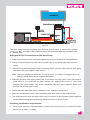
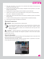
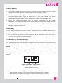
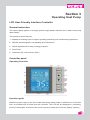
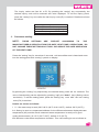
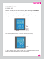
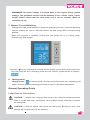
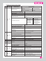
User Manual
& GUARANTEE CARD
Heat Pump Water Heater -
Domestic
R
R
Dear Customer,
Thank you for purchasing Venus Heat Pump Water Heater. We have
enclosed this handy installation manual to help you correctly install
your system and in getting the maximum performance out of it.
There is also a section called “Trouble Shooting Guide” to assist you
in setting right minor problems.
We wish you and your new “VENUS HEAT PUMP WATER HEATER”
a lifetime of happy association .
WARNING
1. Before installing this product, read and follow all warning
notices and instructions which are included. Failure to follow safety
warnings and instructions can result in severe injury, death, or property
damage. Call 044-43401500 for additional free copies of these
instructions.
2. This Domestic Heat Pump Water Heater is specifically designed
for domestic hot water supply. Do not use it for any other applications.
.
1
R
Section 1
Introduction
Product Overview
Domestic Heat pump water heaters transfer heat from the ambient air to hot water tank,
providing the most energy efficient hot water supply as compared to gas, oil, or
electric heaters. Operation cost of domestic heat pump water heaters is 60%∼80%
less, saving your expenses in energy costs each year. Venus heat pumps are not only
highly efficient, but also easy and safe to operate. Venus domestic heat pump water heaters
are CE approved, using R407C refrigerant which is environmental-friendly and energy efficient.
General Features
1.
Using heat energy from ambient air and reproduces more heat energy, saving
60%~80% energy compared to traditional heaters.
2.
Providing hot water all the seasons for your house in domestic application.
3.
No potential danger of any inflammable, gas poisoning, explosion, fire, electrical shock
which are associated with other heating systems.
4.
A digital controller is incorporated to maintain the desired water temperature.
5.
Long-life and corrosion resistant composite cabinet stands up to severe climates.
6.
Japanese Panasonic rotary compressor ensures outstanding performance, ultra energy
efficiency, durability and quiet operation.
7.
Self-diagnostic control panel monitors and troubleshoots heat pump operations to
ensure safe and reliable operation.
8.
Intelligent digital controller with friendly user interface and blue LED back light.
9.
The heat pump can operate down to ambient air temperature of -10°C. (14° F.)
2
R
Section 2
Installation
The following general information describes how to install the domestic Heat pump
water heater.
Note: Before installing this product, read and follow all warning notices and
instructions. Only a qualified service person should install the heat pump.
Materials needed for Installation
The following items are needed and are to be supplied by the installer for all heat pump
installations:
1. Plumbing fittings.
2. Level surface for proper drainage.
3. Ensure that a suitable electrical supply line is provided. See the rating plate on the heat
pump for electrical specifications. Please take a note of the specified current rating. No
junction box is needed at the heat pump; Connections are made inside of the heat pump
electrical compartment. Conduit may be attached directly to the heat pump jacket.
4. It is advised to use PVC conduit for the electrical supply line.
5. Use a booster pump for pumping water in case of low water pressure.
6. A filter on the water inlet of tank is needed.
7. The plumbing should be insulated to reduce its heat loss.
Note: We recommend installing shut-off valves on the inlet and outlet water connections for
ease of serviceability.
3
R
Domestic Heat Pump Water Heater Specification
1250
Ø
Ambient
Ø
Ø
Ø
Inlet/Outlet
4
R
5.
Adequate water flow.
This manual provides the information needed to meet these requirements.
Review all application and installation procedures completely before continuing
the installation.
Installation Location
CAUTION!
1. DO NOT install the heat pump near to hazardous materials and places.
2. DO NOT install the heat pump under deep sloping roofs without gutters which
will allow rain water, mixed with debris, to be forced through the unit.
3. Place the heat pump on a flat slightly pitched surface, such as concrete or
fabricated slab.
This will allow proper drainage of condensation and rain water from the base of the
unit. If possible, the slab should be placed at the same level or slightly higher
than the filter system/equipment.
5
R
Installation details
All criteria given in the following sections reflect minimum clearances. However, each
installation must also be evaluated, taking into account the prevailing local conditions such
as proximity and height of walls, and proximity to public access areas. The heat pump must
be placed to provide clearances on all sides for maintenance and inspection.
1.
The installation area must have good ventilation and the air inlet/outlet must not be
hindered.
2.
The installation area must have good drainage and be built on a solid foundation.
3.
Do not install the unit in areas accumulated with pollutions like aggressive gas (chlorine
or acidic), dust, sand and leaves etc.
4.
For easier and better maintenance and troubleshooting, no obstacles around the unit
should be closer than 1000mm.(See Figure 1)
Over 1m
Air Inlet
Heat Pump
Over
1m
Over 1m
Air Outlet
Over 1m
Figure 1
6
R
5.
For the units which installed at the rack on the outer wall, the rack should be fixed with
wall-bolts. And the heat pump must be installed with shockproof bushes to prevent
vibration and/or imbalance.
6.
Even though the controller is waterproof, care should be taken to avoid direct sunlight
and high temperature. In addition, the heat pump should be placed to ensure quality
viewing of the controller.
7.
The plumbing pipes must be installed with proper support to prevent possible damage
due to vibration.
Running water pressure should be kept 0. 2 Mpa to 0. 6Mpa. Otherwise, booster pump
or pressure reducing valve should be installed.
8.
The acceptable operating voltage range should be within ±10% of the rated voltage.
When heat pump units are installed in parallel, ensure that the voltage differences,
between these units, are within ±2%.
9.
The heat pump unit must be grounded /earthed for safety purposes.
10. If possible, the unit can be installed with auxiliary facility of rain, snow and sunlight proof.
Drainage and Condensation
Condensation will occur from the evaporator when the unit is running and drain at a steady
rate, depending upon ambient air temperature and humidity. The more humid the ambient
conditions, the more condensation will occur. The bottom of the unit acts as a tray to catch
rainwater and condensation. Keep the drain holes, located on the bottom pan of the unit
base, clear from debris at all times.
For the units which installed at the rack on the outer wall, proper drain hose should be
connected to the heat pump for condensation drainage.
Water Connections
Plumbing materials needed
Main Drain, Filter, Heat Pump, Ball Valve, Water Pump, One-way Valve.
Symbol
Name
Symbol
Name
Ball Valve
One-way Valve
Filter
Flow Direction
7
R
Figure 2
The heat pump must be protected from Reverse flow of water. If there is any chance
provide a check valve between the water tank and the cold water inlet.
Refrigerant Pipe Connections at the Heat Pump
1. Wrap up the thin and thick connecting pipes and a wire to length with insulated band.
2. Screw off the two/three way stop valve and the caps of insulated water tank inlet and
outlet.
3. Take off the plastic blockage of the connecting pipes, connect them with the heat pump
and water tank, and tighten it with wrench.
Note: The force should be moderate. Too much effort, it’s easier to damage the joint,
while too small effort, the joint cannot be sealed.
4. Remove the spool and valve needle cap of two/three way stop valve, open the spool of
small valve to 1/2 circle with an Allen wrench. On hearing the sound of gas flow,
withstand the valve needle core of the refrigerant inlet for 3 secs, repeat 3 times until
you feel the exhaust gas is cold.
5. Check the joints with soap water if leakage or not. Leakage cannot exist.
6. Open the two/three way stop valve completely with Allen wrench, and seal the cap.
7. The replenishment valve and stop valve may be required to be insulated, which depends
on the ambient temp at local, lest they freeze and burst in winter in use.
Plumbing installation requirements
1. When water pressure exceeds 0. 6Mpa, please use reducing valve to reduce the water
pressure to 0. 3Mpa – 0. 6Mpa.
8
R
2.
Each part connected to unit needs to be connected with method of loose joint and
installed with intermediate valve.
3.
Ensure that all plumbing has been properly completed and then proceed to do a water
leakage and pressure test.
4.
All the pipelines and pipe fittings must be insulated to prevent heat loss.
5.
Install a pressure release valve at the highest point of the system of heat preservation
tank, and it is advised to be installed outside.
6.
Install a drain valve at the lowest point of the system to enable the system to be drained
during cleaning .
7.
In order to reduce the back pressure, the pipes should be installed horizontally.
8.
And minimize the elbows (90 degrees connections).
Electrical Connections
WARNING —Risk of electrical shock or electrocution.
Ensure that all high voltage circuits are disconnected before commencing heat
pump installation. Contact with these circuits could result in death or serious
injury to users, installers or others, due to electrical shock and may also cause
damage to property.
CAUTION — Label all wires prior to disconnection when servicing the heat pump.
Wiring errors can cause improper and dangerous operation. Check and ensure proper
operation after servicing.
General Information
Wiring connections must be done according to the wiring diagram found on the inside of the
heat pump access panel or see addendum A.
The heat pump must be grounded / earthed. A ground Terminal is provided on the inside
of the heat pump electrical compartment. (See Figure 3)
Single System Single Phase
(Figure 3)
9
R
Power supply
1.
If the supply voltage is too low or too high, it can cause damage and/or result in unstable
operation of the heat pump unit, due to high in rush currents on start up.
2.
The minimum starting voltage should be above 90% of rated voltage. The acceptable
operating voltage range should be within ±10% of the rated voltage. The voltage
difference between phases of a three phase power supply should be within ±2%.
3.
Ensure the cable specifications meet the correct requirements for the specific
installation. The distance between the installation site and mains power supply will affect
the cable thickness. Follow the local electrical standards to select the cables, circuit
breakers and isolator breakers.
Grounding
In order to prevent electrical shock in case of leakage from unit, install the domestic air to
water heat pump water heater according to electrical standards.
1.
Do not interrupt the voltage supply to the heat pump frequently as this may result in
a shorter life expectance of the heat pump.
Controller PC board Settings
The Controller PCB has a pin selectable toggle switch which must be set according to the
specific installation requirement.
NOTE:
Before any changes are made to the pin settings, ensure that the mains supply power
is OFF at the circuit breaker or physically disconnected from the mains supply.
The single system heat pump unit controller PC Board consists of a 3-pin selectable toggle
switch.
ON
OFF
1
2
3
Single system and single phase
Figure 4: Switch Layout
Note: When switch 1 is set to OFF, circulation pump will function. ON, it doesn’t.
When switch 2 is set to OFF, electric heating will function. ON, it doesn’t.
When switch 3 is set to OFF, expansion valve will function. ON, it doesn’t.
10
R
Factory Default Setting
Description
Switch1
Switch2
Switch3
1 phase, Domestic air
to water heat pump
water heater, Cycle
heating
ON
ON
ON
Electrical Wiring Diagram
11
R
Section 3
Operating Heat Pump
LCD User-Friendly Interface Controller
General instruction
The control panel applies to a single system single phase domestic air to water heat pump
water heater.
The operation panel features:
1. Capacitive touching keys for higher operating sensitivity and unlimited key operations.
2. Minimal electromagnetic susceptibility and interference.
3. Stylish appearance for easy viewing purposes.
4. Dust Proof.
5. Automatic Key Lock function (AKL).
Controller panel
Operating Controller
Operation guide
When the power supply to the air to water heat pump water heater is switched on for the first
time, an audible tone is heard from the controller. The LCD will be displayed in a dimming
mode (no back light). At this time the touch keys are locked (see “lock key display” symbol).
12
R
Keys explanation:
Unlocking Keys: Press the “power” key for 3 seconds until you hear an audible tone, then
release the key. The back light of the LCD display will turn on and the key pad is unlocked
with no “lock key display” symbol. The keypad will automatically lock after 60 seconds,
displaying the “lock key display” symbol.
“ power” key: By pressing the “power” key, the unit can be switched ON or OFF.
“up” and “down” keys: Press to Increase and Decrease values.
“setting” key: Press for Inquiry, Parameter and Password setting
“timer” key: Press for timer setting, timer eliminate and clock setting.
Controller Set-Up
1. Temperature setting:
Make sure key-pad is unlocked. Press the “up” key, “temperature setting” symbol is
flashing and the set temperature is displayed. Press the “up” key again, the displayed
temperature will increase. Press the “down” key, “temperature setting” symbol is flashing
and the set temperature is displayed. Press the “down” key again, the displayed
temperature will decrease. The range of water temperature can be set from 20°C (68°F)
to 60°C (140°F) (default = 55°C (131°F)).
2. System status display values:
Make sure key-pad is unlocked. Press the “setting” key and enter into inquiry panel
with “inquire” symbol on display.
13
R
The inquiry codes are from A1 to Er. By pressing the “setting” key sequentially, the
desired inquiry code will be selected and value displayed. To exit the inquiry panel,
press the “setting” key once after the last inquiry code (Er) is reached. Details are shown
as follows:
A1—coil pipe temp.
A2—compressor suction temp.
A3—compressor discharging temp.
A4—ambient temp.
Er—error code
3. Parameter setting:
NOTE:
THESE
SETTINGS
ARE
PRE-SET
ACCORDING
TO
THE
MANUFACTURER’S SPECIFICATION FOR SAFE HEAT PUMP OPERATIONS. DO
NOT CHANGE THESE SETTINGS AS IT WILL INFLUENCE THE SAFE OPERATION
OF THE HEAT PUMP.
Press the “setting” key for more than 3 seconds, until an audible tone is heard and enter
into the setting panel with “setting” symbol on display.
By pressing the “setting” key sequentially, the desired setting code will be selected. The
value of each setting can be adjusted by pressing “up” and “down” keys (Setting values
see below). To exit the setting panel, press the “setting” key once after the last setting
code (P6) is reached.
Details are shown as follows:
/ / / - Set water temp in tank (30°C-99°C (86°F~210.2140°F), default: 50°C(122°F))
L1- Setting is used to compensate/calibrate for the difference between displayed water
temperature (A6) and the actual measured water temperature in tank (use a good
quality thermometer). (0~15°C (32°F~59°F), default: 0°C (32°F))
L2- Minimum outlet water temperature deviation. This value setting is set to indicate to
14
R
the compressor when to re-start until desired temperature is reached. (3~18°C
(37.4~64.4°F) default: 5°C (37.4°F)). For example, set water temp. = 25°C (77°F), L2 =
5°C (41°F), the compressor will stop at 25°C (77°F) and re-start at 20°C (68°F)
L4- Desired water temperature limit (30~99°C (86~210.2°F) default: 60°C (140°F))
L5- allowed electric heating ambient temperature (0~35°C (32~), default: 7°C (44.6°F),
where 0°C (32°F) means no electric heating).
L9- Two speeds wind temp control the fan motor. (10°C -45°C (50°F~113°F), default:
45°C (113°F)) (Not Applicant)
H1-defrosting period (20~99 minutes default: 45 minutes)
H2- defrosting start temperature (1~-15°C (33.8~5°F) default: -1°C (30.2°F))
H3-defrosting time (5~20miniutes default: 8 minutes)
H4-defrosting exiting temperature (1~40°C (33.8~104°F), default: 20°C (68°F))
P1-electronic expansion valve regulation cycle (20~180 seconds, default: 60 seconds)
P2- degree of super heat (-8~15°C(17.6~59°F)
, default 0°C(32°FZ))
P3- allowed discharge temperature (70~135°C (158~275°F), default: 92°C (197.6°F))
P4- expansion valve opening as four-way valve is defrosting (6~55°C (42.8~), default:
32 °C (89.6°F))
P5-expansion valve minimum opening (6~30°C (42.8~86°F), default: 15°C (57°F))
P6-super heat compensation (0~12 default: 4)
Note: If the controller is chosen with electronic expansion valve not used (the toggle
switch 3 on controller PC Board is on OFF.), it doesn’t display P1-P6 when setting.
4. Clock setting:
Press the “timer” key for more than 8 seconds until an audible tone is heard and the
“timer” symbol disappears. The hour value is flashing and can be adjusted by pressing
“up” and “down” keys. Press the “timer” key for minute adjustment and repeat as
previous. Press the “timer” key to exit.
5. Timer setting:
The heat pump consists of two separate timing functions. Timer 01 and 02 are used to
set the ON/OFF times of the heat pump within 24 hour period.
15
R
Heat pump ON/OFF timers:
01—ON/OFF timing
02—ON/OFF timing
Press the “timer” key and enter timer 01 ON time. Set the ON time as in Clock Setting
section. Press “timer” key again to set timer 01 OFF time. Set the OFF time as in Clock
Setting section. Repeat sequence until all timer settings are completed.
If, however, a timer is not used, set ON and OFF times to 00:00. Timer setting can be
randomly selected. For example, Timer 01 ON, Timer 02 OFF.
After completing all timer settings, the controller will display the following:
To cancel the timer feature, press the “timer” key for more than 3 seconds until an
audible tone is heard, then release key, timer is now cancelled.
16
R
6. Installer Password Control :
This feature enables the installer/agent to have control and use of the normal operation
of the heat pump on a monthly basis by monthly password control. For example: If there
is an agreement which involves monthly installment, the installer/agent can utilize this
feature by applying password control.
Press the “setting” key for more than 3 seconds until an audible tone is heard and
release key, enter into setting panel with “setting” symbol and “L” settings on display.
Press the “setting” key for more than 8 seconds until an audible tone is heard and
release key, enter into Password Control with “C” on display.
Set-up installer/agent Password
The installer/agent Password consists of 4 groups of double digit numbers (C1 to C4
with range from 00 to 99). Choose your Password carefully to avoid any unauthorized
access. For example: If C1 = 79, C2 = 04, C3 = 33 and C4 = 07 then the Password
is 79043307.
Now enter C5. C5 (range from 01 to15, 00 disables installer/agent Password) indicates
the period in number of month(s), 30 days/month. For example: C5 = 08, the unit will be
disabled after 8 months (240 days). To enable the unit, Password is needed.
How to enable the unit
Press the “setting” key for more than 3 seconds until an audible tone is heard and
release key, enter into setting panel with “setting” symbol and “L” settings on display.
Then press the “setting” key for more than 8 seconds until an audible tone is heard and
release key, enter into Password Control with “C” on display. Input Password to enable
the heat pump and reset C5 (range from “01” to “15”, “00” disables installer/agent
Password) to desired period. If an incorrect password is provided the heat pump the
Error Code 11E will be displayed.
Forgotten/Reset Password
This function enables the installer/agent to enable the heat pump unit in the event of a
forgotten password. All preset settings will be reverted back to the original factory
default settings once the heat pump is enabled.
Make sure that the lock symbol “
“is on display, press the “setting” key until an
audible tone is heard and the display back light is lit, release key. The clock will now
display, “00:” and the heat pump unit is enabled.
17
R
REMEMBER: All preset settings is reverted back to the original factory default
settings. The password function will be disabled (C1=01, C2=01, C3=01, C4=01,
C5=00). Please ensure that the heat pump unit is set up correctly. (Refer to
controller set-up)
7. Manual / Forced Defrosting:
Although this heat pump features an automatic defrosting function, a manual defrosting
function enables the user to manually defrost the heat pump when unusual frosting
appears.
Make sure key-pad is unlocked. Ensure that heat pump unit is in running mode,
displaying the heat symbol.
Press the “ ”key for more than 8 seconds until an audible tone is heard, and release key.
The heat pump will be in defrosting mode and the “defrost” symbol will be on display-.
8. Heating mode:
Heating mode--:
In heating mode, the heat pump will function as a swimming pool
heater, ensuring that the swimming pool water is kept to a set water temperature.
General Operating Guide
Initial Start-up Precautions
CAUTION — Refrain from using this heat pump if any electrical components have
been in contact with water. Immediately call a qualified service technician to inspect
the heat pump.
CAUTION — Keep all objects clear above the heat pump. Blocking air flow could
damage the unit and may void the warranty.
18
R
Section 4
General Maintenance
Controller Error Codes
The following Common Error Codes for the heat pump units will be displayed on the
controller panel:
Common Error Code
CODE
05E
06E
NAME
Compressor high pressure and/or
faulty switch
Compressor low pressure and/or
faulty switch
CODE
NAME
15E
Faulty inlet water temperature sensor
16E
Faulty Evaporator (heating) pipe sensor
09E
Controller communication
18E
11E
Installer password control
21E
12E
Compressor high discharge
temperature
29E
Abnormal compressor discharge temperature and/or
Faulty compressor discharge temperature sensor
Ambient temperature too low and/or Faulty ambient
temperature sensor
Faulty compressor suction temperature sensor
Inspection and Service
Venus domestic heat pump water heaters are designed and built to provide long life
perf ormance, when installed and operated properly under normal conditions. Periodic
inspections are important to keep your heat pump running safely and efficiently.
Owner Inspection
Venus recommends that inspections on heat pumps are done frequently, especially after
abnormal weather conditions. The following basic guidelines are suggested for your
inspection:
1
Make sure the front of the unit is accessible for future service.
2.
Keep the top and surrounding areas of the heat pump clear of debris.
3.
Keep all plants and shrubs trimmed and away from the heat pump especially the
area before the fan.
4.
Keep lawn sprinklers from spraying on the heat pump to prevent corrosion and
damage.
5.
Ensure that the ground wire is always properly connected.
6.
The filter must be maintained on a regular basis in order to ensure clean and
healthy water to protect the heat pump from damaging.
20
R
7.
Keep inspecting power and electrical components’ wiring to make sure their normal
operation.
8.
All the safety protection devices have been preset by manufacturer ; please refrain
from changing these settings. If any changes are needed, please contact the
authorized installer/agent.
9.
If the heat pump is installed under roof without a gutter, ensure that all measures
are taken to prevent excessive water from flooding the unit.
10. Do not use this heat pump if any electrical part has been in contact with water.
Contact a authorized installer/agent.
11. If the increase of power consumption is not due to cold weather, please consult
with the local authorized installer/agent.
12. Please turn off the heat pump and disconnect it from the mains power supply,
when not in use for a prolonged period of time.
Troubleshooting
Use the following troubleshooting information to resolve issues/problems with your
heat pump.
WARNING — RISK OF ELECTRICAL SHOCK OR ELECTROCUTION.
Ensure that all high voltage circuits are disconnected before commencing heat
pump installation. Contact with these circuits could result in death or serious
injury to users, installers or others, due to electrical shock and may also cause
damage to property.
DO NOT open any part of the heat pump as this may result to electrocution.
1.
Keep your hands and hair clear of the fan blades to avoid injury.
2.
If you are not familiar with your heater:
a)
DO NOT attempt to adjust or service the unit without consulting your authorized
installer/agent.
b) PLEASE read the complete Installation and/or User’s Guide before attempting to
operate service or adjust the heater.
IMPORTANT: Turn off the mains power supply to the heat pump prior to attempting
service or repair.
21
R
Problems and Corrective Action
NO.
1
Problem
Description
Error code
05E
Possible Cause
a) The pool water temperature
sensor and PC Board are not
Use the correct sensor.
1. Measured Pool Temp <
compatible.
Actual Pool Temp
b) The pool temperature sensor is Position the sensor
not in the correct position.
correctly.
2. The Y shaped filter is blocked or
Clean the filter.
jammed resulting into lower water flow.
3. No water in pool or is lower than the
Fill the pool with water.
water inlet (Weir).
4. The plumbing is blocked or the valves
Repair or replace the plumbing and/or valves.
are damaged or closed.
1. Remove air lock from the system.
5. Too much air in the plumbing result in
2.
Make sure that the circulation pump is working
reduction in flow rate.
correctly.
a) Circulation
Repair or replace
pump damaged.
circulation pump.
6. Circulation pump faulty.
8. Control cable of the high pressure
switch damaged or disconnected.
Replace the damaged cable or reconnect.
9. High pressure switch can not be reset.
Replace high pressure switch.
10. Input of the high pressure sensor is
shorted with common, error code 05E is
still displaying.
Replace the PC Board.
2. Control cable of the high pressure
switch damaged or disconnected.
3
4
Error Code
09E
Error Code
11E
6
7
Error Code
12E
Error Code
15E
Error Code
16E
Find the cause of blockage and replace the filter
and/or re-vacuum the system.
Detect leakage and repair. Vacuum, charge refrigerant
and start heat pump.
Replace the damaged cable or reconnect.
3. Low pressure switch cannot be reset.
Replace low pressure switch.
4. Input of the high pressure sensor is
shorted with common, error code 05E is
still displaying.
Replace the PC Board.
5. The refrigeration system is blocked (by
ice or dirt).
1. The controller cable damaged or
disconnected.
1. Incorrect installer/agent control
password.
Find the cause of blockage and replace the filter
and/or re-vacuum the system.
Replace damaged controller cable or reconnect.
Input the correct control password.
2. Compressor discharge temperature
sensor faulty or damaged.
3. PC Board damaged.
Charge the correct volume of refrigerant specified on
the label.
Replace the compressor discharge temperature
sensor.
Replace the PC Board.
1. Pool temperature sensor damaged.
Replace pool temperature sensor.
1. Insufficient refrigerant charge volume.
5
Install correct circulation
pump for specific
application or shorten the
distance between
circulation pump and/or
the heat pump and/or
other equipment.
Charge the correct volume of refrigerant specified on
the label.
1. Refrigerant leakage.
Error code
06E
b) Circulation
pump is too small
or the distance
from the heat
pump is too far.
7. Excessive refrigerant charge volume.
11. The refrigeration system is blocked
(by ice or dirt).
2
Corrective Action
2. Pool temperature sensor connector
(plug) disconnected and/or oxidized due
to damp or water.
3. The controller and/or PC Board faulty
or damaged.
1. Defrost temperature sensor faulty or
damaged.
2. Defrost temperature sensor connector
(plug) disconnected and/or oxidized due
to damp or water.
3. The controller and/or PC Board faulty
or damaged.
Reconnect or clean pool temperature sensor and wrap
it with insulation tape.
Replace the controller or PC Board.
Replace the defrost temperature sensor.
Reconnect or clean defrost temperature sensor and
wrap it with insulation tape.
Replace the controller or PC Board.
22
R
8
Error code
18E
9
Error code
21E
10
Error code
29E
1. Compressor discharge temperature
Replace the compressor discharge temperature
sensor faulty or damaged.
sensor.
2. Compressor discharge temperature
Reconnect or clean compressor discharge
sensor connector (plug) disconnected
temperature sensor and wrap it with insulation tape.
and/or oxidized due to damp or water.
3. The controller and/or PC Board faulty
Replace the controller or PC Board.
or damaged.
1. Ambient temperature sensor faulty or
Replace the Ambient temperature sensor.
damaged.
2. Ambient temperature sensor connector
Reconnect or clean Ambient temperature sensor and
(plug) disconnected and/or oxidized due
wrap it with insulation tape.
to damp or water.
3. The controller and/or PC Board faulty
Replace the controller or PC Board.
or damaged.
1. Compressor suction temperature
Replace the Compressor suction temperature sensor.
sensor faulty or damaged.
2. Compressor suction temperature
Reconnect or clean Compressor suction temperature
sensor connector (plug) disconnected
sensor and wrap it with insulation tape.
and/or oxidized due to damp or water.
3. The controller and/or PC Board faulty
Replace the controller or PC Board.
or damaged.
3. Check whether the thermal relay is damaged, if so,
replace.
1. User's incorrect operation and/or
parameter settings.
11
The heat
pump is not
heating
2. Problem with controller or PC Board.
a) The pool
temperature setting
is set too low and
the desired
temperature cannot
be reached.
b) The difference
between the
required pool
temperature and
the heat pump
restart temperature
(L2) is too big.
c) Timer function
has been set to a
specific ON and
OFF time, which
does not allow
sufficient time for
the heat pump to
operate.
Re-set the pool water
temperature to the correct
range.
Re-set by reducing the value of
L2.
Re-set the timer.
d) No electrical
power supply to the
heat pump (no
display on the
controller).
1. Check and ensure that circuit
breakers are ON.
2. Test voltage on the PC Board
L/N/G Connectors.
3. If power is not restored,
replace cable.
a) The temperature
displayed is more
than 45˚C.
Check the pool water
temperature sensor, replace if
faulty.
b) PC Board is
damaged due to
burnt relays.
c) PC Board
microcontroller chip
faulty.
Check and find out the cause,
find faulty relay(s) and replace.
Replace the PC Board.
23
R
12
Slow
increase of
water
temperature
1. Insufficient refrigerant.
2. The heating capacity of the heat pump
is insufficient for the size of the pool.
3. Serious residues/dirt occurred on the
heat exchanger.
4. The evaporator coil is dirty or jammed
and this will affect the heat exchange
efficiency.
1. Check for leakages, if found, repair and re-charge
refrigerant as per volume specification on label.
2. If no leakage was found, re-charge refrigerant as
per volume specification on label.
Increase the size or number of heat pump units.
Clean the heat exchangers.
Clean the evaporator coil.
5. Poor design of insulation for the pool.
It is recommended to use a pool insulation cover.
6. The length of the pipes is too long
and/or improperly insulated.
1. If the length of the pipes cannot be done, ensure
well insulated piping.
1. The controller cable damaged or
disconnected.
2. PC board damaged.
3. Pool temperature sensor and/or cable
disconnected or damaged.
Reconnect or replace controller cable and wrap it with
insulation tape.
Replace PC Board.
Reconnect or replace pool temperature sensor and
wrap it with insulation tape.
a) The main power supply
Reconnect or replace
cables is disconnected or
the mains power supply
damaged.
cable.
Check and ensure that
the mains power supply
cable', length and
thickness, is within the
b) The main power supply
voltage is lower than 175V. specifications, if not
replace with thicker
cable to ensure less
voltage drop.
2. Increase the size and number of heat pump units.
13
The
controller
displays
''00''
1. Mains power supply is abnormal.
14
No display
on the
controller
2. PC board power cable is disconnected
or the fuse is burnt.
3. PC Board transformer is damaged.
4. The controller cable damaged or
disconnected.
5. PC Board damaged.
1. Fan motor capacitor damaged (under
this circumstance the fan motor will
overheat).
15
16
The fan
does not
operate
The
compressor
does not
operate
while the fan
is working
Reconnect PC Board cable or replace the fuse.
Replace the PC Board transformer.
Reconnect or replace controller cable and wrap it with
insulation tape.
Replace the PC board.
Replace fan motor capacitor.
2. The motor windings has been burnt.
Repair or replace the fan motor.
3. The display is ON but heat pump unit
is not in running mode/ON.
Press the power button and turn On the heat pump
unit.
4. Fan motor relay damaged.
Check and replace if damaged.
5. No fan motor output from PC Board.
Replace PC board.
6. Fan motor cable disconnected or
damaged.
1. Compressor damaged (under this
circumstance the compressor motor will
overheat).
2. Compressor connecting cable is burnt.
3. The compressor windings have been
burnt.
4. The compressor is jammed or blocked.
5. AC contactor does not work.
Reconnect or replace fan motor cable.
Replace compressor capacitor.
Replace compressor connecting cable.
Repair or replace the compressor.
Repair or replace the compressor.
Replace the AC contactor.
a) The AC contactor
winding is damaged or
the contactor is
jammed and cannot
close.
24
R
Frost or ice
c) No compressor relay
output from the PC
Board.
Check and/or replace
compressor relay or PC
Board.
6. Thermal relay damaged.
Replace the thermal relay.
1. Fan is not working.
Refer to "problem description No.15 ".
1. Find the cause of blockage and replace the filter
and/or re-vacuum the system.
2. Check for leakages, if found, repair and re-charge
refrigerant as per volume specification on label.
3. If no leakage was found, re-charge refrigerant as
per volume specification on label.
2. Insufficient refrigerant or the
refrigeration system is blocked.
17
b) The main power
supply voltage is lower
than 175V.
Check and ensure that the
mains power supply cable',
length and thickness, is
within the specifications, if
not replace with thicker
cable to ensure less voltage
drop.
3. The defrost parameter is not set
correctly.
4. The defrost sensor is not placed
correctly.
5. The 4-way valve cannot be reversed
(The winding is damaged or the valve
cannot be correctly reversed).
6. Controller is damaged.
7. The refrigeration system has a
problem.
Re-set the defrost parameter to the correct value.
Replace the defrost sensor to the correct position.
Check the 4-way valve to find the cause replace the
winding or the 4-way valve.
Replace the controller.
Check and repair refrigeration system.
25
R
Section 5
Components assembly
Illustrated Parts
VDH 100 / VDH 200
ITEM
DISCRIPTION
QTY
ITEM
1
2
3
Base Plate
Compressor, Rotary
Evaporator
Fan Motor/Fan Motor/ Fan
Guard
Medium Partition
Four-way Valve
Filter
Pressure Release Valve
3’’ Stop Valve
1
1
1
10
11
12
4’’ Stop Valve
Small Fixing Plate
Electronic compartment Board
1
1
1
1
13
Side Panel
1
1
1
2
1
1
14
15
16
17
18
Fan Panel
Fan Net
Valve Panel
Back Net
Top Board
1
1
1
1
1
4
5
6
7
8
9
DISCRIPTION
QTY
26
R
WARRANTY
Venus Heat Pump Water Heater & Tank are covered by warranty for
a period of 1 year from the date of purchase, against manufacturing defects
of all functional parts.
This warranty excludes any damages due to misuse, accident, negligence,
tampering, unauthorized repair and normal wear and tear.
Please preserve this warranty Card along with the paid Bill from our
Dealer. These Documents must be presented to the Service Centre to
avail this warranty.
Customer Name :…………………………… Model No : ………………………............…….
Address : ……………………………………… Serial No : …………….......................…………………..
……………………………………………….... Invoice No : …................................................
……………………………………………….... Date of Purchase: …......................................
Dealer's Name and Address :
Dealer's Signature
Warranty
SERVICE LOG
Date
Description of
complaint
Within
Warranty.
Outside
Warranty.
Signature
If you have any questions, problem or requierments of spare parts, get in touch with us for immediate attention at
The Customer Care Cell
Venus Home Appliances (P) Ltd.
4/993, Kamaraj Street, Rajiv Gandhi Salai, (OMR)
Perungudi Post, Kottivakkam, Chennai - 600 096.
Tel: +91 44 43401550, 43401515. Fax: +91 44 43401525.
e-mail: [email protected]
www.venushomeappliances.com
EAST ZONE
128/6, Ground Floor,
Hazra Road, Kolkatta - 700 026
Tel: 033 - 40181500, 24552842. Fax : 24555124
E-mail: [email protected]
No. 37, Near Dhoom Resturant,
National Highway Road, Beharbari,
Beltola, Guwahati -781 029. Tel : 0361-2236102
E-mail: [email protected]
WEST ZONE
213, Second Floor,
Shree Ganesh Industrial House,
Waman Tukaram Patil Marg,
Chembur, Mumbai - 400 071.
Tel: 022-25207575, 25207576
E-mail: [email protected]
F-95, Road No-7, Godown No.13
Vishkarma Industrial Area
Jaipur - 302013.
Rajasthan.
Tel: 0141 - 4101561
E-mail: [email protected]
House No.47, Rani Talab Road,
Digiana, Jammu - 180 010.
Tel: 0191 - 2459859 / 2459958
E-mail: [email protected]
SOUTH ZONE
4/993, Kamaraj Street,
Rajiv Gandhi Salai (OMR), Kottivakkam,
Perungudi, Chennai - 600 096.
Tel: 044-43401550. Fax: 044-43401525
E-mail: [email protected]
D.F.61, Scheme No.74C
Vijay Nagar, Indore - 452 001.
Madhya Pradesh
Tel : 0731-4050844
E-mail : [email protected]
Srinath Lake View,
SF - 1, Bye Pass Road, Chungam,
Coimbatore - 641045. Tel: 0422 - 2322339
E-mail: [email protected]
K-45 Peoples Co-Operative Colony,
Kankarbagh, Hanuman Nagar,
Patna - 800 020.
Tel : 0612 - 2359960
E-mail : [email protected]
7/1, 3rd Main, 12th Cross, (Opp: S.B.I.)
Wilson Garden, Bangalore - 560030,
Tel: 080-22237592. Fax: 22483679
E-mail: [email protected]
NORTH ZONE
A-49, II Floor, Mayapuri Industrial Area,
Phase - 1, New Delhi - 110 064.
Tel : 011 - 2811 5401/02
E-mail : [email protected]
CEN-16, Palco House, Village Darua,
Opp Railway Station, Chandigarh - 160 019
Tel: 0172-5078160, 161
E-mail: [email protected]
C-46, Ground Floor, Sector-2
Noida - 201 301 (U.P.)
Tel: 0120 - 2549638, 4316298
E-mail: [email protected]
39/5455, Kurisupally Road, Ravipuram,
Ernakulam, Cochin - 682 015. Kerala
Tel: 0484-2356067. Fax: 2380340
E-mail: [email protected]
H.No.32, Sanjeevaiah Co-op, Housing Colony,
Tarbund ‘X’ Road (Sikh Village)
Secunderabad - 500 009. Tel: 040-27896187, 186
E-mail: [email protected]
36/33, Arunachala Arcade, Opp.Hotel Taj,
TPK Road, Pasumalai, Madurai - 625 004.
Tel: 0452 - 2373010
E-mail: [email protected]
Regd.Office & Factory:
5/54A, Senthilampannai, Tuticorin - 628103. Tamilnadu.
Tel: +91-461-2271891/892/893 Fax: +91-461-2271890
E-mail: [email protected]