1
AMD Geode™ GeodeROM
Functional Specification
March 2006
Publication ID: 32087C
AMD Geode™ GeodeROM Functional Specification
© 2006 Advanced Micro Devices, Inc. All rights reserved.
The contents of this document are provided in connection with Advanced Micro
Devices, Inc. (“AMD”) products. AMD makes no representations or warranties with
respect to the accuracy or completeness of the contents of this publication and
reserves the right to make changes to specifications and product descriptions at
any time without notice. No license, whether express, implied, arising by estoppel
or otherwise, to any intellectual property rights is granted by this publication.
Except as set forth in AMD’s Standard Terms and Conditions of Sale, AMD
assumes no liability whatsoever, and disclaims any express or implied warranty,
relating to its products including, but not limited to, the implied warranty of merchantability, fitness for a particular purpose, or infringement of any intellectual
property right.
AMD’s products are not designed, intended, authorized or warranted for use as
components in systems intended for surgical implant into the body, or in other
applications intended to support or sustain life, or in any other application in which
the failure of AMD’s product could create a situation where personal injury, death,
or severe property or environmental damage may occur. AMD reserves the right to
discontinue or make changes to its products at any time without notice.
Trademarks
AMD, the AMD Arrow logo, and combinations thereof, and Geode, XpressAUDIO, XpressGRAPHICS, and Virtual System
Architecture are trademarks of Advanced Micro Devices, Inc.
Microsoft and Windows are registered trademarks of Microsoft Corporation in the United States and/or other jurisdictions.
Other product names used in this publication are for identification purposes only and may be trademarks of their respective
companies.
2
AMD Geode™ GeodeROM Functional Specification
Contents
32087C
Contents
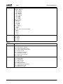
List of Figures . . . . . . . . . . . . . . . . . . . . . . . . . . . . . . . . . . . . . . . . . . . . . . . . . . . . . . . . . . 7
List of Tables . . . . . . . . . . . . . . . . . . . . . . . . . . . . . . . . . . . . . . . . . . . . . . . . . . . . . . . . . . . 9
1.0
Overview . . . . . . . . . . . . . . . . . . . . . . . . . . . . . . . . . . . . . . . . . . . . . . . . . . . . . . . . . 11
1.1
1.2
1.3
2.0
Introduction . . . . . . . . . . . . . . . . . . . . . . . . . . . . . . . . . . . . . . . . . . . . . . . . . . . . . . 17
2.1
2.2
3.0
INT 1Ah, Function B1h PCI BIOS Subfunctions Descriptions . . . . . . . . . . . . . . . . . . . . . . . . . . 75
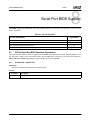
Serial Port BIOS Support . . . . . . . . . . . . . . . . . . . . . . . . . . . . . . . . . . . . . . . . . . . 83
8.1
9.0
ATA Device INT 13h Support . . . . . . . . . . . . . . . . . . . . . . . . . . . . . . . . . . . . . . . . . . . . . . . . . . . 43
INT 13h Functions Descriptions . . . . . . . . . . . . . . . . . . . . . . . . . . . . . . . . . . . . . . . . . . . . . . . . . 44
INT 13h Extensions API . . . . . . . . . . . . . . . . . . . . . . . . . . . . . . . . . . . . . . . . . . . . . . . . . . . . . . . 56
INT 13h ATA Device (Fixed Disk) Data Structures . . . . . . . . . . . . . . . . . . . . . . . . . . . . . . . . . . . 62
INT 41h/46h Vectors . . . . . . . . . . . . . . . . . . . . . . . . . . . . . . . . . . . . . . . . . . . . . . . . . . . . . . . . . 67
PCI Support . . . . . . . . . . . . . . . . . . . . . . . . . . . . . . . . . . . . . . . . . . . . . . . . . . . . . . 73
7.1
8.0
Floppy Disk Drive Support . . . . . . . . . . . . . . . . . . . . . . . . . . . . . . . . . . . . . . . . . . . . . . . . . . . . . 31
INT 13h Functions Descriptions . . . . . . . . . . . . . . . . . . . . . . . . . . . . . . . . . . . . . . . . . . . . . . . . . 31
Non-Removable Media . . . . . . . . . . . . . . . . . . . . . . . . . . . . . . . . . . . . . . . . . . . . . 43
6.1
6.2
6.3
6.4
6.5
7.0
Post Codes . . . . . . . . . . . . . . . . . . . . . . . . . . . . . . . . . . . . . . . . . . . . . . . . . . . . . . . . . . . . . . . . 27
Removable Media . . . . . . . . . . . . . . . . . . . . . . . . . . . . . . . . . . . . . . . . . . . . . . . . . . 31
5.1
5.2
6.0
User Directory . . . . . . . . . . . . . . . . . . . . . . . . . . . . . . . . . . . . . . . . . . . . . . . . . . . . . . . . . . . . . . 25
Overrides . . . . . . . . . . . . . . . . . . . . . . . . . . . . . . . . . . . . . . . . . . . . . . . . . . . . . . . . . . . . . . . . . . 26
POST . . . . . . . . . . . . . . . . . . . . . . . . . . . . . . . . . . . . . . . . . . . . . . . . . . . . . . . . . . . . 27
4.1
5.0
Supported INT/Functions . . . . . . . . . . . . . . . . . . . . . . . . . . . . . . . . . . . . . . . . . . . . . . . . . . . . . . 17
Acronyms and Definitions . . . . . . . . . . . . . . . . . . . . . . . . . . . . . . . . . . . . . . . . . . . . . . . . . . . . . 24
Code Structure . . . . . . . . . . . . . . . . . . . . . . . . . . . . . . . . . . . . . . . . . . . . . . . . . . . . 25
3.1
3.2
4.0
Scope . . . . . . . . . . . . . . . . . . . . . . . . . . . . . . . . . . . . . . . . . . . . . . . . . . . . . . . . . . . . . . . . . . . . . 11
General Description . . . . . . . . . . . . . . . . . . . . . . . . . . . . . . . . . . . . . . . . . . . . . . . . . . . . . . . . . . 11
Features . . . . . . . . . . . . . . . . . . . . . . . . . . . . . . . . . . . . . . . . . . . . . . . . . . . . . . . . . . . . . . . . . . . 12
INT 14h Serial Port BIOS Functions Descriptions . . . . . . . . . . . . . . . . . . . . . . . . . . . . . . . . . . . 83
Parallel Port BIOS Support . . . . . . . . . . . . . . . . . . . . . . . . . . . . . . . . . . . . . . . . . . 87
9.1
INT 17h Parallel Port BIOS Functions Descriptions . . . . . . . . . . . . . . . . . . . . . . . . . . . . . . . . . . 87
AMD Geode™ GeodeROM Functional Specification
3
32087C
Contents
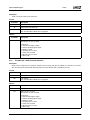
10.0 Human Interface Device Support . . . . . . . . . . . . . . . . . . . . . . . . . . . . . . . . . . . . . 89
10.1 INT 16h Functions Descriptions . . . . . . . . . . . . . . . . . . . . . . . . . . . . . . . . . . . . . . . . . . . . . . . . . 89
10.2 PS/2 Pointing Device Support . . . . . . . . . . . . . . . . . . . . . . . . . . . . . . . . . . . . . . . . . . . . . . . . . . 93
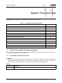
11.0 System Time and Date . . . . . . . . . . . . . . . . . . . . . . . . . . . . . . . . . . . . . . . . . . . . . . 95
11.1 INT 1Ah Time and Date Functions Descriptions . . . . . . . . . . . . . . . . . . . . . . . . . . . . . . . . . . . . 95
12.0 System Services . . . . . . . . . . . . . . . . . . . . . . . . . . . . . . . . . . . . . . . . . . . . . . . . . 101
12.1 INT 15h System Services Functions Descriptions . . . . . . . . . . . . . . . . . . . . . . . . . . . . . . . . . . 103
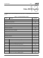
13.0 Video BIOS Support . . . . . . . . . . . . . . . . . . . . . . . . . . . . . . . . . . . . . . . . . . . . . . 163
13.1 INT 10h Functions Descriptions . . . . . . . . . . . . . . . . . . . . . . . . . . . . . . . . . . . . . . . . . . . . . . . . 165
13.2 VESA BIOS Extended Functions . . . . . . . . . . . . . . . . . . . . . . . . . . . . . . . . . . . . . . . . . . . . . . . 192
14.0 Miscellaneous Services . . . . . . . . . . . . . . . . . . . . . . . . . . . . . . . . . . . . . . . . . . . 209
14.1 Miscellaneous Services Functions Descriptions . . . . . . . . . . . . . . . . . . . . . . . . . . . . . . . . . . . 209
15.0 System Management Mode Software . . . . . . . . . . . . . . . . . . . . . . . . . . . . . . . . . 211
15.1
15.2
15.3
15.4
15.5
15.6
15.7
15.8
15.9
15.10
15.11
15.12
15.13
Architecture . . . . . . . . . . . . . . . . . . . . . . . . . . . . . . . . . . . . . . . . . . . . . . . . . . . . . . . . . . . . . . . 212
GeodeROM Requirements . . . . . . . . . . . . . . . . . . . . . . . . . . . . . . . . . . . . . . . . . . . . . . . . . . . 213
System Manager . . . . . . . . . . . . . . . . . . . . . . . . . . . . . . . . . . . . . . . . . . . . . . . . . . . . . . . . . . . 213
Events . . . . . . . . . . . . . . . . . . . . . . . . . . . . . . . . . . . . . . . . . . . . . . . . . . . . . . . . . . . . . . . . . . . 213
Messaging . . . . . . . . . . . . . . . . . . . . . . . . . . . . . . . . . . . . . . . . . . . . . . . . . . . . . . . . . . . . . . . . 213
System Calls . . . . . . . . . . . . . . . . . . . . . . . . . . . . . . . . . . . . . . . . . . . . . . . . . . . . . . . . . . . . . . 214
Resource Management . . . . . . . . . . . . . . . . . . . . . . . . . . . . . . . . . . . . . . . . . . . . . . . . . . . . . . 214
Virtual Support Modules . . . . . . . . . . . . . . . . . . . . . . . . . . . . . . . . . . . . . . . . . . . . . . . . . . . . . 215
Virtual Registers . . . . . . . . . . . . . . . . . . . . . . . . . . . . . . . . . . . . . . . . . . . . . . . . . . . . . . . . . . . 219
System Calls and Macros . . . . . . . . . . . . . . . . . . . . . . . . . . . . . . . . . . . . . . . . . . . . . . . . . . . . 220
Messages . . . . . . . . . . . . . . . . . . . . . . . . . . . . . . . . . . . . . . . . . . . . . . . . . . . . . . . . . . . . . . . . 225
Events . . . . . . . . . . . . . . . . . . . . . . . . . . . . . . . . . . . . . . . . . . . . . . . . . . . . . . . . . . . . . . . . . . . 228
Macros . . . . . . . . . . . . . . . . . . . . . . . . . . . . . . . . . . . . . . . . . . . . . . . . . . . . . . . . . . . . . . . . . . . 232
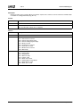
16.0 Virtual Hardware . . . . . . . . . . . . . . . . . . . . . . . . . . . . . . . . . . . . . . . . . . . . . . . . . 237
16.1 Virtual Video . . . . . . . . . . . . . . . . . . . . . . . . . . . . . . . . . . . . . . . . . . . . . . . . . . . . . . . . . . . . . . 237
16.2 Virtual RTC/CMOS . . . . . . . . . . . . . . . . . . . . . . . . . . . . . . . . . . . . . . . . . . . . . . . . . . . . . . . . . 238
17.0 Power Management . . . . . . . . . . . . . . . . . . . . . . . . . . . . . . . . . . . . . . . . . . . . . . . 239
17.1 Power States . . . . . . . . . . . . . . . . . . . . . . . . . . . . . . . . . . . . . . . . . . . . . . . . . . . . . . . . . . . . . . 239
17.2 PM Initialization . . . . . . . . . . . . . . . . . . . . . . . . . . . . . . . . . . . . . . . . . . . . . . . . . . . . . . . . . . . . 240
4
AMD Geode™ GeodeROM Functional Specification
32087C
Contents
18.0 Configuring/Customizing . . . . . . . . . . . . . . . . . . . . . . . . . . . . . . . . . . . . . . . . . . 243
18.1
18.2
18.3
18.4
18.5
18.6
18.7
18.8
18.9
Quick Start . . . . . . . . . . . . . . . . . . . . . . . . . . . . . . . . . . . . . . . . . . . . . . . . . . . . . . . . . . . . . . . . 243
Build Process . . . . . . . . . . . . . . . . . . . . . . . . . . . . . . . . . . . . . . . . . . . . . . . . . . . . . . . . . . . . . . 243
Environment Variable(s) . . . . . . . . . . . . . . . . . . . . . . . . . . . . . . . . . . . . . . . . . . . . . . . . . . . . . . 243
The Configurator . . . . . . . . . . . . . . . . . . . . . . . . . . . . . . . . . . . . . . . . . . . . . . . . . . . . . . . . . . . 243
Build Files . . . . . . . . . . . . . . . . . . . . . . . . . . . . . . . . . . . . . . . . . . . . . . . . . . . . . . . . . . . . . . . . 244
Build Options . . . . . . . . . . . . . . . . . . . . . . . . . . . . . . . . . . . . . . . . . . . . . . . . . . . . . . . . . . . . . . 244
Splash Screen . . . . . . . . . . . . . . . . . . . . . . . . . . . . . . . . . . . . . . . . . . . . . . . . . . . . . . . . . . . . . 244
Summary Screen . . . . . . . . . . . . . . . . . . . . . . . . . . . . . . . . . . . . . . . . . . . . . . . . . . . . . . . . . . . 244
CMOS Setup . . . . . . . . . . . . . . . . . . . . . . . . . . . . . . . . . . . . . . . . . . . . . . . . . . . . . . . . . . . . . . 245
19.0 Debugging . . . . . . . . . . . . . . . . . . . . . . . . . . . . . . . . . . . . . . . . . . . . . . . . . . . . . . 255
19.1 MTEST PINS: . . . . . . . . . . . . . . . . . . . . . . . . . . . . . . . . . . . . . . . . . . . . . . . . . . . . . . . . . . . . . 255
19.2 GPCS# . . . . . . . . . . . . . . . . . . . . . . . . . . . . . . . . . . . . . . . . . . . . . . . . . . . . . . . . . . . . . . . . . . . 255
20.0 Build Utilities . . . . . . . . . . . . . . . . . . . . . . . . . . . . . . . . . . . . . . . . . . . . . . . . . . . . 257
20.1 Custom Build Utilities by AMD . . . . . . . . . . . . . . . . . . . . . . . . . . . . . . . . . . . . . . . . . . . . . . . . . 257
20.2 Off-The-Shelf Build Utilities . . . . . . . . . . . . . . . . . . . . . . . . . . . . . . . . . . . . . . . . . . . . . . . . . . . 262
Appendix A
Revision History . . . . . . . . . . . . . . . . . . . . . . . . . . . . . . . . . . . . . . . . . . 263
AMD Geode™ GeodeROM Functional Specification
5
32087C
6
Contents
AMD Geode™ GeodeROM Functional Specification
List of Figures
32087C
List of Figures
Figure 1-1.
Figure 3-1.
Figure 6-1.
Figure 15-1.
Figure 18-1.
Figure 18-2.
Figure 18-3.
Figure 18-4.
Figure 18-5.
Figure 18-6.
GeodeROM Functionality . . . . . . . . . . . . . . . . . . . . . . . . . . . . . . . . . . . . . . . . . . . . . . . . . . . . 11
Xpress Tree . . . . . . . . . . . . . . . . . . . . . . . . . . . . . . . . . . . . . . . . . . . . . . . . . . . . . . . . . . . . . . 26
System BIOS INT 13h Interface with Enhanced IDE Data Structures . . . . . . . . . . . . . . . . . . 71
VSM Client-Server Model Example . . . . . . . . . . . . . . . . . . . . . . . . . . . . . . . . . . . . . . . . . . . 212
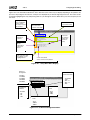
Setup Main Menu Display . . . . . . . . . . . . . . . . . . . . . . . . . . . . . . . . . . . . . . . . . . . . . . . . . . 246
I/O Device Configuration Menu . . . . . . . . . . . . . . . . . . . . . . . . . . . . . . . . . . . . . . . . . . . . . . 246
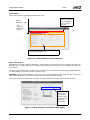
Standard Memory Optimization Menu . . . . . . . . . . . . . . . . . . . . . . . . . . . . . . . . . . . . . . . . . 247
Manual Memory Configuration Menu Display . . . . . . . . . . . . . . . . . . . . . . . . . . . . . . . . . . . 247
TV Output and Configuration Menu . . . . . . . . . . . . . . . . . . . . . . . . . . . . . . . . . . . . . . . . . . . 248
Low Pin Count (LPC) Bus Setup Menu . . . . . . . . . . . . . . . . . . . . . . . . . . . . . . . . . . . . . . . . 248
AMD Geode™ GeodeROM Functional Specification
7
32087C
8
List of Figures
AMD Geode™ GeodeROM Functional Specification
List of Tables
32087C
List of Tables
Table 2-1.
Table 2-2.
Table 5-1.
Table 6-1.
Table 6-2.
Table 6-3.
Table 6-4.
Table 7-1.
Table 7-2.
Table 8-1.
Table 9-1.
Table 10-1.
Table 11-1.
Table 12-1.
Table 12-2.
Table 12-3.
Table 12-4.
Table 13-1.
Table 13-2.
Table 13-3.
Table 13-4.
Table 13-5.
Table 14-1.
Table 15-1.
Table 15-2.
Table 15-3.
Table 15-4.
Table 15-5.
Table 15-6.
Table 15-7.
Table 15-8.
Table 15-9.
Table 16-1.
Table 17-1.
Table 18-1.
Table 20-1.
Table A-1.
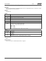
Summary of Supported INTx Functions . . . . . . . . . . . . . . . . . . . . . . . . . . . . . . . . . . . . . . . . . 17
Acronyms and Definitions . . . . . . . . . . . . . . . . . . . . . . . . . . . . . . . . . . . . . . . . . . . . . . . . . . . 24
INT 40h Functions . . . . . . . . . . . . . . . . . . . . . . . . . . . . . . . . . . . . . . . . . . . . . . . . . . . . . . . . . 31
INT 13h Functions . . . . . . . . . . . . . . . . . . . . . . . . . . . . . . . . . . . . . . . . . . . . . . . . . . . . . . . . . 43
info_flag Field . . . . . . . . . . . . . . . . . . . . . . . . . . . . . . . . . . . . . . . . . . . . . . . . . . . . . . . . . . . . . 61
Format of the BIOS Data Area . . . . . . . . . . . . . . . . . . . . . . . . . . . . . . . . . . . . . . . . . . . . . . . . 62
Fixed Disk Parameter Table (FDPT) . . . . . . . . . . . . . . . . . . . . . . . . . . . . . . . . . . . . . . . . . . . 69
INT 1Ah, B1h PCI BIOS Subfunctions . . . . . . . . . . . . . . . . . . . . . . . . . . . . . . . . . . . . . . . . . . 73
AL Register Upon Return From A Successful Call to PCI_BIOS_PRESENT . . . . . . . . . . . . 75
INT 14h Functions . . . . . . . . . . . . . . . . . . . . . . . . . . . . . . . . . . . . . . . . . . . . . . . . . . . . . . . . . 83
INT 17h Functions . . . . . . . . . . . . . . . . . . . . . . . . . . . . . . . . . . . . . . . . . . . . . . . . . . . . . . . . . 87
INT 16h HID Functions . . . . . . . . . . . . . . . . . . . . . . . . . . . . . . . . . . . . . . . . . . . . . . . . . . . . . 89
INT 1Ah Time and Date Functions . . . . . . . . . . . . . . . . . . . . . . . . . . . . . . . . . . . . . . . . . . . . . 95
INT 15h System Services Support Functions . . . . . . . . . . . . . . . . . . . . . . . . . . . . . . . . . . . 101
Global Descriptor Table (GDT) . . . . . . . . . . . . . . . . . . . . . . . . . . . . . . . . . . . . . . . . . . . . . . 128
GDT Descriptor Table Format . . . . . . . . . . . . . . . . . . . . . . . . . . . . . . . . . . . . . . . . . . . . . . . 128
NVRAM Table . . . . . . . . . . . . . . . . . . . . . . . . . . . . . . . . . . . . . . . . . . . . . . . . . . . . . . . . . . . 136
INT 10h Video BIOS Functions . . . . . . . . . . . . . . . . . . . . . . . . . . . . . . . . . . . . . . . . . . . . . . 163
Text Mode Fonts . . . . . . . . . . . . . . . . . . . . . . . . . . . . . . . . . . . . . . . . . . . . . . . . . . . . . . . . . 165
VBE Completion Codes . . . . . . . . . . . . . . . . . . . . . . . . . . . . . . . . . . . . . . . . . . . . . . . . . . . . 192
Supported VBE Functions . . . . . . . . . . . . . . . . . . . . . . . . . . . . . . . . . . . . . . . . . . . . . . . . . . 192
Refresh Rates . . . . . . . . . . . . . . . . . . . . . . . . . . . . . . . . . . . . . . . . . . . . . . . . . . . . . . . . . . . 206
Miscellaneous Software Interrupts . . . . . . . . . . . . . . . . . . . . . . . . . . . . . . . . . . . . . . . . . . . . 209
VSM Types . . . . . . . . . . . . . . . . . . . . . . . . . . . . . . . . . . . . . . . . . . . . . . . . . . . . . . . . . . . . . 217
System Calls . . . . . . . . . . . . . . . . . . . . . . . . . . . . . . . . . . . . . . . . . . . . . . . . . . . . . . . . . . . . 220
Event Registration Parameters . . . . . . . . . . . . . . . . . . . . . . . . . . . . . . . . . . . . . . . . . . . . . . 221
Hardware Supported Traps and Time-outs . . . . . . . . . . . . . . . . . . . . . . . . . . . . . . . . . . . . . 222
Messages . . . . . . . . . . . . . . . . . . . . . . . . . . . . . . . . . . . . . . . . . . . . . . . . . . . . . . . . . . . . . . . 225
Power States . . . . . . . . . . . . . . . . . . . . . . . . . . . . . . . . . . . . . . . . . . . . . . . . . . . . . . . . . . . . 226
Events . . . . . . . . . . . . . . . . . . . . . . . . . . . . . . . . . . . . . . . . . . . . . . . . . . . . . . . . . . . . . . . . . 228
Macros . . . . . . . . . . . . . . . . . . . . . . . . . . . . . . . . . . . . . . . . . . . . . . . . . . . . . . . . . . . . . . . . . 232
Shorthand Macros . . . . . . . . . . . . . . . . . . . . . . . . . . . . . . . . . . . . . . . . . . . . . . . . . . . . . . . . 235
Virtual Video Register . . . . . . . . . . . . . . . . . . . . . . . . . . . . . . . . . . . . . . . . . . . . . . . . . . . . . 237
PM Virtual Registers . . . . . . . . . . . . . . . . . . . . . . . . . . . . . . . . . . . . . . . . . . . . . . . . . . . . . . 240
Setup Navigation Keys . . . . . . . . . . . . . . . . . . . . . . . . . . . . . . . . . . . . . . . . . . . . . . . . . . . . . 245
Information Header Format . . . . . . . . . . . . . . . . . . . . . . . . . . . . . . . . . . . . . . . . . . . . . . . . . 260
Revision History . . . . . . . . . . . . . . . . . . . . . . . . . . . . . . . . . . . . . . . . . . . . . . . . . . . . . . . . . . 263
AMD Geode™ GeodeROM Functional Specification
9
32087C
10
List of Tables
AMD Geode™ GeodeROM Functional Specification
Overview
32087C
1
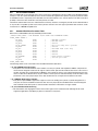
1.0Overview
1.1
Scope
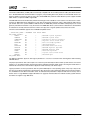
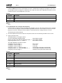
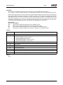
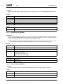
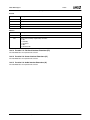
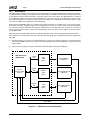
GeodeROM is the firmware for AMD Geode™ solutions. It is a set of components designed to initialize devices, provide
interrupt services, and emulate traditional hardware functionality. GeodeROM is targeted for platform designs using an
AMD Geode™ GX1, AMD Geode™ GX, or AMD Geode™ LX processor and companion device or a single chip processor
(e.g., SC1100, SC1200, SC1201, SC2200, SC3200). Figure 1-1 illustrates the general functionality of GeodeROM.
1.2
General Description
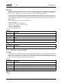
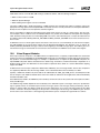
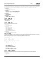
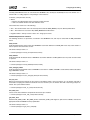
The functional layout depicts the operational components of the GeodeROM Power-On Self Test (POST), as well as other
services. During POST, the Geode devices are initialized along with other devices (such as the SuperI/O) and the SDRAM
is identified, configured, and optimized. This document refers to the GeodeROM System Management Mode (SMM) software as AMD’s VSA2 (Virtual System Architecture™) technology. VSA2 software, including emulated hardware, is decompressed and initialized. System ROMs are included to support other special functionality. There may also be adapter ROMs
present in the system or ROM binaries embedded in the GeodeROM image. These ROMs are decompressed, shadowed,
and initialized. Finally, an operating system is started. GeodeROM also contains some miscellaneous runtime support services.
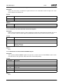
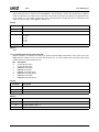
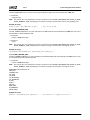
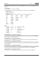
The GeodeROM image consists of POST code, initialization routines, and other features. The initialization code and various runtime services reside in the upper 64 KB of the GeodeROM image. Features such as option ROMs, VSA2 technology, or a splash screen bitmap are compressed. The compressed binary images are pre-padded to 192 KB. The
initialization and support code is concatenated to the 192 KB image.
GeodeROM Functional Layout
GeodeROM Flash Image
256 KB
Initialize AMD Geode™
Solutions
Decompress and
Initialize VSA2 Software
POST
Execution
Flow
Miscellaneous
Runtime
Services
Decompress and
Initialize System ROM
(HDD, FDD, KB Support)
Start
Operating System
GeodeROM
Core Features
Initialization Routines
192 KB
Compressed Images:
- VSA2 Software and VSMs
- Splash Bitmap
- System ROMs
Variable
Padded Free Space
0
Figure 1-1. GeodeROM Functionality
AMD Geode™ GeodeROM Functional Specification
11
32087C
1.3
Overview
Features
GeodeROM provides support to Geode solutions and provides the following initialization and runtime API (application programming interface) support:
■ Legacy Power Management
— GeodeROM provides operating system transparent power management.
■ APM (Advanced Power Management) Real Mode/Protected Mode APIs
— The GeodeROM INT 15h API supports the APM 1.2 functions listed in the “Advanced Power Management (APM)
BIOS Interface Specification” available from Microsoft®, Intel, and other sources.
■ ACPI (Advanced Configuration and Power Interface)
— GeodeROM provides configuration tables and methods necessary to support the ACPI 1.0b specification available
from Microsoft, Intel, and other sources.
■ Boot Menu
— The system designer can install a menu to activate at POST. The menu provides a list of devices or embedded option
ROMs from which to load potential operating systems. It can be especially useful for systems requiring a recovery
mechanism, or may be used for demonstrating various bootstrap options.
■ Build Environment is Embedded in ROM Image
— The GeodeROM Flash image contains an encoded list of all the user-defined options. Additionally, any overridden file
name and version number is also embedded into the ROM image. This provides a means to determine how the
image was created and makes the debugging process easier.
■ Enhanced/Large IDE Detection and Configuration
— Provides a mechanism that identifies and configures ATA devices, such as IDE drives and CompactFlash devices.
During a power-on or reset sequence, GeodeROM scans the primary and secondary IDE channels for ATA compliant
devices. For each ATA device that is present, GeodeROM performs the ATA “Identify” command to determine the
drive’s geometry, capability, and vendor-specific information. The drive and controller timing registers are configured
for optimal performance based on the combination of drives attached to the system. If a drive’s geometry exceeds the
capability of the standard INT 13h interface, GeodeROM performs CHS (Cylinder/Head/Sector) translation to enable
the legacy operating system to utilize the full capacity of the IDE device.
■ Bootable CD-ROM Support:
— Supports bootable CD-ROM drives off of the IDE interface. Floppy emulation formats are supported.
■ INT 11h (Equipment List)
— Provides a traditional INT 11h service (for operating systems) that determines the number and type of installed IBM
PC/AT-style peripherals.
■ INT 12h (Get Memory Size)
— This GeodeROM interrupt reports to drivers, applications, and operating systems, the amount of base (< 640 KB)
memory available in the system. Typically, this interrupt returns the value 639 (KB), representing the lower ten
segments of real mode RAM minus 1 KB that is allocated to an EBDA (Extended BIOS Data Area).
■ INT 13h (1.44 MB Floppy Disk Support)
— Provides support for a 3.5”/1.44 MB floppy disk drive. The GeodeROM INT 13h floppy disk services enable the user
to read, write, format, verify, and boot from a 1.44 MB floppy diskette. Additionally, GeodeROM provides disk change
line support for the floppy disk drive.
■ INT 13h (Fixed Disk Services w/IBM Extensions)
— In addition to the standard IBM PC/AT-style INT 13h interface, GeodeROM implements the fixed-disk subset of those
INT 13h extensions, defined by the “INT 13h Extensions API” IBM document. These extensions enable GeodeROM,
in conjunction with certain operating systems, to support drives whose capacity exceeds 8.4 GB. GeodeROM also
supports LBA (Logical Block Addressing) for devices larger than 8.4 GB.
■ INT 14h (Serial Port BIOS Support)
— Supports the standard INT 14h interface for initializing, reading and writing data from, and checking the status of the
serial port.
12
AMD Geode™ GeodeROM Functional Specification
Overview
32087C
■ INT 15h Functions
— Function 24h (A20 Gate Support)
– Contains functions for enabling, disabling, and querying the status of the A20 Gate.
— Function 87h (Extended Memory Block Move)
– Provides traditional 286 PC/AT-style service to applications, drivers, and operating systems that move blocks of
memory to, from, or within extended RAM while executing in real mode.
— Function 88h (Get Extended Memory Size)
– Provides traditional PC/AT-style service as a means of reporting the amount of installed, extended system DRAM
(up to 64 MB) to the operating system.
— Function 89h (Enter Protected Mode)
– Switches the system into protected mode with support for 286 and higher technology.
— Function BEh (ACCESS.bus and NVRAM Access Method)
– GeodeROM contains AMD-specific BIOS calls for accessing devices on an ACCESS.bus. A caller provides an
ACCESS.bus address and can read or write the device.
– GeodeROM contains AMD-specific BIOS calls for accessing data in NVRAM. The caller is not required to know
details about the location of this data, but may use the predefined tokens to read or write data in NVRAM.
— Function C0h (Get ROM Configuration)
– Returns a pointer to the ROM configuration tables that contains system information such as model, sub-model,
and other features.
— Function C1h (Get EBDA)
– Returns the segment address of the EBDA.
— Function C2h (PS/2 Mouse Support)
– There is optional support for a standard PS/2 mouse in GeodeROM. This is comprised of code to initialize the
mouse, the INT 15h Function C2h calls, and the INT 74h code to handle IRQ 12.
— Function E8h (Memory Size and Memory Map)
– GeodeROM contains support for the E8h functions for determining the system memory size (Function E801h) and
for building a system memory map (Function E820h).
■ INT 16h (IRQ1 Keyboard Services)
— Provides INT 16h keyboard services via a small IBM-style option ROM. GeodeROM also includes an IRQ1 handler to
process incoming scan codes and manage the circular scan code buffer that resides in the BDA (BIOS Data Area). To
support applications and drivers that intercept scan codes, the IRQ1 handler forwards all scan codes to the INT 15h,
Function 4Fh scan code redirect. The keyboard code also supports calling INT 1Bh for Ctrl-Break functionality.
■ INT 17h (Parallel Port BIOS Support)
— Supports the standard INT 17h interface for initializing, getting status, and writing data to the parallel port.
■ INT 1Ah (PCI BIOS INT Support)
— Provides a real mode, INT 1Ah interface to many of the B1h class subfunctions defined in revisions 2.2 and newer of
the PCI BIOS Specification.
■ INT 1Ah (System Time/Date Functions)
— Supports most of the standard functions for setting and viewing the system time and date, as well as setting the
alarm.
■ Companion Device Register Initialization
— Downloads a table of default values into the PCI-ISA bridge portion of the Geode device following a power-on reset.
Subsequent code sequences (e.g., VSA2 software) may change the default values as features are enabled, disabled,
or reconfigured.
■ LCD Panel Initialization
— GeodeROM can configure and enable an LCD flat panel. TFT panels are supported by default. The system designer
selects the panel type and resolution in order to include this support.
AMD Geode™ GeodeROM Functional Specification
13
32087C
Overview
■ Legacy USB
— GeodeROM can be configured to support legacy USB, thereby allowing the use of a USB keyboard and mouse
before a driver is loaded by the operating system. Associated with this functionality is a “virtual keyboard controller”
module, allowing for a standard keyboard BIOS look and feel, in the absence of a keyboard controller.
■ USB Floppy Boot Support:
— Supports booting USB floppy drives in systems without a standard floppy drive.
■ Legacy BIOS Entry Points
— GeodeROM provides the legacy BIOS function entry points for use by legacy software as a compatibility feature.
■ PCI ‘_32_’ Services Directory Table
— Provides a ‘_32_’ bit service directory that provides the operating system information regarding the location of the 32bit PCI BIOS API. Some operating systems use the information in this table to determine the presence and location of
32-bit, flat-mode PCI BIOS services. The ‘_32_’ bit service directory is described in revisions 2.1 and newer of the
PCI BIOS Specification.
■ PCI BIOS 32-Bit Protected Mode API
— Provides a flat-mode, 32-bit protected mode interface to those PCI bus access functions defined in revisions 2.1 and
newer of the PCI BIOS Specification.
■ Power-On Splash Screen (supports .BMP format)
— Contains special sequences of ROM-based code for displaying OEM-supplied splash screens during the power-on
sequence, rather than the traditional text-mode DRAM count and similar displays. The current GeodeROM implementation supports 320x200, 640x480, 800x600, 1024x768, and 1280x1024 .BMP file formats.
■ Power-On Time Option ROM Invocation/Initialization
— Shadows and invokes any option ROMs that adhere to the format specified in documents such as “The IBM PS/2
Model 60 Technical Reference Manual.” Such option ROMs contain a special “55h/AAh” header, size byte, and initialization entry point. GeodeROM searches for and invokes any valid ROMs that reside on 2 KB boundaries in region
C800:0h-DF80:0h. Option ROMs can be found on ISA cards, PCI devices, or be embedded in the GeodeROM image.
■ Power-On Time PCI Enumeration/Configuration
— Automatically detects, initializes, and configures PCI 2.1 compliant devices that appear in PCI configuration space
following a power-on sequence. GeodeROM contains a resource allocation module that assigns I/O, address space,
and IRQ resources to PCI devices, and ensures the resources assigned to the devices are conflict free. GeodeROM
also programs the steering and edge/level values of IRQs assigned to PCI devices during the power-on sequence.
■ Protected Mode Reset
— GeodeROM supports the 286-style reset typically used for returning the microprocessor from protected mode to real
mode. Functions 05h and 0Ah are currently supported. The caller resets the microprocessor by writing the function
value into CMOS location 0Fh and resetting the system.
■ Compression/Decompression for BIOS Modules (Plus Compression Utility)
— Provides developers the capability of storing code and data modules in compressed form within the system Flash or
EEPROM device. Compressed modules contain a header that identifies the type, size, target decompression
segment, compression method, and other information used to build or manipulate the compressed module. During a
power-on or reset sequence, and following DRAM bank configuration, GeodeROM decompresses such modules into
system shadow RAM space. Compression usage has the advantage of conserving build time ROM device space,
enabling developers to include significantly more functionality in a ROM device than would be possible without the
use of compression. A DOS utility is provided that compresses source ROM modules and supplies these modules
with the correct header information.
■ SDRAM Bank Sizing/Geode Processor DRAM Controller Initialization
— Determines the amount of memory installed in the system’s SDRAM banks, configures the processor’s SDRAM
controller with the appropriate row/column information, and initializes the SDRAM timings. If the SDRAM modules
support SPD (Serial Presence Detection) EEPROMs, special GeodeROM code queries the SPD EEPROMs via a
standard ACCESS.bus interface and may optimize the SDRAM timings based on the reported capabilities of a particular SDRAM module.
14
AMD Geode™ GeodeROM Functional Specification
Overview
32087C
■ SMI (System Management Interrupt)-Based Memory Access Capability
— An SMI handler feature useful for debugging in unfamiliar or highly protected environments has the ability to read or
write addressable locations in the system. This is done through a virtual register access.
■ VSA2 Software Initialization
— Contains sequences of code to decompress, load, and invoke the SMI handler. These sequences also initialize SMIspecific registers, such as SMAR (System Management Address Register) SMHR (System Management Header
Register) and GX_BASE. Each is required for successful initialization of the VSA2 software.
■ Summary Screen
— Displays a summary of vital system information (such as hardware found, CPU revision and speed, memory size,
etc.) immediately before starting the operating system.
■ SuperI/O Device Initialization
— The SuperI/O device initialization portion of GeodeROM is a platform-dependent module that initializes the traditional
ISA bus components that reside in the SuperI/O device. For example, in a system that contains National’s PC97317
SuperI/O, this portion of the GeodeROM code configures and assigns resources to the floppy disk controller, serial
COM ports, parallel LPT port, and 8042 keyboard controller.
■ Text-Based Configuration Utility
— The GeodeROM build process includes a series of questions to which the system designer provides information
about the board wiring, options to install, and generally how GeodeROM should behave. The tool runs automatically
the first time the build process takes place and on subsequent builds uses the information from a saved option file
(XPRESCFG.OPT).
■ Virtual Real-Time Clock and CMOS
— The real-time clock (RTC) VSM (VSA2 Modular Component) simulates an RTC, including CMOS for platforms or
designs that do not provide a hardware RTC. While the CMOS and clock states cannot be maintained across a power
loss, a system designer may elect to forego a physical RTC, still allowing many types of software to run effectively.
■ Virtual UART
— The UART VSM simulates the functionality of one or more UARTs. The module provides the look and feel of a standard UART, and has the flexibility for delivering or retrieving data from some hardware sources (e.g., an on-board
microcontroller).
■ CMOS Setup
— GeodeROM setup provides a configurable engine for configuring a target platform.
AMD Geode™ GeodeROM Functional Specification
15
32087C
16
Overview
AMD Geode™ GeodeROM Functional Specification
Introduction
32087C
2
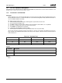
2.0Introduction
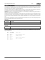
This functional specification discusses supported GeodeROM software interfaces, and use of the GeodeROM source code,
including project builds and current functionality modification. This specification is intended for BIOS, or deployment engineers working on AMD Geode™ solutions.
2.1
Supported INT/Functions
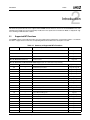
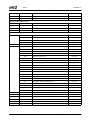
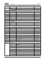
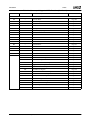
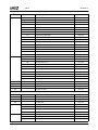
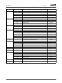
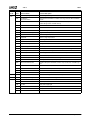
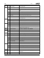
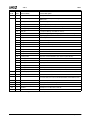
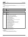
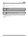
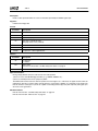
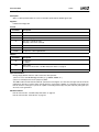
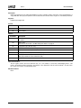
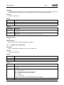
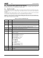
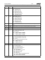
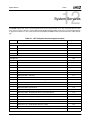
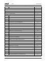
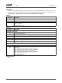
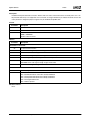
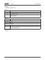
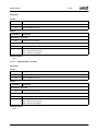
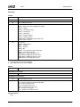
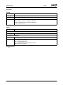
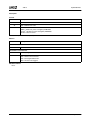
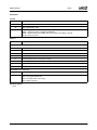
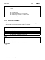
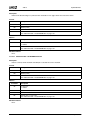
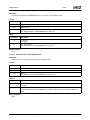
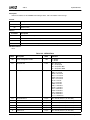
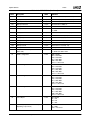
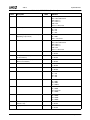
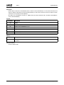
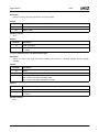
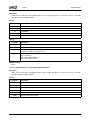
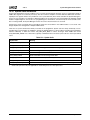
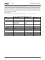
GeodeROM supports several INT instructions and associated functions/subfunctions, summarized in Table 2-1. Included in
the table is a page reference where the corresponding INT/function/subfunction’s description is located.
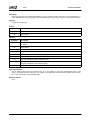
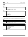
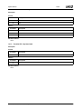
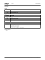
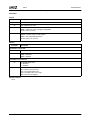
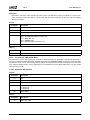
Table 2-1. Summary of Supported INTx Functions
Function
Subfunction
Function Description
Reference
INT 09h: Miscellaneous Service
Keyboard
Page 209
INT 10h: Miscellaneous Service
Video BIOS
Page 209
INT 11h: Miscellaneous Service
Equipment List
Page 210
INT 12h: Miscellaneous Service
Get Memory Size
Page 210
INT 13h: Removable and Non-Removable Media Support (INT 13h and INT 40h Interrupt Handler)
00h
---
Reset Disk Subsystem
Page 32, Page 44
01h
---
Get Disk Subsystem Status
Page 33, Page 46
02h
---
Read Sectors
Page 34, Page 47
03h
---
Write Sectors
Page 35, Page 48
04h
---
Verify Sectors
Page 36, Page 49
05h
---
Format Track (Floppy Disk)
Page 37
08h
---
Get Drive Parameters
Page 38, Page 50
09h
---
Set Drive Parameters
Page 51
0Ch
---
Seek To Cylinder
Page 52
0Dh
---
Alternate Disk Subsystem Reset
10h
---
Test Drive Ready
Page 53
11h
---
Recalibrate Drive
Page 54
14h
---
Perform Disk Self-Diagnostic
Page 54
15h
---
Get Disk Type
Page 39, Page 53
Page 39, Page 55
16h
---
Get Disk Change Status
Page 40
17h
---
Set Disk Type
Page 41
18h
---
Set Media Type
Page 42
41h
---
Check Extensions Present
Page 57
42h
---
Extended Read Sectors
Page 58
43h
---
Extended Write Sectors
Page 58
44h
---
Extended Verify Sectors
Page 59
AMD Geode™ GeodeROM Functional Specification
17
32087C
Introduction
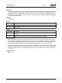
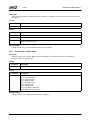
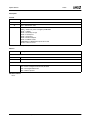
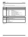
Table 2-1. Summary of Supported INTx Functions (Continued)
Function
Subfunction
Function Description
Reference
47h
---
Extended Seek To Cylinder
Page 59
48h
---
Extended Get Drive Parameters
Page 60
INT 14h: Serial Port BIOS Support
00h
---
Initialize Port
Page 83
01h
---
Write Character to Port
Page 85
02h
---
Read Character from Port
Page 85
03h
---
Get Port Status
Page 86
Disable A20 Gate
Page 103
01h
Enable A20 Gate
Page 104
02h
Get A20 Gate Status
Page 104
03h
A20 Support
Page 105
Key Scan Hook
Page 105
INT 15h: System Service Support
24h
4Fh
53h
18
00h
--00h
APM Installation Check
Page 106
01h
APM Real Mode Interface Connect
Page 107
02h
APM Protected Mode 16-Bit Interface Connect
Page 108
03h
APM Protected Mode 32-Bit Interface Connect
Page 108
04h
APM Interface Disconnect
Page 109
05h
CPU Idle
Page 110
06h
CPU Busy
Page 111
07h
Set Power State
Page 112
08h
Enable/Disable Power Management
Page 113
09h
Restore APM BIOS Power-On
Page 114
0Ah
Get Power Status
Page 115
0Bh
Get PM Event
Page 116
0Ch
Get Power State
Page 117
0Dh
Enable/Disable Device Power Management
Page 118
0Eh
APM Driver Version
Page 119
0Fh
Engage/Disengage Power Management
Page 120
10h
Get Capabilities
Page 121
11h
Get/Set/Disable Resume Timer
Page 122
12h
Enable/Disable Resume on Ring
Page 123
13h
Enable/Disable TImer Based Requests
Page 124
86h
---
BIOS Wait
Page 125
87h
---
Extended Memory Block Move
Page 126
88h
---
Get Extended Memory Size
Page 127
89h
---
Enter Protected Mode
Page 127
90h
---
Device Busy
Page 128
91h
---
Interrupt Complete
Page 129
AMD Geode™ GeodeROM Functional Specification
32087C
Introduction
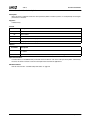
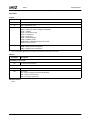
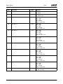
Table 2-1. Summary of Supported INTx Functions (Continued)
Function
Subfunction
BEh
C0h
Function Description
Reference
00h
Read ACCESS.bus Byte
Page 131
01h
Write ACCESS.bus Byte
Page 132
02h
Write ACCESS.bus Block
Page 132
03h
Read NVRAM Data
Page 132
04h
Write NVRAM Data
Page 133
05h
Get Default NVRAM Value
Page 134
06h
Get NVRAM Checksum
Page 134
07h
Set NVRAM Checksum
Page 135
08h
Reset NVRAM Default
Page 135
09h
Get NVRAM Table Address
Page 136
0Ah
ACCESS.bus Block Read
Page 142
20h
Get SCxxxx External Clock Speed
Page 143
21h
Get SCxxxx Device Type
Page 143
31h
SCxxxx Read ACCESS.bus Device
Page 144
32h
SCxxxx Write ACCESS.bus Device
Page 144
35h
Owl Board Specific Feature Access
Page 145
A0h
Wait for Key Timeout
Page 146
A1h
Get ROM Data
Page 147
A2h
CPU Memory Register Read Int
Page 148
A3h
CPU Memory Register Write Int
Page 148
A4h
Get CPU Speed
Page 149
A5h
Check CMOS
Page 149
A6h
Check CMOS Power
Page 150
A7h
Get PCI Speed
Page 150
A8h
Set Warning
Page 151
A9h
Read Companion Chip DWORD
Page 151
AAh
CPU Register Read
Page 152
ABh
CPU Register Write
Page 152
ACh
Eat Key
Page 153
B0h
Get Shadow
Page 153
B1h
Set Shadow
Page 154
F0h-FFh
User Defined Interrupts
Page 154
---
Get ROM Configuration
Page 155
C1h
---
Get EBDA Address
Page 155
C2h
00h
Enable/Disable Pointing Device
Page 156
01h
Reset Pointing Device
Page 157
02h
Set Sample Rate
Page 157
03h
Set Resolution
Page 158
04h
Read Device Type
Page 158
05h
Initialize Pointing Device Interface
Page 159
06h
Pointing Device Extended Commands
Page 159
07h
Set Pointing Device Handler Address
Page 160
AMD Geode™ GeodeROM Functional Specification
19
32087C
Introduction
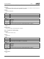
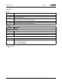
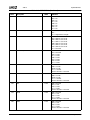
Table 2-1. Summary of Supported INTx Functions (Continued)
Function
Subfunction
Function Description
Reference
E8h
01h
Get System Memory Size
Page 160
20h
Get System Memory Map
Page 161
INT 16h: Human Interface Device Support
00h
---
Wait For Character
Page 89
01h
---
Check For Key Present
Page 90
02h
---
03h
Get Shift Status
Page 90
Set Keyboard Typematic Rate
Page 91
05h
---
Insert Key Code In Keyboard Buffer
Page 91
10h
---
Get Extended Key Code
Page 92
11h
---
Check For Enhanced Key Code
Page 92
12h
---
Get Extended Shift Status
Page 93
Print a Character
Page 87
INT 17h Parallel Port BIOS Support
00h
---
01h
---
Initialize Parallel Port
Page 88
02h
---
Get Port Status
Page 88
INT 1Ah: System Time and Date Support
00h
---
Get System Time Status
Page 95
01h
---
Set System Time
Page 96
02h
---
Get Real-Time Clock Time Status
Page 96
03h
---
Set Real-Time Clock Time
Page 97
04h
---
Get Real-Time Clock Date Status
Page 97
05h
---
Set Real-Time Clock Date
Page 98
06h
---
Set Real-Time Clock Alarm
Page 98
07h
---
Cancel Real-Time Clock Alarm
Page 98
09h
---
Get Real-Time Clock Alarm Status
Page 99
0Ah
---
Read System Day Counter
Page 99
0Bh
---
Set System Day Counter
Page 99
0Eh
---
Get Real-Time Clock Date/Time Alarm and Status
Page 100
0Fh
---
Initialize Real-Time Clock
Page 100
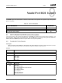
01h
PCI BIOS Present
Page 75
02h
Find PCI Device
Page 76
03h
Find PCI Class Code
Page 77
06h
Generate Special Cycle
Page 78
08h
Read Config BYTE
Page 79
09h
Read Config WORD
Page 80
0Ah
Read Config DWORD
Page 80
INT 1Ah: PCI BIOS Support
B1h
20
0Bh
Write Config BYTE
Page 81
0Ch
Write Config WORD
Page 81
0Dh
Write Config DWORD
Page 82
0Eh
Get PCI Interrupt Routing Options
Page 82
AMD Geode™ GeodeROM Functional Specification
32087C
Introduction
Table 2-1. Summary of Supported INTx Functions (Continued)
Function
Subfunction
Function Description
Reference
INT 6Dh: Video BIOS
00h
---
Set Video Mode
Page 165
01h
---
Set Cursor Type
Page 166
02h
---
Set Cursor Position
Page 166
03h
---
Get Cursor Position
Page 167
04h
---
Read Light Pen
Page 167
05h
---
Set Active Display Page
Page 168
06h
---
Scroll Up
Page 168
07h
---
Scroll Down
Page 169
08h
---
Read Character
Page 169
09h
---
Write Character Attribute
Page 170
0Ah
---
Write Character
Page 170
0Bh
---
Set CGA Palette
Page 171
0Ch
---
Write DOT
Page 171
0Dh
---
Read DOT
Page 172
0Eh
---
Write TTY
Page 172
0Fh
---
Get Mode
Page 173
10h
Palette Handler
Page 173
00h
---
Set Individual Palette Register
Page 173
01h
Set Overscan Register
Page 173
02h
Set All Palette and Overscan Registers
Page 174
03h
Toggle Intensity/Blinking Bit
Page 174
07h
Read Individual Palette Register
Page 174
08h
Read Overscan Register
Page 175
09h
Read All Palette and Overscan Registers
Page 175
10h
Read Individual RAMDAC Register
Page 175
12h
Set Block of RAMDAC Registers
Page 176
13h
Select Color Page
Page 176
15h
Get Individual RAMDAC Register
Page 176
17h
Get Block of RAMDAC Registers
Page 177
1Ah
Get Color PAge
Page 177
1Bh
Sum RAMDAC to Gray Scale
Page 178
AMD Geode™ GeodeROM Functional Specification
21
32087C
Introduction
Table 2-1. Summary of Supported INTx Functions (Continued)
Function
Subfunction
11h
---
12h
Function Description
Reference
Font Handler
Page 178
00h
Load User Font
Page 178
01h
Load 8x14 Font
Page 179
02h
Load 8x8 Font
Page 179
03h
Set Font Block
Page 179
04h
Load 8x16 Font
Page 180
10h
Load User Font with Fixup
Page 180
11h
Load 8x14 Font with Fixup
Page 181
12h
Load 8x8 Font with Fixup
Page 181
14h
Load 8x16 Font with Fixup
Page 181
20h
Load Upper 8x8 Graphics Character Set
Page 182
21h
Load User Graphics Character Set
Page 182
22h
Load 8x14 Graphics Character Set
Page 183
23h
Load 8x8 Graphics Character Set
Page 183
24h
Load 8x16 Graphics Character Set
Page 184
30h
Get Font Information
Page 184
Video Subsystem Configuration (EGA/VGA)
Page 185
10h
Return Video Information
Page 185
20h
Alternate Print Screen
Page 185
30h
Select Scan Lines
Page 186
31h
Enable/Disable Palette Loading
Page 186
32h
Enable/Disable Video Subsystem
Page 187
33h
Enable/Disable Summing to Gray Scales
Page 187
34h
Enable/Disable Cursor Emulation
Page 187
35h
Display Switch
Page 188
36h
---
Enable/Disable Video Screen
Page 188
13h
---
Write String
Page 189
1Ah
---
Get DCC Information
Page 190
1Bh
---
Get Functionality Information
Page 191
1Ch
---
Save/Restore State
Page 191
00h
---
Return VBE Controller Information
Page 193
01h
---
Return VBE Mode Information
Page 194
02h
---
Set VBE Mode
Page 194
03h
---
Get VBE Mode
Page 194
04h
---
VBE Save/Restore State
Page 195
00h
Return Buffer Size in BX
Page 195
01h
Save State
Page 195
02h
Restore State
Page 196
VBE Set/Get Bank
Page 196
00h
Set Bank
Page 196
01h
Get Bank
Page 197
VESA BIOS Extensions
05h
22
---
AMD Geode™ GeodeROM Functional Specification
32087C
Introduction
Table 2-1. Summary of Supported INTx Functions (Continued)
Function
Subfunction
06h
---
07h
08h
09h
Function Description
Reference
VBE Set/Get Logical Scan Line Length
Page 197
00h
Set Scan Line Length in Pixels
Page 197
01h
Get Scan Line Length
Page 197
02h
Set Scan Line Length in Bytes
Page 198
03h
Get Maximum Scan Line Length
Page 198
VBE Set/Get Display Start
Page 199
00h
---
Set Display Start
Page 199
01h
Get Display Start
Page 199
80h
Set Display Start During Vertical Retrace
Page 199
VBE Set/Get RAMDAC Palette Format
Page 200
00h
---
Set Format
Page 200
01h
Get Format
Page 200
VBE Set/Get RAMDAC Palette Data
Page 201
--00h
Set RAMDAC Data
Page 201
01h
Get RAMDAC Data
Page 201
02h
Set Secondary RAMDAC Data
Page 202
03h
Get Secondary RAMDAC Data
Page 202
80h
Set RAMDAC Data During Vertical Retrace with Blanking Enabled
Page 202
0Ah
---
Return VBE Protected Mode Information
Page 203
10h
---
VBE Display Power Management Signaling
Page 204
00h
Version Number/Supported Power State
Page 204
01h
Requested Power State
Page 204
02h
Controller’s Currently Requested Power State
Page 205
11h
---
Flat Panel Interface Extensions (FP)
Page 205
12h
---
Cursor Interface Extensions (CI)
Page 205
13h
---
Audio Interface Extensions (AI)
Page 205
14h
---
OEM Extensions
Page 206
00h
Refresh Rate Select
Page 206
02h
Set Display Enable
Page 206
03h
Set Fixed Timings
Page 207
07h
Get Version Numbers
Page 207
15h
---
VBE Display Data Channel (DDC)
Page 208
16h
---
Graphics System Configuration (GC)
Page 208
AMD Geode™ GeodeROM Functional Specification
23
32087C
2.2
Introduction
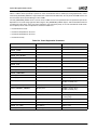
Acronyms and Definitions
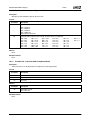
This specification uses several acronyms. Table 2-2 lists, in alphabetical order, the acronyms and their definitions.
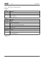
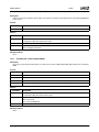
Table 2-2. Acronyms and Definitions
Acronym
Definition
API
Application Programming Interface
APM
Advanced Power Management
BDA
BIOS Data Area
BIOS
Basic I/O System
CHS
Cylinder/Head/Sector
EBDA
Extended BIOS Data Area
HID
Human Interface Device
LBA
Large Block Address
OEM
Original Equipment Manufacturer
PM
Power Management
POST
Power-On Self Test
SIO
SuperI/O
SMAR
System Management Address Register
SMHR
System Management Header Register
SMI
System Management Interrupt
SMM
System Management Mode
SoftVGA
SMI-based handler in the AMD Geode GX1 processor
SoftVG
SMI-based handler in the AMD Geode GX processors*
TSR
Terminate, Stay Resident
VSA
Virtual System Architecture™
VSM
Virtual Support Module
24
AMD Geode™ GeodeROM Functional Specification
Code Structure
32087C
3
3.0Code Structure
The following subsections discuss the GeodeROM directory structure.
3.1
User Directory
All project-specific files are stored in the user directory. The default user directory is XPRESS\USER, but it is not recommended as a project user directory. Rather a separate subdirectory outside the Xpress tree should be made to hold the
user directories. A sample makefile is included in the XPRESS\USER directory.
A sample project user directory structure is as follows:
XPRESS\
PROJECTS\PROJ1
\PROJ2
The files typically found in the user directory are:
• Makefile - The makefile establishes the build environment, then calls the master makefile.
• Splash.bmp - A standard Microsoft® Windows® bitmap file used if splash screen support is needed.
• Userrule.mak - Any additional components that need to be compiled may be added here.
• Xromcfg.opt - The configurator save file for the project.
• User option ROMS
• Overrides
AMD Geode™ GeodeROM Functional Specification
25
32087C
3.2
Code Structure
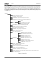
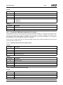
Overrides
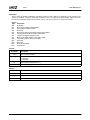
Any source file (.asm) in the build may be overridden by copying the file into the user directory or the project directory.
When GeodeROM is rebuilt, the copy of the file in one of these directories is used instead of the copy in the Xpress tree.
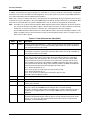
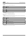
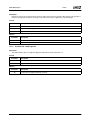
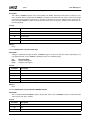
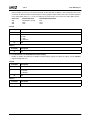
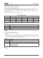
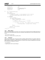
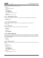
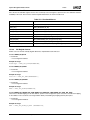
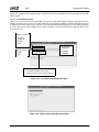
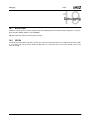
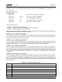
Figure 3-1 depicts the GeodeROM core. The SMI handler may be overridden by files VSA.ROM or VSA2.ROM copied into
the user directory. This allows easy changes on a project-by-project basis. Any files needing changes for a project should
be changed this way. Editing the files in the Xpress tree is discouraged as it creates problems when upgrading to a new
GeodeROM release.
XPRESS\
CACHE - initialization and control
CHIPSET - read/write routines
COMPRESS - compression/decompression functions
CONGFIGS - miscellaneous files used by the build process
GXM
CPU
initialization and register access routines
SC1200, SC2200, SC3200
INCLUDE.INC - files for GeodeROM (except SMM)
INTSRV - interrupt vector table(s) and handlers
LIB - directory used in build process
MEMORY - sizing, settings, and optimization
MISC - catch-all for other source
PCI - device initialization
BOOTOS - bootloader option ROM
(Microsoft® Windows® CE kernal load)
BOOTROM - hard disk services
FLOPROM - floppy disk services
ROMS\SRC
KBDROM - keyboard/mouse services
PCIROM - 32-bit PCI services
BCDROM - bootable CD-ROM functionality
SUMMSCRN - summary screen
SETUP - NVRAM configuration engine
SIO - SuperI/O initialization
TESTS - can optionally be included in GeodeROM
UTILS - tools used in the build process
VECTOR - compatibility vectors and entry points
VIDEO - initialization code for VGA, LCD, companion devices, and the summary screen
VSA - SMM initialization
Figure 3-1. Xpress Tree
26
AMD Geode™ GeodeROM Functional Specification
POST
32087C
4
4.0POST
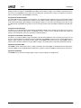
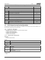
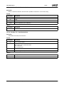
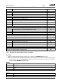
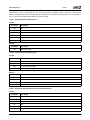
This section outlines the POST (Power-On Self Test) execution flow for GeodeROM, along with the associated checkpoints
that are sent to I/O Port 80h. POST is executed out of xpress.asm. The basic numbering scheme is as follows:
• Reset - 69h, 71h
• Core functions - Numbered in chronological order, starting at 00h
• User functions - 80h and 81h
• Intermediate checkpoints - Numbered in chronological order, beginning on a 10h boundary
• Failing tests - Numbered with xFh and the system halts
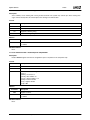
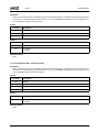
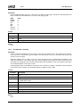
4.1
Post Codes
Post
Code
Sub
Code
F0h
F0h
80h
---
Function Name
Function Description
Reset Vector
Output just prior to a jump to startTest.
startTest/UserPreInit
Just after startTest. Beginning of POST proper. User-added code to be run
first.
startTest/preSioInit
Contains board-specific code to initialize SuperI/O (SIO).
60h
preSioInit
Entering SIO code.
61h
preSioInit
6Bh
preSioInit
Invalid SIO response - try again.
startTest/clockInit
Chipset level clock initialize.
24h
clockInit
After preparing the memory mapped configuration base of the system clock
control registers.
25h
clockInit
After setting up UNREAL mode (ES and FS set to 4 GB flat selectors).
26h
clockInit
After checking if the clock is already setup (getting this code indicates the
clock was not already setup).
27h
clockInit
After inhibiting writes to CX5520_CLK_CTRL0 and loading values from
CX5520_SCLK and CS5520_SCLK_CTRL0.
00h
01h
---
28h
clockInit
Before entering the clock programming loop.
30h
clockInit
End of one iteration through the clock programming loop.
37h
clockInit
Reset pressed; entering infinite loop.
E1h
clockInit
Entering clockInit; see if block is already configured.
E2h
clockInit
Put configuration block on new address.
E3h
clockInit
Start Timer 1 and exit.
AMD Geode™ GeodeROM Functional Specification
27
32087C
Post
Code
Sub
Code
02h1
---
03h
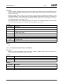
28
POST
Function Name
Function Description
startTest/cpuRegInit
CPU configuration registers initialize.
A9h
UserCpuInit/
RestoreFromRam
Entering RestoreFromRam. Invalidate cache tags and clear GPE and PM1A
events.
AAh
RestoreFromRam
Clear ACPU_BIOS_ST event, set GPWIO0 active-low, prepare GPWIOs,
enable SCI generation and RTC wakeup.
ABh
RestoreFromRam/memResume
Call memResume.
ACh
memResume
Enter memResume.
ADh
memResume
Done restoring memory controllers; enable DIMMs.
E0h
RestoreFromRam/chipsetInit
Begin initialization process.
E1h
chipsetInit
Start of a single loop iteration.
E2h
chipsetInit
End of a single loop iteration.
E8h
chipsetInit/LPCBusInit
LPC Bridge initialization.
EAh
chipsetInit/GPIOInit
GPIOs initialization.
2Ch
chipsetInit/ConfigBaseAddr
Configuration base address is invalid. HLT.
2Dh
chipsetInit/Id_CPU
Invalid crystal in use. HLT.
B1h
RestoreFromRam/GoToSleep
Enter S3V (take memory out of self-refresh, put CPU to sleep).
AFh
GoToSleep
Interrupts cleared; setting 1 sec. RTC alarm.
A3h
GoToSleep
Alarm set; generate and clear SMI so CPU will Suspend.
BDh
RestoreFromRam
Check for memory restore.
B2h
RestoreFromRam
Memory is on; set Bus Interface Unit registers to known.
B3h
RestoreFromRam
Running from RAM; setup a temporary stack.
D4h
RestoreFromRam/IcdInit
Initialize LCD panel and DSTN controller, setup scratch pad, clear SMI registers.
B4h
RestoreFromRam
Should not execute - software should be in SMM.
BFh
RestoreFromRam
Cause software SMI (resume to SMM).
84h
RestoreFromRam
Should not execute - software should be in SMM.
83h
RestoreFromRam
Should not execute - software should be in SMM.
startTest/unReal
Precedes creating a 32-bit real mode descriptors in ES and FS.
---
04h
---
startTest/cpuMemRegInit
Initializes memory controller registers.
05h
---
startTest/clockInit
Geode CPU tests.
20h
clockInit
Test entry.
28h
clockInit
Verify CPU stepping ID.
2Ah
clockInit
Verify CPU feature flags.
2Eh
clockInit
Test passed. Exit.
2Fh
clockInit
Test failed. HLT.
AMD Geode™ GeodeROM Functional Specification
32087C
POST
Post
Code
Sub
Code
06h
---
07h
08h
Function Name
Function Description
startTest/memSetup
Autosize memory controller DIMM1 and DIMM0.
70h
memSetup
Set the clock drive strength and shift value. Mask the clocks.
72h
memSetup
Set the data, address, and control drive. Clear reference timer and VGA
wrap.
73h
memSetup
Initialize register; no DIMMs installed.
74h
memSetup
Initialize CAS latency.
75h
memSetup
Begin sizing DIMMs.
76h
memSetup
Memory Controller enable and perform refresh.
7E
memSetup
MemSetup complete. Exit
7Fh
memSetup
memSetup error. Enable the DIMMs and begin an infinite loop toggling all the
data and address lines.
startTest/memSetUpStack
Set up a stack.
90h
memSetUpStack
Beginning to create the stack.
9Eh
memSetUpStack
Stack creation succeeded. Exit.
9Fh
memSetUpStack
Stack creation failure. HLT.
startTest/memTest
Test memory address lines.
B0h
memTest
Begin testing memory.
BEh
memTest
Memory test succeeded. Exit.
BFh
memTest
Memory test failed. Enable the DIMMs and begin an infinite diagnostic loop
toggling all the data and address lines.
---
---
09h
---
startTest/shadowRom
Copy ROM from F000:0000h to RAM at F000:0000h.
0Ah
---
startTest/PCIDelay
Delay between PCIRST# and first configuration cycle.
0Bh
---
startTest/cacheInit
Test and initialize cache.
cacheInit
Cache initialization failure. HLT.
CFh
0Ch
---
startTest/northBridgeInit
Initialize North Bridge.
northBridgeInit
Begin North Bridge register initialization.
startTest/chipsetInit
Load Geode South Bridge with values.
E0h
chipsetInit
Begin initialization process.
E1h
chipsetInit
Start of a single loop interation.
E2h
chipsetInit
End of a single loop iteration.
E8h
chipsetInit/LPCBusInit
LPC Bridge initialization.
EAh
chipsetInit/GPIOInit
GPIOs initialization.
2Ch
chipsetInit/ConfigBaseAddr
Configuration base address is invalid. HLT.
2Dh
chipsetInit/Id_CPU
Invalid crystal in use. HLT.
startTest/sioTest
SIO test/initialize.
sioTest
SIO test entry.
E8h
0Dh
0Eh
---
--60h
61h
sioTest
SIO present/register initialize (not SP1SC10 or SP4SC40 boards).
6Ah
sioTest
ACCESS.bus initialize (SP1SC10 and SP4SC40 boards).
6Eh
sioTest
SIO test exit.
0Fh
---
startTest/pcATjunk
Initialize Timer 1, DMA, low 640 KB (including stack), and 2nd MB of RAM.
10h
---
startTest/intTable
Initialize interrupt table and timer to 18.2 tics/sec. (also clears equipment list
in itable.asm).
startTest/BDAInit
Initialize the BIOS Data Area (BDA) and XBDA.
startTest/memInfo
Query memory controller for RAM size, and store it.
16h
11h
---
AMD Geode™ GeodeROM Functional Specification
29
32087C
Post
Code
Sub
Code
14h
12h
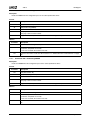
1.
30
POST
Function Name
Function Description
---
keyboardInit
Wakeup the keyboard controller.
---
startTest/romCopy
Initialize the Soft A20, power management, SMI handler, and virtual audio
SMM system.
D0h
romCopy
Enter ROM copy routine.
D1h
romCopy
Begin image decompress loop.
D2h
romCopy
Call VSA/SMM initialization code. Virtual register initialization.
10h
romCopy/VSA_Init
Begin VSA initialization.
11h
VSA_Init
Load System Manager and VSMs into memory.
12h
LoadVSA
System Manager image found. Applying patches to System Manager.
14h
CopyModule
Begin copying module.
15h
CopyModule
Module copy succeeded and another VSM was found.
16h
VSA_Init
Back from loading VSMs.
17h
VSA_Init
Back from cleanup.
18h
VSA_Init
Back from software SMI (initialized VSA).
19h
VSA_Init
Go enable SMI.
1Ah
VSA_Init
Back (enabled SMI).
1Bh
VSA_Init
Return to BIOS.
EEH
VSA_Init
VSA installation/setup error.
14h
romCopy/IcdInit
Keyboard controller initialization (then clear the keyboard buffer).
D3h
romCopy
Initialize VGA BIOS.
D4h
romCopy/IcdInit
Initialize LCD panel and DSTN controller.
D5h
romCopy
Display splash screen.
D6h
romCopy
Hard disk drive initialize.
D7h
romCopy
System option ROM scan and initialize/PCI32 fixup.
DEh
romCopy
Set ROM addresses (C0000h-C7FFFh) for read only access. romCopy exit.
Additional BDA initialization.
82h
---
startTest/equip-check
17h
---
startTest/pciScan
Scan PCI bus and display to screen.
18h
---
startTest/userRomInit
User added (or board-specific) code to prepare for ROM scan. Simply returns
for most boards; active code for SP1SC10, SP4SC30, and SP4SC31 boards.
19h
---
startTest/ResetLimits
Reset all descriptors to real mode 1 MB size.
81h
---
startTest/UserPostInit
Board-specific code to be run right before boot.
1Ah
---
startTest/summary_screen
Display summary screen.
1Bh
---
startTest
Attempt to boot via INT 19h then INT 18h.
1Fh
---
---
Boot failure - GeodeROM halted.
Subcodes between bold lines apply to Restore-From-RAM only.
AMD Geode™ GeodeROM Functional Specification
Removable Media
32087C
5
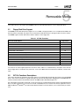
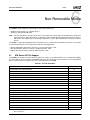
5.0Removable Media
This chapter discusses the support GeodeROM provides for removable media devices, such as floppy disk drives.
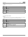
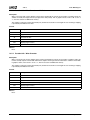
5.1
Floppy Disk Drive Support
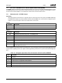
GeodeROM provides INT 40h and boot support for one 1.44 MB, 3.5” floppy disk drive. As in a traditional boot ROM, only
device 0 (A: drive) is bootable. The proper access method for the INT 40h functions is through the INT 13h service routines.
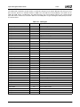
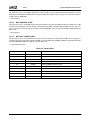
GeodeROM supports the INT 40h functions listed in Table 5-1 for the floppy drive:
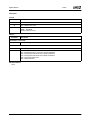
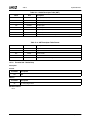
Table 5-1. INT 40h Functions
Function Number/Name
Function 00h - Reset Disk Subsystem
Page Number
32
Function 01h - Get Disk Subsystem Status
33
Function 02h - Read Sectors
34
Function 03h - Write Sectors
35
Function 04h - Verify Sectors
36
Function 05h - Format Track (Floppy Disk)
37
Function 08h - Get Drive Parameters
38
Function 0Dh - Alternate Disk Subsystem Reset
39
Function 15h - Get Disk Type
39
Function 16h - Get Disk Change Status
40
Function 17h - Set Disk Type
41
Function 18h - Set Media Type
42
The format of the caller-supplied parameters and return values adheres to standard industry descriptions of the INT 13h
API for floppy drives as outlined in many references, such as the “IBM PC/AT Technical Reference Manual”, and “PC Interrupts”.
5.2
INT 13h Functions Descriptions
This section describes the parameters and return values for each floppy disk-specific INT 13h function in the GeodeROM
device. This section is intended as a guide. Developers interested in extending and/or debugging the GeodeROM INT 13h
interface should consult the documentation listed on the AMD Geode™ Developer Support site.
INT 13h provides the operating system with a series of functions for communicating with the system’s fixed and floppy disk
drives. The INT 13h interface is a cornerstone of PC/AT compatibility because it ensures that software applications such as
DOS and Microsoft® Windows® can read and write disk-based data in a uniform fashion, across a broad variety of architectures.
AMD Geode™ GeodeROM Functional Specification
31
32087C
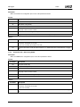
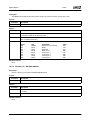
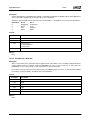
5.2.1
Removable Media
Function 00h - Reset Disk Subsystem
Description:
In an ATA drive-equipped system, this function toggles bit four, in register six, of the Control Register Block. This
causes the disk(s) to recalibrate internally and seek to cylinder zero.
Supports:
Fixed disks and floppy disks.
Passed:
Parameter
Description
AH
00h
DL
Drive number
Returns:
Parameter
Description
CF
0 = Success
1 = Failure
AH
Status code:
00h = Operation completed successfully (fixed, floppy)
01h = Illegal/unrecognized command (fixed, floppy)
02h = Sector address mark not found (fixed, floppy)
03h = Attempt to write to write-protected disk (fixed, floppy)
04h = Sector not found (fixed, floppy)
05h = Reset failure (fixed only)
06h = Diskette change signal (floppy only)
07h = Parameter activity failed (fixed only)
08h = DMA overrun (floppy only)
09h = DMA operation would have crossed a 64 KB boundary (floppy only)
0Ah = Bad or invalid sector (fixed only)
0Bh = Bad or invalid cylinder (fixed only)
0Ch = Invalid cylinder number (fixed only)
0Dh = Invalid number of sectors supplied during format (fixed only)
0Eh = Controller detected control data address mark (fixed only)
0Fh = DMA arbitration failure (fixed only)
10h = CRC/ECC bad (fixed only)
11h = Data corrected using ECC (fixed only)
20h = Controller failed self test (fixed only)
40h = Error during seek (fixed only)
80h = Command timed out (fixed only)
AAh = Drive not ready (fixed only)
BBh = Unknown error (fixed only)
CCh = Write error (fixed only)
E0h = Status register error (fixed only)
FFh = Media sense failed (fixed only)
Special Instructions:
If DL < 80h, both the fixed disks and floppy disks reset.
Related Functions:
INT 13h "Function 01h - Get Disk Subsystem Status" on page 33.
INT 13h "Function 0Dh - Alternate Disk Subsystem Reset" on page 39.
32
AMD Geode™ GeodeROM Functional Specification
32087C
Removable Media
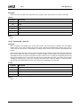
5.2.2
Function 01h - Get Disk Subsystem Status
Description:
Returns the status of the last disk operation in the AH register.
Supports:
Fixed disks and floppy disks.
Passed:
Parameter
Description
AH
01h
DL
Drive number
Returns:
Parameter
AH
Description
Status of the last disk operation:
See AH in "Function 00h - Reset Disk Subsystem" on page 32
Special Instructions:
The system BIOS stores the status of the last fixed disk operation in location 40:74h in the BDA. The preferable
method for retrieving disk status is the INT 13h interface, that enables system software, other than the system BIOS, to
provide accurate disk subsystem status.
Related Functions:
None.
AMD Geode™ GeodeROM Functional Specification
33
32087C
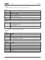
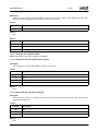
5.2.3
Removable Media
Function 02h - Read Sectors
Description:
Reads a caller-specified number of sectors in the buffer specified by the ES:BX register pair.
Supports:
Fixed disk and floppy disk.
Passed:
Parameter
Description
AH
02h
AL
Sector count
CH
Cylinder bits [7:0]
CL
Bits [7:6] = Cylinder bits [9:8]
Bits [5:0] = Start sector (1-based)
DH
Drive head
DL
Drive number
ES:BX
Far pointer to caller-supplied buffer
Returns:
Parameter
Description
CF
0 = Success
1 = Failure
AH
Status code:
See AH in "Function 01h - Get Disk Subsystem Status" on page 33
AL
Total number of sectors read
Special Instructions:
During a floppy diskette read, the caller ensures the read operation:
1) Does not cross a 64 KB DMA page boundary (e.g., 2000:0h, 3000:0h, etc.).
2) Does not extend past the end of a physical cylinder.
The IBM PC/AT technical reference manual specifies the head register as a 4-bit value; the upper four bits of DH are
undefined on this type of system. Newer systems allow for a head value of 0-0FFh, or a maximum of 255 heads. The
INT 13h functions in this type of system are capable of translating between physical (drive reported) and logical cylinder, head, sector geometries.
Related Functions:
INT 13h "Function 01h - Get Disk Subsystem Status" on page 33.
INT 13h "Function 03h - Write Sectors" on page 35.
34
AMD Geode™ GeodeROM Functional Specification
32087C
Removable Media
5.2.4
Function 03h - Write Sectors
Description:
Writes a caller-specified number of sectors in the buffer specified by the ES:BX register pair.
Supports:
Fixed disk and floppy disk.
Passed:
Parameter
Description
AH
03h
AL
Sector count
CH
Cylinder bits [7:0]
CL
Bits [7:6] = Cylinder bits [9:8]
Bits [5:0] = Start sector (1-based)
DH
Drive head
DL
Drive number
ES:BX
Far pointer to caller-supplied buffer
Returns:
Parameter
Description
CF
0 = Success
1 = Failure
AH
Status code:
See AH in "Function 01h - Get Disk Subsystem Status" on page 33
AL
Total number of sectors written
Special Instructions:
During a floppy diskette write, the caller ensures the write operation:
1) Does not cross a 64 KB DMA page boundary (e.g., 2000:0h, 3000:0, etc.).
2) Does not extend past the end of a physical cylinder.
The "IBM PC/AT Technical Reference Manual" specifies the head register as a 4-bit value; the upper four bits of DH are
undefined on this type of system. Newer systems allow for a head value of 0-0FFh, or a maximum of 255 heads. The
INT 13h functions in this type of system are capable of translating between physical (drive reported) and logical cylinder, head, sector geometries.
Related Functions:
INT 13h "Function 01h - Get Disk Subsystem Status" on page 33.
INT 13h "Function 02h - Read Sectors" on page 34.
AMD Geode™ GeodeROM Functional Specification
35
32087C
5.2.5
Removable Media
Function 04h - Verify Sectors
Description:
Verifies the existence and integrity of the sectors specified by the caller.
Supports:
Fixed disk and floppy disk.
Passed:
Parameter
AH
Description
04h
AL
Sector count
CH
Bits [7:0] = Cylinder bits [7:0]
CL
Bits [7:6] = Cylinder bits [9:8]
Bits [5:0] = Start sector (1-based)
DH
Drive head
DL
Drive number
Returns:
Parameter
Description
CF
0 = Success
1 = Failure
AH
Status code:
See AH in "Function 01h - Get Disk Subsystem Status" on page 33
AL
Number of sectors successfully written
Special Instructions:
During a floppy diskette verify, the caller ensures the verify operation:
1) Does not cross a 64 KB DMA page boundary (e.g., 2000:0h, 3000:0, etc.).
2) Does not extend past the end of a physical cylinder.
The "IBM PC/AT Technical Reference Manual" specifies the head register as a 4-bit value; the upper four bits of DH are
undefined on this type of system. Newer systems allow for a head value of 0-0FFh, or a maximum of 255 heads. The
INT 13h functions in this type of system are capable of translating between physical (drive reported) and logical cylinder, head, sector geometries.
Related Functions:
INT 13h "Function 01h - Get Disk Subsystem Status" on page 33.
INT 13h "Function 02h - Read Sectors" on page 34.
INT 13h "Function 03h - Write Sectors" on page 35.
36
AMD Geode™ GeodeROM Functional Specification
32087C
Removable Media
5.2.6
Function 05h - Format Track (Floppy Disk)
Description:
Performs a low level function on a single floppy diskette track. The calling application passes a far pointer to a 4-byte
table specifying low level format parameters.
Supports:
Floppy disk only.
Passed:
Parameter
Description
AH
05h
AL
Number of sectors to create on this cylinder
CH
Cylinder number
CL
Starting sector (1-based)
DH
Drive head (0 or 1)
DL
Drive number
ES:BX
Far pointer to array of 4-byte parameter tables
The format of a single 4-byte parameter table:
BYTE Track
BYTE Head
BYTE Sector
BYTE Bytes/sector 0 = 128, 1 = 256, 2 = 512, 3 = 1024
Returns:
Parameter
Description
CF
0 = Success
1 = Failure
AH
Status code:
See AH in "Function 01h - Get Disk Subsystem Status" on page 33
Special Instructions:
None.
Related Functions:
INT 13h "Function 01h - Get Disk Subsystem Status" on page 33.
AMD Geode™ GeodeROM Functional Specification
37
32087C
5.2.7
Removable Media
Function 08h - Get Drive Parameters
Description:
Returns the geometry of the caller-specified drive in terms of cylinders, heads, and sectors. If the specified drive is a
“large” IDE drive whose physical cylinder count exceeds 1024, this function returns “logical” or “translated” parameters.
Supports:
Fixed disk and floppy disk.
Passed:
Parameter
Description
AH
08h
DL
Drive number
Returns:
Parameter
Description
CF
0 = Success
1 = Failure
AH
Status code:
See AH in "Function 01h - Get Disk Subsystem Status" on page 33
BL
Floppy drive type (AT, PS/2 only)
DL
Number of installed drives of this type
DH
Maximum head number (0-based)
CH
Bits [7:0] = Maximum cylinder number bits [7:0]
CL
Bits [7:6] = Maximum cylinder number bits [9:8]
Bits [5:0] = Maximum sector number bits [5:0]
ES:DI
Far pointer to drive parameter table
Special Instructions:
The DL register returns what some manuals refer to as “the number of consecutive acknowledging drives”. This
means, “the number of drives of this type”. For example, if your application calls this function with DL = 0, upon return,
DL contains the number of installed floppy drives.
Related Functions:
None.
38
AMD Geode™ GeodeROM Functional Specification
32087C
Removable Media
5.2.8
Function 0Dh - Alternate Disk Subsystem Reset
Description:
Reinitializes the fixed disk controller, resets the specified drive’s parameters, and recalibrates the drive’s heads (seek
to track 0). Both the master drive and the slave drive respond to the reset function issued to either drive.
Supports:
Fixed disk and floppy disk.
Passed:
Parameter
Description
AH
0Dh
DL
Drive number
Returns:
Parameter
Description
CF
0 = Success
1 = Failure
AH
Status code:
See AH in "Function 01h - Get Disk Subsystem Status" on page 33
Special Instructions:
None.
Related Functions:
INT 13h "Function 00h - Reset Disk Subsystem" on page 32.
5.2.9
Function 15h - Get Disk Type
Description:
Returns the type of disk that applies to the caller’s DL register value.
Supports:
Fixed disk and floppy disk.
Passed:
Parameter
Description
AH
15h
DL
Drive number
Returns:
Parameter
Description
CF
0 = Success
1 = Failure
AH
If CF = 0: Type of drive corresponding to caller’s DL register:
00h = Disk not present
01h = Floppy disk drive without disk change detect
02h = Floppy disk drive with disk change detect
03h = Fixed disk
If CF = 1: Status code:
See AH in "Function 01h - Get Disk Subsystem Status" on page 33
CX:DX
Number of 512 byte sectors on disk
AMD Geode™ GeodeROM Functional Specification
39
32087C
Removable Media
Special Instructions:
None.
Related Functions:
INT 13h "Function 17h - Set Disk Type" on page 41.
5.2.10
Function 16h - Get Disk Change Status
Description:
Returns the value of the floppy controller disk status change line, indicating whether the user has removed or inserted
a floppy diskette in the specified drive since the last read, write, or verify operation on that drive.
Supports:
Floppy disk only.
Passed:
Parameter
Description
AH
16h
DL
Drive number
Returns:
Parameter
AH
Description
Disk change status, where:
00h = No status change has occurred
06h = Diskette status has changed
Special Instructions:
The operating system issues this function before each floppy diskette read or write to determine if its current FAT (file
allocation table) record is valid. The value returned by this function is valid only if the system supports the disk change
status line. Operating systems first invoke INT 13h Function 15h (Get Disk Type) to determine if the installed floppy
disk controller and/or BIOS supports status change detection.
Related Functions:
INT 13h "Function 15h - Get Disk Type" on page 39.
40
AMD Geode™ GeodeROM Functional Specification
32087C
Removable Media
5.2.11
Function 17h - Set Disk Type
Description:
Used by older operating systems to specify the physical geometry of a floppy disk to be formatted. Modern operating
systems use INT 13h, Function 18h (Set Media Type) because it allows for non-standard geometries, such as those
used to support 3-mode floppies in the Japan marketplace for NEC and Toshiba systems.
Supports:
Floppy disk only.
Passed:
Parameter
Description
AH
17h
AL
Disk geometry, where:
00h = Diskette not present
01h = 360 KB disk in 360 KB drive
02h = 360 KB disk in 1.2 MB drive
03h = 1.2 MB disk in 1.2 MB drive
04h = 720 KB disk in 720 KB or 1.44 MB drive
DL
Drive number
Returns:
Parameter
AH
Description
Status code:
See AH in "Function 01h - Get Disk Subsystem Status" on page 33
Special Instructions:
None.
Related Functions:
INT 13h "Function 15h - Get Disk Type" on page 39.
AMD Geode™ GeodeROM Functional Specification
41
32087C
5.2.12
Removable Media
Function 18h - Set Media Type
Description:
This function is invoked by the operating system to specify the geometry of the diskette about to be formatted. It supersedes INT 13h, Function 17h, although both are still valid for standard (non 3-mode) 5 1/4” and 3 1/2” disks.
Supports:
Floppy disk only.
Passed:
Parameter
Description
AH
18h
DL
Drive number
CH
Cylinder count
CL
Sectors per track
Returns:
Parameter
AH
ES:DI
Description
00h = Specified geometry is not supported
01h = Function is not supported
80h = Drive is empty
Far pointer to 11-byte floppy diskette parameter table
Special Instructions:
None.
Related Functions:
INT 13h "Function 05h - Format Track (Floppy Disk)" on page 37.
INT 13h "Function 17h - Set Disk Type" on page 41.
42
AMD Geode™ GeodeROM Functional Specification
Non-Removable Media
32087C
6
6.0Non-Removable Media
GeodeROM provides support for the following non-removable media devices:
• SanDisk’s CompactFlash (e.g., SanDisk) devices
• Traditional, rotating media IDE drives
Note:
The term “ATA Device” describes those devices that support the command protocol described in the Small Form
Factor Committee’s ATA-4 Specification. CompactFlash and rotating media IDE drives both belong to the family of
ATA devices. This chapter uses the terminology “ATA device” to refer to IDE, CompactFlash, and any other similar
devices.
GeodeROM is a fully-featured implementation of the traditional (e.g., PC/AT) and extended INT 13h functions, as described
in the following documents, concerning PC/AT architecture and programming:
• Enhanced Disk Drive Specification, Revision 1.1, Phoenix Technologies, 1995
• INT 13h Extensions Reference, Revision 1.0, IBM Corporation, 1993
• IBM PC/AT Technical Reference Manual, IBM Corporation, 1984
6.1
ATA Device INT 13h Support
GeodeROM provides INT 13h runtime and boot support for as many as four ATA fixed disks. As in a traditional boot ROM,
only device 80h (C: drive) is bootable. GeodeROM supports the INT 13h functions listed in Table 6-1 for each installed ATA
device. Functions that do not appear in this list are not supported by GeodeROM.
Table 6-1. INT 13h Functions
Function Number/Name
Page Number
Function 00h - Reset Disk Subsystem
44
Function 01h - Get Disk Subsystem Status
46
Function 02h - Read Sectors
47
Function 03h - Write Sectors
48
Function 04h - Verify Sectors
49
Function 08h - Get Drive Parameters
50
Function 09h - Set Drive Parameters
51
Function 0Ch - Seek to Cylinder
52
Function 0Dh - Alternate Disk Subsystem Reset
53
Function 10h - Test Drive Ready
53
Function 11h - Recalibrate Drive
54
Function 14h - Perform Disk Self-Diagnostic
54
Function 15h - Get Disk Type
55
Function 41h - Check Extensions Present
57
Function 42h - Extended Read Sectors
58
Function 43h - Extended Write Sectors
58
Function 44h - Extended Verify Sectors
59
Function 47h - Extended Seek To Cylinder
59
Function 48h - Extended Get Drive Parameters
60
Note:
Functions 41h-48h are INT 13h extensions and are listed in Section 6.3.3 “INT 13h Functions Extensions Descriptions” on page 57.
AMD Geode™ GeodeROM Functional Specification
43
32087C
Non-Removable Media
The format of the caller-supplied parameters and return values adheres to standard industry descriptions of the INT 13h
API for floppy drives, as outlined in innumerable references, such as the “IBM PC/AT Technical Reference Manual,” “PC
Interrupts”, etc. A description of each function is provided next.
6.2
INT 13h Functions Descriptions
This section describes the parameters and return values for each ATA device-specific INT 13h function in GeodeROM. This
section is intended as a guide. Developers interested in extending and/or debugging the GeodeROM INT 13h interface
should consult the documentation listed on the AMD Geode™ Developer Support site.
INT 13h provides the operating system with a series of functions for communicating with the system’s fixed and floppy disk
drives. The INT 13h interface is a cornerstone of PC/AT compatibility because it ensures that software applications, such as
DOS and Microsoft® Windows®, can read and write disk-based data in a uniform fashion, across a broad variety of architectures.
6.2.1
Function 00h - Reset Disk Subsystem
Description:
In an ATA drive-equipped system, this function toggles bit four in register six of the Control Register Block. This causes
the disk(s) to recalibrate internally and seek to cylinder.
Supports:
Fixed disks and floppy disks.
Passed:
Parameter
44
Description
AH
00h
DL
Drive number
AMD Geode™ GeodeROM Functional Specification
Non-Removable Media
32087C
Returns:
Parameter
Description
CF
0 = Success
1 = Failure
AH
Status of the last disk operation:
00h = Operation completed successfully (fixed, floppy)
01h = Illegal/Unrecognized command (fixed, floppy)
02h = Sector address mark not found (fixed, floppy)
03h = Attempt to write to write-protected disk (fixed, floppy)
04h = Sector not found (fixed, floppy)
05h = Reset failure (fixed only)
06h = Diskette change signal (floppy only)
07h = Parameter activity failed (fixed only)
08h = DMA overrun (floppy only)
09h = DMA operation would cross a 64 KB boundary (floppy only)
0Ah = Bad or invalid sector (fixed only)
0Bh = Bad or invalid cylinder (fixed only)
0Ch = Invalid cylinder number (fixed only)
0Dh = Invalid number of sectors supplied during format (fixed only)
0Eh = Controller detected control data address mark (fixed only)
0Fh = DMA arbitration failure (fixed only)
10h = CRC/ECC bad (fixed only)
11h = Data corrected using ECC (fixed only)
20h = Controller failed self test (fixed only)
40h = Error during seek (fixed only)
80h = Command timed out (fixed only)
AAh = Drive not ready (fixed only)
B0h = Volume not locked in drive
B1h = Volume locked in drive
B2h = Volume not removable
B3h = Volume in use
B4h = Lock count exceeded
B5h = Valid eject request failed
BBh = Unknown error (fixed only)
CCh = Write error (fixed only)
E0h = Status register error (fixed only)
FFh = Media sense failed (fixed only)
Special Instructions:
If DL < 80h, both the fixed disks and floppy disks reset.
Related Functions:
INT 13h "Function 01h - Get Disk Subsystem Status" on page 46.
INT 13h "Function 0Dh - Alternate Disk Subsystem Reset" on page 53.
AMD Geode™ GeodeROM Functional Specification
45
32087C
6.2.2
Non-Removable Media
Function 01h - Get Disk Subsystem Status
Description:
Returns the status of the last disk operation in the AH register.
Supports:
Fixed disks and floppy disks.
Passed:
Parameter
Description
AH
01h
DL
Drive number
Returns:
Parameter
AH
Description
Status code: See AH in "Function 01h - Get Disk Subsystem Status" on page 46
Special Instructions:
The system BIOS stores the status of the last fixed disk operation in location 40:74h in the BDA. The preferable
method for retrieving disk status is the INT 13h interface that enables system software, other than the system BIOS, to
provide accurate disk subsystem status.
Related Functions:
None.
46
AMD Geode™ GeodeROM Functional Specification
Non-Removable Media
6.2.3
32087C
Function 02h - Read Sectors
Description:
Reads a caller-specified number of sectors in the buffer specified by the ES:BX register pair.
Supports:
Fixed disk and floppy disk.
Passed:
Parameter
Description
AH
02h
AL
Sector count
CH
Cylinder bits [7:0]
CL
Bits [7:6] = Cylinder bits [9:8]
Bits [5:0] = Start sector (1-based)
DH
Drive head
DL
Drive number
ES:BX
Far pointer to caller-supplied buffer
Returns:
Parameter
Description
CF
0 = Success
1 = Failure
AH
Status code: See AH in "Function 01h - Get Disk Subsystem Status" on page 46
AL
Total number of sectors read
Special Instructions:
During a floppy diskette read, the caller ensures that the read operation:
1) Does not cross a 64 KB DMA page boundary (e.g., 2000:0h, 3000:0h, etc.).
2) Does not extend past the end of a physical cylinder.
The “IBM PC/AT Technical Reference Manual” specifies the head register as a 4-bit value; the upper four bits of DH are
undefined on this type of system. Newer systems allow for a head value of 0-0FFh, or a maximum of 255 heads. The
INT 13h functions in this type of system are capable of translating between physical (drive reported) and logical cylinder, head, sector geometries.
Related Functions:
INT 13h "Function 01h - Get Disk Subsystem Status" on page 46.
INT 13h "Function 03h - Write Sectors" on page 48.
AMD Geode™ GeodeROM Functional Specification
47
32087C
6.2.4
Non-Removable Media
Function 03h - Write Sectors
Description:
Writes a caller-specified number of sectors in the buffer specified by the ES:BX register pair.
Supports:
Fixed disk and floppy disk.
Passed:
Parameter
Description
AH
03h
AL
Sector count
CH
Cylinder bits [7:0]
CL
Bits [7:6] = Cylinder bits [9:8]
Bits [5:0] = Start sector (1-based)
DH
Drive head
DL
Drive number
ES:BX
Far pointer to caller-supplied buffer
Returns:
Parameter
Description
CF
0 = Success
1 = Failure
AH
Status code: See AH in "Function 01h - Get Disk Subsystem Status" on page 46
AL
Total number of sectors written
Special Instructions:
During a floppy diskette write, the caller ensures that the write operation:
1) Does not cross a 64 KB DMA page boundary (e.g., 2000:0h, 3000:0, etc.).
2) Does not extend past the end of a physical cylinder.
The “IBM PC/AT Technical Reference Manual” specifies the head register as a 4-bit value; the upper four bits of DH are
undefined on this type of system. Newer systems allow for a head value of 0-0FFh, or a maximum 255 heads. The
INT 13h functions in this type of system are capable of translating between physical (drive reported) and logical cylinder, head, sector geometries.
Related Functions:
INT 13h "Function 01h - Get Disk Subsystem Status" on page 46.
INT 13h "Function 02h - Read Sectors" on page 47.
48
AMD Geode™ GeodeROM Functional Specification
Non-Removable Media
6.2.5
32087C
Function 04h - Verify Sectors
Description:
Verifies the existence and integrity of the sectors specified by the caller.
Supports:
Fixed disk and floppy disk.
Passed:
Parameter
AH
Description
04h
AL
Sector count
CH
Bits [7:0] = Cylinder bits [7:0]
CL
Bits [7:6] = Cylinder bits [9:8]
Bits [5:0] = Start sector (1-based)
DH
Drive head
DL
Drive number
Returns:
Parameter
Description
CF
0 = Success
1 = Failure
AH
Status code: See AH in "Function 01h - Get Disk Subsystem Status" on page 46
AL
Number of sectors successfully written
Special Instructions:
During a floppy diskette verify, the caller ensures the verify operation:
1) Does not cross a 64 KB DMA page boundary (e.g., 2000:0h, 3000:0, etc.).
2) Does not extend past the end of a physical cylinder.
The “IBM PC/AT Technical Reference Manual” specifies the head register as a 4-bit value; the upper four bits of DH are
undefined on this type of system. Newer systems allow for a head value of 0-0FFh, or a maximum of 255 heads. The
INT 13h functions in this type of system are capable of translating between physical (drive reported) and logical cylinder, head, sector geometries.
Related Functions:
INT 13h "Function 01h - Get Disk Subsystem Status" on page 46.
INT 13h "Function 02h - Read Sectors" on page 47.
INT 13h "Function 03h - Write Sectors" on page 48.
AMD Geode™ GeodeROM Functional Specification
49
32087C
6.2.6
Non-Removable Media
Function 08h - Get Drive Parameters
Description:
Returns the geometry of the caller-specified drive in terms of cylinders, heads, and sectors. If the specified drive is a
“large” IDE drive whose physical cylinder count exceeds 1024, this function returns “logical” or “translated” parameters.
Supports:
Fixed disk and floppy disk.
Passed:
Parameter
Description
AH
08h
DL
Drive number
Returns:
Parameter
Description
CF
0 = Success
1 = Failure
DL
Drive number
AH
Status code: See AH in "Function 01h - Get Disk Subsystem Status" on page 46
BL
Floppy drive type (AT, PS/2 only)
DL
Number of installed drives of this type (see “Special” below)
DH
Maximum head number (0-based)
CH
Bits [7:0] = Maximum cylinder number bits [7:0]
CL
Bits [7:6] = Maximum cylinder number bits [9:8]
Bits [5:0] = Maximum sector number bits [5:0]
ES:DI
Far pointer to drive parameter table
Special Instructions:
The DL register returns what some manuals refer to as “the number of consecutive acknowledging drives”. This
means, “the number of drives of this type”. For example, if your application calls this function with DL = 0, upon return
DL contains the number of installed floppy drives.
Related Functions:
None.
50
AMD Geode™ GeodeROM Functional Specification
Non-Removable Media
6.2.7
32087C
Function 09h - Set Drive Parameters
Description:
Initializes the fixed disk controller with the parameters that correspond to the installed drive. The intent of this function
was originally to allow a plug-in ISA drive controller to service many different types of drives. Since IDE drives have an
integrated controller, this function is theoretically no longer necessary, as the controller is specifically designed to support the geometry of the drive it is physically attached to. However, many drive controllers still require that the BIOS
issue this interrupt during POST.
Supports:
Fixed disk only.
Passed:
Parameter
Description
AH
09h
DL
Drive number
Returns:
Parameter
Description
CF
0 = Success
1 = Failure
AH
Status code: See AH in "Function 01h - Get Disk Subsystem Status" on page 46
Special Instructions:
The vectors at 0:[41h*4] (INT 41h) and 0:[46h*4] (INT 46h) point to the parameter tables for drives 80h (C:) and 81h
(D:), respectively. Issuing INT 13h Function 09h with DL = 80h or 81h causes the BIOS to download those parameters
pointed to by the corresponding vector to the drive’s controller. In a four-drive system, there are no such interrupt vectors, and the actual location of the parameter tables for drives 82h (E:) and 83h (F:) are unknown to the caller.
Traditionally, fixed disks have a “native” cylinder/head/sector count. Ideally, it is these values that are used by the BIOS
to initialize the drive during POST. This guarantees the drive’s interpretation of the caller’s CHS values during a Read/
Write/Verify operation are always correct. Some drives behave poorly when initialized with non-native parameters and
map sectors.
Related Functions:
None.
AMD Geode™ GeodeROM Functional Specification
51
32087C
6.2.8
Non-Removable Media
Function 0Ch - Seek to Cylinder
Description:
Moves the drive’s read/write head to the caller-specified cylinder. In modern systems, it is used primarily for testing the
performance of the drive.
Supports:
Fixed disk only.
Passed:
Parameter
Description
AH
0Ch
DL
Drive number
DH
Head number
CH
Bits [7:0] = Cylinder bits [7:0]
CL
Bits [7:6] = Cylinder bits [9:8]
Returns:
Parameter
Description
CF
0 = Success
1 = Failure
AH
Status code: See AH in "Function 01h - Get Disk Subsystem Status" on page 46
Special Instructions:
In modern drives, a Read/Write/Verify command causes the drive to seek to the caller-specified cylinder automatically.
However, this function remains a favorite of disk performance benchmark applications.
Related Functions:
INT 13h "Function 01h - Get Disk Subsystem Status" on page 46.
52
AMD Geode™ GeodeROM Functional Specification
Non-Removable Media
6.2.9
32087C
Function 0Dh - Alternate Disk Subsystem Reset
Description:
Reinitializes the fixed disk controller, resets the specified drive’s parameters, and recalibrates the drive’s heads (seek
to track 0). Both the master and slave drives respond to the reset function.
Supports:
Fixed disk and floppy disk.
Passed:
Parameter
Description
AH
0Dh
DL
Drive number
Returns:
Parameter
Description
CF
0 = Success
1 = Failure
AH
Status code: See AH in "Function 01h - Get Disk Subsystem Status" on page 46
Special Instructions:
None.
Related Functions:
INT 13h "Function 00h - Reset Disk Subsystem" on page 44.
6.2.10
Function 10h - Test Drive Ready
Description:
Returns whether the disk is ready.
Supports:
Fixed disk only.
Passed:
Parameter
Description
AH
10h
DL
Drive number (80h = primary HDD, 81h = secondary HDD)
Returns:
Parameter
Description
CF
0 = Success
1 = Failure
AH
Status code: See AH in "Function 01h - Get Disk Subsystem Status" on page 46
Special Instructions:
None.
Related Functions:
None.
AMD Geode™ GeodeROM Functional Specification
53
32087C
6.2.11
Non-Removable Media
Function 11h - Recalibrate Drive
Description:
Issues a recalibrate ATA command to the fixed disk specified in the DL register and returns the status of the
operation.
Supports:
XT, AT, PS/2 fixed disk only.
Passed:
Parameter
Description
AH
11h
DL
Drive number
Returns:
Parameter
Description
CF
0 = Success
1 = Failure
AH
Status code: See AH in "Function 01h - Get Disk Subsystem Status" on page 46
Special Instructions:
None.
Related Functions:
INT 13h "Function 01h - Get Disk Subsystem Status" on page 46.
6.2.12
Function 14h - Perform Disk Self-Diagnostic
Description:
Performs controller diagnostics and returns the result.
Supports:
Fixed disk only.
Passed:
Parameter
AH
Description
14h
Returns:
Parameter
Description
CF
0 = Success
1 = Failure
AH
Status code: See AH in "Function 01h - Get Disk Subsystem Status" on page 46
Special Instructions:
None.
Related Functions:
None.
54
AMD Geode™ GeodeROM Functional Specification
Non-Removable Media
6.2.13
32087C
Function 15h - Get Disk Type
Description:
Returns the type of disk that applies to the caller’s DL register value.
Supports:
Fixed disk and floppy disk.
Passed:
Parameter
Description
AH
15h
DL
Drive number
Returns:
Parameter
Description
CF
0 = Success
1 = Failure
AH
If CF = 0: Type of drive corresponding to caller’s DL register:
00h = Disk not present
01h = Floppy disk drive without disk change detect
02h = Floppy disk drive with disk change detect
03h = Fixed disk
If CF = 1: Status code: S
ee AH in "Function 01h - Get Disk Subsystem Status" on page 46
CX:DX
Number of 512 byte sectors on disk
Special Instructions:
None.
Related Functions:
None.
AMD Geode™ GeodeROM Functional Specification
55
32087C
6.3
Non-Removable Media
INT 13h Extensions API
The functions in this section were defined by IBM in the document entitled, “INT 13h Extensions API” as an alternate mechanism for handling large IDE drives and to provide a uniform API for devices that support removable media. The functions
in this extended API share a common data structure called the Disk_Address_Packet, whose format appears here:
Disk_Address_Packet
Packet_Size
Reserved
Block_Count
pBuffer
Block_Offset
Disk_Address_Packer ENDS
STRUCT
db
db
dw
dd
dq
1
16
0
0
;
;
;
;
;
Size of this packet in bytes
Reserved / Unused
Number of blocks (sectors) to transfer
SEG:OFFSET address of transfer buffer
Starting device block number
Packet_Size - The supporting firmware examines the Packet_Size field to determine if it can support the caller’s request. A
value other than 16 indicates that the caller is requesting support for a revision of this API that does not yet exist. In this
case, the BIOS would return with CF = 1 and an error code.
Block_Count - On input, Block_Count is the number of blocks (sectors) the caller wants to transfer. On output, it represents the number of blocks actually transferred. Zero is a legal value, and implies that no data be transferred.
pBuffer - The segment offset pointer to the start of the caller-supplied data transfer buffer.
Block_Offset - The absolute logical block number on the device.
6.3.1
Calling Conventions
Wherever possible, these extensions share the following register usage convention:
• DS:SI: Far pointer to Disk_Address_Packet structure
• DL: Drive number (80h = C:, 81h = D:, etc.)
• AH: On input, contains the function index. On output, contains the function return status.
The following return codes have been added to support these extensions:
• B0h: Volume not locked in drive
• B1h: Volume locked in drive
• B2h: Volume not removable
• B3h: Volume in use
• B4h: Lock count exceeded
• B5h: Valid eject request failed
6.3.2
INT 13h Extensions API Subsets
The INT 13h extensions API allows implementors to support certain subsets of the entire interface without violating that
specification. Each subset is well defined, and if supported, must be done so in its entirety.
6.3.2.1 Large IDE Drive Support API Subset
This subset consists of the following functions:
• Function 41h: Check Extensions Present
• Function 42h: Extended Read Sectors
• Function 43h: Extended Write Sectors
• Function 44h: Extended Verify Sectors
• Function 47h: Extended Seek to Cylinder
• Function 48h: Extended Get Drive Parameters
56
AMD Geode™ GeodeROM Functional Specification
Non-Removable Media
32087C
6.3.2.2 Removable Media Lock/Eject API Subset
This subset consists of the following functions:
• Function 41h: Check Extensions Present
• Function 45h: Lock/Unlock Drive (not supported)
• Function 46h: Eject Drive (not supported)
• Function 48h: Extended Get Drive Parameters
• Function 49h: Extended Get Disk Change Status (not supported)
• INT 15h: Removable Media Eject Interrupt (not supported)
Note:
If the system contains drives that support removable media and these drives have been assigned a drive index
greater than 80h, the system firmware must support the Removable Media API subset for each of these drives.
The operating system determines API subset support by repeatedly issuing the Function 41h for each valid drive in
the system.
6.3.3
INT 13h Functions Extensions Descriptions
This section lists the INT 13h function extensions supported in GeodeROM, the parameters that system software supplies
to each INT 13h function, and the values that each function returns.
6.3.3.1
Function 41h - Check Extensions Present
Description:
Detects the presence or lack of INT 13h extensions support for a particular drive.
Supports:
Fixed disks only.
Passed:
Parameter
Description
AH
41h
BX
55AAh
DL
Drive index
Returns:
Parameter
Description
CF
0 if extensions are supported for this drive
1 if extensions support is not present for this drive
AX
Version of extensions (= 0100h)
BX
55AAh
CX
API subset support bitmap:
Bits [15:2] = Reserved/Unused in this specification revision
Bit 0 = 1 if large IDE extensions are supported
Bit 1 = 1 if Removable/Lock extensions are supported
AH
Status code: See AH in "Function 01h - Get Disk Subsystem Status" on page 46
Special Instructions:
None.
Related Functions:
None.
AMD Geode™ GeodeROM Functional Specification
57
32087C
6.3.3.2
Non-Removable Media
Function 42h - Extended Read Sectors
Description:
Used to read zero or more blocks of data into host memory. If successful, Block_Count within the Disk_Address_Packet
contains the number of sectors successfully transferred.
Supports:
Fixed disks only.
Passed:
Parameter
Description
AH
42h
DL
Drive index
DS:SI
Far pointer to caller-supplied data transfer buffer
Returns:
Parameter
Description
CF
0 = Success
1 = Failure
AH
Status code: See AH in "Function 01h - Get Disk Subsystem Status" on page 46 for status.
Special Instructions:
None.
Related Functions:
None.
6.3.3.3
Function 43h - Extended Write Sectors
Description:
Used to write zero or more blocks of data into host memory. If successful, Block_Count within the Disk_Address_Packet
contains the number of sectors successfully transferred.
Supports:
Fixed disks only.
Passed:
Parameter
Description
AH
43h
DL
Drive index
DS:SI
Far pointer to caller-supplied data transfer buffer
Returns:
Parameter
Description
CF
0 = Success
1 = Failure
AH
Status code: See AH in "Function 01h - Get Disk Subsystem Status" on page 46.
Special Instructions:
This function fails if the BIOS does not support Write w/Verify for the caller-specified device.
Related Functions:
None.
58
AMD Geode™ GeodeROM Functional Specification
Non-Removable Media
6.3.3.4
32087C
Function 44h - Extended Verify Sectors
Description:
Used to verify zero or more blocks of data into host memory. If successful, Block_Count within the Disk_Address_Packet
contains the number of sectors successfully verified.
Supports:
Fixed disks only.
Passed:
Parameter
Description
AH
44h
DL
Drive index
DS:SI
Far pointer to caller-supplied data transfer buffer
Returns:
Parameter
Description
CF
0 = Success
1 = Failure
AH
Status code: See AH in "Function 01h - Get Disk Subsystem Status" on page 46.
Special Instructions:
This function fails if the BIOS does not support Write w/Verify for the caller-specified device.
Related Functions:
None.
6.3.3.5
Function 47h - Extended Seek To Cylinder
Description:
Positions disk head at a specified sector/block.
Supports:
Fixed disks only.
Passed:
Parameter
Description
AH
47h
DL
Drive index
DS:SI
Far pointer to caller-supplied Disk_Address_Packet
Returns:
Parameter
Description
CF
0 = Success
1 = Failure
AH
Status code: See AH in "Function 01h - Get Disk Subsystem Status" on page 46
Special Instructions:
None.
Related Functions:
None.
AMD Geode™ GeodeROM Functional Specification
59
32087C
6.3.3.6
Non-Removable Media
Function 48h - Extended Get Drive Parameters
Description:
Returns physical characteristics of the caller-specified drive.
Supports:
Fixed disks only.
Passed:
Parameter
Description
AH
48h
DL
Logical drive number (80h = drive 0, 81h = drive 1, etc.)
DS:SI
Far pointer to caller’s buffer to receive drive information structure
Returns:
Parameter
Description
CF
0 = Success
1 = Failure
DS:SI
AH
Pointer to returned drive information structure, see Special (below).
Status code: See AH in "Function 01h - Get Disk Subsystem Status" on page 46.
Special Instructions:
DRIVE_INFO STRUCT 1
info_size
info_flags
cylinders
heads
sectors
sectors
sector_size
DRIVE_INFO ENDS
dw
dw
dw
dw
dw
dq
dw
30
;
;
;
;
;
;
;
Size of the DRIVE_INFO structure
Information flag word (see Table 6-2)
Number of drive cylinders
Number of drive heads
Number of drive sectors per track
Total number of drive sectors
Number of bytes per sector on drive
The info_size field contains the size in bytes of the buffer passed in and returned, including this field. It must be set by
the caller before invoking this function, indicating the size of the buffer passed in. It is also filled in on return, indicating
the size of the buffer returned. The returned size cannot be larger than the passed-in size. This mechanism allows the
returned values of this function to be extended in the future with a minimum of compatibility problems. The info_flags
field is used to return additional information about the disk characteristics. Currently bits [6:0] are defined, and bits
[15:7] are reserved and must be set to zero by the implementor. Table 6-2 on page 61 gives the formats for bits [6:0] of
the flags field.
Related Functions:
None.
60
AMD Geode™ GeodeROM Functional Specification
32087C
Non-Removable Media
Table 6-2. info_flag Field
Bit
15:7
6
Description
Reserved: Must be set to zero by the implementor.
0 if CHS values are for the media that is currently in the drive (removable media only); values must be
returned for the media if the media is in the drive.
1 if CHS values are fully supported by the drive (when there is no media in the drive).
5
0 if drive is not lockable.
1 if drive is lockable. Bit 5 must be set for removable drives accessed via drive numbers 80h and above, as
well as appropriate drives numbered 0-7Fh.
4
0 if drive does not have change line support.
1 if drive has change line support. Bit 4 must be set for removable drives accessed via drive numbers 80h and
above, as well as appropriate drives numbered 0-7Fh.
3
0 if drive does not support write with verify.
1 if drive supports write with verify. Bit 3 indicates whether Write w/Verify (4301h) is supported on this drive.
2
0 if drive is not removable.
1 if drive is removable.
1
0 if CHS-per-track info is not supplied.
1 if CHS-per-track info is valid. Bit 1 is clear for block devices for which traditional geometry descriptions are
inappropriate.
0
0 if DMA boundary errors may occur.
1 if DMA boundary conditions are handled transparently by the BIOS.
AMD Geode™ GeodeROM Functional Specification
61
32087C
6.4
Non-Removable Media
INT 13h ATA Device (Fixed Disk) Data Structures
The lower 1 MB of RAM in a PC/AT compatible system contains a hodgepodge of “compatible” locations and data structures. Several of these locations are related directly to fixed disk support.
6.4.1
BIOS Data Area (BDA)
Initially, the BIOS existed in ROM. It had no RAM to store information about the machine it was executing. For this reason,
early BIOS designers chose to use a 256-byte region in lower RAM for themselves. They named this region the BIOS Data
Area (BDA).
The BDA resides between 40:0h and 40:FFh. It contains a variety of dissimilar items, ranging in function from the INT 09h
scan code buffer, to serial/parallel port timeout values, to installed RAM and equipment descriptors.
The BDA is a 256 byte region starting at Offset 0:400h. The BIOS creates and uses this area because the BIOS exists in
ROM and has no dynamic RAM in its own address space for storing dynamic information such as device status and configuration. Table 6-3 describes the layout of the BDA.
Table 6-3. Format of the BIOS Data Area
Offset
Size
Description
00h
WORD
Base I/O address of first serial I/O port; zero if none.
02h
WORD
Base I/O address of second serial I/O port; zero if none.
04h
WORD
Base I/O address of third serial I/O port; zero if none.
06h
WORD
Base I/O address of fourth serial I/O port; zero if none.
Above fields filled in by POST as it finds serial ports. POST never leaves gaps. DOS and
BIOS serial device numbers may be redefined by reassigning these fields.
62
08h
WORD
Base I/O address of first parallel I/O port; zero if none.
0Ah
WORD
Base I/O address of second parallel I/O port; zero if none.
0Ch
WORD
Base I/O address of third parallel I/O port; zero if none.
0Eh
WORD
Segment of Extended BIOS Data Segment (see Section 6.4.2 "Extended BIOS Data Area
(EBDA)" on page 66).
10h
WORD
Installed hardware:
Bits [15:14] = Number of parallel devices
Bits [13:12] = Unused
Bits [11:9] = Number of serial devices
Bits [8:7] = Unused
Bit 6 = Secondary floppy installed
Bits [5:4] = Initial video mode:
00 = EGA,VGA
01 = 40x25 CGA
10 = 80x25 CGA
11 = 80x25 Monochrome
Bit 3 = Unused
Bit 2 = PS/2 pointing device installed
Bit 1 = Coprocessor install
Bit 0 = Primary (boot) floppy installed
12h
BYTE
POST scratchpad byte.
13h
WORD
Base RAM (0-640 KB) size.
15h
BYTE
Reserved.
16h
BYTE
Reserved.
AMD Geode™ GeodeROM Functional Specification
32087C
Non-Removable Media
Table 6-3. Format of the BIOS Data Area (Continued)
Offset
Size
Description
17h
BYTE
Keyboard status byte (1 of 2):
Bit 7 = INSert key active
Bit 6 = CapsLock key active
Bit 5 = NumLock key active
Bit 4 = Scroll Lock key active
Bit 3 = Either ALT key pressed
Bit 2 = Either CTRL key pressed
Bit 1 = Left Shift key pressed
Bit 0 = Right Shift key pressed
18h
BYTE
Keyboard Status byte (2 of 2):
Bit 7 = INSert key pressed
Bit 6 = CapsLock key pressed
Bit 5 = NumLock key pressed
Bit 4 = Scroll Lock key pressed
Bit 3 = Pause state is active
Bit 2 = SysReq key pressed
Bit 1 = Left ALT key pressed
Bit 0 = Left CRTL key pressed
19h
BYTE
Keyboard Alt-<Number> Scratchpad: Used by the BIOS to build a three-digit ALT-nnn ASCII
code.
1Ah
WORD
Keyboard: Offset of next character in the keyboard buffer that starts at 40:1Eh.
1Ch
WORD
Keyboard: Offset of next empty location in the keyboard buffer that starts at 40:1Eh.
1Eh
16 WORDs
3Eh
BYTE
Diskette recalibrate status:
Bit 7 = Floppy controller IRQ occurred
Bits [6:4] = Unused
Bit 3 = 1 if diskette 3 requires recalibration
Bit 2 = 1 if diskette 2 requires recalibration
Bit 1 = 1 if diskette 1 requires recalibration
Bit 0 = 1 if diskette 0 requires recalibration
3Fh
BYTE
Diskette drive motor status:
Bit 7 = 0 if current operation is verify or read
Bit 7 = 1 if current operation is format or write
Bit 6 = Unused
Bits [5:4] = Currently selected diskette drive (0-3)
Bit 3 = 1 if diskette 3 motor is on
Bit 2 = 1 if diskette 2 motor is on
Bit 1 = 1 if diskette 1 motor is on
Bit 0 = 1 if diskette 0 motor is on
40h
BYTE
Number of 18.2 Hz timer ticks until floppy motor is shut off.
41h
BYTE
Status of last diskette operation (0 = No error):
Bit 7 = 1 if drive not ready
Bit 6 = 1 if a seek error occurred
Bit 5 = 1 if a controller failure occurred
Bits [4:0] = Other error conditions:
01h = Invalid command
02h = Sector address mark not found
03h = Disk write protect error
06h = Change line is active
08h = DMA overrun
09h = Attempt to DMA across 64 KB page boundary
0Ch = Unable to determine media type
0Eh = CRC error during read operation
16 Character keyboard buffer.
AMD Geode™ GeodeROM Functional Specification
63
32087C
Non-Removable Media
Table 6-3. Format of the BIOS Data Area (Continued)
64
Offset
Size
Description
42h1
7 BYTEs
49h
BYTE
Current video mode.
4Ah
WORD
Number of columns in current text page.
4Ch
WORD
Size of current video page in bytes.
4Eh
WORD
Current video page start address.
50h
16 BYTEs
60h
WORD
Video cursor type, 6845 compatible:
MSB = Startline
LSB = Endline
62h
BYTE
Video current page number.
63h
WORD
Video CRT controller base address:
Color = 03D4h
Mono = 03B4h
65h
BYTE
Video current setting of mode select register 03D8h/03B8h.
66h
BYTE
Video current setting of CGA palette register 03D9h.
67h
DWORD
6Bh
BYTE
6Ch
DWORD
70h
BYTE
Date rollover flag: Non-zero if timer has overflowed (crossed midnight) since the last INT 1Ah
GET_TIME call.
71h
BYTE
Ctrl-Break status: Bit 7 = 1 if Ctrl-Break key has been pressed.
72h
WORD
System reset signature: Contains 1234h during CTRL-ALT-DEL (warm) boot.
74h1
BYTE
Status of last fixed disk operation:
00h = No error
01h = Invalid function requested
02h = Sector address mark not found
03h = Disk is write protected
04h = Sector not found
05h = Reset operation failed
07h = Drive parameters invalid
08h = DMA overrun
09h = Attempt to DMA across 64K page boundary
0Ah = Bad sector error
0Bh = Bad cylinder
0Dh = Invalid number of sectors requested
0Eh = Control data address mark found
0Fh = DMA arbitration error
10h = Unrecoverable CRC error
11h = ECC data correction occurred
20h = General controller failure
40h = Seek operation failed
80h = Drive timed out
AAh = Drive not ready error
BBh = Unknown error
CCh = Error during write
E0h = Unknown error
FFh = Media sense failed
75h1
BYTE
Number of installed fixed disks.
PC/XT only disk subsystem command/status bytes.
Row/column of cursor position in each of eight text video pages.
Real mode re-entry address for BIOS shutdown from protected mode sequences.
Ordinal value of last spurious interrupt.
Number of IRQ0 timer ticks since 12:00AM.
AMD Geode™ GeodeROM Functional Specification
32087C
Non-Removable Media
Table 6-3. Format of the BIOS Data Area (Continued)
Offset
Size
Description
76h1
BYTE
Head control byte (= 8 if head count > 8).
77h
BYTE
Reserved.
78h
3 BYTEs
79h
BYTE
7Ch
4 BYTEs
80h
WORD
Keyboard buffer start location override (relative to 40:0h).
82h
WORD
Keyboard buffer end offset + 1 override (relative to 40:0h).
84h
BYTE
Maximum video text row.
85h
WORD
Height of EGA/MCGA/VGA character in scan lines.
87h
BYTE
Video EGA/VGA control byte.
88h
BYTE
Video EGA/VGA switches.
89h
BYTE
Reserved.
8Ah
BYTE
Video [MCGA/VGA]: index into display code table.
8Bh
BYTE
Diskette media control byte:
Bits [7:6] = Data rate used during last operation:
00 = 500 KB/second
01 = 300 KB/second
10 = 250 KB/second
11 = Reserved
Bits [5:4] = Diskette step rate used during last operation
Bits [3:0] = Reserved
8Ch1
BYTE
Last BIOS read of Fixed Disk Status register.
8Dh1
BYTE
Last BIOS read of Fixed Disk Error register.
8Eh1
BYTE
INT 13h IRQ semaphore.
8Fh
BYTE
Diskette controller information byte.
90h
BYTE
Diskette drive 0 media state (used internally by INT 13h diskette drive state machine).
91h
BYTE
Diskette drive 1 media state (used internally by INT 13h diskette drive state machine).
92h
BYTE
Diskette drive 0 media state at start of operation.
93h
BYTE
Diskette drive 1 media state at start of operation.
94h
BYTE
Diskette drive 0 current track number.
95h
BYTE
Diskette drive 1 current track number.
96h
BYTE
Extended keyboard status byte (1 of 2):
Bit 7 = 1 if a Read ID command is in progress
Bit 6 = 1 if last byte read was first of 2 ID bytes
Bit 5 = 1 force NumLock during Read ID command
Bit 4 = 1 if enhanced PC/AT keyboard installed
Bit 3 = 1 if right ALT key is pressed
Bit 2 = 1 if right CTRL key is pressed
Bit 1 = 1 if last byte read from KBC was E1h
Bit 0 = 1 if last byte read from KBC was E0h
Timeout count bytes for LPT1-LPT3.
Reserved.
Timeout count bytes for COM1-COM3 devices.
AMD Geode™ GeodeROM Functional Specification
65
32087C
Non-Removable Media
Table 6-3. Format of the BIOS Data Area (Continued)
Offset
Size
Description
97h
BYTE
Extended keyboard status byte (2 of 2):
Bit 7 = 1 if a keyboard transmit error occurred
Bit 6 = 1 if an LED update is in progress
Bit 5 = 1 if the keyboard issued a RESEND
Bit 4 = 1 if the keyboard issued an ACK
Bit 3 = Reserved
Bit 2 = Current status of CapsLock LED
Bit 1 = Current status of NumLock LED
Bit 0 = Current status of ScrollLock LED
98h
DWORD
Far pointer to user-specified elapsed time semaphore byte (see INT 15h Function 83h, Wait
For Event):
Bit 7 = 1 if delay is elapsed
9Ch
DWORD
User-specified wait Timer2: [AT, PS exc Mod 30] user wait count in 972 ns increments
A0h-FFh
5Fh
BYTEs
Reserved for OEM-specific BIOS features.
100h
BYTE
Print Screen Status byte.
1.
Reserved for use by the fixed disk subsystem.
6.4.2
Extended BIOS Data Area (EBDA)
Eventually, the 256-byte BDA proved to be too small and a second area, appropriately named the “Extended BIOS Data
Area” or EBDA was created. The EBDA was originally intended for storing PS/2 pointing device data. Many current systems
use this area for storing fixed disk information.
The EBDA is typically 1 KB in length. The EBDA may be larger, however it is always in multiples of 1 KB increments. The
segment where the EBDA is located is a WORD value stored at 40:0Eh. Typically this value is 9FC0h, or 1 KB below the
end of lower 640 KB RAM. The BYTE located at EBDA:0h describes the length of this area in 1 KB increments.
Note:
A value of zero in the WORD sized EBDA start segment at 40:0Eh does not mean the EBDA starts at physical location zero. It means the system does not use an EBDA.
There is no fixed format for EBDA usage other than for those locations reserved for the PS/2 pointing device.
66
AMD Geode™ GeodeROM Functional Specification
32087C
Non-Removable Media
6.5
INT 41h/46h Vectors
INT 41h and INT 46h are not interrupt vectors in the normal sense. Attempting to execute an INT 41h or INT 46h instruction
is likely to crash the system immediately. These locations hold 32-bit segment:offset pointers to physical parameter tables
for fixed disks 0 and 1, respectively. If the fixed disk count in location 40:75h is one, only the pointer in the INT 41h location
(0:104h) is valid. If the value in 40:75h is two, both pointers are valid.
The INT 41h and INT 46h vectors are “well-behaved” low memory locations, meaning they should contain valid information
on any PC/AT or compatible system. Each of these pointers references the same type of parameter table structure, shown
in Section 6.5.1 in MASM-compatible form.
6.5.1
Standard Disk Drive Parameter Table
Below is the standard IBM PC/AT style fixed disk parameter table.
;STRUCT FIXED_PARMS – THE ORIGINAL PC/AT FIXED
FIXED_PARMS STRUCT 1
FP_CYLS
WORD
?
FP_HEADS
BYTE
?
FP_RES1
WORD
?
FP_WR_PRECMP
WORD
?
FP_RES2
BYTE
?
FP_CTL
BYTE
?
FP_RES3
BYTE
?
FP_RES4
BYTE
?
FP_RES5
BYTE
?
FP_LANDING
WORD
?
FP_SPT
BYTE
?
FP_RES6
BYTE
?
FIXED_PARMS ENDS
DISK PARAMETER TABLE
;
;
;
;
;
;
;
;
;
;
;
Maximum cylinder
Maximum head
Unused
Write pre-comp start cylinder
Unused
Extended head count flag
Unused
Unused
Unused
Head parking cylinder
Sectors per track
The following clarifies some of the fields in the Fixed Disk Parameter table above:
• FP_WR_PRECMP, Write Pre-Comp:
— Early drives were formatted with the same number of sectors per cylinder and required the BIOS to compensate for
the fact that the magnetic media near the edge of a disk is farther apart than the media located closer to the center of
the disk. The Write Pre-Comp field tells the BIOS the exact cylinder at which to start compensating during write operations on older drives. Modern drives vary the number of sectors per track and automatically convert the caller’s CHS
parameters to the correct physical byte on the disk and therefore do not require the information in this field.
• FP_LANDING, Head Parking Cylinder:
— Early drives required BIOS or application support to seek to the landing-zone cylinder, a cylinder designated as a
safe place to leave the read/write heads if the drive was to be physically moved. Modern drives automatically park
their read/write heads when power is removed and the information in this field is no longer needed.
• FP_CTL, Extended Head Count Flag
— On old machines, this flag signifies a drive that contains eight or more read/write heads. Although this bit is still
supported, applications and utilities pay little or no attention to it anymore.
AMD Geode™ GeodeROM Functional Specification
67
32087C
6.5.2
Non-Removable Media
Enhanced Disk Drive Parameter Table
The Enhanced Disk Drive (or EDD) table is backwardly compatible with the standard parameter table (described in Section
6.5.1 "Standard Disk Drive Parameter Table" on page 67). The preceding discussion (Section 6.5 "INT 41h/46h Vectors" on
page 67) applies to this type of table as well as the standard IBM drive parameter table. Modern systems support the EDD
table, which is a superset of IBM’s original table.
The EDD table format was introduced by Phoenix Technologies and is valuable for a few reasons. First, because it is checksummed, an EDD table allows applications to verify that the data being examined is really a disk parameter table and not
just random data in the system’s ROM or RAM. Second, the EDD table provides the BIOS scratchpad space to record
geometry translation information. Lastly, the format of the EDD table allows system software to determine if and what kind
of translation is currently active based on the contents of its physical vs. logical cylinder, head, and sector counts.
The format of the EDD table appears here in MASM-compatible format:
; STRUCT EDD_PARMS – ENHANCED DISK DRIVE TABLE
EDD_PARMS STRUCT 1
LOGCYL
DW
?
; Maximum Logical Cylinder
LOGHEAD
DB
?
; Maximum Logical Head
SIGNATURE
DB
?
; Translation Active Signature
PHYSPT
DB
?
; Physical Sector/Track Count
WPRECOMP
DW
?
; Write Pre-Comp Cylinder
RSV2
DB
?
; Unused/Reserved
CTRLBYTE
DB
?
; Extended Head Count Flag
PHYCYLN
DW
?
; Maximum Physical Cylinder
PHYHEAD
DB
?
; Maximum Physical Head
LZONE
DW
?
; Head Park Cylinder
LOGSPT
DB
?
; Logical Sector/Track Count
CHKSUM
DB
?
; Checksum Byte
EDD_PARMS ENDS
The difference between “physical” and “logical” parameters is a source of confusion when learning about and interfacing
with IDE devices.
The physical parameters that a drive reports are a reference point shared by the drive and the system software. It is hard to
imagine a 2.5” portable fixed disk actually having fifteen individual read/write heads inside a housing that stands about a
half inch tall, however, this is the number of “physical” heads that many such drives report.
Logical parameters are those parameters that the system BIOS reports to the operating system. They may or may not be
the same as the physical parameters reported by the drive itself. If the logical parameters differ from the physical parameters, the BIOS has some kind of translation active. To understand why translation is important and often necessary, refer to
Section 6.3.2.1 "Large IDE Drive Support API Subset" on page 56, which describes the methods used by system firmware
and drivers to support “Large” IDE drives.
68
AMD Geode™ GeodeROM Functional Specification
32087C
Non-Removable Media
6.5.3
Fixed Disk Parameter Table Extensions
In addition to determining the physical geometry of a fixed disk, it is useful to determine other fixed disk configuration
parameters such as base I/O addresses, IRQ assignments, etc. For this reason, many newer system BIOS implementations support Fixed Disk Parameter Table Extensions (FDPTs).
Within such a system, the FDPTs take much of the guesswork out of determining the physical geometry and resources
assigned to the system’s fixed disks. If the system BIOS supports the INT 13h Functions Extensions, as described by IBM,
there exists for each fixed disk in the system a FDPT00 that the user can retrieve by issuing INT 13h Function 48h.
Note:
The FDPTs are an enhancement introduced to IBM’s original INT 13h Function Extensions by Phoenix Technologies. In order to determine if the FDPTs support is present within the system, the caller should first issue INT 13h
Function 41h, as shown in Section 6.3.3.1 "Function 41h - Check Extensions Present" on page 57.
The Fixed Disk Parameter Table Extension is a 16-byte table that adheres to the format described in Table 6-4. This
FPDT is available only if the Check Extensions Present function described in Section 6.3.3.1 on page 57 returns a
major version of 20h or greater.
Table 6-4. Fixed Disk Parameter Table (FDPT)
Offset
Size
Description
00h
WORD
Controller I/O Port Base Address (i.e., 1F0h): Contains the I/O port base address for the drive.
For example, if the drive is connected to the primary IDE controller in a PC/AT compatible system, this field contains the value 1F0h.
02h
WORD
Drive Control Port Address (i.e., 3F6h): Contains the address of the control port for the drive.
For example, if the drive is connected to the primary IDE controller in a PC/AT compatible system, this field contains the value 3F6h.
04h
BYTE
Status byte #1, drive head register prefix: The drive head register prefix byte serves two purposes. First, it indicates to the caller of INT 13h Function 48h if the drive is in Large Block
Address (LBA) mode, and whether the drive is a master or slave drive. Second, the BIOS
stores the LBA and master/slave information in the same form as the upper four bits of the
drive controller's head register. This simplifies the BIOS' programming of the drive's master/
slave and LBA modes because during a disk read/write operation, the BIOS merely ORs this
value with the desired drive head when it programs the head register.
Bit 7 = Reserved: Must be set to 1
Bit 6 = If set, the drive is in LBA mode, otherwise the drive is CHS
Bit 5 = Reserved: Must be set to 1
Bit 3 = If set, the drive is an IDE master, otherwise the drive is a slave
Bits [3:0] = Reserved: Must be set to 0
05h
BYTE
Reserved: Bits [7:4] are always 0.
06h
BYTE
Drive IRQ Assignment: Contains the ordinal number of the IRQ assigned to the drive.
07h
BYTE
Multi-Sector Transfer Byte Count: Contains the number of sectors the BIOS transfers during a
read or write to the drive.
08h
BYTE
Drive DMA Assignment:
Bits [7:4] = Specify the ATA-DMA mode in which the drive is currently operating.
Bits [3:0] = Contain the ordinal number of the DMA channel currently assigned to the drive. If
the drive does not support DMA, or is not currently in DMA mode, the value in this field is
undefined.
09h
BYTE
Drive PIO (Programmable I/O) Timings: Contains the ordinal number of the Small Form Factor
Committee-specified PIO mode in which the drive is currently operating. Legal values for this
field are 1, 2, 3 and 4. The SFF Committee ATA-2 specification contains a comprehensive
explanation of each PIO timing mode.
AMD Geode™ GeodeROM Functional Specification
69
32087C
Non-Removable Media
Table 6-4. Fixed Disk Parameter Table (FDPT) (Continued)
Offset
Size
Description
0Ah
BYTE
Drive Description Byte:
Bit 7 = If set, the system has been configured to perform DWORD-wide transfers for this drive.
Otherwise, the system performs WORD-wide transfers to and from the drive.
Bit 6 = If set, the drive is a CD-ROM device.
Bit 5 = If set, the drive supports removable media.
Bit 4 = If set, the system has configured the drive to operate in LBA mode.
Bit 3 = If set, the BIOS is currently configured to perform logical to physical translation of the
drive's CHS parameters.
Bit 2 = If set, the BIOS is configured to transfer data to and from the drive in multi-sector mode
and the Multi-sector Transfer Count Byte data is valid.
Bit 1 = If set, the system is configured to transfer data to and from the drive via DMA and the
DMA Assignment Byte data is valid.
Bit 0 = If set, the system has configured the drive controller to operate in a fast PIO timing
mode, and the PIO Mode Type Byte is valid.
0Bh
3 BYTEs
0Eh
BYTE
Reserved: Must be set to 0.
Extension Table Revision ID (= 10h for this structure): Contains the revision ID for the extension table. Currently, the only value defined for this field is 10h.
FDPTs do not replace standard drive parameter tables; the information contained in each table
is mutually exclusive. Instead, these tables allow the operating system to bypass its comparatively time-consuming and inaccurate process of snooping drive capabilities on systems that
do not provide these extensions.
Unlike the two standard drive parameter tables in a PC/AT-compatible BIOS, that are available
to applications and operating system enumeration software via the INT 41h and INT 46h vectors, only the system BIOS knows the exact location of the system's fixed disk parameter table
extensions.
Instead of examining drive parameters via interrupt vectors, applications and operating systems that are capable of managing more than two drives invoke INT 13h Function 48h to
receive a far pointer to the fixed disk parameter table extension for each of the system’s fixed
disks, regardless of whether the appropriate INT 41h and INT 46h vectors are currently available for the specified drive.
In addition to verifying the FDPTs are present, the calling application or device driver should
retrieve all physical disk information via the extended INT 13h Function 48h. See Section
6.3.3.6 “Function 48h - Extended Get Drive Parameters” on page 60.
0Fh
BYTE
Checksum of this Extension Table.
Figure 6-1 on page 71 shows the presence of all tables in a system supporting INT 41h, INT 46h, EDD, ROM-based and
FDPT Extensions.
70
AMD Geode™ GeodeROM Functional Specification
32087C
Non-Removable Media
Operating System Block Device Driver layer
Fixed Disk Parameter Table Extensions, Drive N
Fixed Disk Parameter Table Extensions, Drive N-1
Fixed Disk Parameter Table Extensions, Drive 1
Address ?
Fixed Disk Parameter Table Extensions, Drive 0
Address
F000:E401h
ROM-Based Tables for PC/AT Standard Drives
INT 13h Standard Functions
Address
F000:xxxxh
Function 08h: Get Drive Parameters
INT 13h Function Extensions
Function 41h:
Check Extensions Present
Function 48h:
Ext. Get Drive & Features
EDD Table For Fixed Disk 1
Address ?
EDD Table For Fixed Disk 0
RAM-Based Parameter Tables
For Fixed Disks 0 and 1
INT 41h
INT 46h
Address 0:0
RAM-Based Interrupt Vector Table
Figure 6-1. System BIOS INT 13h Interface with Enhanced IDE Data Structures
AMD Geode™ GeodeROM Functional Specification
71
32087C
72
Non-Removable Media
AMD Geode™ GeodeROM Functional Specification
PCI Support
32087C
7
7.0PCI Support
This chapter describes the support that GeodeROM provides for PCI device enumeration, configuration, and runtime
access.
PCI bus architecture is outlined in detail by the following documents:
• PCI Local Bus Specification, revision 2.1 or newer
• PCI BIOS Specification, revision 2.1 or newer
• PCI IDE Specification, revision 1.0
• PCI-PCI Bridge Specification, revision 1.1 or newer
Each of these documents is available through the PCI SIG (Special Interest Group) located at http://www.pcisig.com.
GeodeROM supports all PCI 2.1 BIOS functions except those designed to support getting/setting IRQ routing options. This
chapter assumes the reader is familiar with the layout and usage of PCI configuration space. GeodeROM supports the INT
1Ah, B1h PCI BIOS subfunctions listed in Table 7-1.
Table 7-1. INT 1Ah, B1h PCI BIOS Subfunctions
Subfunction Number/Name
Page Number
Subfunction 01h - PCI BIOS Present
75
Subfunction 02h - Find PCI Device
76
Subfunction 03h - Find PCI Class Code
77
Subfunction 06h - Generate Special Cycle
78
Subfunction 08h - Read Config BYTE
79
Subfunction 09h - Read Config WORD
80
Subfunction 0Ah - Read Config DWORD
80
Subfunction 0Bh - Write Config BYTE
81
Subfunction 0Ch - Write Config WORD
81
Subfunction 0Dh - Write Config DWORD
82
Subfunction 0Eh - Get PCI Interrupt Routing Options
82
Directory of 32-Bit Services
GeodeROM provides a 32-bit services table, that is characterized by the ‘_32_’ ASCII signature on a 16-byte boundary in
the address range E0000h-FFFF0h.
The purpose of this table is to inform the operating system of the presence and physical location of the 32-bit PCI BIOS services entry point. The layout of this table is described in the PCI BIOS Specification.
PCI IRQ Routing Support
Currently, IRQs are assigned to each device that requires one. All devices are assigned the same IRQ (typically 11) in the
Geode™ South Bridge and their INTLINE registers are programmed to reflect this assignment. Therefore, any operating
systems that execute in conjunction with GeodeROM must provide drivers that are capable of sharing IRQs.
AMD Geode™ GeodeROM Functional Specification
73
32087C
PCI Support
Power-On PCI Device Configuration Support
During its power-on sequence, GeodeROM assigns IRQs, I/O, and memory ranges to PCI adapters requesting such system resources. GeodeROM scans the PCI bus in ascending order. I/O and memory ranges are assigned in a “top-down”
fashion, starting at FFFFh and FFE00000h, respectively.
Assignment of PCI IRQ Channels
The same IRQ channel is assigned to all PCI devices. It is expected that the operating system can share IRQ channels
between devices. In a basic implementation, INTA# is routed to IRQ11. Similarly, IRQ11 is programmed to be level sensitive
in the Geode South Bridge’s ELCR (Edge/Level Configuration register). In cases where the operating system does not support IRQ sharing, GeodeROM can be built to steer PCI interrupt channels other than INTA# to different PC/AT IRQ channels.
Assignment of PCI I/O Ranges
PCI devices are assigned I/O ranges starting above the ISA limit of 0FFFh. Such a strategy ensures there are no resource
conflicts between PCI and legacy devices. GeodeROM contains a simple resource allocation module that assigns I/O
ranges in descending order as they are required by installed PCI devices.
Assignment of PCI Address Space Ranges
PCI devices are assigned address ranges starting above the ISA limit of 0FFFFFh. Such a strategy ensures there are no
resource conflicts between PCI and legacy devices. Additionally, GeodeROM ensures there are no conflicts between those
address ranges assigned to PCI devices and the ranges used by SMM software-related functions. GeodeROM contains a
simple resource allocation module that assigns address ranges in descending order as required by installed PCI devices.
Support for PCI Option ROM
GeodeROM contains functionality to detect, shadow and initialize PCI option ROMs. As required by the PCI specification,
PCI option ROMs are left writable during their initialization sequence to allow such ROMs to modify their own code space.
Support for PCI Bridges
GeodeROM does not contain PCI bridge support except to avoid corrupting a PCI bridge device.
74
AMD Geode™ GeodeROM Functional Specification
32087C
PCI Support
7.1
INT 1Ah, Function B1h PCI BIOS Subfunctions Descriptions
GeodeROM supports real (INT 1Ah) and 32-bit protected mode access to the set of functions defined in revision 2.1 of the
PCI BIOS Specification. This section lists those INT 16h Function B1h subfunctions supported in GeodeROM, the parameters that system software supplies to each subfunction, and the values that each function returns.
7.1.1
Subfunction 01h - PCI BIOS Present
Description:
The primary purpose of this function is to signal the presence and revision level of the system’s PCI BIOS. Additionally,
PCI BIOS Present reports the actual hardware mechanism the PCI BIOS uses to read and write configuration space
registers, as well as what type of special cycle support exists in the chipset.
Passed:
Parameter
Description
AH
B1h (PCI Function ID)
AL
01h (PCI BIOS Present)
Returns:
Parameter
EDX
Description
20494350h (4-byte ASCII string ‘PCI ‘) if PCI BIOS present
AH
If 00h, and CF and EDX are correct, PCI BIOS is present
AL
Supported hardware mechanism
BH
BCD-encoded major revision of interface supported
BL
BCD-encoded minor revision of interface supported
CL
Zero-based number of last PCI bus in the system
CF
0 if PCI BIOS is present, and AH and EDX are correct
1 if PCI BIOS is not present
If the PCI BIOS Present function returns successfully (CF = 0), the AL register contains Geode South Bridge device-specific information regarding special cycle support and the programming mechanism the system’s Geode South Bridge supports.
Table 7-2. AL Register Upon Return From A Successful Call to PCI_BIOS_PRESENT
Bit
Description
7:6
Reserved
5
1: Special cycles are supported via Mechanism #2
4
1: Special cycles are supported via Mechanism #1
3:2
Reserved
1
1: System chipset supports Mechanism #1
0
1: System chipset supports Mechanism #2
AMD Geode™ GeodeROM Functional Specification
75
32087C
7.1.2
PCI Support
Subfunction 02h - Find PCI Device
Description:
Given a vendor ID, device ID, and an index N, the function Find PCI Device finds the Nth device or function whose vendor ID and device ID match those passed into the function. Additionally, Find PCI Device returns the bus number,
device number, and function number of the device if it successfully finds a match.
This function is useful for locating all PCI devices in the system that perform the same function. The first return value of
DEVICE_NOT_FOUND indicates there are no more devices of the type specified in the system.
Passed:
Parameter
Description
AH
B1h (PCI Function ID)
AL
02h (Find PCI Device)
CX
16-Bit device ID
DX
16-Bit vendor ID
SI
Index N (Nth occurrence of PCI device)
Returns:
Parameter
76
Description
BH
Bus number of device (0-based)
BL
Bits [7:3] = Device number
Bits [2:0] = Function number within located device
CF
Function completion status:
0 if device was located
1 if an error occurred, AH contains error code
AH
Function return status codes:
00h = Successful
81h = Unsupported function
83h = Bad vendor ID
86h = Device not found
87h = Bad PCI register number
AMD Geode™ GeodeROM Functional Specification
32087C
PCI Support
7.1.3
Subfunction 03h - Find PCI Class Code
Description:
The function Find PCI Class Code returns the Nth occurrence of the device or device function whose class code
matches the value passed in the ECX register.
The Find PCI Class Code function is useful for locating all system PCI devices that belong to the same device class.
The first return value of DEVICE_NOT_FOUND indicates there are no more devices in the system with the specified
class code.
Passed:
Parameter
Description
AH
B1h (PCI Function ID)
AL
03h (Find PCI Class Code)
ECX
SI
Class code in lower three bytes
Index N (Nth occurrence of PCI device or function whose class code matches that passed in the ECX
register)
Returns:
Parameter
Description
BH
Bus number of device (0-based)
BL
Bits [7:3] = Device number
Bits [2:0] = Function number within located device
CF
Function completion status:
0 if device was located
1 if an error occurred, AH contains error code
AH
Function return status codes: See AH in Section 7.1.2 "Subfunction 02h - Find PCI Device" on page
76.
AMD Geode™ GeodeROM Functional Specification
77
32087C
7.1.4
PCI Support
Subfunction 06h - Generate Special Cycle
Description:
The PCI host controller has the ability to broadcast messages across the entire bus by issuing special cycles. When a
special cycle occurs, devices on the bus can monitor the message, but must not acknowledge the message by asserting their DEVSEL# (Device Select) signal. PCI devices do not have to respond to special cycles. If a device is capable
of responding to special cycles, the system configurator or PCI BIOS enables this capability in a device by setting bit
three of its Configuration Space Command register to ‘1’.
Passed:
Parameter
Description
AH
B1h (PCI Function ID)
AL
06h (Generate Special Cycle)
BH
Bus number on which to assert the cycle (0-FFh)
EDX
Special Cycle Data:
Bits [15:0] = Special cycle message
Bits [31:16] = Message specific data
Returns:
Parameter
Description
CF
Function completion status:
0 if function completed successfully
1 if an error occurred, AH contains error code
AH
Function return status codes: See AH in Section 7.1.2 "Subfunction 02h - Find PCI Device" on page
76.
Special cycle messages consist of a 16-bit message field, that the host controller asserts on address/data lines AD[15:0],
and a message field that is asserted in signals AD[31:16]. The meaning of each message field is determined by the PCI
SIG and a list of all valid special cycles appears in the PCI Local Bus Specification. Revisions 2.0 and 2.1 of the PCI Local
Bus Specification define the following special cycle messages:
• 0000h: System Shutdown
• 0001h: PCI Bus Halt
• 0002h: Intel x86 Architecture-Specific message
• 0003h-FFFFh: Reserved
One useful application of special cycle messages is to broadcast a pending system shutdown to PCI bus devices. For
example, a PCI network controller should immediately abort its current network activity in the event of a system shutdown.
It is the responsibility of the operating system to issue a PCI BIOS call to generate the system shutdown message (0000h).
78
AMD Geode™ GeodeROM Functional Specification
32087C
PCI Support
7.1.5
Reading and Writing Configuration Space
The PCI BIOS provides applications and drivers for six subfunctions for reading and writing configuration space registers:
• Subfunction 08h: Read Config BYTE
• Subfunction 09h: Read Config WORD
• Subfunction 0Ah: Read Config DWORD
• Subfunction 0Bh: Write Config BYTE
• Subfunction 0Ch: Write Config WORD
• Subfunction 0Dh: Write Config DWORD
When reading or writing a DWORD-sized value in configuration space, the register number specified in the function
WRITE_CONFIG_DWORD or READ_CONFIG_DWORD must be on a DWORD boundary, such as 00h, 04h, 08h, etc.
Similarly, when reading or writing a WORD-sized value in configuration space, the register number specified in the function
WRITE_CONFIG_WORD or READ_CONFIG_WORD must be on a WORD boundary, such as 00h, 02h, 04h, etc. The
remaining functions, READ_CONFIG_BYTE and WRITE_CONFIG_BYTE operate correctly on any register boundary
within configuration space.
If the calling program attempts an illegal I/O operation, such as a DWORD read of configuration space location 02h, the PCI
BIOS returns the value 87h (BAD_REGISTER_NUMBER) in the AH register and sets the carry flag.
7.1.5.1
Subfunction 08h - Read Config BYTE
Description
Reads one BYTE from the configuration space of the caller-specified PCI device.
Passed:
Parameter
Description
AH
B1h (PCI Function ID)
AL
08h (Read Config BYTE)
BH
Bus number on which the device resides
BL
Bits [7:3] = Device number
Bits [2:0] = Device function number
DI
Register index (0-FFh) within the device’s or function’s configuration space
Returns:
Parameter
Description
CL
Byte read from configuration space
CF
Function completion status:
0 if function completed successfully
1 if an error occurred
AH
Function return status codes: See AH in Section 7.1.2 "Subfunction 02h - Find PCI Device" on page
76.
AMD Geode™ GeodeROM Functional Specification
79
32087C
7.1.5.2
PCI Support
Subfunction 09h - Read Config WORD
Description:
Reads one WORD from the configuration space of the caller-specified PCI device.
Passed:
Parameter
Description
AH
B1h (PCI Function ID)
AL
09h (Read Config WORD)
BH
Bus number on which the device resides
BL
Bits [7:3] = Device number
Bits [2:0] = Device function number
DI
Register index (0-FFh) within the device’s or function’s configuration space
Returns:
Parameter
Description
CX
WORD read from configuration space
CF
Function completion status:
0 if function completed successfully
1 if an error occurred, AH contains error code
AH
Function return status codes: See AH in Section 7.1.2 "Subfunction 02h - Find PCI Device" on page
76.
7.1.5.3
Subfunction 0Ah - Read Config DWORD
Description:
Reads one DWORD from the configuration space of the caller-specified PCI device.
Passed:
Parameter
Description
AH
B1h (PCI Function ID)
AL
0Ah (Read Config DWORD)
BH
Bus number on which the device resides
BL
Bits [7:3] = Device number
Bits [2:0] = Device function number
DI
Register index (0-FFh) within the device’s or function’s configuration space
Returns:
Parameter
80
Description
CX
DWORD read from configuration space
CF
Function completion status:
0 if function completed successfully
1 if an error occurred, AH contains error code
AH
Function return status codes: See AH in Section 7.1.2 "Subfunction 02h - Find PCI Device" on page
76.
AMD Geode™ GeodeROM Functional Specification
32087C
PCI Support
7.1.5.4
Subfunction 0Bh - Write Config BYTE
Description:
Writes one BYTE to the configuration space of the caller-specified PCI device.
Passed:
Parameter
Description
AH
B1h (PCI Function ID)
AL
0Bh (Write Config BYTE)
BH
Bus number on which the device resides
BL
Bits [7:3] = Device number
Bits [2:0] = Device function number
CL
Byte value to write to configuration space
DI
Register index (0-FFh) within the device’s or function’s configuration space
Returns:
Parameter
Description
CF
Function completion status:
0 if function completed successfully
1 if an error occurred, AH contains error code
AH
Function return status codes: See AH in Section 7.1.2 "Subfunction 02h - Find PCI Device" on page
76.
7.1.5.5
Subfunction 0Ch - Write Config WORD
Description:
Writes one WORD to the configuration space of the caller-specified PCI device.
Passed:
Parameter
Description
AH
B1h (PCI Function ID)
AL
0Ch (Write Config WORD)
BH
Bus number on which the device resides
BL
Bits [7:3] = Device number
Bits [2:0] = Device function number
CX
WORD value to write to configuration space
DI
Register index (0-FFh) within the device’s or function’s configuration space
Returns:
Parameter
Description
CF
Function completion status:
0 if function completed successfully
1 if an error occurred
AH
Function return status codes: See AH in Section 7.1.2 "Subfunction 02h - Find PCI Device" on page
76.
AMD Geode™ GeodeROM Functional Specification
81
32087C
7.1.5.6
PCI Support
Subfunction 0Dh - Write Config DWORD
Description:
Writes one DWORD to the configuration space of the caller-specified PCI device.
Passed:
Parameter
Description
AH
B1h (PCI Function ID)
AL
0Dh (Write Config DWORD)
BH
Bus number on which the device resides
BL
Bits [7:3] = Device number
Bits [2:0] = Device function number
DI
ECX
Register index (0-FFh) within the device’s or function’s configuration space
DWORD value to write to configuration space
Returns:
Parameter
Description
CF
Function completion status:
0 if function completed successfully
1 if an error occurred
AH
Function return status codes: See AH in Section 7.1.2 "Subfunction 02h - Find PCI Device" on page
76.
7.1.5.7
Subfunction 0Eh - Get PCI Interrupt Routing Options
Description:
Passed:
Parameter
Description
AX
B10Eh
BX
0000h
DS
Segment/selector for PCI BIOS data (real mode: F000h; 16-bit PM: physical 000F0000h; 32-bit PM:
as specified by BIOS32 services directory).
ES
(E)DI IRQ routing table header
Returns:
82
Parameter
Description
CF
0 = Success
AH
00h
BX
Bitmap of IRQ channels permanently dedicated to PCI
ES
(E)DISize of returned data
CF
1 = Set on error
AH
Error code
ES
[DI]Required size of buffer
AMD Geode™ GeodeROM Functional Specification
Serial Port BIOS Support
32087C
8
8.0Serial Port BIOS Support
GeodeROM supports the standard INT 14h functions listed in Table 8-1 that pertain to the operation of up to four serial
ports in the system.
Table 8-1. INT 14h Functions
Function Number/Name
Page Number
Function 00h - Initialize Port
83
Function 01h - Write Character to Port
85
Function 02h - Read Character from Port
85
Function 03h - Get Port Status
86
8.1
INT 14h Serial Port BIOS Functions Descriptions
This section lists those INT 14h functions supported in GeodeROM, the parameters that system software supplies to each
INT 14h function, and the values each function returns. The I/O address(es) of any port(s) in the system are stored in the
BDA by POST. The WORD-length addresses begin at 40:0h and can go through 40:6h.
8.1.1
Function 00h - Initialize Port
Description:
Sets up the serial port for transmission or reception of data.
Passed:
Parameter
AH
Description
00h
AMD Geode™ GeodeROM Functional Specification
83
32087C
AL
Port parameters:
Bits [7:5] - Data rate:
000 = 110 bps
001 = 150 bps
010 = 300 bps
011 = 600 bps
100 = 1200 bps
101 = 2400
110 = 4800
111 = 9600
Bits [4:3] - Parity:
00 = None
10 = None
01 = Odd
11 = Even
Bit 2 - Stop bit:
0= Clear
1= Set
Bits [1:0] - Data size; character length:
00 = 5
01 = 6
10 = 7
11 = 8
DX
Port number; BDA location:
00h = 40:0h
01h = 40:2h
02h = 40:4h
03h = 40:6h
Serial Port BIOS Support
Returns:
Parameter
84
Description
AH
Line status:
Bit 7 = Timeout error occurred
Bit 6 = Transfer shift register empty
Bit 5 = Transfer holding register empty
Bit 4 = Break occurred
Bit 3 = Framing error occurred
Bit 2 = Parity error occurred
Bit 1 = Overrun error occurred
Bit 0 = Data ready
AL
Modem status:
Bit 7 = Carrier detect
Bit 6 = Ring indicator
Bit 5 = Data set ready
Bit 4 = Clear to send
Bit 3 = Delta carrier detect
Bit 2 = Trailing edge of ring indicator
Bit 1 = Delta data set ready
Bit 0 = Delta clear to send
AMD Geode™ GeodeROM Functional Specification
Serial Port BIOS Support
8.1.2
32087C
Function 01h - Write Character to Port
Description:
Sends a character of data to the serial port.
Passed:
Parameter
Description
AH
01h
AL
ASCII code for the character
DX
Port number:
See "Function 00h - Initialize Port" on page 83
Returns:
Parameter
AH
Description
00h if no error occurred
8xh indicates an error occurred
x represents:
6 = Transfer shift register empty
5 = Transfer holding register empty
4 = Break occurred
3 = Framing error occurred
2 = Parity error occurred
1 = Overrun error occurred
0 = Data ready
8.1.3
Function 02h - Read Character from Port
Description:
Reads a byte of data from the serial port. Function does not return until data is available or a timeout has occurred.
The caller may invoke Function 03h (Get Port Status) to check whether data is available to be read.
Passed:
Parameter
Description
AX
02h
DX
Port number:
See "Function 00h - Initialize Port" on page 83
Returns:
Parameter
Description
AL
ASCII code for the character
AH
00h if no error occurred
8xh indicates an error occurred
x represents:
6 = Transfer shift register empty
5 = Transfer holding register empty
4 = Break occurred
3 = Framing error occurred
2 = Parity error occurred
1 = Overrun error occurred
0 = Data ready
AMD Geode™ GeodeROM Functional Specification
85
32087C
8.1.4
Serial Port BIOS Support
Function 03h - Get Port Status
Description:
Reports the status of the serial port. Most of the function reports errors, however, it can be used to check whether data
is available for reading (Data Ready flag, AH = 0).
Passed:
Parameter
Description
AX
03h
DX
Port number:
See "Function 00h - Initialize Port" on page 83
Returns:
Parameter
86
Description
AH
03h
DX
Encoded line status:
Bit 7 = Timeout error occurred
Bit 6 = Transfer shift register empty
Bit 5 = Transfer holding register empty
Bit 4 = Break occurred
Bit 3 = Framing error occurred
Bit 2 = Parity error occurred
Bit 1 = Overrun error occurred
Bit 0 = Data ready
AL
Encoded modem status:
Bit 7 = Carrier detect
Bit 6 = Ring indicator
Bit 5 = Data set ready
Bit 4 = Clear to send
Bit 3 = Delta carrier detect
Bit 2 = Trailing edge of ring indicator
Bit 1 = Delta data set ready
Bit 0 = Delta clear to send
AMD Geode™ GeodeROM Functional Specification
Parallel Port BIOS Support
32087C
9
9.0Parallel Port BIOS Support
GeodeROM supports the standard INT 17h functions listed in Table 9-1 that pertain to the operation of up to three parallel
ports in the system:
Table 9-1. INT 17h Functions
Function Number/Name
Page Number
Function 00h - Print a Character
87
Function 01h - Initialize Parallel Port
88
Function 02h - Get Port Status
88
9.1
INT 17h Parallel Port BIOS Functions Descriptions
This section lists those INT 17h functions supported in GeodeROM, the parameters that system software supplies to each
INT 17h function, and the values each function returns. The I/O address(es) of any port(s) in the system are stored in the
BDA by POST. The WORD-length addresses begin at 40:8h and can go through 40:Ch.
9.1.1
Function 00h - Print a Character
Description:
Sends a character to the parallel port. The function waits until the printer is not busy or until a timeout has occurred.
The caller can invoke Function 02h to check whether the printer is ready to accept a character.
Passed:
Parameter
AH
Description
00h
AL
ASCII code of character to send
DX
Port number; BDA location:
00h = 40:8h
01h = 40:Ah
02h = 40:Ch
Returns:
Parameter
AH
Description
Port status:
Bit 7 = Printer ready
Bit 6 = Acknowledgement of last character
Bit 5 = Paper empty
Bit 4 = Printer selected
Bit 3 = I/O error
Bits [2:1] = Reserved
Bit 0 = Timeout error
AMD Geode™ GeodeROM Functional Specification
87
32087C
9.1.2
Parallel Port BIOS Support
Function 01h - Initialize Parallel Port
Description:
Resets the printer and sets the top of the page to the current position of the paper by sending control codes 08h and
0Ch.
Passed:
Parameter
Description
AH
01h
DX
Port number:
See "Function 00h - Print a Character" on page 87
Returns:
Parameter
AH
9.1.3
Description
Encoded information indicating status of the operation:
Bit 7 = Printer ready
Bit 6 = Acknowledgement of last character
Bit 5 = Paper empty
Bit 4 = Printer selected
Bit 3 = I/O Error
Bits [2:1] = Reserved
Bit 0 = Timeout error
Function 02h - Get Port Status
Description:
Reads the current status of the printer. This function can be used to determine if the printer is ready to accept data.
Passed:
Parameter
Description
AX
02h
DX
Port number:
See "Function 00h - Print a Character" on page 87
Returns:
Parameter
AH
88
Description
Encoded information indicating status of the port:
Bit 7 = Printer ready
Bit 6 = Acknowledgement of last character
Bit 5 = Paper empty
Bit 4 = Printer selected
Bit 3 = I/O error
Bit [2:1] = Reserved
Bit 0 = Timeout error
AMD Geode™ GeodeROM Functional Specification
Human Interface Device Support
32087C
10
10.0Human Interface Device Support
This chapter describes GeodeROM’s support for human interface devices (HID), such as keyboards and pointing devices.
GeodeROM provides full support for 101 key PC keyboards. It contains a full implementation of the INT 16h interface as
described in numerous books on the subject of low level PC programming. Additionally, GeodeROM contains an IRQ1 handler and supports INT 15h Function 4Fh (Scan Code Redirect) as a means of enabling TSRs (Terminate, Stay Resident)
and any other software that intercepts keystrokes.
In addition to the standard PS/2 keyboard device, the INT 16h interface transparently supports the Legacy USB Keyboard.
Table 10-1. INT 16h HID Functions
Function Number/Name
Page Number
Function 00h - Wait For Character
89
Function 01h - Check For Key Present
90
Function 02h - Get Shift Status
90
Function 03h - Set Keyboard Typematic Rate
91
Function 05h - Insert Key Code In Keyboard Buffer
91
Function 10h - Get Extended Key Code
92
Function 11h - Check For Enhanced Key Code
92
Function 12h - Get Extended Shift Status
93
10.1
INT 16h Functions Descriptions
This section lists those INT 16h functions supported in GeodeROM, the parameters that system software supplies to each
INT 16h function and the values that each function returns.
10.1.1
Function 00h - Wait For Character
Description:
Returns after a keystroke occurs, ignoring any non-standard keystroke.
Passed:
Parameter
AH
Description
00h
Returns:
Parameter
Description
AH
Scan code
AL
Character
Related Functions:
INT 16h "Function 10h - Get Extended Key Code" on page 92.
AMD Geode™ GeodeROM Functional Specification
89
32087C
10.1.2
Human Interface Device Support
Function 01h - Check For Key Present
Description:
Checks the keyboard buffer to determine whether a keystroke is available. The keystroke is not removed from the keyboard buffer.
Passed:
Parameter
AH
Description
01h
Returns:
Parameter
AH
Description
Scan code
AL
Character
ZF
00h if character in buffer
01h if no character in buffer
Related Functions:
INT 16h "Function 11h - Check For Enhanced Key Code" on page 92.
10.1.3
Function 02h - Get Shift Status
Description:
Returns the state of the Left Shift, Right Shift, Ctrl, and Alt keys. It also indicates the state of the ScrollLock,
NumLock, CapsLock, and Insert keys.
Passed:
Parameter
AH
Description
02h
Returns:
Parameter
AL
Description
Shift status bits:
Bit 7 = Insert state active
Bit 6 = CapsLock active
Bit 5 = NumLock active
Bit 4 = ScrollLock active
Bit 3 = Alt depressed
Bit 2 = Ctrl depressed
Bit 1 = Left Shift key depressed
Bit 0 = Right Shift key depressed
Related Functions:
INT 16h "Function 12h - Get Extended Shift Status" on page 93.
90
AMD Geode™ GeodeROM Functional Specification
32087C
Human Interface Device Support
10.1.4
Function 03h - Set Keyboard Typematic Rate
Description:
Operating system modifiable typematic delay and rate.
Passed:
Parameter
BH
Description
Delay value in milliseconds:
00h = 250 msec
01h = 500 msec
02h = 750 msec
03h = 1000 msec
04h to 0FFH = Reserved
BL
Typematic Rate (characters per second): No other values are supported.
00h = 30.0
01h = 26.7
02h = 24.0
03h = 21.8
04h = 20.0
05h = 18.5
06h = 17.1
07h = 16.0
08h = 15.0
09h = 13.3
0Ah = 12.0
0Bh = 10.9
0Ch = 10.0
0Dh = 9.2
0Eh = 8.6
0Fh = 8.0
10h = 7.5
11h = 6.7
12h = 6.0
13h = 5.5
14h = 5.0
15h = 4.6
16h = 4.3
17h = 4.0
18h = 3.7
19h = 3.3
1Ah = 3.0
1Bh = 2.7
1Ch = 2.5
1Dh = 2.3
1Eh = 2.1
1Fh = 2.1
Returns:
None.
Related Functions:
None.
10.1.5
Function 05h - Insert Key Code In Keyboard Buffer
Description:
Adds a keystroke to the keyboard buffer and adjusts the pointer appropriately.
Passed:
Parameter
Description
AH
05h
CH
Scan code
CL
Character
Returns:
Parameter
AL
Description
00h if buffer not full
01h if buffer full
Related Functions:
None.
AMD Geode™ GeodeROM Functional Specification
91
32087C
10.1.6
Human Interface Device Support
Function 10h - Get Extended Key Code
Description:
Returns after a keystroke (including non-standard keys) occurs.
Passed:
Parameter
AH
Description
10h
Returns:
Parameter
Description
AH
Scan code
AL
Character
Related Functions:
INT 16h "Function 00h - Wait For Character" on page 89.
10.1.7
Function 11h - Check For Enhanced Key Code
Description:
Checks the keyboard buffer to determine whether a keystroke is available. The keystroke is not removed from the keyboard buffer. This function does not ignore extended keystrokes.
Passed:
Parameter
AH
Description
11h
Returns:
Parameter
Description
AH
Scan code \ meaningless if ZF = 01h
AL
Character
ZF
00h if keystroke available
01h if keyboard scan code buffer empty
Related Functions:
INT 16h "Function 01h - Check For Key Present" on page 90
92
AMD Geode™ GeodeROM Functional Specification
Human Interface Device Support
10.1.8
32087C
Function 12h - Get Extended Shift Status
Description:
Returns the state of the Left Shift, Right Shift, Ctrl, and Alt keys. It also indicates the state of the ScrollLock,
NumLock, CapsLock, and Insert keys. Additionally, the states of other keys are returned.
Passed:
Parameter
AH
Description
12h
Returns:
Parameter
Description
AL
Shift flags:
Bit 7 = Ins active
Bit 6 = CapsLock active
Bit 5 = NumLock active
Bit 4 = ScrollLock active
Bit 3 = Either ALT key depressed
Bit 2 = Either CTRL key depressed
Bit 1 = Left Shift key depressed
Bit 0 = Right Shift key depressed
AH
Additional shift flag information:
Bit 7 = SysReq key depressed
Bit 6 = CapsLock key depressed
Bit 5 = NumLock key depressed
Bit 4 = ScrollLock key depressed
Bit 3 = Right Alt key depressed
Bit 2 = Right Ctrl key depressed
Bit 1 = Left Alt key depressed
Bit 0 = Left Ctrl key depressed
Related Functions:
INT 16h "Function 02h - Get Shift Status" on page 90.
10.2
PS/2 Pointing Device Support
None.
AMD Geode™ GeodeROM Functional Specification
93
32087C
94
Human Interface Device Support
AMD Geode™ GeodeROM Functional Specification
System Time and Date
32087C
11
11.0System Time and Date
GeodeROM supports a majority of the standard system functions listed in Table 11-1.
Table 11-1. INT 1Ah Time and Date Functions
Function Number/Name
Page Number
Function 00h - Get System Time Status
95
Function 01h - Set System Time
96
Function 02h - Get Real-Time Clock Time Status
96
Function 03h - Set Real-Time Clock Time
97
Function 04h - Get Real-Time Clock Date Status
97
Function 05h - Set Real-Time Clock Date
98
Function 06h - Set Real-Time Clock Alarm
98
Function 07h - Cancel Real-Time Clock Alarm
98
Function 09h - Get Real-Time Clock Alarm Status
99
Function 0Ah - Read System Day Counter
99
Function 0Bh - Set System Day Counter
99
Function 0Eh - Get Real-Time Clock Date/Time Alarm and Status
100
Function 0Fh - Initialize Real-Time Clock
100
11.1
INT 1Ah Time and Date Functions Descriptions
This section lists those INT 1Ah functions supported in GeodeROM, the parameters that system software supplies to each
INT 1Ah function, and the values each function returns.
11.1.1
Function 00h - Get System Time Status
Description:
Returns the 4-byte count of the number of timer ticks that have occurred since midnight. The value is maintained in the
BIOS Data Area (40:6C) (Refer to Section 6.4.1 “BIOS Data Area (BDA)” on page 62 for information on BDA.) It also
checks whether the rollover byte has been set (stored in location 40:70) and returns appropriately.
Passed:
Parameter
AH
Description
00h
AMD Geode™ GeodeROM Functional Specification
95
32087C
System Time and Date
Returns:
Parameter
Description
CX
The most significant two bytes of the 4-byte count
DX
The least significant two bytes of the 4-byte count
AL
Rollover value, nonzero if midnight has passed since the last time the count was read
Related Functions:
INT 1Ah "Function 01h - Set System Time" on page 96.
INT 1Ah "Function 02h - Get Real-Time Clock Time Status" on page 96.
11.1.2
Function 01h - Set System Time
Description:
Sets the 4-byte count of the number of timer ticks that have occurred since midnight. The value is maintained in the
BIOS Data Area (40:6Ch). It does not modify the rollover byte, stored at 40:70h.
Passed:
Parameter
Description
AH
01h
CX
The most significant two bytes of the 4-byte count
DX
The least significant two bytes of the 4-byte count
Returns:
None.
Related Functions:
INT 1Ah "Function 03h - Set Real-Time Clock Time" on page 97.
11.1.3
Function 02h - Get Real-Time Clock Time Status
Description:
Returns the time value stored in the system’s real-time clock, in hours, minutes, and seconds.
Passed:
Parameter
AH
Description
02h
Returns:
Parameter
Description
CH
The hour of the current time, in BCD, stored in the RTC
CL
The minutes of the current time, in BCD, stored in the RTC
DH
The seconds of the current time, in BCD, stored in the RTC
DL
If 00h, the RTC ignores daylight savings time
If 01h, the RTC adjusts for daylight savings time
Related Functions:
INT 1Ah "Function 01h - Set System Time" on page 96.
INT 1Ah "Function 03h - Set Real-Time Clock Time" on page 97.
INT 1Ah "Function 04h - Get Real-Time Clock Date Status" on page 97.
96
AMD Geode™ GeodeROM Functional Specification
System Time and Date
11.1.4
32087C
Function 03h - Set Real-Time Clock Time
Description:
Sets the time value stored in the system’s real-time clock, in the form of hours, minutes, and seconds.
Passed:
Parameter
Description
AH
03h
CH
The hour of the current time, in BCD, stored in the RTC
CL
The minutes of the current time, in BCD, stored in the RTC
DH
The seconds of the current time, in BCD, stored in the RTC
DL
Set to:
00h if RTC should ignore daylight savings time
01h if RTC should adjust for daylight savings time
Returns:
None.
Related Functions:
INT 1Ah "Function 01h - Set System Time" on page 96.
11.1.5
Function 04h - Get Real-Time Clock Date Status
Description:
Returns the date that is stored in the system’s real-time clock.
Passed:
Parameter
AH
Description
04h
Returns:
Parameter
Description
CH
The century of the current date, in BCD, stored in the RTC
CL
The year of the current date, in BCD, stored in the RTC
DH
The month of the current date, in BCD, stored in the RTC
DL
The day of the current date, in BCD, stored in the RTC
Related Functions:
INT 1Ah "Function 02h - Get Real-Time Clock Time Status" on page 96.
INT 1Ah "Function 05h - Set Real-Time Clock Date" on page 98.
AMD Geode™ GeodeROM Functional Specification
97
32087C
11.1.6
System Time and Date
Function 05h - Set Real-Time Clock Date
Description:
Sets the date that is stored in the system’s real-time clock.
Passed:
Parameter
Description
AH
05h
CH
The century of the current date, in BCD, stored in the RTC
CL
The year of the current date, in BCD, stored in the RTC
DH
The month of the current date, in BCD, stored in the RTC
DL
The day of the current date, in BCD, stored in the RTC
Returns:
None.
Related Functions:
INT 1Ah "Function 04h - Get Real-Time Clock Date Status" on page 97.
11.1.7
Function 06h - Set Real-Time Clock Alarm
Description:
Sets the alarm in the system’s real-time clock. The alarm occurs every 24 hours, causing an INT 4Ah, until it is disabled.
Passed:
Parameter
Description
AH
06h
CH
The hour for the alarm time, in BCD
CL
The minutes for the alarm time, in BCD
DH
The seconds for the alarm time, in BCD
Returns:
None.
Related Functions:
INT 1Ah "Function 07h - Cancel Real-Time Clock Alarm" on page 98.
11.1.8
Function 07h - Cancel Real-Time Clock Alarm
Description:
Disables the alarm in the system’s real-time clock.
Passed:
Parameter
AH
Description
07h
Returns:
None.
Related Functions:
INT 1Ah "Function 06h - Set Real-Time Clock Alarm" on page 98.
98
AMD Geode™ GeodeROM Functional Specification
System Time and Date
11.1.9
32087C
Function 09h - Get Real-Time Clock Alarm Status
Description:
Sets the alarm in the system’s real-time clock. The alarm occurs every 24 hours, causing an INT 4Ah, until it is disabled.
Passed:
Parameter
AH
Description
09h
Returns:
Parameter
Description
CH
The hour for the alarm time, in BCD
CL
The minutes for the alarm time, in BCD
DH
The seconds for the alarm time, in BCD
DL
Alarm status:
00h = Alarm not enabled
01h = Alarm enabled, but will not power-up system
02h = Alarm will power-up system
Related Functions:
None.
11.1.10 Function 0Ah - Read System Day Counter
Description:
Returns the number of days since January 1, 1980, from the value stored in the BDA (40:CE).
Passed:
Parameter
AH
Description
0Ah
Returns:
Parameter
CX
Description
Number of days since 1/1/1980
Related Functions:
INT 1Ah "Function 04h - Get Real-Time Clock Date Status" on page 97.
11.1.11 Function 0Bh - Set System Day Counter
Description:
Returns the number of days since January 1, 1980, from the value stored in the BDA (40:CE).
Passed:
Parameter
Description
AH
0Bh
CX
Number of days since 1/1/1980
AMD Geode™ GeodeROM Functional Specification
99
32087C
System Time and Date
Returns:
Parameter
Description
CF
0 = Success
1 = Failure
Related Functions:
INT 1Ah "Function 05h - Set Real-Time Clock Date" on page 98.
INT 1Ah "Function 0Ah - Read System Day Counter" on page 99.
11.1.12 Function 0Eh - Get Real-Time Clock Date/Time Alarm and Status
Description:
Returns settings for the RTC alarm.
Passed:
Parameter
AH
Description
0Eh
Returns:
Parameter
Description
BH
Alarm status:
00h = Alarm not enabled
01h = Alarm enabled, but will not power-up system
02h = Alarm will power-up system
CH
The hour for the alarm time, in BCD
CL
The minutes for the alarm time, in BCD
DH
The seconds for the alarm time, in BCD
DL
The day of the month for the alarm, in BCD
Related Functions:
None.
11.1.13 Function 0Fh - Initialize Real-Time Clock
Description:
Causes the BIOS to update its century byte.
Passed:
Parameter
AH
Description
0Fh
Returns:
None.
Related Functions:
None.
100
AMD Geode™ GeodeROM Functional Specification
System Services
32087C
12
12.0System Services
GeodeROM supports INT 15h for certain standard system services (listed in Table 12-1). This section describes the interfaces for those services. INT 15h is used for Advanced Power Management (APM). See Section 17.0 "Power Management"
on page 239 for details. It is also used for backward compatibility with AMD’s Virtual System Architecture™ (VSA) technology.:
Table 12-1. INT 15h System Services Support Functions
Function
Subfunction
Function 24h - A20 Support
Page Number
103
Subfunction 00h - Disable A20 Gate
103
Subfunction 01h - Enable A20 Gate
104
Subfunction 02h - Get A20 Gate Status
104
Subfunction 03h - A20 Support
105
Function 4Fh - Key Scan Hook
105
Function 53h
106
Subfunction 00h - APM Installation Check
106
Subfunction 01h - APM Real Mode Interface Connect
107
Subfunction 02h - APM Protected Mode 16-Bit Interface Connect
108
Subfunction 03h - APM Protected Mode 32-Bit Interface Connect
109
Subfunction 04h - APM Interface Disconnect
110
Subfunction 05h - CPU Idle
111
Subfunction 06h - CPU Busy
111
Subfunction 07h - Set Power State
112
Subfunction 08h - Enable/Disable Power Management
113
Subfunction 09h - Restore APM BIOS Power On
114
Subfunction 0Ah - Get Power Status
115
Subfunction 0Bh - Get PM Event
116
Subfunction 0Ch - Get Power State
117
Subfunction 0Dh - Enable/Disable Device Power Management
118
Subfunction 0Eh - APM Driver Version
119
Subfunction 0Fh - Engage/Disengage Power Management
120
Subfunction 10h - Get Capabilities
121
Subfunction 11h - Get/Set/Disable Resume Timer
122
Subfunction 12h - Enable/Disable Resume on Ring
123
Subfunction 13h - Enable/Disable Timer Based Requests
124
Function 86h - BIOS Wait
AMD Geode™ GeodeROM Functional Specification
125
101
32087C
System Services
Table 12-1. INT 15h System Services Support Functions (Continued)
Function
Subfunction
Page Number
Function 87h - Extended Memory Block Move
126
Function 88h - Get Extended Memory Size
127
Function 89h - Enter Protected Mode
127
Function 90h - Device Busy
128
Function 91h - Interrupt Complete
129
Function BEh - AMD OEM Functions
130
Subfunction 00h - Read ACCESS.bus Byte
131
Subfunction 01h - Write ACCESS.bus Byte
131
Subfunction 02h - Write ACCESS.bus Block
132
Subfunction 03h - Read NVRAM Data
132
Subfunction 04h - Write NVRAM Data
133
Subfunction 05h - Get Default NVRAM Value
134
Subfunction 06h - Get NVRAM Checksum
134
Subfunction 07h - Set NVRAM Checksum
135
Subfunction 08h - Reset NVRAM Default
135
Subfunction 09h - Get NVRAM Table Address
136
Subfunction 0Ah - ACCESS.bus Block Read
142
Subfunction 20h - Get SCxxxx External Clock Speed
143
Subfunction 21h - Get SCxxxx Device Type
143
Subfunction 31h - SCxxxx Read ACCESS.bus Device
144
Subfunction 32h - SCxxxx Write ACCESS.bus Device
144
Subfunction 35h - Owl Board Specific Feature Access
145
Subfunction A0h - Wait for Key Timeout
146
Subfunction A1h - Get ROM Data
147
Subfunction A2h - CPU Memory Register Read Int
148
Subfunction A3h - CPU Memory Register Write Int
148
Subfunction A4h - Get CPU Speed
149
Subfunction A5h - Check CMOS
149
Subfunction A6h - Check CMOS Power
150
Subfunction A7h - Get PCI Speed
150
Subfunction A8h - Set Warning
151
Subfunction A9h - Read Companion Chip DWORD
151
Subfunction AAh - CPI Register Read
152
Subfunction ABh - CPU Register Write
152
Subfunction ACh - Eat Key
153
Subfunction B0h - Get Shadow
153
Subfunction B1h - Set Shadow
154
Subfunction F0h through FFh - User Defined Interrupts
154
Function C0h - Get ROM Configuration
102
155
AMD Geode™ GeodeROM Functional Specification
32087C
System Services
Table 12-1. INT 15h System Services Support Functions (Continued)
Function
Subfunction
Page Number
Function C1h - Get EBDA Address
155
Function C2h - PS/2 Mouse Support
156
Subfunction 00h: - Enable/Disable Pointing Device
156
Subfunction 01h - Reset Pointing Device
157
Subfunction 02h - Set Sample Rate
157
Subfunction 03h - Set Resolution
158
Subfunction 04h - Read Device Type
158
Subfunction 05h - Initialize Pointing Device Interface
159
Subfunction 06h - Pointing Device Extended Commands
159
Subfunction 07h - Set Pointing Device Handler Address
160
Function E8h - Memory Size and Map Support
12.1
160
Subfunction 01h - Get System Memory Size
160
Subfunction 20h - Get System Memory Map
161
INT 15h System Services Functions Descriptions
This section lists those INT 15h functions supported in GeodeROM, the parameters that system software supplies to each
INT 15h function, and the values each function returns.
12.1.1
Function 24h - A20 Support
• GeodeROM provides three subfunctions associated with A20 Gate support:
— Subfunction 00h: Disable A20 Gate
— Subfunction 01h: Enable A20 Gate
— Subfunction 02h: Get A20 Gate Status
— Subfunction 03h: A20 Support
12.1.1.1
Subfunction 00h - Disable A20 Gate
Description:
Disables the A20 functionality.
Passed:
Parameter
Description
AH
C0h
AL
00h
Returns:
Parameter
Description
CF
0 = Success
1 = Failure
AH
00h if successful
01h if keyboard is in secure mode
Related Functions:
None.
AMD Geode™ GeodeROM Functional Specification
103
32087C
12.1.1.2
System Services
Subfunction 01h - Enable A20 Gate
Description:
Enables the A20 functionality.
Passed:
Parameter
Description
AH
C0h
AL
01h
Returns:
Parameter
Description
CF
0 = Success
1 = Failure
AH
00h if successful
01h if keyboard is in secure mode
Related Functions:
None.
12.1.1.3
Subfunction 02h - Get A20 Gate Status
Description:
Retrieves the current status of A20 gate.
Passed:
Parameter
Description
AH
C0h
AL
02h
Returns:
Parameter
Description
CF
0 = Success
1 = Failure
AH
00h if successful
01h if keyboard is in secure mode
AL
00h if A20 gate is disabled
01h if A20 gate is enabled
CX
00h
Related Functions:
None.
104
AMD Geode™ GeodeROM Functional Specification
32087C
System Services
12.1.1.4
Subfunction 03h - A20 Support
Description:
Passed:
Parameter
Description
AH
24h
AL
03h
Returns:
Parameter
Description
CF
0
AX
0000h
BX
0002h
Related Functions:
None.
12.1.2
Function 4Fh - Key Scan Hook
Description:
Passed:
Parameter
AH
Description
4Fh
Returns:
Parameter
CF
Description
1
Related Functions:
None.
AMD Geode™ GeodeROM Functional Specification
105
32087C
12.1.3
System Services
Function 53h
12.1.3.1
Subfunction 00h - APM Installation Check
Description:
Passed:
Parameter
Description
AH
53h = APM
AL
00h = APM function code
BX
Power device ID:
0000h - APM BIOS
All other values reserved
Returns:
Parameter
Description
If function is successful:
CF
0 = APM is supported by BIOS
AH
01 = APM major version number (in BCD format)
02 = APM minor version number (in BCD format)
BH
ASCII P character
BL
ASCII M character
CX
APM flags
If function is unsuccessful:
CF
1 = Carry flag set on error
AH
Error code:
09h = Unrecognized device ID
86h = APM not present
Related Functions:
None.
106
AMD Geode™ GeodeROM Functional Specification
32087C
System Services
12.1.3.2
Subfunction 01h - APM Real Mode Interface Connect
Description:
Passed:
Parameter
Description
AH
53h = APM
AL
01h = APM function code
BX
Power device ID:
0000h - APM BIOS
All other values reserved
Returns:
Parameter
Description
If function is successful:
CF
0 = APM is supported by BIOS
If function is unsuccessful:
CF
1 = Carry flag set on error
AH
Error code:|
02h = Real Mode interface connection already established
05h = 16-bit protected mode interface already established
07h = 32-bit protected mode interface already established
09h = Unrecognized device ID
86h = APM not present
Related Functions:
None.
AMD Geode™ GeodeROM Functional Specification
107
32087C
12.1.3.3
System Services
Subfunction 02h - APM Protected Mode 16-Bit Interface Connect
Description:
Establish 16-bit protected mode connection. Returns with error status if the 16-bit connect is already active or if a 16bit protected mode entry is not supported. If not connected, set a flag in PM memory to indicate the 16-bit connect and
return parameters. All general purpose registers may be modified except EBP and ESP.
Passed:
Parameter
Description
AH
53h = APM
AL
02h = APM function code
BX
Power device ID:
0000h = APM BIOS
All other values reserved
Returns:
Parameter
Description
If function is successful:
CF
0 = Successful connection
AX
APM 16-bit code segment (real mode segment base address)
BX
Offset of entry point into the APM BIOS
CX
APM 16-bit data segment (real mode segment base address)
SI
APM BIOS code segment length
DI
APM BIOS data segment length
If function is unsuccessful:
CF
1 = Carry flag set on error
AH
Error code:
02h = Real Mode interface connection already established
05h = 16-bit protected mode interface already established
06h = 16-bit protected mode interface not supported
07h = 16-bit protected mode interface already established
09h = Unrecognized device ID
86h = APM not present
Related Functions:
None.
108
AMD Geode™ GeodeROM Functional Specification
32087C
System Services
12.1.3.4
Subfunction 03h - APM Protected Mode 32-Bit Interface Connect
Description:
Establish 32-bit protected mode connection. Returns with error status if the 32-bit connect is already active or if a 32bit protected mode entry is not supported. If not connected, set a flag in PM memory to indicate the 32-bit connect and
return parameters. All general purpose registers may be modified except EBP, ESP.
Passed:
Parameter
Description
AH
53h = APM
AL
03h = APM function code
BX
Power device ID:
0000h = APM BIOS
All other values reserved
Returns:
Parameter
Description
If function is successful:
CF
0 = Successful connection
AX
APM 32-bit code segment (real mode segment base address)
EBX
CX
Offset of 32-bit interface entry point
APM 16-bit code segment (real mode segment base address)
DX
APM data segment (real mode segment base address)
ESI
APM BIOS 32-bit code segment length in lower word of ESI
APM BIOS 16-bit code segment length in upper word of ESI
DI
APM BIOS data segment length
If function is unsuccessful:
CF
1 = Carry flag set on error
AH
Error code:
02h = Real Mode interface connection already established
05h = 16-bit protected mode interface already established
07h = 32-bit protected mode interface already established
09h = Unrecognized device ID
86h = APM not present
Related Functions:
None.
AMD Geode™ GeodeROM Functional Specification
109
32087C
12.1.3.5
System Services
Subfunction 04h - APM Interface Disconnect
Description:
Record connect/engaged status.
Passed:
Parameter
Description
AH
53h = APM
AL
04h = APM function code
BX
Power Device ID:
0000h = APM BIOS
All other values reserved
Returns:
Parameter
Description
If function is successful:
CF
0 = Successful connection
If function is unsuccessful:
CF
1 = Carry flag set on error
AH
Error code:
03h = Interface not connected
09h = Unrecognized device ID
Related Functions:
None.
110
AMD Geode™ GeodeROM Functional Specification
32087C
System Services
12.1.3.6
Subfunction 05h - CPU Idle
Description:
Passed:
Parameter
Description
AH
53h = APM
AL
05h = APM function code
Returns:
Parameter
Description
If function is successful:
CF
0 = Successful connection
If function is unsuccessful:
CF
1 = Carry flag set on error
AH
Error code:
03h = Interface not connected
0Bh = Interface not engaged
Related Functions:
None.
12.1.3.7
Subfunction 06h - CPU Busy
Description:
Passed:
Parameter
Description
AH
53h = APM
AL
06h = APM function code
Returns:
Parameter
Description
If function is successful:
CF
0 = Successful connection
If function is unsuccessful:
CF
1 = Carry Flag set on error
AH
Error code:
03h = Interface not connected
0Bh = Interface not engaged
Related Functions:
None.
AMD Geode™ GeodeROM Functional Specification
111
32087C
12.1.3.8
System Services
Subfunction 07h - Set Power State
Description:
Passed:
1.
2.
3.
Parameter
Description
AH
53h = APM
AL
07h = APM function code
BX
Power device ID:
0001h = All devices power managed by the BIOS
01xxh1 = Display
02xxh1 = Secondary storage
03xxh1 = Parallel ports
04xxh1 = Serial ports
05xxh1 = Network adapters
06xxh1 = PCMCIA sockets
E000h-EFFFh = OEM defined power device IDs
All other values reserved
CX
Power state:
0000h2 = APM enabled
0001h = Standby
0002h = Suspend
0003h = Off
0004h3 = Last request processing notification
0005h3 = Last request rejected
0006h-001Fh = Reserved system states
0020h-003Fh = OEM defined system states
0040h-007Fh = OEM defined device states
0080h-FFFFh = Reserved device states
xxh = Unit number (0 based). Unit number of FFH means all devices in this class.
Not supported for power device ID 0001h.
Only supported for power device ID 0001h.
Returns:
Parameter
Description
If function is successful:
CF
0 = Successful connection
If function is unsuccessful:
CF
1 = Carry flag set on error
AH
Error code:
01h = Power management functionality disabled
03h = Interface not connected
09h = Unrecognized device ID
0Ah = Parameter value out of range
0Bh = Interface not engaged
60h = Unable to enter requested state
Related Functions:
None.
112
AMD Geode™ GeodeROM Functional Specification
32087C
System Services
12.1.3.9
Subfunction 08h - Enable/Disable Power Management
Description:
Passed:
1.
Parameter
Description
AH
53h = APM
AL
08h = APM function code
BX
Power device ID:
0001h = All devices power managed by APM BIOS
FFFFh1 = All devices power managed by APM BIOS
All other values reserved
Must be implemented for compatibility with APM 1.0.
Returns:
Parameter
Description
If function is successful:
CF
0 = Successful connection
If function is unsuccessful:
CF
1 = Carry flag set on error
AH
Error code:
03h = Interface not connected
09h = Unrecognized device ID
0Ah = Parameter value out of range (function code)
0Bh = Interface not engaged
Related Functions:
None.
AMD Geode™ GeodeROM Functional Specification
113
32087C
12.1.3.10
System Services
Subfunction 09h - Restore APM BIOS Power On
Description:
Passed:
1.
Parameter
Description
AH
53h = APM
AL
09h = APM function code
BX
Power device ID:
0001h = All devices power managed by APM BIOS
FFFFh1 = All devices power managed by APM BIOS
All other values reserved
Must be implemented for compatibility with APM 1.0.
Returns:
Parameter
Description
If function is successful:
CF
0 = Successful connection
If function is unsuccessful:
CF
1 = Carry flag set on error
AH
Error code:
03h = Interface not connected
09h = Unrecognized device ID
0Bh = Interface not engaged
Related Functions:
None.
114
AMD Geode™ GeodeROM Functional Specification
32087C
System Services
12.1.3.11
Subfunction 0Ah - Get Power Status
Description:
Passed:
Parameter
Description
AH
53h = APM
AL
0Ah = APM function code
BX
Power device ID:
0001h = All devices power managed by APM BIOS
80xxh = Specific battery unit number, where xx = battery unit number (1 based)
All other values reserved
Returns:
Parameter
Description
If function is successful:
CF
0 = Successful connection
BH
AC line status
BL
Battery status
CH
Battery Flag
CL
Remaining battery life - percentage of charge
DX
Remaining battery life - time units
BH
Power device ID/Device class. I = 80h on entry, then returns
SI
Number of battery units currently installed in the machine (0 to n)
If function is unsuccessful:
CF
1 = Carry flag set on error
AH
Error code:
09h = Unrecognized device ID
0Ah = Parameter value out of range
86h = APM not present
Related Functions:
None.
AMD Geode™ GeodeROM Functional Specification
115
32087C
12.1.3.12
System Services
Subfunction 0Bh - Get PM Event
Description:
Passed:
Parameter
Description
AH
53h = APM
AL
0Bh = APM function code
Returns:
Parameter
Description
If function is successful:
CF
0 = Successful connection
BX
PM event code
CX
PM event information
If function is unsuccessful:
CF
1 = Carry flag set on error
AH
Error code:
03h = Interface not connected
0Bh = Interface not engaged
80h = No power management events pending
Related Functions:
None.
116
AMD Geode™ GeodeROM Functional Specification
32087C
System Services
12.1.3.13
Subfunction 0Ch - Get Power State
Description:
Passed:
1.
Parameter
Description
AH
53h = APM
AL
0Ch = APM function code
BX
Power device ID:
0001h = All devices power managed by APM BIOS
01xxh1 = Display
02xxh = Secondary storage
03xxh = Parallel ports
04xxh = Serial ports
05xxh = Network adapters
06xxh = PCMCIA sockets
E000h-EFFFH = OEM defined power device IDs
All other values reserved
xxh = Unit number (0 based). Unit number of FFh means all devices in this class.
Returns:
Parameter
Description
If function is successful:
CF
0 = Successful connection
CX
xx Power state
If function is unsuccessful:
AH
Error code:
01h = Power management functionality disabled
09h = Unrecognized device ID
86h = APM not present
Related Functions:
None.
AMD Geode™ GeodeROM Functional Specification
117
32087C
12.1.3.14
System Services
Subfunction 0Dh - Enable/Disable Device Power Management
Description:
Passed:
1.
Parameter
Description
AH
53h = APM
AL
0Dh = APM function code
BX
Power device ID:
0001h = All devices power managed by APM BIOS
01xxh1 = Display
02xxh = Secondary storage
03xxh = Parallel ports
04xxh = Serial ports
05xxh = Network adapters
06xxh = PCMCIA sockets
E000h-EFFFH = OEM defined power device IDs
All other values reserved
CX
Function code:
0000h = Disable power management
0001h = Enable power management
xxh = Unit number (0 based). Unit number of FFh means all devices in this class.
Returns:
Parameter
Description
If function is successful:
CF
0 = Successful connection
If function is unsuccessful:
CF
1 = Carry flag set on error
AH
Error code:
01h = Power management functionality disabled
03h = Interface not connected
09h = Unrecognized device ID
Related Functions:
None.
118
AMD Geode™ GeodeROM Functional Specification
32087C
System Services
12.1.3.15
Subfunction 0Eh - APM Driver Version
Description:
Passed:
Parameter
Description
AH
53h = APM
AL
0Eh = APM function code
BX
Power device ID:
0000h = All devices power managed by APM BIOS
CH
APM driver major version number (in BCD format)
CL
APM driver minor version number (in BCD format)
Returns:
Parameter
Description
If function is successful:
CF
0 = Successful connection
AH
APM driver major version number (in BCD format)
AL
APM driver minor version number (in BCD format)
If function is unsuccessful:
CF
1 = Carry flag set on error
AH
Error code:
03h = Interface not connected
09h = Unrecognized device ID
0Bh = Interface not engaged
Related Functions:
None.
AMD Geode™ GeodeROM Functional Specification
119
32087C
12.1.3.16
System Services
Subfunction 0Fh - Engage/Disengage Power Management
Description:
Passed:
1.
Parameter
Description
AH
53h = APM
AL
0Fh = APM function code
BX
Power device ID:
0001h = All devices power managed by APM BIOS
01xxh1 = All devices power managed by APM BIOS
02xxh = Secondary storage
03xxh = Parallel ports
04xxh = Serial ports
05xxh = Network adapters
06xxh = PCMCIA sockets
E000h-EFFFH = OEM defined power device IDs
All other values reserved
CX
0000h = Disengage power management
0001h = Engage power management
xxh = Unit number (0 based). Unit number of FFh means all devices in this class.
Returns:
Parameter
Description
If function is successful:
CF
0 = Successful connection
If function is unsuccessful:
CF
1 = Carry flag set on error
AH
Error code:
01h = Power management functionality disabled
03h = Interface not connected
09h = Unrecognized device ID
0Ah = Parameter value out of range (function code)
Related Functions:
None.
120
AMD Geode™ GeodeROM Functional Specification
32087C
System Services
12.1.3.17
Subfunction 10h - Get Capabilities
Description:
Passed:
Parameter
Description
AH
53h = APM
AL
10h = APM function code
BX
Power device ID:
0000h = All devices power managed by APM BIOS
All other values reserved
Returns:
Parameter
Description
If function is successful:
CF
0 = Successful connection
BL
Number of battery units this machine supports
CX
Capability flags:
Bit 0 = One system can enter global standby state
Bit 1 = One system can enter global standby suspend state
Bit 2 = One resume timer will wakeup from standby state
Bit 3 = One resume timer will wakeup from suspend state
Bit 4 = One resume ring indicator will wakeup from standby state
Bit 5 = One resume ring indicator will wakeup from suspend state
Bit 6 = One PCMCIA ring indicator will wakeup from standby state
Bit 7 = One PCMCIA ring indicator will wakeup from suspend state
All other bits are reserved (must be set to 0)
If function is unsuccessful:
CF
1 = Carry flag set on error
AH
Error code:
09h = Unrecognized device ID
86h = APM not present
Related Functions:
None.
AMD Geode™ GeodeROM Functional Specification
121
32087C
12.1.3.18
System Services
Subfunction 11h - Get/Set/Disable Resume Timer
Description:
Passed:
Parameter
Description
AH
53h = APM
AL
11h = APM function code
BX
Power device ID:
0000h = All devices power managed by APM BIOS
All other values reserved
CL
00h = Disable resume timer
01h = Get resume timer
02h = Set resume timer
If CL = 02h:
CH = Second (0 to 59 in BCD format)
DH = Hours (0 to 23 in BCD format)
DL = Minutes (0 to 59 in BCD format)
SI = Month (high byte, 1 to 12 in BCD format), Day (low byte, 1 to 31 in BCD format)
DI = Year (1995 to ... in BCD format)
Returns:
Parameter
Description
If function is successful:
CF
0 = Successful connection
If CL = 01h
CH
Second (0 to 59 in BCD format)
DH
Hours (0 to 23 in BCD format)
DL
Minutes (0 to 59 in BCD format)
SI
Month (high byte, 1 to 12 in BCD format), Day (low byte, 1 to 31 in BCD format)
DI
Year (1995 to ... in BCD format)
If function is unsuccessful:
CF
1 = Carry flag set on error
AH
Error code:
03h = Interface not connected
09h = Unrecognized device ID
0Ah = Parameter value out of range
0Bh = Interface not engaged
0Ch = Function not supported
0Dh = Resume timer disabled (valid for get resume timer value only)
Related Functions:
None.
122
AMD Geode™ GeodeROM Functional Specification
32087C
System Services
12.1.3.19
Subfunction 12h - Enable/Disable Resume on Ring
Description:
Passed:
Parameter
Description
AH
53h = APM
AL
12h = APM function code
BX
Power device ID:
0000h = All devices power managed by APM BIOS
All other values reserved
CX
0000h = Disable resume on ring indicator
00001h = Enable resume on ring indicator
0002h = Get enabled/disabled status
All other values are reserved
Returns:
Parameter
Description
If function is successful:
CF
0 = Successful connection
CX
Enabled/disabled status:
0000h = Disabled
0001h = Enabled
If function is unsuccessful:
CF
Enabled/disabled status:
0 = Disabled
1 = Enabled
AH
Error code:
03h = Interface not connected
09h = Unrecognized device ID
0Ah = Parameter value out of range
0Bh = Interface not engaged
0Ch = Function not supported
Related Functions:
None.
AMD Geode™ GeodeROM Functional Specification
123
32087C
12.1.3.20
System Services
Subfunction 13h - Enable/Disable Timer Based Requests
Description:
Passed:
Parameter
Description
AH
53h = APM
AL
13h = APM function code
BX
Power device ID:
0000h = All devices power managed by APM BIOS
All other values reserved
CX
0000h = Disable resume on ring indicator
00001h = Enable resume on ring indicator
0002h = Get enabled/disabled status
All other values are reserved
Returns:
Parameter
Description
If function is successful:
CF
0 = Successful connection
CX
Enabled/disabled status:
0000h = Disabled
0001h = Enabled
If function is unsuccessful:
CF
Enabled/disabled status:
0 = Disabled
1 = Enabled
AH
Error code:
03h = Interface not connected
09h = Unrecognized device ID
0Ah = Parameter value out of range
0Bh = Interface not engaged
Related Functions:
None.
124
AMD Geode™ GeodeROM Functional Specification
32087C
System Services
12.1.4
Function 86h - BIOS Wait
Description:
Passed:
Parameter
Description
AH
86h
CX
CX:DX = Interval in microseconds
DX
0000h = Disable resume on ring indicator
00001h = Enable resume on ring indicator
0002h = Get enabled/disabled status
All other values are reserved
Returns:
Parameter
CF
Description
0 = Carry flag cleared
Related Functions:
None.
AMD Geode™ GeodeROM Functional Specification
125
32087C
12.1.5
System Services
Function 87h - Extended Memory Block Move
Description:
Puts the system into protected mode and copies memory from one location to another. The intent is to move data or
code into an area not easily reached by a real mode program.
Passed:
Parameter
Description
AH
87h
CX
Number of words to copy (maximum 8000h)
ES:SI
Pointer to memory move structure:
Offset
00h
10h
12h
15h
16h
18h
1Ah
1Dh
1Eh
20h
Size
16 BYTEs
WORD
3 BYTEs
BYTE
WORD
WORD
3 BYTEs
BYTE
WORD
16 BYTEs
Description
Zeros (used by BIOS)
Source segment length in bytes
24-bit linear source address, low byte first
Source segment access rights (93h)
Extended access rights and high byte of source address
Destination segment length in bytes
24-bit linear destination address, low byte first
Destination segment access rights (93h)
Extended access rights and high byte of destination address
Zeros (used by BIOS)
Returns:
Parameter
Description
CF
0 if operation completed successfully
1 if operation failed, AH contains status codes
AH
Status:
00h = Successful
01h = Parity error
02h = Interrupt error
03h = Address line 20 gating failed
86h = Unsupported function
Related Functions:
None.
126
AMD Geode™ GeodeROM Functional Specification
32087C
System Services
12.1.6
Function 88h - Get Extended Memory Size
Description:
Returns the amount of memory, above 1 MB, in the system. The nature of this interface limits it to reporting 65 MB total
in the system.
Passed:
Parameter
AH
Description
88h
Returns:
Parameter
Description
CF
0 if operation completed successfully
1 if operation failed, AH contains error codes
AX
Amount of continuous memory starting at an absolute address of 100000h
AH
Status:
86h = Unsupported Function
Related Functions:
None.
12.1.7
Function 89h - Enter Protected Mode
Description:
Forces the system into protected mode. The caller must construct a GDT (Global Descriptor Table) to be used by the
BIOS.
Passed:
Parameter
Description
AH
89h
BL
Interrupt number for IRQ0
BH
Interrupt number for IRQ8
ES:SI
Pointer to GDT (see Table 12-2 "Global Descriptor Table (GDT)" on page 128)
Returns:
Parameter
Description
CF
0 if operation completed successfully
1 if operation failed, AH contains status codes
AH
Status:
00h = Successful
FFh = Error enabling A20
BP
May be destroyed
Related Functions:
None.
AMD Geode™ GeodeROM Functional Specification
127
32087C
System Services
Table 12-2. Global Descriptor Table (GDT)
Offset
Size
Description
00h
8 BYTEs
Zeros (null descriptor)
08h
8 BYTEs
GDT descriptor: See Table 12-3.
10h
8 BYTEs
IDT descriptor
18h
8 BYTEs
DS descriptor
20h
8 BYTEs
ES descriptor
28h
8 BYTEs
SS descriptor
30h
8 BYTEs
CS descriptor
38h
8 BYTEs
Uninitialized, used to build descriptor for BIOS CS Descriptor
Table 12-3. GDT Descriptor Table Format
Offset
Size
00h
WORD
02h
3 BYTEs
05h
BYTE
Access mode
06h
BYTE
Extended access mode
07h
BYTE
Segment base address, high 8 bits
12.1.8
Description
Segment limit, low WORD
Segment base address, low 24 bits
Function 90h - Device Busy
Description:
Passed:
Parameter
AH
Description
90h
Returns:
Parameter
CF
Description
0 = Carry flag cleared
Related Functions:
None.
128
AMD Geode™ GeodeROM Functional Specification
32087C
System Services
12.1.9
Function 91h - Interrupt Complete
Description:
Passed:
Parameter
Description
AH
91h
CX
CX:DX = Interval in microseconds
DX
0000h = Disable resume on ring indicator
00001h = Enable resume on ring indicator
0002h = Get enabled/disabled status
All other values are reserved
Returns:
Parameter
CF
Description
0 = Carry flag cleared
Related Functions:
None.
AMD Geode™ GeodeROM Functional Specification
129
32087C
System Services
12.1.10 Function BEh - AMD OEM Functions
The AMD OEM functions can be broadly divided into the following categories:
• ACCESS.bus Access Functions Specific to Geode™ Devices:
— GeodeROM provides the following functions to access ACCESS.bus devices installed in the system. These can be
used in platform-specific modules or when writing tools and utilities.
— ACCESS.bus access functions specific to Geode devices, INT 15h, Function BEh:
– Subfunction 00h: Read ACCESS.bus Byte
– Subfunction 01h: Write ACCESS.bus Byte
– Subfunction 02h: Write ACCESS.bus Block
• NVRAM Access Functions Specific to Geode Devices:
— GeodeROM provides the following functions (specific to Geode devices) to access the installed NVRAM devices in
the system. Information is accessed through a token rather than an absolute address. This eliminates the necessity of
knowing specific addresses, and allows for future reorganization of the NVRAM map.
— Note that although these BIOS calls are present and functional, they are intended for forward compatibility. Currently,
GeodeROM (POST) does not use information found in NVRAM. All initialization values are specified using the configurator.
— NVRAM access functions specific to Geode devices, INT 15h, Function BEh:
– Subfunction 03h: Read NVRAM Data
– Subfunction 04h: Write NVRAM Data
– Subfunction 05h: Get Default NVRAM Value
– Subfunction 06h: Get NVRAM Checksum
– Subfunction 07h: Set NVRAM Checksum
– Subfunction 08h: Reset NVRAM Default
– Subfunction 09h: Get NVRAM Table Address
• Access Functions to a Specific Geode Platform and/or other AMD Device:
— GeodeROM provides the following functions for Geode specific platforms and other AMD devices installed in the
system.
— Access functions to a specific Geode platform and/or other AMD device:
– Subfunction 0Ah: ACCESS.bus Block Read
– Subfunction 20h: Get SCxxxx External Clock Speed
– Subfunction 21h: Get SCxxxx Device Type
– Subfunction 31h: SCxxxx Read ACCESS.bus Device
– Subfunction 32h: SCxxxx Write ACCESS.bus Device
– Subfunction 35h: Owl Board Specific Feature Access
– Subfunction A0h: Wait for Key Timeout
– Subfunction A1h: Get ROM Data
– Subfunction A2h: CPU Memory Register Read INT
– Subfunction A3h: CPU Memory Register Write INT
– Subfunction A4h: Get CPU Speed
– Subfunction A5h: Check CMOS
– Subfunction A6h: CMOS Check Power
– Subfunction A7h: Get PCI Speed
– Subfunction A8h: Set Warning
– Subfunction A9h: Read Companion Chip DWORD
– Subfunction AAh: CPU Register Read
– Subfunction ABh: CPU Register Write
– Subfunction ACh: Eat Key
– Subfunction B0h: Get Shadow
– Subfunction B1h: Set Shadow
– Subfunction F0h-FFh: User Defined Interrupts
130
AMD Geode™ GeodeROM Functional Specification
32087C
System Services
12.1.10.1
Subfunction 00h - Read ACCESS.bus Byte
Description:
Read a byte of data from an ACCESS.bus device.
Passed:
Parameter
Description
AX
BE00h
BX
4E53h (= ‘NS’)
CL
Register offset
CH
ACCESS.bus address
Returns:
Parameter
Description
CF
0 = Success
1 = Failure
AL
Data read
Related Functions:
None.
12.1.10.2
Subfunction 01h - Write ACCESS.bus Byte
Description:
Write a byte of data to an ACCESS.bus device.
Passed:
Parameter
Description
AX
BE00h
BX
4E53h (= ‘NS’)
CL
Register offset
CH
ACCESS.bus address
DL
Data read
Returns:
Parameter
Description
CF
0 = Success
1 = Failure
Related Functions:
None.
AMD Geode™ GeodeROM Functional Specification
131
32087C
12.1.10.3
System Services
Subfunction 02h - Write ACCESS.bus Block
Description:
Write a byte of data to an ACCESS.bus device.
Passed:
Parameter
Description
AX
BE00h
BX
4E53h (= ‘NS’)
CL
Register offset
CH
ACCESS.bus address
DL
Number of bytes to transfer
DS:SI
Pointer to transfer buffer
Returns:
Parameter
Description
CF
0 = Success
1 = Failure
Related Functions:
None.
12.1.10.4
Subfunction 03h - Read NVRAM Data
Description:
Reads data associated with a particular token from NVRAM. The data is right-justified and up to eight bits wide.
GeodeROM is responsible for determining the correct location from which information is read. The caller is responsible
for knowing the format of the data (see Table 12-4 on page 136).
Passed:
Parameter
132
Description
AX
BE03h
BX
4E53h (= ‘NS’)
CX
Token
DH
Media:
00h = CMOS
01h = System ROM Flash
02h = Serial EEPROM
03h-FFh = Reserved
AMD Geode™ GeodeROM Functional Specification
32087C
System Services
Returns:
Parameter
Description
CF
0 = Success
1 = Failure
DL
Value read, or error code:
Error Codes:
00h = Reserved
01h = Token not supported
02h = Software support not present (e.g., not implemented)
03h = Hardware support not present (e.g., no CMOS in system)
04h = Invalid media specified
05h = Token not valid in particular media
Related Functions:
None.
12.1.10.5
Subfunction 04h - Write NVRAM Data
Description:
Write data associated with a particular token to NVRAM. The data passed to the function should be right justified and
up to eight bits wide. GeodeROM is responsible for determining the correct location to which information is written. The
caller is responsible for knowing the format of the data (see Table 12-4 on page 136).
Passed:
Parameter
Description
AX
BE04h
BX
4E53h (= ‘NS’)
CX
Token
DL
Value to write
DH
Media:
See "Subfunction 03h - Read NVRAM Data" on page 132
Returns:
Parameter
Description
CF
0 = Success
1 = Failure
DL
Error code if failure:
See "Subfunction 03h - Read NVRAM Data" on page 132
Related Functions:
None.
AMD Geode™ GeodeROM Functional Specification
133
32087C
12.1.10.6
System Services
Subfunction 05h - Get Default NVRAM Value
Description:
Retrieves the default setting for a particular token. SeeTable 12-4 on page 136 for the format of the tokens.
Passed:
Parameter
Description
AX
BE05h
BX
4E53h (= ‘NS’)
CX
Token
DH
Media:
See "Subfunction 03h - Read NVRAM Data" on page 132
Returns:
Parameter
Description
CF
0 = Success
1 = Failure
DL
Default value, or error code:
See "Subfunction 03h - Read NVRAM Data" on page 132
Related Functions:
None.
12.1.10.7
Subfunction 06h - Get NVRAM Checksum
Description:
Returns currently stored checksum and attempts to calculate the correct checksum.
Passed:
Parameter
Description
AX
BE06h
BX
4E53h (= ‘NS’)
DH
Media:
See "Subfunction 03h - Read NVRAM Data" on page 132
Returns:
Parameter
Description
CF
0 = Success
1 = Failure
AL
Calculated checksum
AH
NVRAM checksum value
DL
Default value, or error code:
See "Subfunction 03h - Read NVRAM Data" on page 132
Related Functions:
None.
134
AMD Geode™ GeodeROM Functional Specification
32087C
System Services
12.1.10.8
Subfunction 07h - Set NVRAM Checksum
Description:
Calculates the checksum for NVRAM and stores at the location for the checksum token.
Passed:
Parameter
Description
AX
BE07h
BX
4E53h (= ‘NS’)
DH
Media:
See "Subfunction 03h - Read NVRAM Data" on page 132
Returns:
Parameter
Description
CF
0 = Success
1 = Failure
DL
Error code if failure:
See "Subfunction 03h - Read NVRAM Data" on page 132
Related Functions:
None.
12.1.10.9
Subfunction 08h - Reset NVRAM Default
Description:
Resets all tokens in a particular type of media to the default values.
Passed:
Parameter
Description
AX
BE08h
BX
4E53h (= ‘NS’)
DH
Media:
See "Subfunction 03h - Read NVRAM Data" on page 132
Returns:
Parameter
Description
CF
0 = Success
1 = Failure
DL
Error code if failure:
See "Subfunction 03h - Read NVRAM Data" on page 132. Note that errors 02h, 03h, and 04h only
apply.
Related Functions:
None.
AMD Geode™ GeodeROM Functional Specification
135
32087C
System Services
12.1.10.10 Subfunction 09h - Get NVRAM Table Address
Description:
Returns the address for the NVRAM and media type tables, and is intended for internal usage.
Passed:
Parameter
Description
AX
BE09h
BX
4E53h (= ‘NS’)
Returns:
Parameter
Description
SI
Address of NVRAM map
CX
Number of entries in NVRAM map
DI
Address of media table
DX
Number of entries in NVRAM (see Table 12-4 "NVRAM Table")
Related Functions:
None.
Table 12-4. NVRAM Table
Token1
136
Description
Width
Definition
PM
Power management enable
1 Bit
0 = Disable
1 = Enable
PS
Suspend state
2 Bits
00 = Stop Clock
01 = 3V Suspend
10 = Suspend-to-Disk
11 = Suspend-to-RAM
TY
Standby timeout
1 Byte
0000 = Disable
0001 = 5 seconds
0010 = 10 seconds
0011 = 15 seconds
0100 = 30 seconds
0101 = 45 seconds
0110 = 1 minute
0111 = 2 minutes
1000 = 5 minutes
1001 = 10 minutes
1010 = 15 minutes
1011 = 30 minutes
1100 = 45 minutes
1101 = 60 minutes
1110 = 90 minutes
1111 = 120 minutes
TS
Suspend timeout
1 Byte
See “Standby timeout” (TY, this table)
TI
Idle timeout
1 Byte
See “Standby timeout” (TY, this table)
TK
Keyboard/mouse timeout
1 Byte
See “Standby timeout” (TY, this table)
T1
HDD1 timeout
1 Byte
See “Standby timeout” (TY, this table)
T2
HDD2 timeout
1 Byte
See “Standby timeout” (TY, this table)
TF
FDD timeout
1 Byte
See “Standby timeout” (TY, this table)
AMD Geode™ GeodeROM Functional Specification
32087C
System Services
Table 12-4. NVRAM Table (Continued)
Token1
Description
Width
Definition
TV
Video timeout
1 Byte
See “Standby timeout” (TY, this table)
TU
Serial port timeout
1 Byte
See “Standby timeout” (TY, this table)
TP
Parallel port timeout
1 Byte
See “Standby timeout” (TY, this table)
W1
Wakeup mask PIC1
1 Byte
Bit mask: Bit 0 = IRQ0, etc.
W2
Wakeup mask PIC2
1 Byte
Bit mask: Bit 0 = IRQ8, etc.
WC
Wakeup century
WY
Wakeup year
1 Byte
BCD value for year mod 100 (0-99)
WM
Wakeup month
1 Byte
BCD value for month (0-12)
WD
Wakeup day
1 Byte
BCD value for day (0-31)
WH
Wakeup hour
1 Byte
BCD value for hour (0-23)
WT
Wakeup minute
1 Byte
BCD value for minute (0-59)
WS
Wakeup second
1 Byte
BCD value for second (0 - 59)
WE
Wakeup enable
3 Bits
Not implemented: 000 = Disable
PS
Suspend-to-Disk or Suspend-to-RAM
(S2D / S2R)
1 Bit
0 = Normal boot
1 = Wake from S2D or S2R
U1
UART1 configuration
3 Bits
000 = Disable
001 = 3F8, IRQ4
010 = 2F8, IRQ3
011 = 3E8, IRQ4
100 = 2E8, IRQ3
101-111 = Reserved
U2
UART2 configuration
3 Bits
000 = Disable
001 = 3F8, IRQ4
010 = 2F8, IRQ3
011 = 3E8, IRQ4
100 = 2E8, IRQ3
101-111 = Reserved
U3
UART3 configuration
3 Bits
000 = Disable
001 = 3F8, IRQ4
010 = 2F8, IRQ3
011 = 3E8, IRQ4
100 = 2E8, IRQ3
101-111 = Reserved
U4
UART4 configuration
3 Bits
000 = Disable
001 = 3F8, IRQ4
010 = 2F8, IRQ3
011 = 3E8, IRQ4
100 = 2E8, IRQ3
101-111 = Reserved
LA
LPT1 I/O port
2 Bits
00 = Disable
01 = 378
10 = 278
11 = 3BC
LI
LPT1 IRQ (only used when necessary,
depending on port mode)
2 Bits
00 = IRQ5
01 = IRQ7
10-11 = Reserved
AMD Geode™ GeodeROM Functional Specification
1 Bit
0 = 1999
1 = 2000
137
32087C
System Services
Table 12-4. NVRAM Table (Continued)
Token1
Description
Width
Definition
LD
LPT1 mode
3 Bits
000 = Compatible
001 = PS/2 bidirectional
010 = EPP 1.7
011 = EPP 1.9
100 = ECP
101-111 = Reserved
LB
LPT2 I/O port
2 Bits
00 = Disable
01 = 378
10 = 278
11 = 3BC
LQ
LPT2 IRQ (only used when necessary,
depending on port mode)
2 Bits
00 = IRQ5
01 = IRQ7
10-11 = Reserved
LO
LPT2 mode
3 Bits
000 = Compatible
001 = PS/2 bidirectional
010 = EPP 1.7
011 = EPP 1.9
100 = ECP
101-111 = Reserved
ID
IDE controller enable
1 Bit
0 = Disable
1 = Enable
I1
Primary IDE enable (may not be available
for all controllers)
1 Bit
0 = Disable
1 = Enable
I2
Secondary IDE enable (may not be available for all controllers)
1 Bit
0 = Disable
1 = Enable
FD
FDD enable
1 Bit
0 = Disable
1 = Enable
AU
Audio enable
1 Bit
0 = Disable
1 = Enable
AA
Audio base address
2 Bits
00 = 220
01 = 240
10 = 260
11 = 280
AI
Audio IRQ
2 Bits
00 = IRQ5
01 = IRQ7
10 = IRQ9
11 = IRQ10
A1
Audio 8-bit DMA
2 Bits
00 = DMA0
01 = DMA1
10 = Reserved
11 = DMA3
A2
Audio 16-bit DMA
2 Bits
00 = Reserved
01 = DMA5
10 = DMA6
11 = DMA7
US
USB Enable (may mean the device is
present or not)
1 Bit
0 = Disable
1 = Enable
UL
Legacy USB on/off
1 Bit
0 = Disable
1 = Enable
138
AMD Geode™ GeodeROM Functional Specification
32087C
System Services
Table 12-4. NVRAM Table (Continued)
Token1
Description
Width
Definition
CA
Cache on/off
1 Bit
0 = Disable
1 = Enable
CM
Cache mode
1 Bit
0 = Write-back
1 = Write-through
B1
Boot device 1
3 Bits
000 = None
001 = HDD1
010 = FDD
011 = Network
100-111 = Reserved
B2
Boot device 2
3 Bits
000 = None
001 = HDD1
010 = FDD
011 = Network
100-111 = Reserved
B3
Boot device 3
3 Bits
000 = None
001 = HDD1
010 = FDD
011 = Network
100 – 111 = Reserved
B4
Boot device 4
3 Bits
000 = None
001 = HDD1
010 = FDD
011 = Network
100-111 = Reserved
B5
Boot device 5
3 Bits
000 = None
001 = HDD1
010 = FDD
011 = Network
100-111 = Reserved
B6
Boot device 6
3 Bits
000 = None
001 = HDD1
010 = FDD
011 = Network
100-111 = Reserved
B7
Boot device 7
3 Bits
000 = None
001 = HDD1
010 = FDD
011 = Network
100-111 = Reserved
B8
Boot device 8
3 Bits
000 = None
001 = HDD1
010 = FDD
011 = Network
100-111 = Reserved
MO
Memory optimization
1 Bit
0 = Automatic optimization
1 = Manual settings
AMD Geode™ GeodeROM Functional Specification
139
32087C
System Services
Table 12-4. NVRAM Table (Continued)
Token1
140
Description
Width
Definition
MR
SDRAM clock ratio
3 Bits
000 = Reserved
001 = 2.0
010 = 2.5
011 = 3.0
100 = 3.5
101 = 4.0
110 = 4.5
111 = 5.0
MD
SDRAM drive/slew
3 Bits
000 = Lowest drive strength
001…
111 = Highest drive strength
MS
SDRAM shift SDCLK
3 Bits
000 = No shift
001 = Shift 0.5 core clocks
010 = Shift 1.0 core clocks
011 = Shift 1.5 core clocks
100 = Shift 2.0 core clocks
101 = Shift 2.5 core clocks
110 = Shift 3.0 core clocks
111 = Reserved
MC
CAS latency
3 Bits
000 = Reserved
001 = Reserved
010 = 2 CLKs
011 = 3 CLKs
100 = 4 CLKs
101 = 5 CLKs
110 = 6 CLKs
111 = 7 CLKs
M1
tRC
4 Bits
0000 = Reserved
0001 = 2 CLKs
0010 = 3 CLKs
1111 = 16 CLKs
All other decodes = Reserved
M2
tRAS
4 Bits
0000 = Reserved
0001 = 2 CLKs
0010 = 3 CLKs
1111 = 16 CLKs
All other decodes = Reserved
M3
tRP
3 Bits
000 = Reserved
001 = 1 CLK
010 = 2 CLKs
111 = 7 CLKs
All other decodes = Reserved
M4
tRCD
3 Bits
000 = Reserved
001 = 1 CLK
010 = 2 CLKs
111 = 7 CLKs
All other decodes = Reserved
M6
TDPL
3 Bits
000 = Reserved
001 = 1 CLK
010 = 2 CLKs
111 = 7 CLKs
All other decodes = Reserved
AMD Geode™ GeodeROM Functional Specification
32087C
System Services
Table 12-4. NVRAM Table (Continued)
Token1
1.
Description
Width
Definition
VO
TV-out
2 Bits
00 = Disabled
01 = S-Video
10 = Composite
11 = Both
VF
TV format
2 Bits
00 = NTSC
01 = PAL
10 = Reserved
11 = Reserved
VM
TV Mode
2 Bits
00 = 640x480
01 = 800x600
10 = 1024x768
11 = Reserved
VH
TV horizontal position
1 Byte
0-255 Pixels
VV
TV vertical position
1 Byte
0-255 Lines
In general, tokens have been named by category:
Px = Power related
Tx = Timeouts
Wx = Wakeup related
Ux = UART and USB
Lx = LPT values
I x = IDE
Fx = FDD
Ax = Audio
Cx = Cache
Bx = Boot devices
Mx = Memory controller
AMD Geode™ GeodeROM Functional Specification
141
32087C
System Services
12.1.10.11 Subfunction 0Ah - ACCESS.bus Block Read
Description:
Reads a block of data from an ACCESS.bus device. Sends an offset/command byte so it only works with devices that
expect an address followed by an offset/command followed by a read of data. For devices that do not require an offset/
command, use the special procedure (BE31h).
Not valid for none ACCESS.bus systems (i.e., AMD Geode™ SC1100, SC1200, SC1201, SC2200, and SC3200 processors with ACCESS.bus)
Passed:
Parameter
Description
AX
BE0Ah
BX
4E53h (= ‘NS’)
BP
Number of the ACCESS.bus to use
CH
Chip Address
CL
Register
DL
Number of bytes to transfer
ES:DI
Pointer to data to write to device
Returns:
Parameter
Description
CF
0 = Success
1 = Failure
Related Functions:
Requires SPDI2C.ASM
142
AMD Geode™ GeodeROM Functional Specification
32087C
System Services
12.1.10.12 Subfunction 20h - Get SCxxxx External Clock Speed
Description:
Returns the value of the single chip device’s clock speed in MHz.
Passed:
Parameter
Description
AX
BE20h
BX
4E53h (= ‘NS’)
Related Functions:
None.
Returns:
Parameter
Description
AX
Clock speed (MHz)
CF
0 = Success
1 = Failure
12.1.10.13 Subfunction 21h - Get SCxxxx Device Type
Description:
Returns the value of the single chip device’s number in the system (i.e., SC1100, SC1200, SC1201, SC2200,
SC3200).
Passed:
Parameter
Description
AX
BE21h
BX
4E53h (= ‘NS’)
CX
00h = Returns CPU type that GeodeROM was built with
01h = Returns CPU type reported by F5 60h
02h = Returns CPU type reported by CPU straps
Returns:
Parameter
EBX
CF
Description
Chip ID
0 = Success
1 = Failure
Related Functions:
None.
AMD Geode™ GeodeROM Functional Specification
143
32087C
System Services
12.1.10.14 Subfunction 31h - SCxxxx Read ACCESS.bus Device
Description:
Read a byte of data from an ACCESS.bus device when a single chip device is used in the system (i.e., SC1100,
SC1200, SC1201, SC2200, SC3200).
Passed:
Parameter
Description
AX
BE31h
BX
4E53h (= ‘NS’)
CH
Chip Address
CL
Number of bytes
ES:DI
Pointer to buffer (if CL > 04h)
Returns:
Parameter
EAX
ES:DI
Description
Data read if CL <= 04h
Data read if CL > than 04h
CF
0 if operation completed successfully
1 if operation failed; error reported in AH
AH
Error code:
01h = Invalid size
02h = ACCESS.bus COM error
03h = Buffer address wrap
Related Functions:
None.
12.1.10.15 Subfunction 32h - SCxxxx Write ACCESS.bus Device
Description:
Write a byte of data from an ACCESS.bus device when a single chip device is used in the system (i.e., SC1100,
SC1200, SC1201, SC2200, SC3200).
Passed:
Parameter
144
Description
AX
BE32h
BX
4E53h (= ‘NS’)
CH
Chip address
CL
Number of bytes
EDX
Data written if CL <= 04h
ES:DI
Pointer to buffer (if CL > 04h)
AMD Geode™ GeodeROM Functional Specification
32087C
System Services
Returns:
Parameter
Description
CF
0 if operation completed successfully
1 if operation failed; error reported in AH
AH
Error code:
01h = Invalid size
02h = ACCESS.bus COM error
03h = Buffer address wrap
Related Functions:
None.
12.1.10.16 Subfunction 35h - Owl Board Specific Feature Access
Description:
Provides access to the features on the Owl board.
Passed:
Parameter
Description
AX
BE35h
BX
4E53h (= ‘NS’)
CH
Function:
00h = Read Owl data (returns AX)
05h = Get backlight value (returns AL)
06h = Set backlight data (requires CL)
CL
Data
Returns:
Parameter
Description
AX
Data
CF
0 if operation completed successfully
1 if operation failed; error reported in AH
AH
Error code:
01h = Invalid function
02h = Owl COM error
03h = Invalid data
04h = NVRAM error
Related Functions:
None.
AMD Geode™ GeodeROM Functional Specification
145
32087C
System Services
12.1.10.17 Subfunction A0h - Wait for Key Timeout
Description:
Calls waitForKeyTimeout. Does not EAT the key. Use I15EatKey (BEAC).
Passed:
Parameter
Description
AX
BEA0h
BX
4E53h (= ‘NS’)
ECX
Contains maximum number of mSec to wait for a key press before continuing.
Returns:
Parameter
Description
AX
Holds key pressed or 0 if timeout.
CF
0 = Success
1 = Failure
Related Functions:
None.
146
AMD Geode™ GeodeROM Functional Specification
32087C
System Services
12.1.10.18 Subfunction A1h - Get ROM Data
Description:
Returns a pointer to the ROM data. The address is returned in DX:AX.
Passed:
Parameter
Description
AX
BEA1h
BX
4E53h (= ‘NS’)
CL
GeodeROM version number:
00h = GeodeROM version number
01h = GeodeROM build time
02h = GeodeROM build date
03h = Engineering release string
04h = Copyright string
05h = Platform name
06h = User string
07h = First configuration string generated by the Configurator
08h = Second string generated by the Configurator
09h = List of overrides
0Ah = NVRAM map length
0Bh = NVRAM map
0Ch = Video memory size
0Dh = Summary screen buffered in DRAM (data is subject to overwriting prior to call)
0Eh = End of summary screen buffered in DRAM
0Fh = Warnings buffer
10h and higher = Reserved
Returns:
Parameter
Description
AX
Offset of data item
DX
Segment of data item (address is DX:AX)
CF
0 = Success
1 = Failure
Related Functions:
None.
AMD Geode™ GeodeROM Functional Specification
147
32087C
System Services
12.1.10.19 Subfunction A2h - CPU Memory Register Read Int
Description:
Read a memory mapped offset from GX_BASE. This function is not defined in the Geode GX processor BIOS and
returns a 0 (success) in CF.
Passed:
Parameter
Description
AX
BEA2h
BX
4E53h ( = ‘NS’
ECX
Register offset from GX_BASE
Returns:
Parameter
Description
EDX
Register data
CF
0 = Success
1 = Failure
Related Functions:
None.
12.1.10.20 Subfunction A3h - CPU Memory Register Write Int
Description:
Write a memory mapped offset from GX_BASE. This function is not defined in the Geode GX processor BIOS and
returns a 0 (success) in CF.
Passed:
Parameter
Description
AX
BEA3h
BX
4E53h (= ‘NS’)
ECX
Register offset from GX_BASE
EDX
Register data
Returns:
Parameter
Description
CF
0 = Success
1 = Failure
Related Functions:
None.
148
AMD Geode™ GeodeROM Functional Specification
32087C
System Services
12.1.10.21 Subfunction A4h - Get CPU Speed
Description:
Calculate and return the speed of the CPU.
Passed:
Parameter
Description
AX
BEA4h
BX
4E53h (=’NS’)
Returns:
Parameter
Description
AX
CPU Speed in MHz
CF
0 = Success
1 = Failure
Related Functions:
None.
12.1.10.22 Subfunction A5h - Check CMOS
Description:
Check for the presence of CMOS by writing test pattern to b[1:0] of the diagnostic byte.
Passed:
Parameter
Description
AX
BEA5h
BX
4E53h (=’NS’)
Returns:
Parameter
CF
Description
0 = CMOS present
1 = CMOS absent
Related Functions:
None.
AMD Geode™ GeodeROM Functional Specification
149
32087C
System Services
12.1.10.23 Subfunction A6h - Check CMOS Power
Description:
Check whether CMOS has lost power.
Passed:
Parameter
Description
AX
BEA6h
BX
4E53h (= ‘NS’)
Returns:
Parameter
CF
Description
0 = Power good
1 = Power lost
Related Functions:
None.
12.1.10.24 Subfunction A7h - Get PCI Speed
Description:
Detect and return the PCI bus speed.
Passed:
Parameter
Description
AX
BEA7h
BX
4E53h (= ’NS’)
Returns:
Parameter
Description
AX
PCI bus speed in MHz
CF
0 = Success
1 = Failure
Related Functions:
None.
150
AMD Geode™ GeodeROM Functional Specification
32087C
System Services
12.1.10.25 Subfunction A8h - Set Warning
Description:
Set a summary screen warning with a string located at CX:DX. The system may contain up to three warning messages. If three already exist, this function places the warning in the third location.
Passed:
Parameter
Description
AX
BEA8h
BX
4E53h (= ’NS’)
CX
Segment of warning string
DX
Offset of warning string
Returns:
Parameter
Description
CF
0 = Success
1 = Failure
Related Functions:
None.
12.1.10.26 Subfunction A9h - Read Companion Chip DWORD
Description:
Read a DWORD register from the PCI configuration space of any device in the companion chip.
Passed:
Parameter
Description
AX
BEA9h
BX
4E53h (= ’NS’)
EDX
PCI function address of register:
b[31] = 1
b[30:24] = reserved = 0
b[23:16] = bus number = 0
b[15:11] = device number = 12
b[10:8] = function number
b[7:2] = register number
b[1:0] = 00h
Returns:
Parameter
EDX
CF
Description
Register contents
0 = Success
1 = Failure
Related Functions:
None.
AMD Geode™ GeodeROM Functional Specification
151
32087C
System Services
12.1.10.27 Subfunction AAh - CPI Register Read
Description:
Read a Geode GX1 processor configuration register from the index/data pair at 22h/23h. Executing this interrupt has
no function on a Geode GX processor but will return success. See the AMD Geode™ GX1 Processor Data Book for a
list of configuration registers that may be read.
Passed:
Parameter
Description
AX
BEAAh
BX
4E53h (= ‘NS’)
CL
Register to read
Returns:
Parameter
Description
AL
Register contents
CF
0 = Success
1 = Failure
Related Functions:
None.
12.1.10.28 Subfunction ABh - CPU Register Write
Description:
Write a Geode GX1 processor configuration register from the index/data pair at 22h/23h. Executing this interrupt has
no function on a Geode GX processor but will return success. See the AMD Geode™ GX1 Processor Data Book for a
list of configuration registers that may be written.
Passed:
Parameter
Description
AX
BEABh
BX
4E53h (= ‘NS’)
CX
Register to write
DL
Data to write
Returns:
Parameter
Description
CF
0 = Success
1 = Failure
Related Functions:
None.
152
AMD Geode™ GeodeROM Functional Specification
32087C
System Services
12.1.10.29 Subfunction ACh - Eat Key
Description:
Calls EatKey. Not used in Geode GX processor.
Passed:
Parameter
Description
AX
BEACh
BX
4E53h (= ‘NS’)
Returns:
Parameter
Description
AX
Keystroke
CF
0 = Success
1 = Failure
Related Functions:
None.
12.1.10.30 Subfunction B0h - Get Shadow
Description:
Read the shadow information for each of the 16 KB regions from C0000h through FC000h. This call is only supported
on Geode GX processor systems. On anything else, it returns with an indication of unsuccessful.
Passed:
Parameter
Description
AX
BEB0h
BX
4E53h (= ‘NS’)
Returns:
Parameter
EDX
CF
Description
Read and write enables:
b[31:16] = bitwise write enables for FC000h-C0000h
b[15:0] = bitwise read enables for FC000h-C000h
0 = Success
1 = Failure
Related Functions:
None.
AMD Geode™ GeodeROM Functional Specification
153
32087C
System Services
12.1.10.31 Subfunction B1h - Set Shadow
Description:
Write the shadow information for each of the 16 KB regions from C0000h through FC0000h. This call is only supported
on Geode GX processor systems. On anything else it returns with an indication of unsuccessful.
Passed:
Parameter
AX
BX
EDX
Description
BEB1h
4E53h (=’NS’)
Read and write enables:
b[31:16] = bitwise write enables for FC000h-C0000h
b[15:0] = bitwise read enables for FC000h-C000h
Returns:
Parameter
Description
CF
0 = Success
1 = Failure
Related Functions:
None.
12.1.10.32 Subfunction F0h through FFh - User Defined Interrupts
Description:
Passed:
Parameter
Description
AX
BEF0h - BEFFh
BX
4E53h (= ‘NS’)
Returns:
None.
Related Functions:
None.
154
AMD Geode™ GeodeROM Functional Specification
32087C
System Services
12.1.11 Function C0h - Get ROM Configuration
Description:
The ROM holds information about the system’s design. This function retrieves a pointer to the data.
Passed:
Parameter
AX
Description
C0h
Returns:
Parameter
Description
CF
0 if operation completed successfully
1 if operation failed, AH contains error code
AH
Error code:
86h = Unsupported function
ES:BX
Pointer to the ROM table:
Offset
00h
02h
03h
04h
05h
06h
07h
1Dh
Size
WORD
BYTE
BYTE
BYTE
BYTE
BYTE
BYTE
BYTE
Description
Number of bytes following
Model
Submodel
BIOS version
Feature byte 1
Feature byte 2
Feature byte 3
Feature byte 4
Value
08h
FCh
01h
00h
74h
00h
00h
00h
Related Functions:
None.
12.1.12 Function C1h - Get EBDA Address
Description:
Returns a pointer to the system’s Extended BIOS Data Area.
Passed:
Parameter
AH
Description
C1h
Returns:
Parameter
Description
CF
0 = Success
1 = Failure
ES
Segment of the EBDA
Related Functions:
None.
AMD Geode™ GeodeROM Functional Specification
155
32087C
System Services
12.1.13 Function C2h - PS/2 Mouse Support
GeodeROM provides support for detecting, initializing and handling PS/2 mouse activity. For information on PS/2 mouse
support, refer to the IBM Mouse Technical Reference Manual.
• PS/2 Mouse Support Functions, INT 15h, Function C2h:
— Subfunction 00h: Enable/Disable Pointing Device
— Subfunction 01h: Reset Pointing Device
— Subfunction 02h: Set Sample Rate
— Subfunction 03h: Set Resolution
— Subfunction 04h: Read Device Type
— Subfunction 05h: Initialize Pointing Device Interface
— Subfunction 06h: Pointing Device Extended Commands
— Subfunction 07h: Set Pointing Device Handler Address
12.1.13.1
Subfunction 00h: - Enable/Disable Pointing Device
Description:
Enables the pointing device, allowing its use, or disables the device so it can no longer be used.
Passed:
Parameter
Description
AX
C200h
BH
00h = Disable
01h = Enable
Returns:
Parameter
Description
CF
0 = Success
1 = Failure
AH
Status code:
00h = Successful
01h = Invalid function
02h = Invalid input
03h = Interface error
04h = Need to resend
05h = No device handler installed
Related Functions:
None.
156
AMD Geode™ GeodeROM Functional Specification
32087C
System Services
12.1.13.2
Subfunction 01h - Reset Pointing Device
Description:
Resets the pointing device: IRQ 12 is unmasked, the interface is disabled, the pointing device is reset (command FFh),
and if found successfully, bit 4 of the equipment determination WORD in the BDA (40:10) is set.
Passed:
Parameter
AH
Description
C201h
Returns:
Parameter
Description
CF
0 = Success
1 = Failure
BH
Device ID
BL
Value returned by pointing device (AAh if device is a mouse)
AH
Status code:
See "Subfunction 00h: - Enable/Disable Pointing Device" on page 156
Related Functions:
None.
12.1.13.3
Subfunction 02h - Set Sample Rate
Description:
Sets the sample rate for the pointing device. Note that if an invalid sample rate is passed, the return status reflects
invalid input. Sending the F3h command to the device, followed by the rate value sets the sample.
Passed:
Parameter
Description
AH
C202h
BH
Sample rate:
00h = 10 samples/second
01h = 20/second
02h = 40/second
03h = 60/second
04h = 80/second
05h = 100/second
06h = 200/second
Returns:
Parameter
Description
CF
0 = Success
1 = Failure
AH
Status code:
See "Subfunction 00h: - Enable/Disable Pointing Device" on page 156
Related Functions:
None.
AMD Geode™ GeodeROM Functional Specification
157
32087C
12.1.13.4
System Services
Subfunction 03h - Set Resolution
Description:
Sets the resolution for the pointing device. Sending the E8h command to the device, followed by the resolution value,
sets the resolution.
Passed:
Parameter
Description
AH
C203h
BH
Resolution:
00h = One count per mm
01h = Two counts per mm
02h = Four counts per mm
03h = Eight counts per mm
Returns:
Parameter
Description
CF
0 = Success
1 = Failure
AH
Status code:
See "Subfunction 00h: - Enable/Disable Pointing Device" on page 156
Related Functions:
None.
12.1.13.5
Subfunction 04h - Read Device Type
Description:
Reads the device type of the pointing device. Sending the F2h command to the device causes the device to return its
ID. The ID for a mouse should be 00h.
Passed:
Parameter
AH
Description
C204h
Returns:
Parameter
Description
CF
0 = Success
1 = Failure
BH
Device ID
AH
Status code:
See "Subfunction 00h: - Enable/Disable Pointing Device" on page 156
Related Functions:
None.
158
AMD Geode™ GeodeROM Functional Specification
32087C
System Services
12.1.13.6
Subfunction 05h - Initialize Pointing Device Interface
Description:
Initializes the pointing device interface flags by clearing the Acknowledge bit (bit 5) in the Extended BDA (offset 26h)
and setting the package size (bits 0-3 in the EBDA offset 27h).
Passed:
Parameter
AH
Description
C205
Returns:
Parameter
Description
CF
0 = Success
1 = Failure
AH
Status code:
See "Subfunction 00h: - Enable/Disable Pointing Device" on page 156
Related Functions:
None.
12.1.13.7
Subfunction 06h - Pointing Device Extended Commands
Passed:
Parameter
AH
Description
C206h
Returns:
Parameter
Description
CF
0 = Success
1 = Failure
AH
Status code:
See "Subfunction 00h: - Enable/Disable Pointing Device" on page 156
Related Functions:
None.
AMD Geode™ GeodeROM Functional Specification
159
32087C
12.1.13.8
System Services
Subfunction 07h - Set Pointing Device Handler Address
Description:
Allows the caller to set the address for the handler. The vector is stored in the Extended BDA at offset 22h, and the
driver flag is set in Offset 27h.
Passed:
Parameter
AH
Description
C207h
ES:BX
Far pointer to the handler, or 0000:0000 to cancel
Returns:
Parameter
Description
CF
0 = Success
1 = Failure
AH
Status code:
See "Subfunction 00h: - Enable/Disable Pointing Device" on page 156
Related Functions:
None.
12.1.14 Function E8h - Memory Size and Map Support
• Memory Size and Map Support Functions, INT 15h, Function E8h:
— Subfunction 01h: Get System Memory Size
— Subfunction 20h: Get System Memory Map
12.1.14.1
Subfunction 01h - Get System Memory Size
Description:
Reports the amount of system memory present and configured.
Passed:
Parameter
AX
Description
E801h
Returns:
Parameter
Description
CF
0 = Success
1 = Failure
AH
Extended memory between 1 MB and 16 MB (in KB blocks)
BX
Extended memory above 16 MB (in 64 KB blocks)
CX
Configured memory between 1 MB and 16 MB (in KB blocks)
DX
Configured memory above 16 MB (in 64 KB blocks)
Related Functions:
None.
160
AMD Geode™ GeodeROM Functional Specification
32087C
System Services
12.1.14.2
Subfunction 20h - Get System Memory Map
Description:
Reports a memory map of the memory installed in the system. Data is in the form of table entries.
Passed:
Parameter
Description
EAX
E820h
EDX
534D4150h (‘SMAP’)
EBX
Continuation value, or 00000000h the first time
ECX
Size of buffer for result, in bytes (must be >= 20 bytes)
ES:DI
Buffer for result
Returns:
Parameter
EAX
ES:DI
Description
534D4150h (‘SMAP’)
Buffer is filled
EBX
Continuation value (=00000000h if no more entries)
ECX
Actual length of data written to buffer (maximum of 20):
Offset
00h
08h
0Ch
Size
QWORD
QWORD
DWORD
Description
Base Address
Length, in Bytes
Type of Address Range:
01h = Memory Available for OS
02h = Reserved/Not Available (e.g., for System ROMs, etc.)
03h = ACPI Reclaim Memory (not used by GeodeROM firmware)
04h = ACPI NVS Memory (not used by GeodeROM firmware)
Related Functions:
None.
AMD Geode™ GeodeROM Functional Specification
161
32087C
162
System Services
AMD Geode™ GeodeROM Functional Specification
Video BIOS Support
32087C
13
13.0Video BIOS Support
GeodeROM’s supports the INT 10h video BIOS functions listed in Table 13-1 and VESA BIOS Extension in Section 13.2 on
page 192.
Table 13-1. INT 10h Video BIOS Functions
Function
Subfunction
Page Number
Function 00h - Set Video Mode
165
Function 01h - Set Cursor Type
166
Function 02h - Set Cursor Position
166
Function 03h - Get Cursor Position
167
Function 04h - Read Light Pen
167
Function 05h - Set Active Display Page
168
Function 06h - Scroll Up
168
Function 07h - Scroll Down
169
Function 08h - Read Character and Attribute
169
Function 09h - Write Character and Attribute
170
Function 0Ah - Write Character
170
Function 0Bh - Set CGA Palette
171
Function 0Ch - Write Dot
171
Function 0Dh - Read Dot
172
Function 0Eh - Write TTY
172
Function 0Fh - Get Mode
173
Function 10h - Palette Handler
173
Subfunction 00h: Set Individual Palette Register
173
Subfunction 01h: Set Overscan Register
173
Subfunction 02h: Set All Palette and Overscan Registers
174
Subfunction 03h: Toggle Intensity/Blinking Bit
174
Subfunction 07h: Read Individual Palette Register
174
Subfunction 08h: Read Overscan Register
175
Subfunction 09h: Read All Palette and Overscan Registers
175
Subfunction 10h: Read Individual RAMDAC Register
175
Subfunction 12h: Set Block of RAMDAC Registers
176
Subfunction 13h: Select Color Page
176
Subfunction 15h: Get Individual RAMDAC Register
176
Subfunction 17h: Get Block of RAMDAC Registers
177
AMD Geode™ GeodeROM Functional Specification
163
32087C
Video BIOS Support
Table 13-1. INT 10h Video BIOS Functions
Function
Subfunction
Page Number
Subfunction 1Ah: Get Color Page
177
Subfunction 1Bh: Sum RAMDAC to Gray Scale
178
Function 11h - Font Functions
178
Subfunction 00h: Load User Font
178
Subfunction 01h: Load 8x14 Font
179
Subfunction 02h: Load 8x8 Font
179
Subfunction 03h: Set Font Block
179
Subfunction 04h: Load 8x16 Font
180
Subfunction 10h: Load User Font with Fixup
180
Subfunction 11h: Load 8x14 Font with Fixup
181
Subfunction 12h: Load 8x8 Font with Fixup
181
Subfunction 14h: Load 8x16 Font with Fixup
181
Subfunction 20h: Load Upper 8x8 Graphics Character Set
182
Subfunction 21h: Load User Graphics Character Set
182
Subfunction 22h: Load 8x14 Graphics Character Set
183
Subfunction 23h: Load 8x8 Graphics Character Set
183
Subfunction 24h: Load 8x16 Graphics Character Set
184
Subfunction 30h: Get Font Information
184
Function 12h: Alternate Select Functions
185
Subfunction 10h: Return Video Information
185
Subfunction 20h: Alternate Print Screen
185
Subfunction 30h: Select Scan Lines
186
Subfunction 31h: Enable/Disable Palette Loading
186
Subfunction 32h: Enable/Disable Video Subsystem
187
Subfunction 33h: Enable/Disable Summing to Gray Scales
187
Subfunction 34h: Enable/Disable Cursor Emulation
187
Subfunction 35h: Display Switch
188
Subfunction 36h: Enable/Disable Video Screen
188
Function 13h - Write String
189
Function 1Ah - Get DCC Information
190
Function 1Bh - Get Functionality Information
191
Function 1Ch - Save Restore State
191
164
AMD Geode™ GeodeROM Functional Specification
32087C
Video BIOS Support
13.1
INT 10h Functions Descriptions
This section lists those INT 10h functions supported in GeodeROM, the parameters that system software supplies to each
INT10h function, and the values that each function returns.
13.1.1
Function 00h - Set Video Mode
Description:
Sets the VGA into one of several enumerated modes. A “normal” mode set includes clearing the display memory; however, by setting bit 7 of AL to a “1” allows the mode set to occur without clearing video memory. Note that even if bit 7 is
set, a font still gets loaded in text modes.
On a mode set, these events occur:
1) As determined by the parameter table, all VGA registers are placed into a known state.
2) The cursor position changes to 0, 0.
3) The BIOS variables for mode number, number of rows and columns, CRTC address, etc. are updated.
4) The screen is cleared (if bit 7 of AL = 0 on entry to this function).
5) The RAMDAC is loaded based on mode type.
6) In text modes, the appropriate size font is loaded.
7) Alternate palettes and alternate fonts may be loaded based on the save pointer table.
The font size used in the text mode is based on the number of scan lines on the display. The BIOS saves the last setting of Function 12h, Subfunction 30h (Select Scan Lines) for this purpose. The fonts used in each text mode are
shown in Table 13-2.
Table 13-2. Text Mode Fonts
Mode/Scan Lines
200
350
400
0/1
8x8
8x14
9x16
2/3
8x8
8x14
9x16
7
N/A
9x14
9x16
Passed:
Parameter
Description
AH
00h = Function number
AL
Mode number
DS
Seg0
Returns:
None.
AMD Geode™ GeodeROM Functional Specification
165
32087C
13.1.2
Video BIOS Support
Function 01h - Set Cursor Type
Description:
Changes the shape of the text mode cursor to a new start and end scan line shape. By setting the cursor start scan line
greater than the cell height on the screen, the text cursor is disabled (hidden). The standard method of disabling the
cursor is to pass a 20h as the start scan line value. This function has no effect in graphics mode.
In order to maintain compatibility with the CGA and EGA, the BIOS emulates an 8x8 cursor cell. In other words, when
the cell height is 16 scan lines (standard mode 3), calling this with a start of 06h and an end of 07h actually sets the
start and end to 0Dh and 0Eh. This emulation functionality can be disabled by calling Alternate Select Function (12h),
Subfunction 34h.
When emulated, the cursor follows these general rules:
•
•
•
•
•
•
Bit 5 = 1: No cursor
Start scan < end scan<= 3: Overbar cursor
Start scan + 2 >= end scan: Underline cursor
Start >= 2: Half block cursor
Start <= 2: Full block cursor
End < Start: Full block cursor
Passed:
Parameter
Description
AH
01h
AL
Mode number
DS
Seg0
CL
Cursor end scan line
CH
Cursor start scan line
Returns:
Parameter
AX
13.1.3
Description
Last value programmed into CRTC
Function 02h - Set Cursor Position
Description:
Moves the current cursor position. All character read/write functions depend on the cursor position to determine where
to read or write the next character. In graphics mode, this text position is still maintained even though there is no actual
blinking cursor. In modes that can have more than one video page, the cursor position can be changed even when the
current screen page is different from that passed into this function.
Passed:
Parameter
Description
AH
02h
BH
Page number (0 for graphics modes)
DS
Seg0
DL
Column
DH
Row
Returns:
None.
166
AMD Geode™ GeodeROM Functional Specification
32087C
Video BIOS Support
13.1.4
Function 03h - Get Cursor Position
Description:
Returns the current cursor start and end scan line as well as the current cursor position. Note that the cursor position is
based on the page passed, but the cursor type (start and end scan lines) is global across all video pages.
Passed:
Parameter
Description
AH
03h
BH
Page number (0 for graphics modes)
DS
Seg0
Returns:
Parameter
Description
DH
Column
DL
Row
13.1.5
Function 04h - Read Light Pen
Description:
The VGA hardware does not support the light pen and therefore always returns AH = 0.
Passed:
Parameter
Description
AH
04h
DS
Seg0
Returns:
Parameter
AX
Description
0 = Function not supported. Always returns 0.
AMD Geode™ GeodeROM Functional Specification
167
32087C
13.1.6
Video BIOS Support
Function 05h - Set Active Display Page
Description:
Sets the displayable video memory to a new page. The number of video pages available are mode dependent. The
higher resolution and extended modes use only one video page (page 0).
Mode
00h/01h
02h/03h
07h
0Dh
0Eh
0Fh/10h
All others
Pages
8
8
8
8
4
2
0
Passed:
Parameter
Description
AH
05h
DS
Seg0
AL
xxh = Page to set to
Returns:
None.
13.1.7
Function 06h - Scroll Up
Description:
Causes a specified rectangular area of the screen to move up a given number of lines. The remaining rows at the bottom of the area are cleared with a given fill attribute. The data outside of this area is unaffected. This function only
operates on the active page.
Setting the number of lines to scroll to a zero (“0”) causes the entire area to be cleared with the fill attribute. In text
mode, this fill attribute is a text attribute (part of the character/attribute pair that define characters in text mode). The
rectangular area is filled with a space character (ASCII 20h) and the fill attribute is used as the attribute in that region.
The standard fill attribute in text modes is a 07h.
In planar graphics mode, the fill attribute is actually the color to fill with. For example, a fill attribute of 02h actually fills
the area with a green rectangle. The standard fill attribute for graphics modes is a 00h.
Passed:
Parameter
Description
AH
06h
DS
Seg0
AL
Number of lines:
0 = Blank entire window
BH
Attribute used to blank line
CL
Upper left column
CH
Upper left row
DL
Lower right column
DH
Lower right row
Returns:
None.
168
AMD Geode™ GeodeROM Functional Specification
32087C
Video BIOS Support
13.1.8
Function 07h - Scroll Down
Description:
Causes a specified rectangular area of the screen to move down a given number of lines. The remaining rows at the
top of the area are cleared with a given fill attribute. The data outside of this area is unaffected. This function only operates on the active page.
Setting the number of lines to scroll to a zero (“0”) causes the entire area to be cleared with the fill attribute. In text
mode, this fill attribute is a text attribute (part of the character/attribute pair that define characters in text mode). The
rectangular area is filled with a space character (ASCII 20h) and the fill attribute is used as the attribute in that region.
The standard fill attribute in text modes is a 07h.
In planar graphics mode, the fill attribute is actually the color to fill with. For example a fill attribute of 02h actually fills
the area with a green rectangle. The standard fill attribute for graphics modes is a 00h.
Passed:
Parameter
Description
AH
07h
DS
Seg0
AL
Number of lines:
0 = Blank entire window
BH
Attribute used to blank line
CL
Upper left column
CH
Upper left row
DL
Lower right column
DH
Lower right row
Returns:
None.
13.1.9
Function 08h - Read Character and Attribute
Description:
Returns the character and attribute at the current cursor position. In graphics modes, only the character code is
returned and then only if the background data is 0 (black).
Passed:
Parameter
Description
AH
08h
DS
Seg0
Returns:
Parameter
Description
AL
Character read
AH
Attribute read
AMD Geode™ GeodeROM Functional Specification
169
32087C
Video BIOS Support
13.1.10 Function 09h - Write Character and Attribute
Description:
Writes a character with a given attribute at the location specified by the current cursor position. In graphics mode, the
attribute is actually the foreground color (background is always black). Also in graphics modes, if bit 7 of BL is set to a
“1”, then the character is XORed into memory.
The number of characters written (specified by CX) should not exceed the screen length. No error checking or clipping
is provided by the BIOS on this value.
Passed:
Parameter
Description
AH
09h
DS
Seg0
AL
Character to write
AH
Attribute of character
BH
Display page to write to
CX
Number of times to write character
Returns:
None.
13.1.11 Function 0Ah - Write Character
Description:
Writes a character only (not the attribute) at the location specified by the current cursor position. In graphics mode, this
function actually maps to Function 09h and therefore requires the foreground color information. Just like Function 09h,
in graphics modes, if bit 7 of BL is set to a “1”, then the character is XORed into memory.
The number of characters written (specified by CX) should not exceed the screen length. No error checking or clipping
is provided by the BIOS on this value.
Passed:
Parameter
Description
AH
0Ah
DS
Seg0
AL
Character to write
BL
Graphics mode: character color (if bit 7=1: XOR char)
BH
Display page to write to
CX
Number of times to write character
Returns:
None.
170
AMD Geode™ GeodeROM Functional Specification
32087C
Video BIOS Support
13.1.12 Function 0Bh - Set CGA Palette
Description:
Sets the VGA palette as if the 6845 palette existed. It is provided for backward compatibility with the CGA. Applications
aware of the EGA or VGA should use Function 10h to access the palette.
When BH = 0, the background color and overscan is set. When BH = 1, the palette is set to one of these two palettes:
Pixel Value
0
1
2
3
BL = 0
Background
Green
Red
Brown
BL = 1
Background
Cyan
Magenta
White
Passed:
Parameter
Description
AH
0Bh
DS
Seg0
BH
Color ID to set:
0 = Set background
1 = Set palette
BL
Color value
Returns:
None.
13.1.13 Function 0Ch - Write Dot
Description:
Writes a colored pixel at the specified location in graphics mode. The number of colors available is determined by the
current graphics mode. For example, mode 4h (320x200x2) can only use colors from 0 to 3, while mode 12h
(640x480x4) can use colors from 0 to 15. This function has no effect in text modes.
In non-256 color modes, bit 7 of the color value is used as an XOR flag. If bit 7 is set to a “1”, then the pixel is XORed
into memory. In 256 color modes, all eight bits are used as pixel data.
Passed:
Parameter
Description
AH
0Ch
DS
Seg0
AL
Pixel color
BH
Page
CX
Column
DX
Row
Returns:
None.
AMD Geode™ GeodeROM Functional Specification
171
32087C
Video BIOS Support
13.1.14 Function 0Dh - Read Dot
Description:
Returns the color of the pixel at the specified location in graphics mode. This function has no effect in text mode.
Passed:
Parameter
Description
AH
0Dh
DS
Seg0
AL
Pixel color
BH
Page
CX
Column
DX
Row
Returns:
None.
13.1.15 Function 0Eh - Write TTY
Description:
Writes a character to the display at the current cursor position. The cursor position is updated to the next available
position. If the cursor is at the end of the line, then the cursor is placed at the beginning of the next line. If the cursor is
at the end of the screen, then the entire display is scrolled up one line and the cursor is placed at the beginning of the
last line.
Several control characters have an effect on the cursor position without writing an actual character to the display. The
bell character (ASCII 07h) beeps the speaker once without changing the cursor position. The backspace character
(ASCII 08h) moves the cursor back one position on the line unless the cursor is already at the beginning of the line. At
that point the backspace has no effect. The line feed character (ASCII 0Ah) moves the cursor down one row without
changing the column position. If the cursor is already at the bottom of the screen, the display is scrolled up one line.
The carriage return (ASCII 0Dh) moves the cursor position to the beginning of the current line.
Passed:
Parameter
Description
AH
0Eh
DS
Seg0
AL
Character to write to TTY device
BL
Foreground color in graphics mode
Returns:
None.
172
AMD Geode™ GeodeROM Functional Specification
32087C
Video BIOS Support
13.1.16 Function 0Fh - Get Mode
Description:
Returns the current mode number, the number of columns on the screen, and the active display page. Bit 7 of AL
returns the memory clear flag as passed to the previous call to set mode.
Passed:
Parameter
AH
Description
0Fh
Returns:
None.
Returns:
Parameter
Description
AL
Current mode
AH
Number of columns
BH
Active page
13.1.17 Function 10h - Palette Handler
Operates the interface to the internal palette and RAMDAC.
13.1.17.1 Subfunction 00h: Set Individual Palette Register
Description:
Sets an attribute of a single internal palette register to a given value.
Passed:
Parameter
Description
AH
10h
AL
00h
BH
Value to set
BL
Register index
Returns:
None.
13.1.17.2 Subfunction 01h: Set Overscan Register
Description:
Sets the overscan (border) to a specified value. Overscan is the small border around the edge of the screen between
display end and blank start.
Passed:
Parameter
Description
AH
10h
AL
01h
BH
Value to set
Returns:
None.
AMD Geode™ GeodeROM Functional Specification
173
32087C
Video BIOS Support
13.1.17.3 Subfunction 02h: Set All Palette and Overscan Registers
Description:
Sets the palette to the values pointed to by ES:DX. The first 16 bytes in the buffer are the palette and the last byte is
the overscan value.
Passed:
Parameter
AH
AL
ES:DX
Description
10h
02h
Pointer to 17 byte table:
Byte 16 = Overscan
Bytes[15:0] = Palette
Returns:
None.
13.1.17.4 Subfunction 03h: Toggle Intensity/Blinking Bit
Description:
Changes the meaning of bit 7 of the attribute for text modes. By default, bit 7 of text attributes signals blinking. However, this can be changed so that the background color in the attribute byte can be expanded to 16 colors instead of the
default 8 + blinking.
Passed:
Parameter
Description
AH
10h
AL
03h
BL
Blinking Flag:
0 = Intensity
1 = Blinking
Returns:
None.
13.1.17.5 Subfunction 07h: Read Individual Palette Register
Description:
Returns the current value of a given single internal palette register.
Passed:
Parameter
Description
AH
10h
AL
07h
BL
Register to read
Returns:
Parameter
BH
174
Description
Value read
AMD Geode™ GeodeROM Functional Specification
32087C
Video BIOS Support
13.1.17.6 Subfunction 08h: Read Overscan Register
Description:
Returns the current value of the Overscan register. Overscan is the small border around the edge of the screen
between display end and blank start.
Passed:
Parameter
Description
AH
10h
AL
08h
Returns:
Parameter
BH
Description
Value read
13.1.17.7 Subfunction 09h: Read All Palette and Overscan Registers
Description:
Returns all 16 internal palette registers as well as the Overscan register into a buffer pointed to by ES:DX. The first 16
bytes of the buffer contain the Palette registers (Index 00h-0Fh) and the last byte contains the Overscan register.
Passed:
Parameter
Description
AH
10h
AL
09h
ES:DX
Pointer to 17 byte table for return data:
Byte[16] = Overscan
Bytes[15:0] = Palette
Returns:
None.
13.1.17.8 Subfunction 10h: Read Individual RAMDAC Register
Description:
Sets a specified, individual RAMDAC register to the given R, G, B value. Each of the 256 RAMDAC locations contain
three 6-bit values for red, green, blue. Values above 3Fh are truncated (masked).
Passed:
Parameter
Description
AH
10h
AL
10h
BX
Index
CH
Green value
CL
Blue value
DH
Red value
Returns:
None.
AMD Geode™ GeodeROM Functional Specification
175
32087C
Video BIOS Support
13.1.17.9 Subfunction 12h: Set Block of RAMDAC Registers
Description:
Sets a block of RAMDAC registers to the values pointed to by ES:DX. This buffer should contain a sequence of red,
green, and blue values to be placed in the RAMDAC, starting at the specified index. The value in CX is not the length
of the buffer, but the number of registers to set. The buffer is actually three times the number of bytes specified in CX.
Each of the 256 RAMDAC locations contains three 6-bit values each for red, green, and blue. Values above 3Fh are
truncated (masked).
Passed:
Parameter
Description
AH
10h
AL
12h
BX
Starting index
CX
Number of registers to set
ES:DX
Pointer to buffer containing RGB values <R,G,B ... R,G,B> for CX number of entries
Returns:
None.
13.1.17.10Subfunction 13h: Select Color Page
Description:
Calling this subfunction changes the block of RAMDAC registers used by non-256 color modes. Depending on the
color page mode (BL = 0), the RAMDAC is divided into either 4 or 16 different pages.
BX
0000h
0100h
Color Page Mode
4 pages of 64 registers
16 pages of 16 registers
Passed:
Parameter
Description
AH
10h
AL
13h
BX
Starting index
CX
Number of registers to set
ES:DX
Pointer to buffer containing RGB values <R,G,B ... R,G,B> for CX number of entries.
Returns:
None.
13.1.17.11Subfunction 15h: Get Individual RAMDAC Register
Description:
Gets a specified, individual RAMDAC register’s R,G,B value. Each of the 256 RAMDAC locations contain three 6-bit
values each for red, green, and blue.
Passed:
Parameter
176
Description
AH
10h
AL
15h
BX
Index
AMD Geode™ GeodeROM Functional Specification
32087C
Video BIOS Support
Returns:
Parameter
Description
CH
Green value
CL
Blue value
DH
Red value
13.1.17.12Subfunction 17h: Get Block of RAMDAC Registers
Description:
Gets a block of RAMDAC registers into a buffer pointed to by ES:DX. After the call, this buffer contains a sequence of
red, green, and blue values from the RAMDAC, starting at the specified index. The value in CX is not the length of the
buffer, but the number of registers to get. The buffer is actually three times the number of bytes specified in CX. Each
of the 256 RAMDAC locations contains three 6-bit values each for red, green, and blue.
Passed:
Parameter
Description
AH
10h
AL
17h
BX
Starting index
CX
Number of registers to get
ES:DX
Pointer to buffer to save RGB values <R,G,B ... R,G,B> for CX number of entries
Returns:
None.
13.1.17.13Subfunction 1Ah: Get Color Page
Description:
Returns information about the block of RAMDAC registers used by non-256 color modes. Depending on the color page
mode, the RAMDAC is divided into either 4 or 16 different pages.
BX
0000h
0100h
Color Page Mode
4 pages of 64 registers
16 pages of 16 registers
Passed:
Parameter
Description
AH
10h
AL
1Ah
Returns:
Parameter
Description
BH
Current color page
BL
Current color page mode
AMD Geode™ GeodeROM Functional Specification
177
32087C
Video BIOS Support
13.1.17.14Subfunction 1Bh: Sum RAMDAC to Gray Scale
Description:
Converts a range of color registers into a gray scale. The shade of gray is based on 30% red, 59% green, and 11%
blue.
Passed:
Parameter
AH
Description
10h
AL
1Bh
BX
Starting index
CX
Number of registers to sum
Returns:
None.
13.1.18 Function 11h - Font Functions
Operates the interface to the VGA loadable fonts.
13.1.18.1 Subfunction 00h: Load User Font
Description:
Loads the font for a range of characters without changing the cell height and cursor size. If the cell height needs to be
changed, use Subfunction 10h to adjust the CRTC values. Eight different font blocks can be loaded, but only two can
be displayed at any one time. The pointer to the font points to character 0 even if the starting character is non-zero.
Passed:
Parameter
Description
AH
11h
AL
00h
BH
Number of bytes per character (character height)
BL
Font block
CX
Number of characters to load
DX
Starting character
ES:BP
Pointer to font
Returns:
None.
178
AMD Geode™ GeodeROM Functional Specification
32087C
Video BIOS Support
13.1.18.2 Subfunction 01h: Load 8x14 Font
Description:
Loads the ROM 8x14 font into the specified block. The font is loaded without changing the cell height or cursor size. If
the cell height needs to be changed, use Subfunction 11h to adjust the CRTC values. Eight different font blocks can be
loaded, but only two can be displayed at any one time.
Passed:
Parameter
Description
AH
11h
AL
01h
BL
Font block
Returns:
None.
13.1.18.3 Subfunction 02h: Load 8x8 Font
Loads the ROM 8x8 font into the specified block. The font is loaded without changing the cell height or cursor size. If
the cell height needs to be changed, use Subfunction 12h to adjust the CRTC values. Eight different font blocks can be
loaded, but only two can be displayed at any one time.
Passed:
Parameter
Description
AH
11h
AL
02h
BL
Font block
Returns:
None.
13.1.18.4 Subfunction 03h: Set Font Block
Specifies the font block(s) to be displayed on the screen. Eight different font blocks can be loaded, but only two can be
displayed at any one time. The two fonts displayed are defined by the bit fields passed in BL. Bits 5, 3, 2 identify the
block displayed when text attribute bit 3 is a one. Bits 4, 1, 0 identify the block displayed when text attribute bit 3 is a
zero.
Data Bit
D7
D6
D5
D4
D3
D2
D1
D0
Block # Bit
Unused
Unused
Block 0, bit 0
Block 1, bit 0
Block 0, bit 2
Block 0, bit 1
Block 1, bit 2
Block 1, bit 1
Passed:
Parameter
Description
AH
11h
AL
03h
BL
Font block
Returns:
None.
AMD Geode™ GeodeROM Functional Specification
179
32087C
Video BIOS Support
13.1.18.5 Subfunction 04h: Load 8x16 Font
Loads the ROM 8x16 font into the specified block. The font is loaded without changing the cell height or cursor size. If
the cell height needs to be changed, use Subfunction 14h to adjust the CRTC values. Eight different font blocks can be
loaded, but only two can be displayed at any one time.
Passed:
Parameter
Description
AH
11h
AL
04h
BL
Font block
Returns:
None.
13.1.18.6 Subfunction 10h: Load User Font with Fixup
Loads the font for a range of characters and adjusts the cell height, cursor size, and vertical resolution. If the cell height
does not need to be changed, use Subfunction 00h. Eight different font blocks can be loaded, but only two can be displayed at any one time. The pointer to the font points to character 0 even if the starting character is non-zero.
The following rules must be followed:
1)
No CRTC adjustments have been made since the previous mode set for the following calculations to be accurate.
2)
Page zero must be active.
The BIOS variables are changed as follows:
Character height will be updated from BH
Display rows will be: INT ((200, 350, 400)/(char height) – 1
Regen length will be: (rows + 1) * columns * 2
Word variable at 0:485h
Byte variable at 0:484h
Word variable at 0:44Ch
The CRTC adjustments are made as follows:
CRTC[09h] = Character height – 1
CRTC[0Ah] = Character height – 2
CRTC[0Bh] = Character height – 1
CRTC[12h] = (Rows + 1) *(character height) – 1
CRTC[12h] = (Rows + 1) * (character height) * 2) – 1
CRTC[14h] = Character height – 1
Max scan line
Cursor start
Cursor end
Vertical display end (single scanned modes)
Vertical display end (double scanned modes)
Underline location (monochrome modes only)
Passed:
Parameter
Description
AH
11h
AL
10h
BH
Number of bytes per character (character height)
BL
Font block
CX
Number of characters to load
DX
Starting character
ES:BP
Pointer to font
Returns:
None.
180
AMD Geode™ GeodeROM Functional Specification
32087C
Video BIOS Support
13.1.18.7 Subfunction 11h: Load 8x14 Font with Fixup
Loads the 8x14 font and adjusts the cell height, cursor size, and vertical resolution. If the cell height does not need to
be changed, use Subfunction 01h. Eight different font blocks can be loaded, but only two can be displayed at any one
time.
Passed:
Parameter
Description
AH
11h
AL
11h
BL
Font block
Returns:
None.
13.1.18.8 Subfunction 12h: Load 8x8 Font with Fixup
Loads the 8x8 font and adjusts the cell height, cursor size, and vertical resolution. If the cell height does not need to be
changed, use Subfunction 02h. Eight different font blocks can be loaded, but only two can be displayed at any one
time.
Passed:
Parameter
Description
AH
11h
AL
12h
BL
Font block
Returns:
None.
13.1.18.9 Subfunction 14h: Load 8x16 Font with Fixup
Loads the 8x16 font and adjusts the cell height, cursor size, and vertical resolution. If the cell height does not need to
be changed, use Subfunction 04h. Eight different font blocks can be loaded, but only two can be displayed at any one
time.
Passed:
Parameter
Description
AH
11h
AL
14h
BL
Font block
Returns:
None.
AMD Geode™ GeodeROM Functional Specification
181
32087C
Video BIOS Support
13.1.18.10Subfunction 20h: Load Upper 8x8 Graphics Character Set
Sets the INT 1Fh vector to the pointer passed in ES:BP. This font pointer is only used in modes 4, 5 and 6 for the upper
half (character 128-255) of the character set. The font pointer at the INT 1Fh vector is valid until the next mode set or
the next call to this subfunction.
Passed:
Parameter
Description
AH
11h
AL
20h
ES:BP
Pointer to font
Returns:
None.
13.1.18.11Subfunction 21h: Load User Graphics Character Set
Sets the INT 43h vector to the pointer passed in ES:BP. This font pointer is used to draw all characters in graphics
modes, except modes 4, 5, 6, which only use the lower 128 characters of this table. The pointer to the upper half of the
font for modes 4, 5, 6 is located at the INT 1Fh vector. The font pointer at the INT 43h vector is valid until the next mode
set or the next call to load a graphics character set.
Passed:
Parameter
Description
AH
11h
AL
21h
BL
Row specifier:
0 = User
1 = 14
2 = 25
3 = 43
CX
Character height (bytes per character)
DL
Rows: Passes the number of rows if BL is set to 0 on entry. Otherwise, BL contains a row specifier.
ES:BP
Pointer to font
Returns:
None.
182
AMD Geode™ GeodeROM Functional Specification
32087C
Video BIOS Support
13.1.18.12Subfunction 22h: Load 8x14 Graphics Character Set
Sets the INT 43h vector to a pointer to the 8x14 ROM font. This font pointer is used to draw all characters in graphics
modes except modes 4, 5, 6 which only use the lower 128 characters of this table. The pointer to the upper half of the
font for modes 4, 5, 6 is located at the INT 1Fh vector. The font pointer at the INT 43h vector is valid until the next
mode set or the next call to load a graphics character set.
Passed:
Parameter
Description
AH
11h
AL
22h
BL
Row specifier:
0 = User
1 = 14
2 = 25
3 = 43
CX
Character height (bytes per character)
DL
Rows: Passes the number of rows if BL is set to 0 on entry. Otherwise, BL contains a row specifier.
Returns:
None.
13.1.18.13Subfunction 23h: Load 8x8 Graphics Character Set
Sets the INT 43h vector to a pointer to the 8x8 ROM font. This font pointer is used to draw all characters in graphics
modes except modes 4, 5, 6 which only use the lower 128 characters of this table. The pointer to the upper half of the
font for modes 4, 5, 6 is only located at the INT 1Fh vector. The font pointer at the INT 43h vector is valid until the next
mode set or the next call to load a graphics character set.
Register DL passes the number of rows only if BL is set to 0 on entry. Otherwise, BL contains a row specifier:
Passed:
Parameter
Description
AH
11h
AL
23h
BL
Row specifier:
0 = User
1 = 14
2 = 25
3 = 43
DL
Rows: Passes the number of rows if BL is set to 0 on entry. Otherwise, BL contains a row specifier.
Returns:
None.
AMD Geode™ GeodeROM Functional Specification
183
32087C
Video BIOS Support
13.1.18.14Subfunction 24h: Load 8x16 Graphics Character Set
Sets the INT 43h vector to a pointer to the 8x16 ROM font. This font pointer is used to draw all characters in graphics
modes except modes 4, 5, 6 which only use the lower 128 characters of this table. The pointer to the upper half of the
font for modes 4, 5, 6 is located at the INT 1Fh vector. The font pointer at the INT 43h vector is valid until the next
mode set or the next call to load a graphics character set.
Passed:
Parameter
Description
AH
11h
AL
24h
BL
Row specifier:
0 = User
1 = 14
2 = 25
3 = 43
DL
Rows: Passes the number of rows if BL is set to 0 on entry. Otherwise, BL contains a row specifier.
Returns:
None.
13.1.18.15Subfunction 30h: Get Font Information
Returns a pointer to a specific font as well as the current character height and number of rows on the screen. The
BIOS stores the number of rows as one less than the total rows - this is the number that is returned, not the actual
number (add one to get the number of rows).
BH
0
1
2
3
4
5
6
7
Font Pointer
Current INT 1Fh Vector
Current INT 43h Vector
ROM 8x14 Font Pointer
ROM 8x8 Font Pointer
ROM 8x8 Font Pointer (Top)
ROM 9x14 Font Fixup Pointer
ROM 8x16 Font Pointer
ROM 9x16 Font Fixup Pointer
Passed:
Parameter
Description
AH
11h
AL
30h
BH
Font specifier
Returns:
Parameter
CX
Current character height
DL
Current number of rows – 1
ES:BP
184
Description
Pointer to font
AMD Geode™ GeodeROM Functional Specification
32087C
Video BIOS Support
13.1.19 Function 12h: Alternate Select Functions
Operates the interface to a variety of miscellaneous functions.
13.1.19.1 Subfunction 10h: Return Video Information
Returns additional information about the adapter mode that is not available in Function 0Fh. This function was introduced with the EGA, and was a common method of detecting an EGA in the system. For compatibility reasons, all
VGAs return a memory size of 256 KB in this function no matter how much more memory may be installed. Also, since
very few VGAs have dip switches, the value returned in CX is meaningless and is actually an emulated EGA switch setting value.
Passed:
Parameter
Description
AH
12h
BL
10h
Returns:
Parameter
Description
BH
Color flag:
0 = Color mode
1 = Mono mode
BL
Memory:
0 = 64 KB
1 = 128 KB
2 = 192 KB
3 = 256 KB
CH
Feature Bits
CL
Switch settings
13.1.19.2 Subfunction 20h: Alternate Print Screen
Replaces the print screen handler at INT 05h with one that recognizes more than 25 rows. The original PC/AT motherboard BIOS assumed all modes use 25 rows, something that can not be assumed with EGA or VGA adapters.
Passed:
Parameter
Description
AH
12h
BL
20h
Returns:
None.
AMD Geode™ GeodeROM Functional Specification
185
32087C
Video BIOS Support
13.1.19.3 Subfunction 30h: Select Scan Lines
Sets the number of scan lines to be used in text mode to either 200, 350, or 400 lines. This setting takes effect on the
next mode set. Only text modes are affected by this function; graphics modes remain at the same resolution regardless
of this setting. Only modes 0, 1, 2, 3 can set a 200 scan line mode; mode 7 can only be set to 350 or 400 scan lines.
Scan Lines
200
350
400
Default Color Font
8x8 (double scanned)
8x14
9x16
Default Monochrome Font
N/A
9x14
9x16
Passed:
Parameter
Description
AH
12h
AL
Scan lines:
0 = 200
1 = 350
2 = 400 lines
BL
30h
Returns:
Parameter
AL
Description
12h
13.1.19.4 Subfunction 31h: Enable/Disable Palette Loading
Enables or disables the loading of the attribute controller palette registers, the Overscan register, and the RAMDAC
registers during mode sets.
Passed:
Parameter
Description
AH
12h
AL
Enable palette load flag:
0 = Enable
1 = Disable
BL
31h
Returns:
Parameter
AL
186
Description
12h
AMD Geode™ GeodeROM Functional Specification
32087C
Video BIOS Support
13.1.19.5 Subfunction 32h: Enable/Disable Video Subsystem
Enables or disables the video subsystem. All I/O and memory accesses are affected.
Passed:
Parameter
Description
AH
12h
AL
Enable subsystem flag:
0 = Enable
1 = Disable
BL
32h
Returns:
Parameter
AL
Description
12h
13.1.19.6 Subfunction 33h: Enable/Disable Summing to Gray Scales
Causes all RAMDAC operations to load “as is” or to sum the color values to a shade of gray. Setting this flag has an
effect the next time the RAMDAC is loaded (includes mode sets). The relative shade of gray is based on 30% red, 59%
green, and 11% blue.
Passed:
Parameter
Description
AH
12h
AL
Enable gray scale flag:
0 = Enable
1 = Disable
BL
33h
Returns:
Parameter
AL
Description
12h
13.1.19.7 Subfunction 34h: Enable/Disable Cursor Emulation
Calling this subfunction enables or disables the cursor type emulation for Function 01h (Set Cursor Type on page 166).
The default is for emulation to be enabled. When emulated, the cursor follows these general rules:
•
•
•
•
•
•
Bit 5 = 1: No cursor
Start scan < end scan < = 3: Overbar cursor
Start scan + 2 > = end scan: Underline cursor
Start > = 2: Half block cursor
Start < = 2: Full block cursor
End < Start: Full block cursor
AMD Geode™ GeodeROM Functional Specification
187
32087C
Video BIOS Support
Passed:
Parameter
Description
AH
12h
AL
Enable emulation flag:
0 = Enable
1 = Disable
BL
34h
Returns:
Parameter
AL
Description
12h
13.1.19.8 Subfunction 35h: Display Switch
Switches between an adapter VGA and a motherboard (planar) VGA on the IBM PS/2 Model 30. Subfunctions 02h and
03h are valid only after Functions 00h and 01h have been called. The same buffer (pointed to by ES:DX) must be used
in all calls to this function since the BIOS calls Function 1Ch to save/restore the video state into this buffer.
Note that most motherboards that have a VGA on them do NOT support this call and in fact can only be disabled with
either jumpers/dip switches or through the CMOS setup.
Passed:
Parameter
Description
AH
12h
AL
Display switch subfunction:
00h = Initial switch off adapter VGA
01h = Initial switch on motherboard VGA
02h = Switch off active VGA
03h = Switch on inactive VGA
BL
35h
ES:DX
Pointer to 128-byte buffer
Returns:
Parameter
AL
Description
12h
13.1.19.9 Subfunction 36h: Enable/Disable Video Screen
Enables or disables the video screen. Unlike Subfunction 32h, all I/O and memory accesses are still valid. In fact, blanking
the screen has the effect of giving full memory bandwidth to the CPU, since the CRTC does not require memory fetches.
Passed:
Parameter
Description
AH
12h
AL
Enable video flag:
0 = Enable
1 = Disable
BL
36h
Returns:
Parameter
AL
188
Description
12h
AMD Geode™ GeodeROM Functional Specification
32087C
Video BIOS Support
13.1.20 Function 13h - Write String
Description:
Sends a string to the display using the same TTY side-effects as Function 0Eh. With string types of
AL = 2 and AL = 3, the TTY control commands are not followed by an attribute since they are not printable characters.
Several control characters have an effect on the cursor position without writing an actual character to the display. The
bell character (ASCII 07h) beeps the speaker once without changing the cursor position. The backspace character
(ASCII 08h) moves the cursor back one position on the line unless the cursor is already at the beginning of the line. At
that point the backspace has no effect. The line feed character (ASCII 0Ah) moves the cursor down one row without
changing the column position. If the cursor is already at the bottom of the screen, then the display scrolls up one line.
The carriage return (ASCII 0Dh) moves the cursor position to the beginning of the current line.
String Types
(AL = ?) Descriptions
00h
Write character string without moving the cursor. Attribute is in BL.
01h
Write character string and update the cursor position. Attribute is in BL.
02h
Write character string without moving the cursor. Attributes are embedded in string.
03h
Write character string and update the cursor position. Attributes are embedded in string.
Passed:
Parameter
Description
AH
13h = Function number
AL
String Type:
0 = Constant attribute, cursor not moved
1 = Constant attribute, cursor moved
2 = String includes attributes, cursor not moved
3 = String includes attributes, cursor moved
BL
Attribute (for string types 0 and 1)
BH
Page Number
CX
Character Count
DL
Cursor column to start
DH
Cursor row to start
DS
Seg0
ES:BP
Pointer to character string
Returns:
None.
AMD Geode™ GeodeROM Functional Specification
189
32087C
Video BIOS Support
13.1.21 Function 1Ah - Get DCC Information
Description:
Sets or returns the display combination code (DCC). A DCC is used to indicate a combination of two monitors in the
system. For example, a common combination is VGA color with a co-resident monochrome display adapter. This function was not on the EGA and therefore has been used as a test for the existence of a VGA in the system.
Display
Type
00h
01h
02h
03h
04h
05h
06h
07h
08h
09h
0Ah
0Bh
0Ch
Description
No Display
Monochrome Display Adapter (MDA)
Color Graphics Adapter (CGA)
Reserved
Monochrome Enhanced Graphics Adapter (Mono EGA)
Color Enhanced Graphics Adapter (Color EGA)
Professional Graphics Adapter (PGA)
Monochrome Video Graphics Array (Mono VGA)
Color Video Graphics Array (Color VGA)
Reserved
Reserved
Monochrome MCGA
Color MCGA
Passed:
Parameter
Description
AH
1Ah = Function number
AL
DCC subfunction:
0 = Get DCC
1 = Set DCC
BL
Active display code (when AL = 1)
BH
Secondary display code (when AL = 1)
Returns:
Parameter
AL
190
Description
1Ah
BL
Active display code (when AL = 0)
BH
Secondary display code (when AL = 0)
AMD Geode™ GeodeROM Functional Specification
32087C
Video BIOS Support
13.1.22 Function 1Bh - Get Functionality Information
Description:
Returns a wealth of information about the VGA’s capabilities and about the current mode setting.
Passed:
Parameter
Description
AH
1Bh = Function number
DS
Seg0
BX
0
ES:DI
Point to target buffer (size = 40h bytes)
Returns:
Parameter
AL
Description
1Bh
13.1.23 Function 1Ch - Save Restore State
Description:
Video BIOS functionality/state information.
Passed:
Parameter
Description
AH
1Ch = Function number
AL
Subfunction code:
00h = Return size of save/restore buffer
01h = Save state
02h = Restore state
CX
Requested states
ES:Di
Pointer to target buffer (for AL = 1 and AL = 2)
Returns:
Parameter
AL
Description
1Ch
AMD Geode™ GeodeROM Functional Specification
191
32087C
13.2
Video BIOS Support
VESA BIOS Extended Functions
This subsection is based on the VESA BIOS Extensions (VBE) Specification Version 2.0. Applications use VBEs to get
information about a video controller and then setup an environment in which the application program can work. For example, an application may call Function 00h to get a list of modes that “may” be supported and then call Function 01h to see if
the mode is supported and to get information about that mode, such as video memory address. The application would then
call Function 02h to set the video mode. When writing to display memory, it may be necessary to “bank” the correct memory
aperture at the video memory address. This is handled by Function 05h.
VBE functions exist as Function 4Fh in addition to the INT 10h vector standard VGA BIOS function. The VBE function code
is placed in the AL register and 4Fh is placed in the AH register. Any additional registers used are dependent on the VBE
function. If the VBE function exists, AL is set to 4Fh on return. The completion code is returned in the AH register, see Table
13-3. Table 13-4 listed the supported VBE functions.
Table 13-3. VBE Completion Codes
Return Value
Description
AL = 4Fh
Function is supported
AL != 4Fh
Function is not supported
AH = 00h
Function call successful
AH = 01h
Function call failed
AH = 02h
Software supports this function, but hardware does not
AH = 03h
Function not available in current video mode
Table 13-4. Supported VBE Functions
Function
Subfunction
Page Number
Function 00h: Return VBE Controller Information
194
Function 01h: Return VBE Mode Information
194
Function 02h: Set VBE Mode
194
Function 03h: Get VBE Mode
194
Function 04h: VBE Save/Restore State
195
Subfunction 00h: Return Buffer Size in BX
195
Subfunction 01h: Save State
195
Subfunction 02h: Restore State
196
Function 05h: VBE Set/Get Bank
196
Subfunction 00h: Set Bank
196
Subfunction 01h: Get Bank
197
Function 06h: VBE Set/Get Logical Scan Line Length
197
Subfunction 00h: Set Scan Line Length in Pixels
197
Subfunction 01h: Get Scan Line Length
197
Subfunction 02h: Set Scan Line Length in Bytes
198
Subfunction 03h: Get Maximum Scan Line Length
198
Function 07h: VBE Set/Get Display Start
192
199
Subfunction 00h: Set Display Start
199
Subfunction 01h: Get Display Start
199
Subfunction 80h: Set Display Start during Vertical Retrace
199
AMD Geode™ GeodeROM Functional Specification
32087C
Video BIOS Support
Table 13-4. Supported VBE Functions
Function
Subfunction
Function 08h: VBE Set/Get RAMDAC Palette Format
Page Number
200
Subfunction 00h: Set Format
200
Subfunction 01h: Get Format
200
Function 09h: VBE Set/Get RAMDAC Palette Data
201
Subfunction 00h: Set RAMDAC Data
201
Subfunction 01h: Get RAMDAC Data
201
Subfunction 02h: Set Secondary RAMDAC Data
202
Subfunction 03h: Get Secondary RAMDAC Data
202
Subfunction 80h: Set RAMDAC Data During Vertical Retrace with Blanking Enabled
202
Function 0Ah: Return VBE Protected Mode Information
203
Function 10h: VBE Display Power Management Signaling (DPMS)
204
Subfunction 00h: Version Number/Supported Power State
204
Subfunction 01h: Requested Power State
204
Subfunction 02h: Controller’s Currently Requested Power State
205
Function 11h: Flat Panel Interface Extensions (FP)
205
Function 12h: Cursor Interface Extensions (CI)
205
Function 13h: Audio Interface Extensions (AI)
205
Function 14h: OEM Extensions
206
Subfunction 00h: Refresh Rate Select
206
Subfunction 02h: Set Display Enable
206
Subfunction 03h: Set Fixed Timings
207
Subfunction 07h: Get Version Numbers
207
Function 15h: VBE Display Data Channel
208
Function 16h: Graphics System Configuration (GC)
208
13.2.1
Function 00h: Return VBE Controller Information
Description:
Returns information about the graphics controller. This is stored as the VBEInfoBlock data structure.
Note: For compatibility with older VBE-aware applications, the upper half of the 512 byte area (the last 256 bytes) and
the VBE 2.0 information are available ONLY if the application fills in the first four bytes of this data structure with the
characters “VBE2” BEFORE calling this function.
Passed:
Parameter
Description
AH
4Fh
AL
00h
ES:DI
Pointer to 512-byte buffer
Returns:
Parameter
AX
Description
VBE return status
AMD Geode™ GeodeROM Functional Specification
193
32087C
13.2.2
Video BIOS Support
Function 01h: Return VBE Mode Information
Description:
Returns information about the specified video mode. The information is stored in the VBEModeInfoBlock data structure.
Passed:
Parameter
Description
AH
4Fh
AL
01h
CX
Mode number
ES:DI
Pointer to 256-byte buffer
Returns:
Parameter
AX
13.2.3
Description
VBE return status
Function 02h: Set VBE Mode
Description:
Sets an extended video mode. If bit 14 is set, then the frame buffer is set to the physical address specified by the PhysBasePtr field of the VBEModeInfoBlock data structure returned by VBE Function 01h. If bit 15 is set, then the mode is
set, but video memory is not cleared. For text modes, a font will still be loaded.
Note: If the function is not supported with the current hardware, then the mode is not set and AH is set to 01h on exit.
(see the ModeAttributes field of the VBEModeInfoBlock data structure returned by VBE Function 01h).
Passed:
Parameter
Description
AH
4Fh
AL
02h
BX
Mode:
Bits[13:0] = Mode number
Bit[14] = Linear frame buffer flag
Bit[15] = Don’t clear memory flag
Returns:
Parameter
AX
13.2.4
Description
VBE return status
Function 03h: Get VBE Mode
Description:
Returns the current video mode. See Function 02h: Set VBE Mode for a description of bits 14 and bit 15.
Passed:
Parameter
194
Description
AH
4Fh
AL
03h
AMD Geode™ GeodeROM Functional Specification
32087C
Video BIOS Support
Returns:
Parameter
Description
AX
VBE return status
BX
Mode:
Bits[13:0] = Mode number
Bit[14] = Linear frame buffer flag
Bit[15] = Don’t clear memory flag
13.2.5
Function 04h: VBE Save/Restore State
This function saves or restores the state of the video controller. Note that this function call is a superset of the Standard
VGA BIOS Function 1Ch. Just like Function 1Ch, there are three subfunctions:
13.2.5.1 Subfunction 00h: Return Buffer Size in BX
Passed:
Parameter
Description
AH
4Fh
AL
04h
DL
00h
Returns:
Parameter
Description
AX
VBE return status
BX
Number 64-byte blocks
13.2.5.2 Subfunction 01h: Save State
Description:
Saves the state of the video controller. The value in CX is a bit field where each bit corresponds to a section of the
video controller to save.
Passed:
Parameter
Description
AH
4Fh
AL
04h
DL
01h
CX
Save/Restore flags:
Bit 0 = Standard VGA register/hardware state
Bit 1 = BIOS data state
Bit 2 = RAMDAC state
Bit 3 = Extended register/hardware state
ES:BX
Pointer to save buffer
Returns:
Parameter
AX
Description
VBE return status
AMD Geode™ GeodeROM Functional Specification
195
32087C
Video BIOS Support
13.2.5.3 Subfunction 02h: Restore State
Description:
Restores the state of the video controller. The value in CX is a bit field where each bit corresponds to a section of the
video controller to restore. Note that on a restore state, this value must be the same as the save state that originally
filled the save buffer.
Passed:
Parameter
Description
AH
4Fh
AL
04h
DL
02h
CX
Save/Restore flags:
Bit 0 = Standard VGA register/hardware state
Bit 1 = BIOS data state
Bit 2 = RAMDAC state
Bit 3 = Extended register/hardware state
ES:BX
Pointer to save buffer
Returns:
Parameter
AX
13.2.6
Description
VBE return status
Function 05h: VBE Set/Get Bank
The subfunctions position video memory into the memory aperture based on the granularity of the aperture (Set Bank) or
return the current bank number (Get Bank). The WinFuncPtr field of the VBEModeInfoBlock data structure returned by VBE
Function 01h can be used to call this function directly without the overhead of the INT 10h call. Note that each mode may
have a different window function. If these subfunctions are called while linear frame buffer addressing is set, they will fail
and return AH set to 03h.
13.2.6.1 Subfunction 00h: Set Bank
Passed:
Parameter
Description
AH
4Fh
AL
05h
DL
00h
BL
Window number:
0 = Window A
1 = Window B
DX
Bank number
Returns:
Parameter
AX
196
Description
VBE return status
AMD Geode™ GeodeROM Functional Specification
32087C
Video BIOS Support
13.2.6.2 Subfunction 01h: Get Bank
Passed:
Parameter
Description
AH
4Fh
AL
05h
DL
01h
BL
Window number:
0 = Window A
1 = Window B
Returns:
Parameter
Description
AX
VBE return status
DX
Bank number
13.2.7
Function 06h: VBE Set/Get Logical Scan Line Length
The subfunctions either set or get the logical scan line length (sometimes referred to as “row offset”). The logical scan line
length can be set greater than or equal to the displayed scan line length. For example, a 640x480, 24-bit, graphics mode
has a displayed scan line length of 640*3 or 1920 bytes. It is fairly typical to set this mode to 2048 bytes so that a 64K bank
boundary does not cross in the middle of a pixel (an R, G, B triplet).
On a Set Scan Line Length subfunction call, if the desired width is larger than the maximum available, then this function will
fail and AH will be set to 02h on exit.
13.2.7.1 Subfunction 00h: Set Scan Line Length in Pixels
Passed:
Parameter
Description
AH
4Fh
AL
06h
BL
00h
CX
Desired width in pixels
Returns:
Parameter
Description
AX
VBE return status
BX
Bytes per scan line
CX
Actual pixels per scan line (truncated to nearest)
DX
Maximum number of scan lines
13.2.7.2 Subfunction 01h: Get Scan Line Length
Passed:
Parameter
Description
AH
4Fh
AL
06h
BL
01h
AMD Geode™ GeodeROM Functional Specification
197
32087C
Video BIOS Support
Returns:
Parameter
Description
AX
VBE return status
BX
Bytes per scan line
CX
Actual pixels per scan line (truncated to nearest)
DX
Maximum number of scan lines
13.2.7.3 Subfunction 02h: Set Scan Line Length in Bytes
Passed:
Parameter
Description
AH
4Fh
AL
06h
BL
02h
CX
Desired width in bytes
Returns:
Parameter
Description
AX
VBE return status
BX
Bytes per scan line
CX
Actual pixels per scan line (truncated to nearest)
DX
Maximum number of scan lines
13.2.7.4 Subfunction 03h: Get Maximum Scan Line Length
Passed:
Parameter
Description
AH
4Fh
AL
06h
BL
03h
Returns:
Parameter
198
Description
AX
VBE return status
BX
Bytes per scan line
CX
Actual pixels per scan line (truncated to nearest)
DX
Maximum number of scan lines
AMD Geode™ GeodeROM Functional Specification
32087C
Video BIOS Support
13.2.8
Function 07h: VBE Set/Get Display Start
The subfunctions either set the display start to a specific pixel location (Set Display Start) or return the current starting
address (Get Display Start). When setting the display start address, it is possible that all pixel positions are not available. In
this case, the functions will fail and the display start will not change.
13.2.8.1 Subfunction 00h: Set Display Start
Passed:
Parameter
AH
Description
4Fh
AL
07h
BH
Reserved and set to 00h
BL
00h
CX
First display pixel in line
DX
First displayed scan line
Returns:
Parameter
AX
Description
VBE return status
13.2.8.2 Subfunction 01h: Get Display Start
Passed:
Parameter
Description
AH
4Fh
AL
07h
BH
Reserved and set to 00h
BL
01h
Returns:
Parameter
Description
AX
VBE return status
BH
Reserved and set to 00h
CX
First displayed pixel in line
DX
First displayed scan line
13.2.8.3 Subfunction 80h: Set Display Start during Vertical Retrace
Passed:
Parameter
Description
AH
4Fh
AL
07h
BH
Reserved and set to 00h
BL
80h
CX
First display pixel in line
DX
First displayed scan line
AMD Geode™ GeodeROM Functional Specification
199
32087C
Video BIOS Support
Returns:
Parameter
AX
13.2.9
Description
VBE return status
Function 08h: VBE Set/Get RAMDAC Palette Format
These subfunctions either change the number of bits per primary (Set RAMDAC Format) or return the current number of
bits per primary (Get RAMDAC Format). Note that some hardware is only capable of 6 bits per gun, also note that for strict
VGA compatibility, the standard modes (modes 00h through 13h) usually only operate with a RAMDAC width of 6 bits per
gun.
On a mode set, the BIOS always sets the mode to 6 bits per gun. If this function is called in a YUV or in a direct color (16bit or 24-bit) mode, then this function will fail and AH will be set to 03h on exit.
13.2.9.1 Subfunction 00h: Set Format
Passed:
Parameter
Description
AH
4Fh
AL
08h
BH
Desired bits per gun
BL
00h
Returns:
Parameter
AX
Description
VBE return status
13.2.9.2 Subfunction 01h: Get Format
Passed:
Parameter
Description
AH
4Fh
AL
08h
BL
01h
Returns:
Parameter
200
Description
AX
VBE return status
BH
Current number of bits per gun
AMD Geode™ GeodeROM Functional Specification
32087C
Video BIOS Support
13.2.10 Function 09h: VBE Set/Get RAMDAC Palette Data
The subfunctions either load the RAMDAC registers (Set RAMDAC Data) or retrieve the values currently loaded in the
RAMDAC registers (Get RAMDAC Data). Though the specification includes references to a “secondary palette”, this portion
of Function 09h is actually reserved for future VBE expansion.
The RAMDAC data is stored in a different format than the standard VGA BIOS functions:
Byte 0 = Ignored
Byte 1 = Red Value
Byte 2 = Green Value
Byte 3 = Blue Value
13.2.10.1 Subfunction 00h: Set RAMDAC Data
Passed:
Parameter
Description
AH
4Fh
AL
09h
BL
00h
CX
Number of palette registers
DX
First palette register
ES:DI
Pointer to palette values
Returns:
Parameter
AX
Description
VBE return status
13.2.10.2 Subfunction 01h: Get RAMDAC Data
Passed:
Parameter
Description
AH
4Fh
AL
09h
BL
01h
CX
Number of palette registers
DX
First palette register
ES:DI
Pointer to palette values
Returns:
Parameter
AX
Description
VBE return status
AMD Geode™ GeodeROM Functional Specification
201
32087C
Video BIOS Support
13.2.10.3 Subfunction 02h: Set Secondary RAMDAC Data
Passed:
Parameter
Description
AH
4Fh
AL
09h
BL
02h
CX
Number of palette registers
DX
First palette register
ES:DI
Pointer to palette values
Returns:
Parameter
AX
Description
VBE return status
13.2.10.4 Subfunction 03h: Get Secondary RAMDAC Data
Passed:
Parameter
Description
AH
4Fh
AL
09h
BL
03h
CX
Number of palette registers
DX
First palette register
ES:DI
Pointer to palette values
Returns:
Parameter
AX
Description
VBE return status
13.2.10.5 Subfunction 80h: Set RAMDAC Data During Vertical Retrace with Blanking Enabled
Passed:
Parameter
Description
AH
4Fh
AL
09h
BL
80h
CX
Number of palette registers
DX
First palette register
ES:DI
Pointer to palette values
Returns:
Parameter
AX
202
Description
VBE return status
AMD Geode™ GeodeROM Functional Specification
32087C
Video BIOS Support
13.2.11 Function 0Ah: Return VBE Protected Mode Information
Description:
Calling this function returns a real mode pointer (segment:offset) to the protected mode interface table. The table
points to code that can be copied into an application’s memory space for execution from a 32-bit code segment. These
functions execute a near return (“retn”) when returning to the calling application.
Table Offset
00h
02h
04h
06h
Description
Offset to code for Set Bank Function (05h), Subfunction 00h
Offset to code for Set Display Start Function (07h), Subfunctions 00h and 80h
Offset to code for Set Primary RAMDAC Data (09h), Subfunction 00h
Offset to table of ports and memory locations sub-table
Applications must still set the registers the same way they would for an INT 10h call, including the AX register. The Display Start Function (07h) is slightly different when called from the protected mode function. Instead of specifying the
pixel and scan line position, DX:CX specifies the display start address in bytes.
The ports and memory locations sub-table provides a list of I/O addresses and memory locations that may be needed
by an application for I/O privilege or read/write permission. The sub-table is an array of WORD values terminated by
0FFFFh for the I/O locations immediately followed by a second array of DWORD values for memory locations and a
WORD value for the length of memory needed. The second array is also terminated by the WORD 0FFFFh for the
memory locations. Note that a memory location CAN NOT use 0FFFFh as the low order WORD in its address. If no
addresses are needed then the table will contain two entries, each a WORD of 0FFFFh.
Passed:
Parameter
Description
AH
4Fh
AL
0Ah
BL
00h
Returns:
Parameter
Description
AX
VBE return status
CX
Length of table
ES:DI
Real mode pointer to table
AMD Geode™ GeodeROM Functional Specification
203
32087C
Video BIOS Support
13.2.12 Function 10h: VBE Display Power Management Signaling (DPMS)
Controls the power state of the attached display device or monitor.
The VESA committee defined a method of signalling a monitor to shutdown or to go into standby mode. The sync signals are used in the following manner:
H Sync
Pulses
None
Pulses
None
V SyncResult
PulsesMonitor is Active
PulsesMonitor is in “Standby” mode
NoneMonitor is in “Suspend” mode
NoneMonitor is in “Shutdown” mode
13.2.12.1 Subfunction 00h: Version Number/Supported Power State
Passed:
Parameter
Description
AX
4F10h
BL
00h
ES:DI
DS
Null pointer
Seg0
Returns:
Parameter
Description
AX
VBE return status
BL
VBE/PM version number:
Bits[7:4] = Major version number
Bits[3:0] = Minor version number (0)
BH
States supported:
Bit 0 = Standby
Bit 1 = Suspend
Bit 2 = Off
Bit 3 = Reduced On
Bits[7:4] = Reserved
13.2.12.2 Subfunction 01h: Requested Power State
Passed:
Parameter
Description
AX
4F10h
BL
01h
BH
Requested power state:
0 = On
1 = Standby
2 = Suspend
4 = Off
8 = Reduced On
ES:DI
DS
Null pointer
Seg0
Returns:
Parameter
AX
204
Description
VBE return status
AMD Geode™ GeodeROM Functional Specification
32087C
Video BIOS Support
13.2.12.3 Subfunction 02h: Controller’s Currently Requested Power State
Passed:
Parameter
Description
AX
4F10h
BL
02h
ES:DI
DS
Null pointer
Seg0
Returns:
Parameter
Description
AX
VBE return status
BH
Power state currently requested by controller:
0 = On
1 = Standby
2 = Suspend
4 = Off
8 = Reduced On
13.2.13 Function 11h: Flat Panel Interface Extensions (FP)
The video BIOS does not implement this function.
13.2.14 Function 12h: Cursor Interface Extensions (CI)
The video BIOS does not implement this function.
13.2.15 Function 13h: Audio Interface Extensions (AI)
The video BIOS does not implement this function.
AMD Geode™ GeodeROM Functional Specification
205
32087C
Video BIOS Support
13.2.16 Function 14h: OEM Extensions
Operates AMD specific extensions to the video BIOS.
13.2.16.1 Subfunction 00h: Refresh Rate Select
This function is used to indicate the desired refresh rate for successive mode switches. It does not change the refresh rate
of the current mode. Therefore, this function should be called before calling Function 02h to set a video mode.
The number of possible refresh rates is limited by tables in the video BIOS. Table 13-5 gives the supported frequencies for
the specified resolutions.
This function has no effect when setting the standard VGA modes.
Table 13-5. Refresh Rates
Resolution
Frequency (Hz)
640x480
60
72
75
85
60
72
75
85
1024x768
60
70
75
85
1280x1024
60
75
85
800x600
56
Passed:
Parameter
Description
AX
4F14h
BL
00h
DL
Refresh rate
Returns:
None.
13.2.16.2 Subfunction 02h: Set Display Enable
Description:
This routine is called by the system BIOS during POST to set the initial display configuration (flat panel, CRT, or both).
This routine does not affect TV output, which is handled by separate system BIOS routines. If TV output is enabled,
however, this function should still be used to enable the fixed timings.
Passed:
Parameter
Description
AX
4F14h
BL
02h
BH
Display enable:
Bit 0 = Flat panel output enable
Bit 1 = CRT output enable
Bit 2 = Enable fixed timings
Returns:
None.
206
AMD Geode™ GeodeROM Functional Specification
32087C
Video BIOS Support
13.2.16.3 Subfunction 03h: Set Fixed Timings
Description:
The system BIOS uses this function to load the resolution and timings.
Passed:
Parameter
Description
AX
4F14h
BL
03h
ES:DI
Pointer to fixed timings
Returns:
None.
13.2.16.4 Subfunction 07h: Get Version Numbers
Description:
This subfunction returns the version numbers for the video BIOS and SMI handler.
Passed:
Parameter
Description
AX
4F14h
BL
07h
Returns:
Parameter
Description
BH
Video BIOS major version number
BL
Video BIOS minor version number
CH
SMI handler major version number
CL
SMI handler minor version number
AMD Geode™ GeodeROM Functional Specification
207
32087C
Video BIOS Support
13.2.17 Function 15h: VBE Display Data Channel
Description:
This optional function provides a mechanism to extract data from attached display devices on the VESA communication channel.
Passed:
Parameter
Description
AH
4F14h
AL
15h
BL
Subfunction
CX
Controller ID (00h = Primary controller)
DX
Block number (00h in version)
ES:DI
Pointer to 128-byte buffer (if BL = 01h, 02h)
Returns:
Parameter
Description
AX
VBE Return Status
BH
Approximate time in seconds to transfer EDID
BL
DDC level supported
13.2.18 Function 16h: Graphics System Configuration (GC)
The video BIOS does not implement this function.
13.2.19 VBE Data Structures
VbeinfoBlock struc
VbeSignature
Vbe Version
OemStringPtr
Capabilities
VideoMode Ptr
TotalMemory
OemSoftwareRev
OemVendorNamePtr
OemProductNamePtr
OemProductRevPtr
Reserved
OemData
VbeInfoBlock ends
208
db
dw
dd
db
dd
dw
dw
dd
dd
dd
db
db
‘VESA’ ;VBE Signature
0200h ;VBE Version
?
;Pointer to OEM String
4 dup (?);Capabilities of graphics controller
?
;Pointer to Video Mode List
?
;Number of 64 KB memory blocks
;Added for VBE 2.0
?
;VBE implementation Software revision
?
;Pointer to Vendor Name String
?
;Pointer to Product Name String
?
;Pointer to Product Revision String
222 dup (?);Reserved for VBE implementation scratch area
256 dup (?);Data Area for OEM Strings
AMD Geode™ GeodeROM Functional Specification
Miscellaneous Services
32087C
14
14.0Miscellaneous Services
GeodeROM contains support for the miscellaneous software interrupts in Table 14-1.
Table 14-1. Miscellaneous Software Interrupts
Function Number/Name
Page Number
INT 09h - Keyboard
209
INT 10h - Video BIOS
209
INT 11h - Equipment List
210
INT 12h - Get Memory Size
210
14.1
Miscellaneous Services Functions Descriptions
14.1.1
INT 09h - Keyboard
Description:
Keyboard service required:
– Reads Port 60h.
– Calls INT 15, function 47.
– Calls C_INT09H, passing value from Port 60h.
Passed:
None.
Returns:
None.
Related Functions:
None.
14.1.2
INT 10h - Video BIOS
Description:
Immediately calls INT 6Dh without changing any registers either in or out.
Passed:
None.
Returns:
None.
Related Functions:
INT 6Dh. Note that all INT 10h calls are dispatched immediately to INT 6Dh.
AMD Geode™ GeodeROM Functional Specification
209
32087C
14.1.3
Miscellaneous Services
INT 11h - Equipment List
Description:
Returns a bit mask describing the devices installed in the system.
Passed:
None.
Returns:
Return
AX
Description
BIOS equipment list WORD:
Bits [15:14] = Number of parallel ports installed
Bit 13 = Reserved
Bit 12 = Set if game adapter is present
Bits [11:9] = Number of serial ports installed
Bit 8 = DMAC present
Bits [7:6] = If bit 0 is set (1), this is the number of FDD(s):
00 = 1 FDD
01 = 2 FDDs
10 = 3 FDDs
11 = 4 FDDs
Bits [5:4] = Initial video mode
Bits [3:2] = Number of 64 KB banks of RAM
Bit 1 = 80x87 coprocessor installed
Bit 0 = FDD(s) installed, number specified in bits [7:6]
Related Functions:
None.
14.1.4
INT 12h - Get Memory Size
Description:
Returns the amount of RAM present in the system (up to 640 KB).
Passed:
None.
Returns:
Parameter
AX
Description
Amount of usable RAM, in units of 1 KB
Related Functions:
None.
210
AMD Geode™ GeodeROM Functional Specification
System Management Mode Software
32087C
15
15.0System Management Mode Software
The System Management Mode (SMM) software for AMD Geode™ solutions has unique properties that allow for nontraditional features. The SMM software, along with specialized hardware, allows the System Management Interrupt (SMI) handler to simulate functionality normally associated with discrete devices (e.g., VGA, audio, UARTs, etc.). This is enhanced by
the Geode processor’s ability to enter SMM mode very quickly, and also the ability to service nested SMIs. In addition, the
SMM software controls power management, much like a traditional system.
There are several types of events that generate an SMI, thereby invoking the SMI handler.
• Configurable I/O Traps:
— The Geode device(s) support configuration of an I/O trap, range, and attributes; all of which can generate an SMI.
• Special Traps:
— The hardware contains specialized trapping ability, such as the occurrence of audio and video events, and the
reading and writing of UART or LPT I/O addresses.
• General Purpose Timers:
— The Geode device(s) contain several configurable timers. When a timer expires, the companion device generates an
SMI.
• Inactivity Timers:
— The hardware contains function-specific timers for power management. These are reset when user-activity occurs,
such as keyboard use. When the timer expires, an SMI is generated.
• GPIO Activity:
— The Geode device(s) contain some number of General Purpose I/O pins. The pins are configurable, to generate an
SMI if there is activity on a GPIO pin.
• PCI Configuration Cycle:
— The Geode device(s) can be configured to generate an SMI upon access to a select address in the PCI configuration
space.
The VSA2 software determines the cause of the SMI, generally by checking status registers. Then the System Manager
software dispatches control to the appropriate VSM.
AMD Geode™ GeodeROM Functional Specification
211
32087C
15.1
System Management Mode Software
Architecture
The SMI handler is designed so no changes to the existing firmware are required. Individual binary components, called Virtual Support Modules (VSM), provide specific pieces of functionality. Each VSM is isolated from every other VSM in terms
of functionality and code. VSA2 technology is architected using a client-server model. The VSM dispatcher is called the
System Manager and acts as the server. The System Manager code executes as soon as an SMI occurs. It saves the state
of the system and prepares the VSA2 technology system to run. Figure 15-1 "VSM Client-Server Model Example" on page
212 shows an example of the VSM client-server methodology.
Each of the remaining VSMs (clients) is an endless message-processing loop. For example, in the course of processing an
“initialization” message, a VSM may register to be notified upon the occurrence of various types of events (traps, timers,
etc.). After processing the initialization message, the VSM retrieves the next message out of its queue via a system-call
macro. The macro allows control to return to the System Manager, that is then free to call any VSM, or cause the system to
exit the SMI handler.
VSA2 technology is Geode hardware-specific. The System Manager contains the hardware-dependent implementation.
Two mechanisms for communication exist with and within VSA2 technology, and are implemented within the System Manager VSM.
1)
VR (virtual registers) (see Section 15.9 “Virtual Registers” on page 219) are used for interprocess or module communication between VSMs. They are also the means of communication between external application or driver software and
VSA2 software.
2)
VSA2 software messages are used to communicate with other VSMs and the System Manager.
VSM Architecture
(SMI Handler)
System
Manager VSM
(Server)
System
Call
System
Call
System
Call
Audio
VSM
(Client)
Graphics
VSM
(Client)
PM
VSM
(Client)
XpressAUDIO™
Subsystem
XpressGRAPHICS™
Subsystem
Power Management
Subsystem
Event (SMI)
Event (SMI)
Event (SMI)
Figure 15-1. VSM Client-Server Model Example
212
AMD Geode™ GeodeROM Functional Specification
System Management Mode Software
15.2
32087C
GeodeROM Requirements
During POST, GeodeROM copies the VSA2 software image to a location below 640 KB, then executes a far call to the initialization code (Offset 20h). At the end of POST, GeodeROM notifies VSA2 software (via S/W SMI 5000h) so that any final
initialization can take place.
15.3
System Manager
When an SMI occurs, the processor micro-code saves minimal amount of processor state into an SMM header. The processor is placed into real mode and execution is vectored to the physical address determined by the SMAR (SMM Address
Region) registers. VSA2 software initialization code sets these registers to the location of the System Manager entry point.
The code at the entry point:
1)
Saves the CPU state not already saved by the Geode processor.
2)
Initializes the processor to the SMM software environment.
3)
Determines the source(s) of the SMI and enters the event(s) into message queue(s).
4)
Dispatches to the VSMs that have pending messages.
5)
Restores the interrupted task's state and resumes execution.
The System Manager provides the following services to VSMs:
• Manages inter-module message delivery.
• Allows chipset and/or processor dependency abstraction.
• Provides a mechanism for guarding critical sections of code.
• Handles memory allocation of stack and data segments.
• Ensures proper ordering of event handling.
15.4
Events
Events are SMIs. A VSM may register as a handler of one or more SMI event(s). This normally occurs at VSM initialization,
but dynamic registration is also allowed. Multiple VSMs may register for the same event. The order that VSMs are invoked
is determined by the priority specified at registration time. When the event occurs, the VSM registered with the highest priority for the event is invoked. If a VSM chooses to handle the event, nothing extra needs to be done. In the Geode GX1 processor, if a VSM chooses not to handle the event, it must pass the event back to the System Manager via the
SYS_PASS_EVENT macro. The System Manager then sends a message to the next highest priority VSM, and so on until
the event is handled. In the Geode GX processor and later processors, each VSM gets the message no matter the priority,
so the SYS_PASS_EVENT macro is not needed.
15.5
Messaging
All event notification occurs via System Manager messages. The code at the entry point of each VSM is a messagehandling loop. A VSM is called only to respond to a message from the System Manager. The message queue for a VSM is
stored in the VSM header. The SYS_GET_NEXT_MSG macro is provided for accessing the message queue. When the
message queue is empty, the SYS_GET_NEXT_MSG macro automatically returns control to the System Manager. Control
is returned to the VSM when there is another message in its queue. The supported messages are enumerated in Section
15.11 “Messages” on page 225.
AMD Geode™ GeodeROM Functional Specification
213
32087C
15.6
System Management Mode Software
System Calls
One of the design goals of GeodeROM VSA2 technology is to hide the implementation details. System calls and macros
provide control mechanisms and access to sensitive system values and structures. Although VSMs could directly perform
certain tasks, they should call the System Manager to perform these functions. This allows hardware bug fixes as well as
Geode South Bridge details to be abstracted from the VSM. Because most chipset programming is performed at initialization, where performance is not critical, the slight loss in performance due to system overhead is more than made up by
readability, portability, and the handling of shared resources. The available system calls are discussed in detail in Section
15.10 “System Calls and Macros” on page 220.
Another “tool” that supports source code maintainability is the use of a set of pre-defined macros. These macros perform
their specified functionality using the best possible method, and again, abstracting the implementation details. The use of
these macros facilitates portability when system call interfaces are changed or when better system call implementations are
developed. The available macros are discussed in detail in Section 15.13 “Macros” on page 232.
15.7
Resource Management
The System Manager owns the top level SMI source registers. A VSM owns its second level source registers and all
resources related to the functional component that it controls. For example, the XpressAUDIO™ subsystem VSM does not
poll the top level SMI source register directly. It receives an EVENT_AUDIO message from the System Manager when there
is an audio-related event, and then reads the audio SMI source register(s) to determine the specific audio event.
When resources are accessed through index/data pairs, the code that uses the resources saves and restores the index/
data within a critical section. The PCI configuration address register is an exception because it is part of the VSM state.
When a VSM uses floating-point instructions, the VSM is responsible for saving and restoring the floating-point state. A
VSM must not write to global resources (e.g., CPU configuration registers).
15.7.1
Reentrancy
VSM code is not required to be reentrant. While it is possible for a VSM to be executing when another registered event
occurs, the System Manager's scheduler does not preempt the executing VSM to allow processing of a more recent SMI
event. Rather, the System Manager services the SMI, and records the event by entering the appropriate message into the
message queue of the VSM(s) registered to handle that event. It then returns control to the interrupted VSM.
15.7.2
Event Registration
A VSM can register as a handler of SMI event(s). This occurs at VSM initialization, but dynamic registration is also allowed.
Multiple VSMs can register for the same event. In the Geode GX1 processor, the order that VSMs are invoked is determined by the priority specified at the time of event registration. If a VSM chooses to handle the event, nothing extra is done.
If a VSM chooses not to handle the event, it must pass the event back to the System Manager via the SYS_PASS_EVENT
macro. The System Manager then sends a message to the next highest priority VSM that registered for the event, and so
on, until a VSM handles the event. In the Geode GX processor and later processors, each VSM gets the message no matter the priority, so the SYS_PASS_EVENT macro is not needed.
The architecture supports the assignment of a 16-bit priority to each registered event. These priorities are used to control
the order that an event is serviced. Bits [16:8] specify the order an SMI is processed relative to other VSMs. Bits [7:0] specify the order an SMI event message is inserted relative to other messages within the VSM's message queue. Higher numbers indicate a more important priority. For example, assume VSM X registers an event with priority 0x10000, and VSM Y
registers an event with priority 0x20000. If VSM X's event is being processed and VSM Y's event occurs, then VSM Y preempts VSM X. VSM X is not given control until the next message in VSM Y's queue is of lower priority than the priority of
the message being handled by VSM X.
A value of 00h in bits [7:0] means the event message will be inserted at the end of a VSM’s queue. If an event message is
already in the queue with the same priority as a new event, the original event message is inserted first. The event queue is
sorted with the first key being priority and the second key being time of event.
Note:
214
Some combinations of events may not be supported by the underlying hardware, but may be simulated by the System Manager. For example, a VSM may register as a handler of a GPIO falling and rising edge events. The hardware only supports generation of an SMI on one or the other GPIO edge. The System Manager detects such
situations and dynamically reprograms the hardware in order to simulate the desired effect. A list of events is found
in Table 15-7 "Events" on page 228.
AMD Geode™ GeodeROM Functional Specification
System Management Mode Software
15.7.3
32087C
Nested SMIs
VSA2 makes full use of nested SMIs. SMI nesting is enabled at all times, with the following exceptions:
• Within a critical section of a VSM
• Within the System Manager
• While handling virtual register accesses from VSMs
The effect of SMI nesting is largely transparent to a VSM. Except for the small time-slice taken to record the event in the
appropriate message queue, the interrupted VSM is unaffected. Control is normally returned to the interrupted VSM immediately. The two exceptions are event priorities and virtual registers.
Since it is possible for a VSM to be interrupted, it must guard certain sections of code as a critical section. The most common example is when a VSM accesses an index/data I/O pair. It is possible for the VSM to be interrupted after writing the
index, but before writing the data. If an interrupting VSM accesses the same index/data pair, it corrupts the index from the
first VSM. To prevent this, BEGIN_CRITICAL_SECTION and END_CRITICAL_SECTION macros must surround such sections of code.
A VSM that accesses a virtual register expects the effects of that access to occur immediately. In order for this to happen,
the VSM handling the accessed virtual register must be dispatched immediately. This dispatch occurs as follows: An
EVENT_VIRTUAL_REGISTER message is entered at the beginning of the VSM message queue. That VSM is given control until the message is retrieved and serviced. Control is then returned to the VSM that accessed the virtual register.
15.8
Virtual Support Modules
Each major functional component of the SMM software is implemented as a separately compiled VSM. This architectural
feature is the key to the adaptability of GeodeROM VSA2 technology. Concatenating the modules with the desired functionality produces a customized VSA2 image. For example, if a platform does not require the XpressAUDIO subsystem, the
XpressAUDIO subsystem VSM is excluded from the VSA2 image. Furthermore, if VSA2 functionality is dependent on a
platform-specific feature, the VSM writer has the freedom to implement these details in a custom VSM without requiring
support from AMD.
A VSM consists of three major components: VSM header, VSM library, and a message handler. The first two components
are supplied by AMD. The third, the message handler, is the code that determines the functionality of a VSM.
Typically, a VSM writer modifies only three fields in the VSM header file: VSM_Type, VSM_Version, and EntryPoint; fields
that are unique to each VSM. The default values for the other fields are sufficient for most applications and are initialized by
the VSA2 installation code.
Each VSM must be linked to the VSM library file. This library contains the code for the system calls that comprise the API to
the System Manager.
The VSM message handler implements the functionality of the VSM with respect to messages sent by the System Manager. It typically consists of an infinite loop that receives messages, parses each message and any parameter(s), and dispatches to routines within the VSM to handle the messages. When there are no more messages waiting for the VSM,
control is returned to the System Manager via the process of retrieving the next message. The VSM then goes dormant
until an event occurs that results in a message being entered into its queue. A sample message handler is as follows:
AMD Geode™ GeodeROM Functional Specification
215
32087C
Sample VSM Message Handler
unsigned char
unsigned short
unsigned long
unsigned short
unsigned char
System Management Mode Software
temp;
Msg;
Param[MAX_MSG_PARAM];
VirtualRegs[10];
Index;
do {
Msg = GET_NEXT_MSG(&Param);
switch (Msg) {
case MSG_INITIALIZE:
// Register as handler of Power Management virtual registers
SYS_REGISTER_EVENT(EVENT_VIRTUAL_REGISTER, VRC_PM, 0, 0);
break;
case MSG_EVENT:
switch (Param[0]) {
case EVENT_VIRTUAL_REGISTER:
Index = (unsigned char) Param[1];
if (Param[2] = = 0) {
// I/O read
SET_AX(VirtualRegs[Index]);
} else {
// I/O write
if (Index!= 0 && Index < 10)// Version register is Read-Only
VirtualRegs[Index] = (unsigned short) Param[3];
}
break;
} // end switch(Param[0])
break;
} // end switch(Msg)
} while (1);
15.8.1
Memory Model
VSMs run in real mode using the “tiny” mode (i.e., CS = DS = SS). There are descriptor fields in the VSM header, but these
are for use by the System Manager and should not be modified by the VSM. VSMs written in C must comply with the following rules:
• Must not have a main() routine
• Must not use ‘C’ library functions (e.g. malloc, printf)
15.8.2
Initialization
VSA2 software initialization code scans the binary image on paragraph (16-byte) boundaries for the signature “VSM”. Each
signature marks the beginning of a VSM header. The VSA2 initialization code calls each VSM entry point with a
MSG_INITIALIZE message in the VSM’s message queue. In response to this message, the VSM performs its own module
specific initialization, including, but not limited to:
• Data initialization
• Registering events with the System Manager
216
AMD Geode™ GeodeROM Functional Specification
32087C
System Management Mode Software
15.8.3
VSM Header
The VSM header encapsulates all data specific to a VSM. This design frees the System Manager from having to size its
data structures based on a maximum number of VSMs. The only fields that need modifying in the header are the
VSM_Type, VSM_Version, and EntryPoint. The VSM_Type field is only used for display purposes. The currently defined
types, their values, and their use are listed in Table 15-1. Use VSM_NULL if a type matching the VSM’s primary functionality cannot be found.
Table 15-1. VSM Types
Name
VSM_SYS_MGR
Value
00h
Type
System Manager
VSM_AUDIO
01h
XpressAUDIO™ subsystem handler
VSM_VGA
02h
SMI handler
VSM_VG
02h
SMI handler
VSM_LEGACY
03h
Standard AT peripheral handler
VSM_PM
04h
Legacy Power Management handler
VSM_OHCI
05h
USB OHCI
VSM_I8042
06h
8042 emulator
VSM_DEBUGGER
07h
SMI-based debugger
VSM_ACPI
08h
Virtual ACPI handler
VSM_APM
09h
APM 1.2 handler
VSM_OEM_ACPI
10h
OEM ACPI customizations
VSM_SMB
11h
System management bus handler
VSM_BATTERY
12h
Battery controller
VSM_RTC
13h
Virtual RTC
VSM_S2D
14h
Save-to-Disk handler
VSM_EXT_AMP
15h
External audio amplifier handler
VSM_PCMCIA
16h
PCMCIA handler
VSM_SPY
17h
Spy. Receives ALL messages first
VSM_NETWORK
18h
Network handler
VSM_GPIO
19h
GPIO handler
VSM_KEYBOARD
20h
USB keyboard to PC/AT emulation
VSM_MOUSE
21h
USB mouse to PS/2 emulation
VSM_USB
22h
Universal Serial Bus handler
VSM_FLASH
23h
Flash programmer
VSM_INFRARED
24h
Infrared handler
VSM_THERMAL
25h
Thermal monitor
VSM_NULL
26h
Unspecified (e.g., SAMPLE.VSM)
VSM_MPEG
27h
MPEG video decoder
VSM_VIP
28h
Video processor (VIDEC)
VSM_LPC
29h
Low Pin Count bus handler
VSM_VUART
30h
Virtual UART handler
VSM_CONT
31h
Microcontroller handler
VSM_USER1
32h
Place holder for additional VSM
VSM_USER2
33h
Place holder for additional VSM
VSM_USER3
34h
Place holder for additional VSM
AMD Geode™ GeodeROM Functional Specification
217
32087C
System Management Mode Software
15.8.3.1 Sample VSM Header Format
A sample VSM header format is as follows:
typedef struct {
unsigned long
unsigned char
unsigned char
unsigned short
unsigned short
unsigned long
unsigned short
unsigned long
Requirements
unsigned short
USHORT
System
} VSM_Header;
Signature;
VSM_Type;
ForCPU;
ForChipset;
VSM_Version;
VSM_Length;
EntryPoint;
DS_Limit;
Flag;
VSA_Version;
AlignSystem
SysStuff
// 'VSM '
// Type of VSM (e.g. Legacy, PM, Audio)
// Version of VMS header format
// Length of VSM module in bytes
// Offset of initial VSM entry point
// Special requirements/capabilities
DWORD alignment adjustment
Reserved for System Manager use.
15.8.3.2 Sample VSM Header Structures
The required VSM header structure is a 16-bit flag value.
typedef struct {
unsigned short
unsigned short
unsigned short
unsigned short
unsigned short
unsigned short
unsigned short
unsigned short
unsigned short
} Requirements;
Alignment: 5;
CodeHi: 1;
CodeLo: 1;
DataHi: 1;
DataLo: 1;
SmallModel: 1;
NoPreempt: 1
SkipMe: 1
//
//
//
//
//
//
//
//
2(n+5) (e.g. 00000 = 32-byteph)
1 = Must load Code above DRAM_TOP
1 = Must load Code below 1 MB
1 = Must load Data above DRAM_TOP
1 = Must load Data below 1 MB
1 = If Small memory model
1 = VSM may be not be preempted
1 = Skip this VSM (normally set by the
BIOS)
Reserved: 4;
The Descriptor structure has the format used by the SVDC and RSDC instructions.
typedef struct {
unsigned short
unsigned short
unsigned char
unsigned char
unsigned char
unsigned char
unsigned short
} Descriptor;
218
limit_15_0;
base_15_0;
base_23_16;
attr;
limit_19_16;
base_31_24;
selector;
AMD Geode™ GeodeROM Functional Specification
32087C
System Management Mode Software
15.9
Virtual Registers
Virtual registers (VR) are I/O locations accessed with 16-bit index/data operations. The Geode hardware can be configured
to trap I/O accesses. VSA2 interprets the data values and either treats the data as parameters (e.g., PM time-outs) or performs some function (e.g., change the TV encoder brightness).
VRs provide a uniform method for the BIOS or third-party software to customize VSA2 software parameters and features
(e.g., PM time-outs). They are also the mechanism by which one VSM communicates with another.
WARNING: The effects of accessing the VR should appear to occur immediately to the VSM. Accessing a VR from within a
VSA critical section produces unpredictable results.
VRs may be used to read or write information to or from VSA2 software. The registers consist of an index/data pair of I/O
locations (AC1Ch, AC1Eh). The System Manager is responsible for setting up the I/O trapping to support VRs. A VSM
should use the SET_VIRTUAL_REGISTER and GET_VIRTUAL_REGISTER macros rather than directly executing the I/O
cycle.
An unlock cycle is required prior to accessing a VR and must be executed upon every access. This feature protects the I/O
space from undesirable probing by various operating systems.
Index Value:
Parameter
Description
AH
Class
AL
Parameter_ID
Data Value:
Parameter
AX
Description
Data
The index is a WORD, consisting of a VR class and parameter ID. The data is also a WORD. Below is sample code for writing the Standby timeout.
MOV
MOV
AX, 0FC53h
DX, 0AC1Ch
; unlock code
OUT
MOV
MOV
OUT
ADD
MOV
OUT
DX,
AH,
AL,
DX,
DX,
AX,
DX,
;
; power management class
; standby timeout
AX
4
3
AX
2
60
AX
; point to data register
; set to 1 minute
AMD Geode™ GeodeROM Functional Specification
219
32087C
System Management Mode Software
15.10 System Calls and Macros
System calls preclude the need for a VSM to access a system structure directly. However, access to system data outside a
VSM's data segment is occasionally necessary. The most common examples are fields within the SMI header and interrupted process registers. Macros are provided to access (read and write) these fields, and allow the System Manager to
enforce access restrictions. For example, a VSM responding to an asynchronous event is prevented from modifying an SMI
header or trapped registers, since to do so is a programming error. Furthermore, since there may be several contexts active
due to nesting of SMIs, the System Manager ensures the correct structure instance is accessed.
All processor states associated with an interrupted context are stored either in the VSM's header or on its stack. This
design simplifies the management of multiple VSM contexts.
There are no system call functions directly accessible to the programmer. System calls are always invoked by a corresponding macro. This provides the flexibility to change the implementation of a macro without changing the programming
interface. Minimally, a VSM must invoke SYS_GET_NEXT_MSG to retrieve messages. Most VSMs also invoke
SYS_REGISTER_EVENT one or more times, typically at initialization time. The other system calls are used in specialized
cases.
Table 15-2. System Calls
System Call
Meaning
SYS_REGISTER_EVENT
Associates an event to a VSM
SYS_UNREGISTER_EVENT
Disassociates an event from a VSM
SYS_GET_NEXT_MSG
Retrieves the next message from the VSM’s message queue
SYS_INSERT_MSG
Inserts a message into the message queue
SYS_BROADCAST_MSG
Sends a message to one or more VSMs
SYS_PASS_EVENT1
Sends unhandled event to next registered VSM
SYS_SW_INTERRUPT
Performs a software interrupt call to the system BIOS
SYS_YIELD_CONTROL
Gives other VSMs a chance to run
SYS_GET_SYSTEM_INFO
Gets information about the system on which the VSM is currently executing
1.
220
Geode GX1 processor only. Not applicable to Geode GX processor or later processors.
AMD Geode™ GeodeROM Functional Specification
32087C
System Management Mode Software
15.10.1
SYS_REGISTER_EVENT
Unless a VSM is written specifically to perform an action at initialization with no runtime processing requirements, it must
invoke SYS_REGISTER_EVENT to request notification of desired events. Otherwise, the only events the VSM receives are
those broadcast by the System Manager or other VSMs.
The SYS_REGISTER_EVENT macro is used to control a VSM's access to the specified event. The parameters passed are
dependent on the event being registered. Reissuing the SYS_REGISTER_EVENT request, with Parameter0-Parameter2
containing the same values as the prior event registration, may change the priority of an event. Parameter3 would contain
the new priority. Event codes and parameters are listed in Table 15-3.
• Parameter0: Event Code
• Parameter1: Dependent on the event
• Parameter2: Dependent on the event
• Parameter3: Priority
Table 15-3. Event Registration Parameters
Event Code
EVENT_TIMER
Parameter1
Parameter2
Interval
Handle (optional)
1
EVENT_AUDIO
EVENT_GRAPHICS
EVENT_EXT_VBLANK1
EVENT_USB
EVENT_ACPI_TIMER1
EVENT_ACPI
EVENT_IRQ1
IRQ (3 or 4 only)
EVENT_A20
EVENT_GAMEPORT1
EVENT_NMI
EVENT_IO_TRAP
I/O base
Length of range (bytes)
EVENT_IO_TIMEOUT
I/O base
16 MSBs = Range (bytes)
16 LSBs = Interval (sec.)
EVENT_MEMORY_TRAP1
Memory base
Length of range (bytes)
EVENT_MEMORY_TIMEOUT1
Memory base
16 MSBs = Range (bytes)
16 LSBs = Interval (sec.)
EVENT_VIDEO_INACTIVE
Interval (seconds)
EVENT_GPIO
GPIO pin number
0 = Falling edge
1 = Rising edge
EVENT_SOFTWARE_SMI
S/W SMI code (EAX)
Mask for AL (e.g., FFh = xx)
EVENT_GT11
Interval (seconds)
Mask of reload events
EVENT_PCI_TRAP
PCI Address
Address mask
EVENT_VIRTUAL_REGISTER
Virtual register class
1.
Geode GX1 processor only. Not applicable to Geode GX processor or later processors.
AMD Geode™ GeodeROM Functional Specification
221
32087C
System Management Mode Software
The EVENT_IO_TRAP and EVENT_IO_TIMEOUT events are not completely general-purpose in the Geode GX1 processor and single chip (SC1100, SC1200, SC1201, SC2200, and SC3200) processors. The intention is to provide a common
interface to the variety of I/O traps and timers supported by the hardware. If the I/O base does not match one of the traps or
time-outs directly supported by the South Bridge, the System Manager attempts to use the user-defined trap hardware.
However, the user-defined traps are a limited resource and there are range restrictions, so it is possible for a registration
request to be rejected. The traps and time-outs for which there is direct hardware support (in Geode GX1 processor and
single chip processors) are listed in Table 15-4. In the Geode GX processor and later processors, I/O trapping is generalpurpose and Table 15-4 does not apply.
Example of usage:
SYS_REGISTER_EVENT(EVENT_IO_TRAP, 0x1F6,0x02, Priority);
// Trap Primary IDE
Table 15-4. Hardware Supported Traps and Time-outs1
Device
I/O Base Address
Range (Bytes)
Timeout Units
Port B (A20M/reset)
92h
1
N/A
Game port
200h
2
N/A
Audio
220h/240h/260h/280h
10h
N/A
300h/330h (MIDI)
2
00h/C0h (DMA)
10h each
378h/278h
8 each
COM2
2F8h
8
N/A
COM4
2E8h
8
N/A
Primary IDE
1F6h
2
Seconds
Secondary IDE
176h
2
Seconds
Floppy
3F5h or 375h
1
Seconds
LPT1/LPT2/COM1-4
Standard PC/AT addresses
8 each
Seconds
Keyboard/Mouse
60h/64h (62h/66h)
N/A
Seconds
PCI
0CFCh
4
N/A
LPT1 & LPT2
1.
222
Applies to Geode GX1 processor and single chip processors only.
AMD Geode™ GeodeROM Functional Specification
32087C
System Management Mode Software
15.10.2
SYS_UNREGISTER_EVENT
The SYS_UNREGISTER_EVENT macro cancels a prior event registration. The parameters passed are the same values
passed when the event was registered. See Table 15-3 on page 221.
• Parameter0: Event Code
• Parameter1: Dependent on the event
• Parameter2: Dependent on the event
15.10.3
SYS_GET_NEXT_MSG
The SYS_GET_NEXT_MSG macro retrieves the next message from a VSM's message queue. The macro returns an
unsigned short message code. The macro takes one argument, a buffer to receive the message parameters. The parameter buffer address must be relative to the DS segment. Therefore, the buffer must not be a local variable, unless the VSM's
memory model is such that DS = SS.
If the message queue is empty, the macro returns control to the System Manager. The VSM regains control when there is a
new message in its message queue.
• No Parameters
Example of usage:
unsigned short
unsigned long
15.10.4
Message;
Params[6];
Message = SYS_GET_NEXT_MSG(&Params);
SYS_BROADCAST_MSG
The SYS_BROADCAST_MSG macro inserts a message into one or more VSM message queue(s). Parameter2 specifies
the type of VSM into whose message queue the message is inserted. If there are multiple VSMs of that type, the highest
priority VSM receives the message. If that VSM chooses not to handle the message, it may invoke SYS_PASS_EVENT (in
the Geode GX1 processor only) to notify the next highest priority VSM. A special type VSM, VSM_ANY, specifies that the
message is to be sent to all VSMs. This system call is typically used to notify VSMs of a change in the system state, such
as power management level or an imminent warm/cold boot. The other main usage is to instruct VSMs to save state in
preparation for a Suspend-to-Disk.
• Parameter0: Message code
• Parameter1: Offset of parameter buffer
• Parameter2: VSM type
Example of usage:
// Tell all VSMs to save the state of their associated hardware.
SYS_BROADCAST_MSG(MSG_SAVE_STATE, &ParamsBuffer, VSM_ANY);
15.10.5
SYS_PASS_EVENT (Geode GX1 processor only)
In the Geode GX1 processor, if an event retrieved from the message queue is not handled by a VSM, SYS_PASS_EVENT
instructs the System Manager to pass the event along to the next VSM that registered for this event. This scenario typically
occurs when multiple VSMs register for the same event. When that event occurs, the VSM polls a status register and determines if the event is for that VSM. If not, the VSM should pass the event in order to give other VSMs an opportunity to handle the event. If a VSM fails to do so, the event is effectively ignored, which may result in unintended behavior.
• Parameter0: Event Code
• Parameter1: Original parameter1 from message
• Parameter2: Original parameter2 from message
• Parameter3: Original parameter3 from message
Example of usage:
SYS_PASS_EVENT(MSG_IO_TRAP, Param1, Param2, Param3);
AMD Geode™ GeodeROM Functional Specification
223
32087C
15.10.6
System Management Mode Software
SYS_SW_INTERRUPT
The SYS_SW_INTERRUPT system call performs a software interrupt. Some interrupts may not be supported. Typical interrupts are INT 13h and INT 15h. The interrupt vector to which control is transferred depends on when the system call is executed. The System Manager snapshots the interrupt vector once when VSA2 is installed (early POST), and again at the
end of POST. Caution must be used if this system call is used in response to a MSG_INITIALIZE with the parameter indicating “early POST’. Some vectors may not exist since the BIOS may not have initialized the interrupt vector yet. Also, some
interrupts perform INT instructions so those vectors must be initialized too.
• Parameter0: INT number
• Parameter1: Offset of a register structure
Examples of usage:
Regs Registers;
Registers.R_AH = 0x88;
SYS_SW_INTERRUPT(0x15, &Registers); // Perform INT 15h function 0x88
15.10.7
SYS_YIELD_CONTROL
The SYS_YIELD_CONTROL system call returns control to the System Manager in order to give other VSMs with lower priority events a chance to execute. This is typically used in cases where a VSM is performing a lengthy procedure, such as
waiting for an IDE drive to become ready. Rather than continually poll, other work can be done by scheduling another VSM.
• Parameter0: Maximum number of milliseconds to yield
Note:
If Parameter0 = 00000000h, then no particular preemption interval is guaranteed.
Example of usage:
SYS_YIELD(500);
15.10.8
// Yield control for up to 500 ms
SYS_GET_SYSTEM_INFO
The SYS_GET_SYSTEM_INFO system call is used to get information about the system on which the VSM is currently executing. This allows a VSM to tailor its behavior to execute on a variety of platforms.
• Parameter0: Offset to a hardware structure
typedef struct {
ULONG Chipset_Base;
//South
USHORT Chipsete_ID;
//South
USHORT Chipset_Rev;
//South
USHORT CPU_ID;
//CPU's
USHORT CPU_Revision;
//CPU's
USHORT CPU_MHz;
//Units
ULONG SystemMemory;
//Units
Bridge's PCI address (e.g. 0x80009000)
Bridge's PCI device ID (see DEVICE_ID_55x0 below)
Bridge's revision
PCI device ID
version DIR0::DIR1
= MHz
= bytes
Example of usage:
Hardware SysInfo;
SYS_GET_SYS_INFO(&SysInfo);
224
AMD Geode™ GeodeROM Functional Specification
32087C
System Management Mode Software
15.11 Messages
The GET_NEXT_MSG macro retrieves messages from the VSM message queue. The GET_NEXT_MSG macro takes one
parameter, the address of an array of unsigned longs. Messages may have zero to MAX_MSG_PARAM parameters associated with them, depending on the message. The GET_NEXT_MSG macro fills the array with the parameters, if any, associated with the retrieved message. The macro returns an unsigned short, which is the next highest priority message pending
for the VSM.
Note that a VSM receives most of the following messages at some time during its execution. The only message a VSM has
control over is MSG_EVENT. A VSM receives MSG_EVENT only for events it registers. A VSM is free to ignore some messages. For example, a VSM may not have hardware state to save or restore, so it would ignore the MSG_SAVE_STATE and
MSG_RESTORE_STATE messages.
Table 15-5. Messages
Message
Meaning
MSG_INITIALIZE
Performs initialization (called at SMM initialization and end of POST)
MSG_SHUTDOWN
Prepares for system shutdown
MSG_SAVE_STATE
Saves entire state of device(s) controlled by VSM
MSG_RESTORE_STATE
Restores saved state of device(s) controlled by VSM
MSG_SET_POWER_STATE
Sets device(s) to specified power state
MSG_EVENT
A registered event has occurred
MSG_QUEUE_OVERFLOW
The message queue is full
MSG_WARM_BOOT
Prepares for a warm boot
MSG_SET_POWER_MODE1
Sets the current PM mode (APM, ACPI, Disabled, etc.)
1.
Geode GX processor only. Not applicable to the Geode GX1 processor.
15.11.1
MSG_INITIALIZE
This message is sent to each VSM twice. The first message (with Parameter0 = 0) is sent when the SMM software is initialized early, when VSA is first installed. Examples of initialization types performed in early POST are:
• Registration of events
• Hardware initialization
• Initialization of virtual register values
The system BIOS signals the end of POST immediately before booting the operating system. In response to this signal, the
System Manager sends a second MSG_INITIALIZE message (with Parameter0 = 1) to each VSM. This allows each VSM
to perform initialization that may not have been appropriate during earlier initialization.
• Parameter 0:
— 0 if "early POST" initialization
— 1 if "end of POST" initialization
15.11.2
MSG_SHUTDOWN
This message is sent to each VSM immediately before the system is reset. It provides the opportunity to shutdown the system hardware gracefully by disabling hardware or waiting for an activity to complete. In particular, all SMI sources should be
disabled. Processing for this event is typically the same as that for MSG_WARM_BOOT.
• No Parameters
AMD Geode™ GeodeROM Functional Specification
225
32087C
15.11.3
System Management Mode Software
MSG_SAVE_STATE
This message is sent to each VSM in preparation for Save-to-Disk or Save-to-RAM. All information required for restoring
the device(s) controlled by the VSM must be saved to the VSM's data segment. This message is sent one time by the Saveto-Disk or Save-to-RAM VSM.
• No Parameters
15.11.4
MSG_RESTORE_STATE
This message is sent to each VSM during a Resume-from-Disk or Resume-from-RAM. All devices handled by the VSM
should be restored using the state information saved during the handling of the MSG_SAVE_STATE message. This message is sent at most one time by the Save-to-Disk or Save-to-RAM VSM, and is only sent if a prior MSG_SAVE_STATE has
been issued.
• No Parameters
15.11.5
MSG_SET_POWER_STATE
This message is sent to each VSM when the power level of the device(s) controlled by the VSM is to be changed. For
example, before the system enters Standby, all VSMs are sent the MSG_SET_POWER_STATE message with Parameter0
set to PM_STANDBY. Valid power states are shown in Table 15-6.
• Parameter0: Power State
Table 15-6. Power States
ACPI
APM/Legacy
S0/C0
Full on
Full ON
S0/C1
HLTed with interrupts enabled; cache(s) maintained
S0/C2
Same as S0/C1
S0/C3
Same as S0/C2 but cache(s) don't snoop
S1
Standby
S2
Save-to-RAM
CPU and RAM context preserved
RAM context preserved; CPU clocks stopped
S3
RAM context preserved; All clocks stopped
S4
RAM and CPU context not preserved
S4BIOS
S5
226
Description
Save-to-Disk
RAM and CPU context not preserved
Soft OFF
AMD Geode™ GeodeROM Functional Specification
System Management Mode Software
15.11.6
32087C
MSG_EVENT
MSG_EVENT is the most common message. When a registered event occurs, this message is sent to the VSM with the
highest priority. If a VSM handles the event, the VSM does not have to do anything explicitly to notify the System Manager.
However, if a VSM chooses not to handle the event, it must invoke the SYS_PASS_EVENT system call (in the Geode GX1
processor only) to give other VSMs that have registered for the same event an opportunity to handle it. If no VSM handles
the event (all registered VSMs invoked the SYS_PASS_EVENT system call), an error is signaled. See Section 15.4
“Events” on page 213.
• Parameter0: Event code
• Parameter1: Dependent on event
• Parameter2: Dependent on event
• Parameter3: Dependent on event
• Parameter4: Dependent on event
15.11.7
MSG_QUEUE_OVERFLOW
The System Manager always reserves one message queue entry for this message. If an event occurs that would overflow
the message queue, a MSG_QUEUE_OVERFLOW message is sent instead of the original message. The original message code is passed in Parameter0. If any more events occur before the MSG_QUEUE_OVERFLOW message is
retrieved, those events are discarded and an error is signaled.
This message is primarily designed to notify a VSM of an event overrun. In many cases, nothing can be done about this
error condition. However, some VSMs are able to change their behavior to alleviate the condition. For example, an audio
VSM can reduce the audio sampling rate.
• Parameter0: Event code
15.11.8
MSG_WARM_BOOT
This message is sent to each VSM immediately before the system is warm booted. VSMs should respond to this message
by preparing the related hardware. This typically means ensuring that no more SMIs are generated by the hardware. For
example, the audio VSM should disable the audio hardware and wait for the output FIFO to empty. The video VSM should
turn off vertical retrace SMI.
• No Parameters
15.11.9
MSG_SET_POWER_MODE (Geode GX processor only)
This message is broadcast to all VSMs when the power management mode changes. If a VSM power manages one or
more devices, it should respond appropriately to this message. Typically, the ACPI VSM manages ACPI mode exclusively
and the APM manages APM mode exclusively. Legacy mode is managed at the discretion of each VSM. If PM is disabled,
the VSM should return any of the devices it manages to Full Power and cease to perform PM.
Power management mode changes may occur in several ways:
• APM connect/disconnect
• ACPI enable/disable
• BIOS setting the PM default mode via virtual register VRC_PM::POWER_MODE
Parameter0: New mode
—
—
—
—
0000 = Disabled
0001 = Legacy PM
0002 = APM
0003 = ACPI
AMD Geode™ GeodeROM Functional Specification
227
32087C
System Management Mode Software
15.12 Events
The main routine of all VSMs is a message handling loop. When an event occurs, the VSM(s) registered for that event are
sent a MSG_EVENT message with the event code in Parameter0. Other parameters may also be passed, depending on
the event. A VSM is only sent a MSG_EVENT message for the events that it registered as a handler.
Table 15-7. Events
Event
Meaning
EVENT_GRAPHICS
VGA I/O access, text buffer access, or vertical retrace
EVENT_VBLANK1
Vertical retrace SMI
EVENT_AUDIO1
Audio event
EVENT_USB
USB event
EVENT_ACPI
The ACPI timer expired
EVENT_ACPI_TIMER1
The ACPI timer expired
EVENT_IO_TRAP
I/O trap
EVENT_IO_TIMEOUT
I/O timeout
EVENT_MEMORY_TRAP1
Memory trap
EVENT_MEMORY_TIMEOUT1
Memory trap timeout
EVENT_VIDEO_INACTIVITY
Video inactivity timer expired
EVENT_GPIO
GPIO transition
EVENT_SOFTWARE_SMI
Software SMI
EVENT_PCI_TRAP
PCI trap
EVENT_TIMER
A millisecond timer expired
EVENT_VIRTUAL_REGISTER
Virtual register access
EVENT_A20
A change in the A20 mask has occurred
EVENT_NMI1
An NMI has occurred.
EVENT_GT11
General Purpose Timer 1 has expired
1.
Geode GX1 processor only. Not applicable to Geode GX processor and later processors.
15.12.1
EVENT_GRAPHICS
This event is sent when there is an SMI from the graphics unit. The parameters are only valid for trapped I/O, not asynchronous graphics events.
• Parameter1
— Flags field (from SMM header)
• Parameter2
— Bits [31:16] = Data Size field from SMM header
— Bits [15:0] = I/O address from SMM header
• Parameter3
— Data (if I/O write)
• Parameter4
— Memory address if string I/O
15.12.2
EVENT_VBLANK
A vertical blank interrupt has occurred.
• No Parameters
228
AMD Geode™ GeodeROM Functional Specification
System Management Mode Software
15.12.3
32087C
EVENT_AUDIO
An audio event has occurred. The audio VSM reads the audio SMI source registers to determine the exact type of audio
event. The parameters are only valid for trapped I/O, not asynchronous audio events such as audio FIFO empty.
• Parameter1
— Flags field (from SMM header)
• Parameter2
— Bits [31:16] = Data size field from SMM header
— Bits [15:0] = I/O address from SMM header
• Parameter3
— Data (if I/O write)
• Parameter4
— Memory address if string I/O
15.12.4
EVENT_USB
A USB event has occurred.
• No Parameters
15.12.5
EVENT_ACPI
An access to an ACPI register has occurred.
• Parameter1
— ACPI register index
• Parameter2
— 01h = BYTE access
— 03h = WORD access
— 0Fh = DWORD access
— Bit 7 set if access is an I/O write
• Parameter3
— Data (valid only if access is a write)
EVENT_ACPI_TIMER
This event is sent each time the MSB of the ACPI timer register toggles. The 24-bit ACPI counter increments at 14.31818/4
MHz. Therefore, when enabled, the ACPI timer generates an SMI every 2.3435 seconds.
• No Parameters
15.12.6
EVENT_IO_TRAP
An access to a registered I/O location has occurred.
• Parameter1
— I/O address
• Parameter2
— 01h = BYTE access
— 03h = WORD access
— 0Fh = DWORD access
— Bit 7 set if access is an I/O write
• Parameter3
— Data (valid only if access is a write)
15.12.7
EVENT_IO_TIMEOUT
An access to a trapped I/O location has not occurred for the interval specified when this event was registered.
• Parameter1
— I/O address
AMD Geode™ GeodeROM Functional Specification
229
32087C
15.12.8
System Management Mode Software
EVENT_MEMORY_TRAP
An access to a registered memory location has occurred.
• Parameter1
— Memory address (physical)
• Parameter2
— 01h = BYTE access
— 03h = WORD access
— 0Fh = DWORD access
— Bit 7 is set if access is a memory write
• Parameter3
— Data (valid only if access is a write)
15.12.9
EVENT_MEMORY_TIMEOUT
An access to a trapped memory location has not occurred for the interval specified when this event was registered.
• Parameter1
— Memory address
15.12.10 EVENT_VIDEO_INACTIVITY
This event is sent if the video has been inactive for the interval specified when this event was registered.
• No Parameters
15.12.11 EVENT_GPIO
A transition has occurred on a GPIO pin. Event GPIO symbols are defined in VSA2.H.
• Parameter1
— GPIO number
• Parameter2
— 00h = Falling edge
— 01h = Rising edge
15.12.12 EVENT_SOFTWARE_SMI
The receipt of this event signals that a software SMI has occurred. A VSM is only sent this message for software SMIs of
the value for which it registered. The SMI code is the value in AX at the time the SMI occurred. This event is provided primarily for compatibility with BIOSs that are not VSA2 technology aware. Newer BIOSs should use virtual registers for communication with VSA technology.
• Parameter1
— SMI code
15.12.13 EVENT_PCI_TRAP
An access to a PCI configuration space has occurred. The VSM is only sent this message for PCI functions that were registered.
• Parameter1
— PCI config address
• Parameter2
— 01h = BYTE access
— 03h = WORD access
— 0Fh = DWORD access
— Bit 7 set if access is an I/O write
• Parameter3
— Data (valid only if access is a write)
230
AMD Geode™ GeodeROM Functional Specification
System Management Mode Software
32087C
15.12.14 EVENT_TIMER
A VSM may request to be notified every n milliseconds. This event is generated when the requested time interval has
expired. The timer request remains active until the VSM cancels the request via SYS_UNREGISTER_EVENT. Since a
VSM can request more than one timer to run concurrently, a handle may be specified when each timer is registered. When
a timer elapses, the corresponding handle is passed as a parameter to distinguish among multiple timers.
• Parameter1
— Bit 31 = Reserved
— Bits [30:0] = Interval bits
• Parameter2
— Handle
15.12.15 EVENT_VIRTUAL_REGISTER
Access to a virtual register has occurred. A VSM is only sent this message for virtual register accesses for class(es) for
which it registered.
• Parameter1
— Virtual register
– Bits [15:8] = VR class
– Bits [7:0] = Class index
• Parameter2
— 00h = WORD read
— 01h = WORD write
• Parameter3
— Data (valid only if access is a write)
15.12.16 EVENT_A20
A change in the A20 mask has occurred. This may be either by bit 1 of I/O Port 92h or by issuing a keyboard controller command.
• No Parameters
15.12.17 EVENT_NMI
An NMI has occurred.
• No Parameters
15.12.18 EVENT_GT1
The General Purpose Timer 1 has expired.
• Parameter1
— Timeout in seconds
• Parameter2
— Mask of devices that can reset GT1
– Bits [7:5] = Reserved
– Bit 4 = Secondary hard disk
– Bit 3 = Keyboard/Mouse
– Bit 2 = Parallel/Serial
– Bit 1 = Floppy disk
– Bit 0 = Primary hard disk
AMD Geode™ GeodeROM Functional Specification
231
32087C
System Management Mode Software
15.13 Macros
In addition to the system call macros discussed in Section 15.6 on page 214, there are other macros available to the VSM
programmer. These are designed to achieve certain required functionality without the burden of understanding the implementation details. For example, if a VSM requires information from the SMM header, the method of reading the SMM
header location is CPU dependent.
Table 15-8. Macros
Macro
Usage
ENTER_CRITICAL_SECTION
Disable nested SMIs
EXIT_CRITICAL_SECTION
Enable nested SMIs
SET_VIRTUAL_REGISTER
Write a virtual register
GET_VIRTUAL_REGISTER
Read a virtual register
SET_REGISTER
Store a value to an interrupted general purpose register
GET_REGISTER
Get a trapped general purpose register
SET_HEADER_DATA
Set a field in the SMM header
GET_HEADER_DATA
Get a field from the SMM header
READ_PCI_BYTE
Read a BYTE from PCI configuration space
READ_PCI_WORD
Read a WORD from PCI configuration space
READ_PCI_DWORD
Read a DWORD from PCI configuration space
READ_PCI_DWORD_NO_TRAP
Disable trapping on the PCI address, perform a PCI configuration
space read, then re-enable PCI trapping on the address.
READ_PCI_WORD_NO_TRAP
READ_PCI_BYTE_NO_TRAP
WRITE_PCI_BYTE
Write a BYTE to PCI configuration space
WRITE_PCI_WORD
Write a WORD to PCI configuration space
WRITE_PCI_DWORD
Write a DWORD to PCI configuration space
WRITE_PCI_DWORD_NO_TRAP
Disable trapping on the PCI address, perform a PCI configuration
space write, then re-enable PCI trapping on the address.
WRITE_PCI_WORD_NO_TRAP
WRITE_PCI_BYTE_NO_TRAP
232
AMD Geode™ GeodeROM Functional Specification
32087C
System Management Mode Software
15.13.1
ENTER_CRITICAL_SECTION, EXIT_CRITICAL_SECTION
The critical section macros are used to mark the beginning and end of VSM code that should not be interrupted. Typically,
this is brief sections of code that are very timing sensitive. For example, if a VSM creates a software-generated pulse of a
precise duration, the VSM must not be interrupted. Otherwise, the pulse would be longer than desired. Surrounding such
code with critical section macros prevents any interruption.
Implementing critical sections ensures that structures are updated automatically.
Example of usage:
ENTER_CRITICAL_SECTION();
EXIT_CRITICAL_SECTION();
15.13.2
// timing sensitive code goes here
SET_VIRTUAL_REGISTER
The SET_VIRTUAL_REGISTER macro is used to write to a virtual register from within a VSM. While I/O operations can be
performed to accomplish the same effect, using this macro allows the System Manager to perform the operation more efficiently.
Example of usage:
SET_VIRTUAL_REGISTER(Virtual_Class, Virtual_Index, data);
15.13.3
GET_VIRTUAL_REGISTER
The GET_VIRTUAL_REGISTER macro is used to read to a virtual register from within a VSM. While I/O operations can be
performed to accomplish the same effect, using this macro allows the System Manager to perform the operation more efficiently.
Example of usage:
Data = GET_VIRTUAL_REGISTER(Virtual_Class, Virtual_Index);
15.13.4
General Purpose Register Access
15.13.4.1 SET_REGISTER
The SET_REGISTER macro is used to modify the interrupted (non-SMM) task's registers.
• Parameter0
— Register name
• Parameter1
— Data value
Note:
This system call is only valid when servicing a synchronous event (EVENT_SOFTWARE_SMI, EVENT_IO_TRAP,
EVENT_MEMORY_TRAP). Attempting to use it when servicing an asynchronous event is a programming error.
Valid register names are:
R_EAX, R_AX, R_AH, R_AL
R_EBX, R_BX, R_BH, R_BL
R_ECX, R_CX, R_CH, R_CL
R_EDX, R_DX, R_DH, R_DL
R_ESI, R_SI
R_EDI, R_DI
R_EBP, R_BP
R_ESP, R_SP
R_DS
R_SS
R_ES
R_FS
R_GS
Example of usage:
SET_REGISTER (R_EAX, 0x123456578);
AMD Geode™ GeodeROM Functional Specification
// Set caller's EAX to 0x12345678
233
32087C
System Management Mode Software
15.13.4.2 GET_REGISTER
The GET_REGISTER macro is used to retrieve a general-purpose register from the interrupted (non-SMM) task.
• Parameter0
— Register name
Note:
This system call is only valid when servicing a synchronous event (EVENT_SOFTWARE_SMI, EVENT_IO_TRAP,
EVENT_MEMORY_TRAP). Attempting to use it when servicing an asynchronous event is a programming error.
Example of usage:
Register_EDX = GET_REGISTER (R_EDX);
// Get caller's EDX
15.13.4.3 SET_HEADER_DATA
The SET_HEADER_DATA macro is used to write data to the SMI header from the interrupted (non-SMM) task. The size of
the field written is determined by the field.
• Parameter0
— Name of SMM header field
• Parameter1
— Data
Note:
This system call is only valid when servicing a synchronous event (EVENT_SOFTWARE_SMI, EVENT_IO_TRAP,
EVENT_MEMORY_TRAP). Attempting to use it when servicing an asynchronous event signals an error.
Example of usage:
SET_HEADER_DATA(CURRENT_EIP, GET_HEADER_DATA (NEXT_EIP));
15.13.4.4 GET_HEADER_DATA
The GET_HEADER_DATA macro is used to read data from the SMI header from the interrupted (non-SMM) task. The size
of the field retrieved is determined by the field.
• Parameter0
— Name of SMM header field
Note:
This system call is only valid when servicing a synchronous event (EVENT_SOFTWARE_SMI, EVENT_IO_TRAP,
EVENT_MEMORY_TRAP). Attempting to use it when servicing an asynchronous event signals an error.
Valid SMM header field names are:
NEXT_EIP
CURRENT_EIP
CS_LIMIT
CS_BASE
CS_SELECTOR
CS_ATTRIBUTE
R_CR0
R_DR7
EFLAGS
DATA_SIZE
IO_ADDRESS
WRITE_DATA
Example of usage:
Address = GET_HEADER_DATA (NEXT_EIP);
234
// Get address of trapped instruction
AMD Geode™ GeodeROM Functional Specification
32087C
System Management Mode Software
15.13.5
Shorthand Macros
Since the AL, AX and EAX registers are the most commonly accessed registers, specific macros are defined to facilitate
readability of the code. These macros and their equivalent definitions are shown in Table 15-9.
Table 15-9. Shorthand Macros
Shorthand Macro
Equivalent Macro
GET_AL( )
GET_REGISTER(R_AL)
GET_AH( )
GET_REGISTER (R_AH)
GET_AX( )
GET_REGISTER(R_AX)
GET_EAX( )
GET_REGISTER(R_EAX)
SET_AL(data)
SET_REGISTER(R_AL, (unsigned char) data)
SET_AH (data)
SET_REGISTER (R_AH, (unsigned char) data)
SET_AX(data)
SET_REGISTER(R_AX, (unsigned short) data)
SET_EAX(data)
SET_REGISTER(R_EAX, (unsigned long) data)
SET EFLAGS (data)
SET_HEADER_DATA (EFLAGS, (unsigned long) data)
15.13.6
PCI Register Access
All PCI accesses must be naturally aligned. Otherwise, unpredictable results will occur.
15.13.6.1 READ_PCI_BYTE
• Parameter0
— PCI configuration address
Example of usage:
HeaderType = READ_PCI_BYTE(0x8000930E);
15.13.6.2 READ_PCI_WORD
• Parameter0
— PCI configuration address
Example of usage:
DeviceID = READ_PCI_WORD(0x80009302);
15.13.6.3 READ_PCI_DWORD
• Parameter0
— PCI configuration address
Example of usage:
BAR0 = READ_PCI_DWORD(0x80009310);
15.13.6.4 READ_PCI_DWORD_NO_TRAP, READ_PCI_WORD_NO_TRAP, READ_PCI_BYTE_NO_TRAP
These macros disable trapping on the PCI address, perform a PCI configuration space read, then re-enable PCI trapping
on the address. This is useful for accessing hardware directly and avoiding any trapping that may be in place.
• Parameter0
— PCI Configuration Address
Example of usage:
BAR1 = READ_PCI_DWORD_NO_TRAP (0x800093144);
AMD Geode™ GeodeROM Functional Specification
235
32087C
System Management Mode Software
15.13.6.5 WRITE_PCI_BYTE
• Parameter0
— PCI configuration address
• Parameter1
— Data to write
Example of usage:
WRITE_PCI_BYTE(0x8000933D, InterruptPin);
15.13.6.6 WRITE_PCI_WORD
• Parameter0
— PCI configuration address
• Parameter1
— Data to write
Example of usage:
WRITE_PCI_WORD(0x80009304, Command);
WRITE_PCI_DWORD
• Parameter0
— PCI configuration address
• Parameter1
— Data to write
Example of usage:
WRITE_PCI_DWORD(0x80009314, BAR1);
15.13.6.7 WRITE_PCI_DWORD_NO_TRAP, WRITE_PCI_WORD_NO_TRAP, WRITE_PCI_BYTE_NO_TRAP
This macro disables trapping on the PCI address, performs a PCI DWORD write, then re-enables PCI trapping on the
address. This is useful for forwarding trapped PCI writes to the hardware.
• Parameter0
— PCI configuration address
• Parameter1
— Data to write
Example of usage:
WRITE_PCI_DWORD_NO_TRAP (0x80009314, BAR1);
236
AMD Geode™ GeodeROM Functional Specification
Virtual Hardware
32087C
16
16.0Virtual Hardware
AMD Geode™ solutions and the GeodeROM SMM software make it possible to emulate hardware functionality. The firmware responds to SMIs generated by specialized hardware and provides virtual devices such as the XpressAUDIO™ subsystem, the XpressGRAPHICS™ subsystem, RTC/CMOS devices, and UARTs.
16.1
Note:
Virtual Video
Section 16.1 applies to SoftVGA and the Geode GX1 processor only. For other SMI handlers, see their graphics
software specification.
Using Virtual System Architecture™ technology, GeodeROM optionally includes support for SoftVGA. SoftVGA takes
advantage of embedded hardware capability to provide a VGA graphics subsystem compatible with the IBM VGA with additional functionality to support the VESA BIOS extensions.
The SoftVGA virtualizes the video interface by supporting the standard VGA interface with the VESA BIOS extensions and
a single indexed register. This register operates as an indexed pair such that the register index is written to 0AC1Ch, and
the data is then read from or written to 0AC1Eh. This register is used to define three initialization parameters: the size of the
video memory in 128 KB segments, determine whether SoftVGA is to be enabled, and if enabled, determine whether it is to
be initially active. This register is to be written only at initialization. Writing this register after initialization creates unpredictable results. After initialization, the preferred video interface is the standard VGA interface.
The initialization parameters fit within one byte and have the format of that shown in Table 16-1.
Table 16-1. Virtual Video Register
Register
Index
Register Name
or Use
Access
0200h
Video initialization
Write Only
Description
Set the video initialization parameters. Default is SoftVGA installed and
on, using the memory size specified during the GeodeROM configuration. The bit formats are:
Bit 7:
0 = SoftVGA is initially active
1 = SoftVGA is initially inactive (used for dual-monitor support).
Bits [6:1]:
Amount of video memory in 128 KB blocks.
Bit 0:
0 = SoftVGA is not to be installed
1 = Install SoftVGA.
Example 1:
; Set the SoftVGA initialization parameters
mov
dx, 0AC1Ch
; The index register address
mov
ax, 0200h
; The index of the initialization register
out
dx, ax
; Set the index
mov
dx, 0AC1Eh
; The data register address
mov
ax, 0029h
; SoftVGA installed and initially active, 2.5 MB video memory
AMD Geode™ GeodeROM Functional Specification
237
32087C
16.2
Virtual Hardware
Virtual RTC/CMOS
The GeodeROM SMM software can simulate an RTC/CMOS device by registering for the following two types of events at
initialization: a timer to be notified every second (1000 ms) and I/O access to 70h and 71h.
During the operation, two other timers are used for the following events: periodic interrupt and update in progress.
During POST, the date and time in the V-RTC is initialized to midnight, January 1, 1980. Other initial values are:
• Status_A = 26h
• Status_B = 02h
• Status_C = 00h
• Status_D = 80h
• All other V-CMOS locations = 00h
Note that POST initializes various “legacy” locations.
238
AMD Geode™ GeodeROM Functional Specification
Power Management
32087C
17
17.0Power Management
There are multiple industry-standard power management (PM) methods to be supported, each sharing common PM concepts such as device timeouts, power states, and power state transition diagrams. Power management methods typically
differ primarily in the API and in some of the details, such as the number of power states and the types of power state transitions supported.
The GeodeROM power management is modularized relative to SMM in a carefully defined manner. For example, the API
for Advanced Power Management (APM) is implemented in an APM-specific VSM. The setting of a particular power state
(e.g. Standby), however, is common among several PM methods. Rather than duplicate power state logic in each VSM,
such common functionality is implemented in a generic PM VSM. Other PM VSMs leverage this common code by communicating its requirements to the generic PM VSM via virtual registers. This distributed architecture results in smaller overall
code size when multiple PM schemes are supported. In addition, when a change (e.g., a bug fix or feature enhancement) is
made to the generic PM VSM, all of the PM VSMs benefit from such changes, usually without recompilation of the API-specific VSMs.
The generic PM VSM handles the low-level details of power management. It controls the CPU power state directly. It also
coordinates power management among other VSMs. Specifically, when the power state changes, it broadcasts a
MSG_POWER_STATE message to all other VSMs. The new power state is passed as a parameter. This gives other VSMs
a chance to put their associated hardware, if any, into the new power state. VSMs that do not control actual hardware
would typically ignore these messages. However, VSMs such as the XpressGRAPHICS™ subsystem, XpressAUDIO™
subsystem, a SuperI/O or battery VSM would take appropriate action. As stated earlier, this distributed design provides the
ability for custom VSMs to be written to handle platform-specific power management issues without the need to modify the
basic power management software.
17.1
Power States
Different power management methods define the various power states differently. However, they typically have enough in
common that they can be mapped onto one of the following:
• FULL ON - The processor is running at full speed with all peripherals at a ready state.
• DOZE - Peripherals are at a ready state. The processor is in a clock-throttled mode. Any user input (keyboard or mouse
activity) returns the system to FULL ON in a negligible amount of time. SMIs and IRQs also return the system to FULL
ON for a short duration, then the system is clock-throttled again. This ensures quick interrupt and video servicing. Transitions in and out of this state usually cannot be noticed by the user.
• STANDBY - Peripherals may be put in a lower power state (minimal recovery time). The processor is in its lowest power
state. The state of DRAM is preserved, the video is blanked and the hard drive is spun down. Any SMI or IRQ defined as
a wake-up event returns the system to FULL ON.
• SUSPEND - This state preserves the entire state of the system, either in a Suspend-to-RAM or Suspend-to-Disk mode.
The processor is off, but the power to the DRAM controller remains on in the case of Suspend-to-RAM.
• OFF - Power to the system is turned off. The system is typically set to this state after a Suspend-to-Disk or after the
operating system has made the system ready for shutdown.
AMD Geode™ GeodeROM Functional Specification
239
32087C
17.2
Power Management
PM Initialization
Initialization requirements of power management consist primarily of writing various virtual registers within the PM virtual
register class (see Table 17-1 on page 240). The sample code that follows demonstrates how to write a single virtual register:
MOV
MOV
MOV
OUT
ADD
MOV
OUT
DX,
AH,
AL,
DX,
DX,
AX,
DX,
0AC1Ch
04h
02h
AX
2
<doze_timeout>
AX
; virtual register index
; PM class
; Doze timeout register
; virtual register data
; units = seconds
Table 17-1. PM Virtual Registers
Register
Defined As
Description
0401h
PM_MODE
Defines the PM API (e.g. APM, Legacy, etc.) currently in use. This register
is written by a PM VSM. It is not initialized by the boot ROM.
01h
POWER_STATE
Defines the desired power state. This register is written by a PM VSM. It is
not initialized by the boot ROM.
02h
DOZE_TIMEOUT1
Defines the duration of system idleness (in seconds), defined as lack of
user input, after which the system is transitioned to the DOZE power state.
03h
STANDBY_TIMEOUT1
Defines the duration of system idleness (in seconds), as lack of user input,
after which the system is transitioned to the STANDBY power state.
04h
SUSPEND_TIMEOUT1
Defines the duration of system idleness (in seconds), as lack of user input,
after which the system is transitioned to the SUSPEND power state.
05h
KEYBOARD_TIMEOUT
Defines duration inactivity of the keyboard before the system is considered
idle.
06h
MOUSE_TIMEOUT
Defines duration inactivity of the mouse before the system is considered
idle.
07h
VIDEO_TIMEOUT
Defines duration inactivity of the video before the system is considered
idle.
08h
DISK_TIMEOUT1
Defines duration of the hard drive idleness (in seconds), as lack of I/O to
the IDE interface, after which the disk drive(s) are spun down.
09h
FLOPPY_TIMEOUT1
Defines duration of the floppy drive idleness (in seconds), as lack of floppy
I/O, after which the floppy subsystem is put in a low power state. This type
of power control is typically located in the superI/O chipset.
0Ah
SERIAL_TIMEOUT1
Defines the duration of serial port idleness (in seconds), as lack of COM I/
O, after which the serial port subsystem is put in a low power state. This
type of power control is typically located in the superI/O chipset.
0Bh
PARALLEL_TIMEOUT1
Defines the duration of parallel port idleness (in seconds), as lack of LPT
I/O, after which the parallel port subsystem is put in a low power state.
This type of power control is typically located in the superI/O chipset.
0Ch
IRQ_WAKEUP_MASK
A mask of IRQs (LSB = IRQ0; MSB = IRQ15) that are to be used as wakeup events from STANDBY mode. These typically include IRQ1 (keyboard),
IRQ12 (PS/2 mouse), as well as others such as IRQ3/4 (modem) or network IRQs.
0Dh
SUSPEND_MODULATION
Defines the effective clock frequency to be used during DOZE mode. The
upper byte defines the OFF time while the lower byte defines the ON time.
For example, 0x0901 would yield a 10% effective clock speed.
0Eh
VIDEO_SPEEDUP
Defines the number of milliseconds that video activity disables clock throttling (DOZE power state). After the time lapse, clock throttling resumes.
0Fh
IRQ_SPEEDUP
Defines the number of milliseconds that IRQ activity disables clock throttling (DOZE power state). After the time lapse, clock throttling resumes.
10h
WAKEUP_SMI_MASK
Not implemented: Reserved.
240
AMD Geode™ GeodeROM Functional Specification
32087C
Power Management
Table 17-1. PM Virtual Registers (Continued)
Register
1.
Defined As
Description
11h
INACTIVITY_CONTROL
Used internally by APM VSM.
12h
MOUSE_CONTROL
Not implemented: Reserved.
13h
RESUME_ON_RING
Used internally by APM VSM.
14h
SCI_CONTROL
Used internally by V-ACPI VSM.
15h
SCI_ROUTING
Used internally by V-ACPI VSM.
16h
VECTOR_SEGMENT
Used internally by V-ACPI VSM.
17h
VECTOR_OFFSET
Used internally by V-ACPI VSM.
These timeout values are only applicable to legacy power management. Other power management interfaces change
power states under program control rather than with inactivity timers.
AMD Geode™ GeodeROM Functional Specification
241
32087C
242
Power Management
AMD Geode™ GeodeROM Functional Specification
Configuring/Customizing
32087C
18
18.0Configuring/Customizing
18.1
Quick Start
1)
Make sure you have ml.exe (masm), link.exe, and nmake in your path.
2)
Change directory (cd) to examples\newproj (this is a user dir).
3)
Type “nmake all”.
4)
Answer the questions.
18.2
Build Process
The build process starts in the user directory by running nmake. The first time nmake runs, the configurator asks a series of
questions about the platform. nmake, then attempts to complete the build according to the answers. When the build successfully completes, the following is displayed:
###############################################################################
#__________________________GeodeROM build complete___________________________#
###############################################################################
18.3
Environment Variable(s)
• Path - Should include the bin and binr directories from masm 6.11 and msvc 1.52, as well as the normal files for DOS /
Windows
• Include - Should include the directories for masm 6.11 and msvc.
• Lib - Should include the lib directories from masm6.11 and msvc.
18.4
The Configurator
The configurator is a perl script used to configure the GeodeROM build. The build process includes a series of questions to
which the system designer provides information about board wiring, installation options, and general configuration for
GeodeROM. The configurator utility runs automatically the first time the build process takes place, and on subsequent
builds, uses information from a saved option file:
• Debug/Test - Debug questions are accessed by running nmake debug (otherwise, they are not asked). These include
cache defaulting to OFF instead of ON, halting on unknown interrupts, conservative memory timings, etc.
• VSA2 - XpressAUDIO™ and XpressGRAPHICS™ subsystems.
• Hardware - Chipset, SIO, and LCD.
• Boot screen - Splash screen support and summary screen support.
• General configuration - Hard drive support, floppy support, video memory used, user option ROMs, etc.
The configurator outputs the file’s xromcfg.opt, rules.mak, and options.inc into the user directory. It also decodes and recreates an xromcfg.opt file from an xpress.rom file. This is useful both for recreating old ROM files and for debugging problems
with the ROMs.
AMD Geode™ GeodeROM Functional Specification
243
32087C
18.5
Configuring/Customizing
Build Files
Non-source files used by the build process:
• xpress\makefile - The master makefile for the GeodeROM tree - build options (targets) are discussed in Section 18.6
“Build Options”.
• xpress\xromcfg.pl (The Configurator) - Sets up the build options for GeodeROM.
• user\makefile - The makefile in the user directory sets up the user path and calls the xpress\makefile to do the build. The
common targets in this makefile are the same as for the xpress\makefile.
• user\xromcfg.opt - The configuration file used by xromcfg.pl to set up the build options. This file is also generated by
xromcfg.pl.
• user\rules.mak - Generated by xromcfg.pl, this file gets included by the xpress\makefile when building. DO NOT EDIT
THIS FILE. Any changes made to this file are lost when xromcfg.pl is run again.
• user\options.inc - Generated by xromcfg.pl, this file gets included by the asm files to control various options. DO NOT
EDIT THIS FILE. Any changes made to this file are lost when xromcfg.pl is run again.
• user\userrule.mak - This is a makefile that targets may be added to. This file gets included by the user\rules.mak file if it
exists.
18.6
Build Options
• nmake all - builds xpress.rom. Will do a nmake configuration if needed. This is the default if no target is specified for the
build.
• nmake help - Displays makefile options.
• nmake clean - Removes object files, ROM files, etc.
• nmake cleanall - Removes all output files of build, including xromcfg.opt.
• nmake config - Runs the configurator to set up build options.
• nmake refresh - Uses the configurator's output file (xromcfg.opt) to rebuild the rules.mak and options.inc files.
• nmake debug - Runs the configurator to set up build options and debugging options.
• nmake checktools - Generates toollist.txt, an option provided to help debug build problems.
• nmake checkbuild - Generates toollist.txt the same as checktools, and starts GeodeROM build operation.
• nmake decode - Recreates an xromcfg.opt file used to build a ROM, and generates a list of filenames that were overrides when the ROM was built.
18.7
Splash Screen
The splash screen is used to provide a vendor or platform-specific graphic display at the end of POST, and includes a
selectable display time, before the system loads the operating system.
Considerations when using splash screen:
• The GeodeROM splash screen feature supports 320x200 resolution for external video cards. The Geode device(s)
supports resolutions up to the maximum resolution of the built-in graphics controller. Higher resolutions yield a larger
splash screen image size that may not fit the allotted BIOS memory size.
• Option ROM or setup entry prompts are displayed during display of the splash screen. Both Option ROM and setup entry
prompts use palette 0 for the text background and palette 7 for the text foreground. These can be customized to highlight
the text entries or to allow them to blend into the splash graphics display.
• RLE compression is used for all GeodeROM compression, limiting the size and complexity of the splash screen chosen.
18.8
Summary Screen
The summary screen reports the basic configuration of GeodeROM with regard to a target platform.
244
AMD Geode™ GeodeROM Functional Specification
32087C
Configuring/Customizing
18.9
CMOS Setup
18.9.1
Setup Menus
To enter setup, press the F1 key while booting the system.
18.9.1.1 General Menu Navigation
Table 18-1 describes the keys used to navigate within menus.
Table 18-1. Setup Navigation Keys
Key
Function
Up Arrow
Highlights the item above the currently highlighted item. If on the top item, highlights the last
item.
Down Arrow or Space
Highlights the item below the currently highlighted item. If on the bottom item, highlights the top
item.
Left arrow
Highlights the item to the left of the currently highlighted item. If there is no item directly to the
left, the rightmost item on the previous line is highlighted.
Right Arrow
Highlights the item to the right of the currently highlighted item. If there is no item directly to the
right, the leftmost item on the next line is highlighted.
Press Enter or a the
character that
matches the first
highlighted character
of an item
Selects the currently highlighted item. This cycles through the Choices for an item or brings up
an entry box for direct entry of a value depending on how the item is configured.
F1
Displays a Long Help for the currently highlighted item. If there is no Long Help for the item, the
Short Help is displayed.
Escape
Closes the current menu and returns to the previous menu. If there is no previous menu, this
key does nothing.
18.9.1.2 Setup Main Menu
When entering setup, Figure 18-1 on page 246 is the first menu displayed.
AMD Geode™ GeodeROM Functional Specification
245
32087C
Configuring/Customizing
18.9.1.3 Motherboard I/O Device Configuration Menu
Figure 18-2 is the motherboard I/O devices menu. Note that some entries may not display depending on the platform and
processor chip configured. For instance, serial port C is displayed only for Geode single chip processors. The values can be
changed by highlighting the entry and pressing Enter to cycle through the choices. When done, press the escape key to exit
this menu.
Typing
one of
of
Typing one
these
thesehighlighted
highlighted
letters will
selects
the itemselect
preceded
directly
the
by that
letter. by
item
preceded
that letter
These two entries
will allow you to
adjust the current
A and B adjust
Date
and Time
the current
datein
the
andRTC
time in the RTC.
These entries will
C, D,you
F, and
G
take
to other
select other menus
menus
Selecting this
entry
will load
L loads
the
thedefaults
defaultsfor
for
items.
allall
items.
willall
SThis
saves
save
all the
the
changed
values
and
changed
remains
in
values and
setup.
remain in
Selecting
this
Q exits
will
exit
setup
without
Setup
savingwithout
new
saving
values.new
values.
This is the Short Help that
This is the short help
will
display for the
that displays for the
highlighted
highlighteditem
item.
setup.
Selecting
entry will save all
X savesthis
all modified
modified
values
and reboot
the platform
values and
reboots
the platform.
Figure 18-1. Setup Main Menu Display
.
Serial Port
Serial Port
Configuration
Configuration
•
•
•
•
•
Parallel Port
Mode Port Mode
Parallel
Disabled
- Disabled
- 3F8
3F8IRQ4
IRQ 4
- 2F8
2F8IRQ3
IRQ 3
- 3E8
3E8IRQ4
IRQ 4
- 2E8 IRQ3
• - Compatible
Compatible
• - PS/2
PS/2
• - EPP
EPP1.7
1.7
• - EPP
EPP1.9
1.9
• - ECP
ECP
2E8 IRQ 3
Parallel
ParallelPort
Port
Address
Address
• Disabled
•- Disabled
378
•- 378
278
- 278
•- 3BC
3BC
Parallel Port
Port
Parallel
IRQ
IRQ
• None
•- None
IRQ 7
- IRQ7
•- IRQ5
IRQ 5
ParallelPort
PortDMA
DMAfor
for ECP
ECP
Parallel
mode
mode
• None
- None
• - DMA
DMA
3 3
• - DMA
DMA
11
Figure 18-2. I/O Device Configuration Menu
246
AMD Geode™ GeodeROM Functional Specification
32087C
Configuring/Customizing
18.9.1.4 Memory Optimization Menu
Standard Menu
Figure 18-3 shows the standard Memory Optimization menu.
Unimplemented
Unimplemented
entries are grayed
entries
grayed they
out
out,are
indicating
indicating
areatnot
are notthey
active
thisattime.
active
this time.
Memory
Memory
Optimization
Type
Optimization Types:
Auto
•- Auto
•- Aggressive
Aggressive
Conservative
•-Conservative
Manual
•- Manual
Active
in Manual
OnlyOnly
active
in Manual
mode.mode.
See next section for Manual Mode settings.
Figure 18-3. Standard Memory Optimization Menu
Manual Settings Menu
When Manual is selected for Memory Optimization, the remaining menu entries become active, indicating the entries are
alterable and are no longer greyed out. If saved, the values in these entries become active when setup is exited and the
system reboots.
It is highly recommended that the user selects Load Current Values From CPU when first switching to Manual Optimization
in order to obtain the correct base values the system is using.
WARNING: Altering memory optimization values can result in a non-operational system. Only alter these values upon
understanding the proper values and use of each field from the appropriate CPU’s manual.
If the system becomes non-operational, resetting or restarting the platform three times restores the default values.
Read the
Read
current
current values
values
from
fromthe
theCPU
CPU
memory
Memorycontrol
registers
Control and set
them in the
Registers and
entries below
set them in the
entries below.
Figure 18-4. Manual Memory Configuration Menu Display
AMD Geode™ GeodeROM Functional Specification
247
32087C
Configuring/Customizing
18.9.1.5 TV Output Menu
Figure 18-5 "TV Output and Configuration Menu" is present only with setup compiled for Geode single chip processors with
TV Out support.
18.9.1.6 LPC Card Devices Menu
Figure 18-6 "Low Pin Count (LPC) Bus Setup Menu" is present only with setup compiled for Geode single chip processors.
Designs using these processors may not include a SIO. The LPC bus may be available as a platform dependent feature as
an expansion connector where an LPC card can be inserted that provides SIO functionality that is not provided through the
processor. This menu is used to configure such a card for operation in concert with other Geode single chip devices, such
as serial ports, etc.
Type
TV output:
Type of
of TV
output
Disabled
•- Disabled
Composite
•- Composite
S-Video
•- S-Video
Both
•- Both
OutputMode
Mode
Output
(Resolution)
(Resolution)
640x480
•- 640x480
800x600
•- 800x600
Output Format
Format:
Output
NTSC
•- NTSC
PAL
•- PAL
Position
Position
number of pixels to move the
This is the numberThe
of pixels
to move the image on the TV
image on the TV screen for best viewing.
screen for best viewing.
Figure 18-5. TV Output and Configuration Menu
Figure 18-6. Low Pin Count (LPC) Bus Setup Menu
248
AMD Geode™ GeodeROM Functional Specification
Configuring/Customizing
18.9.2
32087C
Programming Reference
18.9.2.1 Sample SMENU.ASM file:
INIT_MENU
MENU m_menu,"Main Menu",3,1,24,80,TOP_MENU
ITEM "A. Time "
SPECIAL_RTC_TIME "Time"
ITEM_HELP "Set the current time in the RTC"
ITEM "B. Date "
SPECIAL_RTC_DATE "Date"
ITEM_HELP"Set the current date in the RTC"
SKIP_LINE
ITEM "C. Motherboard I/O Device Configuration"
GOTO_MENU io_menu
ITEM_HELP "Set addresses for motherboard devices"
SKIP_LINE
ITEM "L. Load Defaults"
DO_FUNCTION load_defaults
ITEM_HELP "Load Default Values"
SKIP_LINE
ITEM "S. Save Values Without Exit"
LABEL_ITEM no_exit_save
DO_FUNCTION save_changed_values
ITEM_HELP "Saved the changed values (if any) to CMOS"
ITEM "Q. Exit Without Save"
DO_FUNCTION exit_no_save
ITEM_HELP "Exit without saving changes."
LONG_HELP "Exit without saving any changes except for Date And Time. "
ITEM "X. Save values and Exit"
DO_FUNCTION exit_with_save
ITEM_HELP "Save all changes and Exit"
LONG_HELP "Save all changed values and then re-boot the system "
LONG_HELP "in order that the changed values will take effect."
MENU io_menu,"Motherboard I/O Device Configuration",3,1,25,80,NO_DIRECT
ITEM "Serial Port A: "
ITEM_HELP "Configure the 1st on-board UART"
LABEL_ITEM uart1_port
FIELD_DEF TOKEN,TOKEN_UART1_CONFIG,UART_CONFIG_WIDTH,1 or ZERO_OK
CHOICE"Disabled",TVALUE_UART_CONFIG_DIS
CHOICE"0x3f8 IRQ 4",TVALUE_UART_CONFIG_3F8
CHOICE"0x2f8 IRQ 3",TVALUE_UART_CONFIG_2F8
CHOICE"0x3e8 IRQ 4",TVALUE_UART_CONFIG_3E8
CHOICE"0x2e8 IRQ 3",TVALUE_UART_CONFIG_2E8
ITEM "Serial Port B: "
ITEM_HELP "Configure the 2nd on-board UART"
LABEL_ITEMuart2_port
FIELD_DEF TOKEN,TOKEN_UART2_CONFIG,UART_CONFIG_WIDTH,1 or ZERO_OK
SAME_CHOICES
SKIP_LINE
ITEM "TV Horizontal Position: "
LABEL_ITEM tv_hpos
FIELD_DEF TOKEN,TOKEN_TV_HPOS,TV_HPOS_WIDTH
RANGE "TV Horizontal Position (0-255) ",DECIMAL,0,255
END_MENU
AMD Geode™ GeodeROM Functional Specification
249
32087C
Configuring/Customizing
18.9.2.2 Macro Reference
INIT_MENU
INIT_MENU must be the first entry. It initializes the internal variables needed for the menu system.
MENU name,title,ul,uc,lr,lc,flags
This entry defines a menu screen.
Parameters
Description
name
The name of the menu.
title
The title of the menu displayed on the top border line of the menu.
ul
The location of this menu’s top row on the screen.
uc
The location of this menu’s leftmost column on the screen.
lr
The location of this menu’s bottom row on the screen.
lc
The location of this menu’s rightmost column on the screen.
flags (optional)
Any special flags required for this menu. Valid Flags are:
• NO_DIRECT - If present, this flag suppresses the direct selection of a menu item by typing the
first character of the item name.
• TOP_MENU - If present, this flag declares this menu to be the “Top Menu”. The TOP_MENU flag
modifies the exit functionality of the menu where the escape key is no longer functional as a
direct exit. Instead, a dialog displays a selection of “SAVE” or “QUIT”. The next step is to exit
setup and the selection instructs setup to save or ignore the selections made during the current
session.
When this entry is processed, the menu is assigned an ordinal number. The first menu is ordinal 0 and each subsequent
menu is assigned the next number in sequence. This ordinal is made PUBLIC as ORDINAL_name. This may be used by
user functions to determine the menu being processed.
The address of the menu definition entry is also made PUBLIC in the form LABEL_name. This label may be used by user
functions to alter various parts of the menu definition. Use with extreme care as there is no error checking of altered entries.
SKIP_LINE
SKIP_LINE places a blank line on the screen and forces the next item to appear one line down from where it would normally be placed. This item only has an effect if the row entry in the item entry is omitted.
ITEM name,row,col,flags
This entry defines an item.
Parameters
Description
name
The text placed on the menu window at the given row and column.
row (optional)
The row of the menu window where the item is placed. If omitted, the item is placed on the line after
the last defined item, or if this is the first item, line two is used.
col (optional)
The column of the menu screen where the item is placed. If “col” is omitted, the name or text item is
placed in the same column as the previous entry. If this menu item is the first entry in a menu, the
default starting column for this entry is column 2. If col is provided, it becomes the default starting
column for all following entries in the current menu.
flags
Contains flags that modify the default behavior of this item:
•
•
•
•
250
NO_SELECT - Do not allow this item to be selected.
NO_DISPLAY - Do not display this item. The item appears as a blank line on the Menu.
GRAY_OUT - Display this item in low intensity. Normally combined with NO_SELECT.
BOLD - Display this item in high intensity.
AMD Geode™ GeodeROM Functional Specification
Configuring/Customizing
32087C
LABEL_ITEM user_label
Labels the current item with the user label and makes the following information PUBLIC:
• LABEL_ITEM_user_label - The label of the item entry definition for the current item.
• ITEM_MENU_ORDINAL_user_label - The ordinal of the menu containing the item.
• ITEM_ORDINAL_user_label - The ordinal of the item within the menu.
ITEM_HELP help_text
Defines the help text that appears on the bottom line of the menu screen when this item is highlighted. Help text must consist of only one line and be no wider than the menu screen. The help text starts in column two of the menu screen. There
may be only one ITEM_HELP line for each item.
LONG_HELP long_help_text
Defines one line of a long help displayed when the F1 key is pressed while an item is highlighted. There may be more than
one LONG_HELP line for the item. Each displays as a separate line in the long help screen. If there are more lines than fit
on the long help screen, the user can scroll up and down using the PgUp and PgDown keys.
GOTO_MENU menu_name
Tells the system to display the menu specified by menu_name. Menu_name must be the same as a Name parameter of a
MENU entry. In addition menu_name may be one of the following special entries:
• QUIT_TO_TOP - Exit to the menu with the TOP_MENU flag. If no menu has a TOP_MENU flag set, then exit the menu
system.
• PREV_MENU - Go to the menu that called this menu.
• SAME_MENU - Stay on this menu.
DO_FUNCTION function_name
Tells the system that the function specified by function_name will be executed. The function is a ‘c’ function external to the
smenu.asm file. This function cannot be used for an item containing the CHOICE or RANGE entries described on
page 252. The prototype of the function is:
int function_name(int menu, int item);
Menu is the ordinal number of the menu that contains the item.
Item is the ordinal number of the item within the menu.
The function must return one of the following:
• Zero - The function had an error. An error beep will sound. No GOTO_MENU (if any was defined) will be executed.
• One - The function was successful. Any GOTO_MENU defined will be executed.
• Negative number - Exit up n levels of menu. A -1 will go up one menu.
FIELD_DEF field_type,field_name,length,conflict
Defines a field that is executed when the item is selected. There may be only one FIELD_DEF for an item.
Parameters
Description
field_type
Always the literal “TOKEN”
field_name
The NVRAM TOKEN this field acts upon.
length
The length of this field in bits.
conflict
Used for conflict checking. All fields with the same conflict number are compared for identical values. If identical values are found “?Conflict nn” is displayed next to all items with the same conflict
number. (nn is the conflict number.) In addition, the flag “ZERO_OK” may be OR’ed in with the conflict number to indicate that multiple items with the value zero are not a conflict.
AMD Geode™ GeodeROM Functional Specification
251
32087C
Configuring/Customizing
The following entries (CHOICE, SAME_CHOICES and RANGE) are mutually exclusive:
CHOICE prompt,value
Defines one of several choices for this field. Each time the item is selected, the system cycles to the next choice. There may
be multiple CHOICE entries for a FIELD_DEFINITION.
Parameters
Description
prompt
Displayed next to the item when the value matches the current selected value.
value
The value for this choice.
SAME_CHOICES
Indicates this item has the same choices as the previous item.
RANGE prompt,type,lowvalue,highvalue
Indicates a data entry box will be displayed asking for the value to assign to this field. The value entered is checked to see
if it is greater than or equal to the lowvalue, and less than or equal to the highvalue. If the value is valid, it is stored in the
field. If the value is outside the range, it is not stored and an error beep will sound.
Parameters
Description
prompt
The prompt displayed for this item in the entry box.
type
The entry/display format desired. Values are:
• DECIMAL – Entry is an unsigned decimal number
• HEX – Entry is an unsigned number in hexadecimal format
• Lowvalue –The lowest value allowed for this entry
• Highvalue – The highest value allowed for this entry
SPECIAL_RTC_TIME prompt
A special entry indicating that the current item is the current time from the RTC. This item is continuously updated when it is
on the current menu and that menu is the current displayed window. When this item is selected, an entry box opens
requesting the new time to be entered (24-hour format).
This entry may be used only once in the smenu.asm file.
Parameters
Description
prompt
The prompt displayed for this item in the entry box.
SPECIAL_RTC_DATE prompt
This is a special entry indicating that the current item is the current date from the RTC. This item is continuously updated
when it is on the current menu and that menu is the current displayed window. When this item is selected, an entry box
opens requesting the new date to be entered (mm/dd/yyyy format).
This entry may be used only once in the smenu.asm file.
Parameters
Description
prompt
The prompt displayed for this item in the entry box.
252
AMD Geode™ GeodeROM Functional Specification
Configuring/Customizing
32087C
COMMENT_ITEM iname,row,col
Defines a non-selectable item on the menu. This may be used for headings within a menu. It is the same as defining an
item with the “NO_SELECT” flag.
Parameters
Description
name
The text placed on the menu window at the given row and column.
row (optional)
The row in the menu window where the item is placed. If omitted, the item is placed on the line after
the last defined item. If the item is first, line two of the menu screen is used.
col (optional)
The column of the menu screen where the item or text is placed. If omitted, the item is placed in the
same column as the previous entry. If this is the first entry in a menu, the default starting column is
column 2. If col is provided, it becomes the default starting column for all following entries in the current menu.
SKIP_IF_NOT xx and END_SKIP xx
Special macros are used to remove code from the menu system for features not needed for a particular platform. These
macros are used due to the fact that predefined code in SETMAIN.C may use an external function made PUBLIC by
SMENU.ASM. These functions set a flag to preserve the PUBLICs in SMENU.ASM without generating code. Any LABEL_
is made PUBLIC as a NULL. Any ORDINAL_ is made PUBLIC as -1. The code in SETMAIN.C recognizes that no operations are to be performed on these entries.
xx is compared to 0 and, if = 0, turns on the skip flag. If xx is not zero, the skip flag is unchanged.
SKIP_IF_NOT and END_SKIP may be nested, but must not overlap. For example:
GOOD:
SKIP_IF_NOT A
:
:
SKIP_IF NOT B
:
:
END_SKIP B
:
END_SKIP A
WRONG!:
SKIP_IF_NOT A
:
:
SKIP_IF NOT B
:
END_SKIP A
:
:
END_SKIP B
END_MENU
Closes out the menu definitions and performs final clean-up as needed. END_MENU is required as the final menu definition.
AMD Geode™ GeodeROM Functional Specification
253
32087C
Configuring/Customizing
User Functions
The DO_FUNCTION functions are contained in the SETMAIN.C file, and may be modified by the user. The function is a ‘c’
function with a ‘c’ calling sequence. The prototype of the function is:
int function_name(int menu, int item);
• Where:
— Menu is the ordinal number of the menu that contains the item.
— Item is the ordinal number of the item within the menu.
The function must return one of the following:
• Zero – The function had an error. An error beep will sound. No GOTO_MENU (if any was defined) will be done.
• One – The function was successful. Any GOTO_MENU define will be done.
• Negative number – Exit up n levels of menu. A -1 will go up one menu.
Predefined Special User Functions
The following functions are pre-written, contained in the SETMAIN.C file, and may be called with the DO_FUNCTION
macro.
load_current
Loads all fields with the current values from NVRAM for each token defined in a FIELD_DEF macro. Any value stored in a
field is replaced. Unsaved values are lost.
This function always returns a 1.
• Function prototype: int load_current(int menu,int item);
load_defaults
Loads all fields with the default values of NVRAM for each token defined in a FIELD_DEF macro. Any value stored in a field
is replaced.
This function always returns a 1.
• Function prototype: int load_defaults(int menu,int item);
save_changed_values
Loads all fields with the default values of NVRAM for each token. In addition, NVRAM is checksummed and the failed boot
flag in NVRAM is cleared.
This function always returns a 1.
• Function prototype: int save_changed_values(int menu,int item);
exit_no_save
Brings up a question box asking if the user wants to exit without saving. If the user answers “no”, the function exits with a
return code 1, keeping the same menu and item. If the user answers “yes”, the function exits with a -99, forcing setup to terminate. The system will then reboot.
• Function prototype: int exit_no_save(int menu,int item);
exit_with_save
Closes out the menu definitions and performs final clean-up as needed.
• Function prototype: int exit_with_save(int menu,int item);
get_mem_stuff
Reads the MC_MEM_CTRL1, MC_MEM_CTRL2, and the MC_SYNC_TIM1 registers, splits out the subfields, and sets the
appropriate fields for MANUAL memory optimization.
This function always returns a 1.
• Function prototype: int get_mem_stuff(void);
254
AMD Geode™ GeodeROM Functional Specification
Debugging
32087C
19
19.0Debugging
19.1
MTEST PINS:
MTEST is a Geode processor feature that generates special debug information used by hardware engineers to trace program execution. MTEST disables cache and DIMM1.
DO NOT enable this feature if you do not plan on using it.
19.2
GPCS#
The GPCS (General Purpose Chip Select) can be set to activate on I/O reads and writes to a 16-bit I/O location with a width
of 1 to 32 bytes. This can be used to monitor Port 80h writes on a system that has no other way to provide access to I/O
writes to Port 80h.
AMD Geode™ GeodeROM Functional Specification
255
32087C
256
Debugging
AMD Geode™ GeodeROM Functional Specification
Build Utilities
32087C
20
20.0Build Utilities
This chapter discusses the usage of custom and off-the-shelf build utilities, each of which is required for building and
debugging GeodeROM.
20.1
Custom Build Utilities by AMD
• X2ROM.EXE - Converts a .EXE file to a zero-based binary image.
• FLASHROM.COM - Updates the contents of a memory-mapped Flash ROM device.
• RLE.EXE - Compresses a file using a Run Length Encoding algorithm.
• BMPFLIP.EXE - Flips the order of the bytes that appear in the OEM splash screen bitmap file.
• CPRPAD.EXE - Pads out the concatenated rle files to 192 KB.
— which.pl - a perl implementation used to locate from where files are being executed (downloaded from: http://
language.perl.com/ppt/what.html).
— buildtool.pl - a perl script used by the build to generate the date and time of the build to be used in the display screen.
It maintains the file userdir.txt that ensures all files are rebuilt correctly when building from different user directories.
• ROMPAD.EXE - Adjusts a ROM image to be 64 KB in size, padding the file with FFhs at the beginning.
• BINCOPY.EXE - Concatenates files together from a list of files.
20.1.1
X2ROM.EXE – .EXE to .ROM Conversion Utility Version 1.0
Converts a .EXE file to its zero-based, .ROM equivalent. As part of this conversion process, X2ROM performs the following
sequence of operations on the .EXE file:
1)
Calculates the binary image size based on information within the .EXE header.
2)
Strips off .EXE relocation header.
3)
Pads the file with trailing FFh bytes according to the user-specified size argument.
4)
Prepends the file with leading FFh bytes if the user has so specified.
5)
Checksums the file image and places the checksum in the last location.
6)
Writes the resulting binary file image to the user-specified filename.
Additionally, X2ROM.EXE provides a mode compatible with DOS.
Example of usage:
X2ROM filename
/F:xxxx
/O:xxxx
Filename = .EXE file to convert (No Extension):
/F:xxxx
= Hex fixup segment
/O:xxxx
= Hex code origin in .ROM
/S:xxxx
= Hex size .ROM to make
/V
= Verbose
/X
= EXE2BIN mode
/Y
= EXE2BIN mode w/padding
/S:xxxx
/V
/X
/Y
– Default F000h
– Default 0
– Hex size .ROM to make
– Default OFF
– Default OFF
– Default OFF
The usage for each command line parameter is as follows:
AMD Geode™ GeodeROM Functional Specification
257
32087C
Build Utilities
X2ROM.EXE – .EXE to .ROM file conversion utility version 1.0
Magic number:
5A4Dh
Bytes on last page:
01E4h
Pages in file:
0008h
Relocations:
0000h
Paragraphs in header:
0020h
Extra paragraphs needed:
0000h
Extra paragraphs wanted:
FFFFh
Initial stack location:
0000:0000h
Word checksum:
0000h
Entry point:
0000:0000h
Relocation table address:
001Eh
Memory Needed:
4 KB
X2ROM.EXE – The “/F:xxxx” (Fixup Segment) Command Line Argument
The “/F” argument is used to “fix” far (segment:offset) links within the .EXE file with the hexidecimal value xxxxh supplied by
the developer. Segment fix-ups are typically supplied by DOS’ .EXE loader, however, this loader is unavailable to ROM
modules and therefore must be supplied by the developer during the build process. Also, a ROM module in need of a fix-up
is normally (but not always) indicative of a problem with the code’s structure.
X2ROM.EXE – The “/O:xxxx” (Code Origin) Command Line Argument
The “/O” argument is used to move the code origin in the resulting .ROM output file from offset 0 to the caller-specified offset xxxxh. This option is used to “pad” the beginning of the .ROM output file with FFh bytes if so desired. It saves the developer from having to create an additional utility to prepend “empty” space to the end of the .ROM output file.
X2ROM.EXE – The “/S:xxxx” (Code Size) Command Line Argument
The “/S” argument is used to specify the size, in bytes, of the resulting .ROM output file. Unless executing in EXE2BIN
mode (described below), X2ROM.EXE calculates the 2’s complement of the binary ROM image and places the checksum
value at offset xxxxh – 1 within the resulting .ROM output file. It is the responsibility of the developer to ensure the placement of this checksum byte does not overwrite, or in any way affect the operating of the code within the ROM image.
X2ROM.EXE – The “/V” (Verbose Output) Command Line Argument
The “/V” argument is used to display information contained in the .EXE header. The format of this information is similar to
that output by the Microsoft® EXEHDR.EXE utility. The following section displays the output information for a ROM-based
keyboard handler. For an explanation of each field, consult a PC technical reference book, such as Raymond Duncan’s,
“Advanced MS-DOS Programming”, available from Microsoft Press.
X2ROM.EXE – The “/X” (EXE2BIN Compatible) Command Line Argument
The “/X” option is used primarily to validate the X2ROM.EXE utility. When this argument is specified, X2ROM outputs a file
with no checksum, nor any leading or trailing “pad” bytes. This is the same format as that output by the MS-DOS EXE2BIN
utility. Therefore, X2ROM.EXE functionality can be checked by running X2ROM.EXE (with the “/X” option specified) and
EXE2BIN.EXE on the same .EXE file and comparing the resulting output files. Note that the “/X” option cannot be used in
conjunction with the “/O” or “/S” command line switches, nor can it be used in conjunction with the “/Y” option, which is
described in the next section.
X2ROM.EXE – The “/Y” (EXE2BIN Mode w/Padding) Command Line Argument
The “/Y” option is identical in nature to the “/X” option described in the previous section, except it causes X2ROM to “round
up” the file size to the next paragraph boundary, and pads the trailing paragraph of the output file with FFh bytes.
258
AMD Geode™ GeodeROM Functional Specification
32087C
Build Utilities
20.1.2
FLASHROM.COM – Flash ROM Device Update Utility
FLASHROM.COM is used to update the contents of a Flash ROM device with a new version of GeodeROM or equivalent
boot loader.
Example of usage:
"FlashROM file_name"
[Flash & clear CMOS]
The following displays the command line options supported by versions 8.00 and newer of FLASHROM.COM:
FlashROM: Version 8.11
Platform = unknown/unknown
FlashROM: Version 8.11
FlashROM flash updates Geode-based systems that have one of the following ROMs installed:
AMD
28F020
29F200
29F020N
29F002(N)(T)
Atmel
29C020
29C040A
49F020
29LV020
MXIC
28F2000P
28F2000TP
SST
29F002T
29F002B
SST
29EE020
29LE020
Intel
28F020
Fujitsu
29F200T
Winbond
29C020
Options:
FlashROM
file_name
/D"
Flash & don't clear CMOS
FlashROM
file_name
/N"
No messages
FlashROM
file_name
/R"
Read ROM and write to file
FlashROM
/C"
Clear CMOS only]
FlashROM
/I"
ID ROM]
FlashROM
/?"
[This message
FLASHROM.COM – The “/D” Command Line Argument
The “/D” command line argument prevents FLASHROM.COM from clearing the contents of the RTC CMOS RAM following
the completion of the Flash ROM update. This argument is required if the caller wants to preserve the current CMOS settings when updating the system Flash ROM device.
FLASHROM.COM – The “/N” Command Line Argument
The “/N” option prevents FLASHROM.COM from displaying sign-on/status messages during the Flash update procedure.
FLASHROM.COM – The “/R” Command Line Argument
The “/R” option instructs FLASHROM.COM to read the contents of the Flash device into the file “file_name” as specified by
the user. FLASHROM determines the size of the output file by first “ID”-ing the installed Flash part and retrieving its size
from an internal table.
FLASHROM.COM – The “/C” Command Line Argument
The “/C” option instructs FLASHROM to clear the contents of the RTC CMOS RAM. This feature is useful for enabling
options that have been newly introduced to the system firmware and would otherwise not get enabled automatically. The
“/C” option can be used in conjunction with any command line option other than “/D” (Don’t clear CMOS RAM).
FLASHROM.COM – The “/I” Command Line Argument
The “/I” option instructs FLASHROM.COM to display the manufacturer and type of installed Flash ROM device.
AMD Geode™ GeodeROM Functional Specification
259
32087C
20.1.3
Build Utilities
RLE.EXE – Run Length Encoded Compression Utility
RLE.EXE is used to compress code/data modules intended for inclusion in an GeodeROM firmware component image.
RLE: Version 1.30
Run Length Encoding utility
Example of usage:
RLE filename
[Run length encodes filename, finds best fit]
RLE filename
/A:xxxx
[xxxx = phys dest address (DWORD)]
RLE filename
/C:x
[x = forced compression mode (0,1,2)
RLE filename
/D:x
[x = forced decompression mode(0,1,2)]
RLE filename
/B
[Make header a $BMP not $IMG]
The files RLE generates are:
• RLE.CMP
• RLE.EXP
• RLE.HDR
[Compressed version of filename]
[Decompressed version of RLE.CMP (i.e., same as filename)]
[Header information plus the RLE.CMP file]
Normally, the operation of RLE.EXE is embedded in “makefiles and is transparent to the developer. The following section
details each command line argument that RLE.EXE supports:
RLE.EXE – The “/A” Command Line Argument
The “/A:xxxxxxxx” argument instructs RLE.EXE to insert the physical address xxxxxxxxh in the header that it prepends to
the compressed image. This address specifies the location where the companion decompression code, within the boot
loader, inserts the decompressed code or data module.
RLE.EXE – The “/C” Command Line Argument
The “/C:x” argument instructs RLE.EXE to use the caller-specified compression mode. By default, RLE.EXE tries each
compression method and uses the most optimal. The “/C:x” argument allows the caller to override the optimal method and
use method n (where n=[0, 1, 2 …] instead. This command line switch is used primarily to test RLE.EXE.
RLE.EXE – The “/D” Command Line Argument
The “/D:x” argument instructs RLE.EXE to use the caller-specified decompression mode. By default, RLE.EXE decompresses a file based on the compression mode indicator that RLE.EXE placed in the compressed file information header
when the file was originally compressed. The “/D:x” argument allows the caller to override the method contained in the compression information header and use method n (where n=[0, 1, 2 …] instead. This command line switch is used primarily to
test RLE.EXE.
RLE.EXE – The “/B” Command Line Argument
The “/B” command line argument instructs RLE.EXE to embed the string “$BMP” (rather than “$IMG”) in the file’s compression information header. This argument is used when the source file is a bit-map rather than a code or data image. The primary use of this argument is to simplify the GeodeROM device’s search for the system’s splash screen image during the
power-on sequence. Table 20-1 details the format of the information header that RLE.EXE prepends to each compressed
code or data image.
Table 20-1. Information Header Format
Offset
260
Description
00h
‘$IMG’ or ‘$BMP’ image type identification string
04h
Compression mode (0 = byte count, 1 = word count, 2 = dword count)
05h
Physical address at which to decompress the image
09h
Length of code/data image file prior to compression
0Dh
Length of code/data image file following compression
11h
Checksum of compressed file
15h
Start of compressed data
AMD Geode™ GeodeROM Functional Specification
Build Utilities
20.1.4
32087C
BMPFLIP.EXE – Windows .BMP File Conditioning Utility
BMPFLIP.EXE is used during the code build process to flip the order of bytes that appear in the OEM splash screen bitmap
file. The resulting bitmap file contains the original image in a format more easily displayed by the GeodeROM component
power-on code.
Example of usage:
bmpflip [in.bmp] [outfile] [width] [height]
Normally, BMPFLIP is executed automatically from the makefile and is never invoked directly by the developer.
20.1.5
CPRPAD.EXE – Compressed ROM Pad Utility
CPRPAD.EXE is used during the code build process to “pad” the CPR “Compressed ROM” image to 192 KB by adding FFh
bytes to the beginning of this image. The GeodeROM component is structured such that any components other than the
boot loader reside in compressed form in the 192 KB region between FFFC0000h and FFFEFFFFh. The boot loader occupies the remaining 64 KB of Flash ROM address space starting at FFFF0000h.
Example of usage:
CPRPAD [filename.cpr]
Filename.cpr is the name of both the input and output files. Normally, CPRPAD is executed automatically by the makefile
and requires no intervention by the developer.
20.1.6
ROMPAD.EXE – Boot Loader Image Pad Utility
ROMPAD.EXE is used during the GeodeROM component build process to condition the 64 KB boot loader image that
resides in the traditional system BIOS space at F000:0h. ROMPAD prepends FFh bytes to the GeodeROM component boot
loader to ensure the file is exactly 64 KB in length.
Example of usage:
ROMPAD [filename.rom]
Filename.rom is the name of both the input and output files.
Normally, ROMPAD is executed automatically by the makefile and requires no intervention by the developer.
20.1.7
BINCOPY.EXE
Concatenates a group of files into one.
Example of usage:
bincopy [file.lst]
File.lst contains the destination file on a single line followed by full/relative files to add to destination file, each on a separate
line.
Example file.lst
• OUTPUT.BIN
• PART1.ROM
• C:\WINDOWS\PART2.ROM
• D:\TEMP\PART3.DOC
Normally, BINCOPY is executed automatically by the makefile and requires no intervention by the developer.
AMD Geode™ GeodeROM Functional Specification
261
32087C
20.2
Build Utilities
Off-The-Shelf Build Utilities
This section lists those widely available build utilities required for building the GeodeROM component. A brief description
accompanies each utility program’s name.
• PERL.EXE – “PERL” language interpreter for creating the platform-specific RULES.MAK script.
• MASM 6.11c or greater. This is a commercial product that must be purchased separately.
— Upgrade to 6.14: ftp://ftp.microsoft.com/softlib/mslfiles/ML614.EXE
— ML.EXE 6.11c or greater
— ML.EXE is the assembler
— H2INC.EXE – version 6.12a comes with MASM 6.11
— H2INC translates the msvc style .h files to the masm style .inc files
• MSVC 1.52. This is a commercial product that must be purchased separately. Newer versions do not work correctly as
they are 32-bit, not 16-bit compilers.
— CL.EXE – version 8.00c
— CL is the C compiler
— LINK.EXE - Version 5.60.339 comes with MSVC152(link 5.31.009 comes with MASM6.11). Link combines all the
object code from libraries and object files, resolves the named resources, and builds an executable file. Update to
5.60.339: ftp://ftp.microsoft.com/softlib/MSLFILES/LNK563.EXE
• NMAKE.EXE - 1.40 or greater (1.20 is included with MASM 6.11 – the upgrade is needed to build)
— Nmake is used to build & rebuild the project
— Update to 1.50: ftp://ftp.microsoft.com/softlib/mslfiles/NMAKE15.EXE
• LIB.EXE – Version 3.20.010 or greater (comes with both msvc 1.52 and masm 6.11)
— LIB creates standard libraries, import libraries, and export files that can be used with link.exe
262
AMD Geode™ GeodeROM Functional Specification
Appendix A: Revision History
32087C
Appendix ARevision History
This document is a report of the revision/creation process of the AMD Geode™ GeodeROM Functional Specification. Any
revisions (i.e., additions, deletions, parameter corrections, etc.) are recorded in the table(s) below.
Table A-1. Revision History
Revision #
(PDF Date)
Revisions / Comments
1.0 (7/27/01)
Release 1.0
1.1 (1/02/02)
Minor changes.
A (August 2004)
B (June 2005)
C (March 2006)
Many engineering changes.
Changed all references of XpressROM to GeodeROM and added LX processor as being supported.
Removed “Confidential” from document.
AMD Geode™ GeodeROM Functional Specification
263
www.amd.com
One AMD Place • P.O. Box 3453 • Sunnyvale, CA 94088-3453 USA • Tel: 408-749-4000 or 800-538-8450 • TWX: 910-339-9280 • TELEX: 34-6306