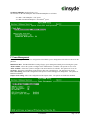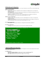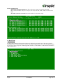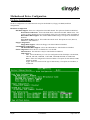
1
153 Cordaville Rd • Suite 310 • Southboro, MA 01772 • Phone: 508-983-0983 • Fax: 508-983-0984
XpressROMTM User’s Guide
Revision History
Revision
1.0
1.2
1.4
1.6
1.8
1.9
2.0
Insyde
Date
11/10/99
1/14/02
6/23/03
8/10/04
9/6/05
10/25/05
07/07/06
Comments
First Version
Second Revision
Third Revision
Fourth Revision
Fifth Revision
Post review
Update
-Confidential-
Page 1 of 15
Table of Contents
Overview......................................................................................................................................... 3
Quick Start ...................................................................................................................................... 3
Setup Menu Screens and Navigation .............................................................................................. 4
Main Menu ................................................................................................................................................................4
A. Changing the Time ...............................................................................................................................................4
B. Changing the Date.................................................................................................................................................4
C. Mother Board Device Configuration ....................................................................................................................5
D. Memory and Cache Optimizations .......................................................................................................................5
E. System Clock/PLL Configuration .........................................................................................................................6
F. Power Management ...............................................................................................................................................7
H. Miscellaneous Configuration ................................................................................................................................8
I. ISA I/O and Memory Configuration ......................................................................................................................8
O. Boot Order ............................................................................................................................................................9
Motherboard Device Configuration.............................................................................................. 10
C-A Drive Configuration.........................................................................................................................................10
C-C LPC Card devices ............................................................................................................................................11
C-D. DDMA Channel Configuration.......................................................................................................................11
C-F. Video and Flat Panel Configuration ................................................................................................................12
C-G GPIO Setting....................................................................................................................................................13
C-P PCI Configuration ............................................................................................................................................14
C-T Thermal Configuration.....................................................................................................................................15
Conclusion .................................................................................................................................... 15
Insyde
-Confidential-
Page 2 of 15
Overview
The following document is a user’s guide for Insyde’s XpressROMTM firmware for the AMD GeodeTM processors
including the AMD GeodeTM NX, LX, GX, SC1200, SC2200, SC3200, and GX1 processors. The user’s guide will
show you the menu systems for the firmware and a mechanism for flashing the BIOS on your platform. Insyde has
been working with AMD on the XpressROMTM firmware since 1999 and maintains a development relationship with
AMD. Insyde also supports the entire line of AMD products including AMD AlchemyTM, AMD AthlonTM, AMD
OpteronTM, AMD TurionTM, and AMD SempronTM processors.
The User’s Guide is applicable to all the AMD GeodeTM processor reference designs with the following part numbers
LX/CS5536 GX/CS5536 GX/CS5535
LX DB800
LX EPIC
LX ETX
Geode GX
GX DB533
SBC RDK
SP4GX22
Geode GX
Thin Client
SC1200/SC1201,
SC2200,SC3200
SC1100
GX1
SP4SC30
SP4SC40
SP2GX10
SP4SC31
DBSC1100
SP2SC20
DBSC1200
Quick Start
1) Download the latest Evaluation Copy of XpressROMTM
With a reference platform from AMD, the next step is to load the latest XpressROMTM for the platform. To find the
latest XpressROMTM for evaluation on the reference platform go to:
http://www.insydetech.com/productcenter/amd/geodesite/index.cfm
This website contains the latest released version of the XpressROMTM binary as well as a location to download boot
loaders for the reference platforms.
2) Flash latest version of XpressROMTM on AMD platform
Now that you have the latest evaluation copy of XpressROMTM, you must flash it onto your system by using either a
flash prom burner or using a flash utility supplied by Insyde Software.
If you do not have a copy of the flash utility, the website listed above contains a copy. Boot your system to DOS.
The command line to flash an xpress.rom image (256KB) of any size flash part (256/512/1024) is:
flashrom /D /sFFFC0000 xpress.rom
Where xpress.rom is the name of the binary you downloaded in step 1.
3) Clear CMOS
The next step is to boot your board and clear the CMOS. To clear the CMOS, boot the platform and enter the setup
by pressing F1 as the system is booting.
Select L. Load Defaults on the main menu
Next select X. Save Values and Exit.
4) Install OS and test system
The final step is to load the system with your operating system and test out the functionality.
Insyde
-Confidential-
Page 3 of 15
Setup Menu Screens and Navigation
The XpressROMTM Setup Menu contains a number of features and options. It is recommend that you evaluate the
menu options prior to shipment of your platform to ensure the removal of options that could have a negative
consequence if users change the items.
The controls for the setup menu are:
ESC
Back up menus or escape from a menu
Arrow Keys
Scroll up and down menus and change radio boxes
Arrow Keys
Scroll left and right in menus
<Enter> or <Return>
Select items in the menu or change status
Main Menu
The main menu is the first screen that appears from when a user selects F1 during the boot process. Below is a
screen shot of the main menu. Press the letter or use the arrow keys to select an option.
A. Changing the Time
To change the time select A from the main menu. You will be prompted with the following submenu
Enter the time in the format listed as an example: 11:30:01 then hit <enter>
B. Changing the Date
To change the date select B form the main menu. You will be prompted with the following submenu:
Insyde
-Confidential-
Page 4 of 15
Enter the date in the format listed as an example: 12/16/2005 then hit <enter>
C. Mother Board Device Configuration
The Mother Board Device configuration contains the only sub menu system of the setup screens. The choices are
Drive Configuration: Allows the configuration of the storage devices.
LPC Card devices: Allows for the configuration of the serial and parallel ports on an LPC Card.
DDMA Channel Configuration: Allows for the configuration of the ISA DMA channels.
Video and Flat Panel Configuration: Allows for the configuration of flat panels and video memory.
GPIO Setting: Allows for the configuration of GPIO pins.
PCI Configuration: Allows for the configuration of PCI Interrupt Steering and SMBus setting.
Thermal Configuration: Reads the LM82 temperature.
D. Memory and Cache Optimizations
The Memory and Cache Optimizations screen should not be left in a shipping system. Misconfiguring the memory
can render the system unable to boot. If the system is configured incorrectly, it may be necessary to short CMOS to
get the system to boot.
Cache Enable: Allows the configuration of the Cache of the system to be either Enabled or Disabled
Cache Mode: Allows the selection of the Cache mode to be either Write-Back or Write-Through
L2 Cache Enable: Allows L2 Cache of the system to be either Enabled or Disabled
Cache Allocate: Allows Cache Allocate to be either Enabled or Disabled
DIMM 0 or 1:
Memory Optimization DIMM 0 or 1: Allows the memory to be configured by Automatically or
Manually. If Auto is selected, DIMM Page Size, DIMM Size, Number of Devices, DIMM Module Banks,
and DIMM Component Banks will be grayed out.
DIMM 0 or 1 Page Size: Allows selections of Not Installed, 1, 2, 4, 8, 16 KB
DIMM 0 or 1 Size: Allows for the configuration of the Memory size to be 8M, 16M, 32M, 64M
128M, 256M, 512M
Number of Devices: Allows selections of 0, 2, 4, 8, 16, 32
DIMM 0 or 1 Module Banks: Allows for the configuration of the number of module banks.
Options are 1 or 2
DIMM 0 or 1 Component Banks: Allows for the configuration of the component banks Options
2 or 4
Insyde
-Confidential-
Page 5 of 15
CAS Latency: Allows the configuration Column Address Select latency. The options are Auto, 1.5CLK,
2CLK, 2.5CLK, 3CLK, and 3.5CLK
Refresh rate: Allows the setting of the memory refresh rate. Options include: Auto, 15us, 3us, 7us, 31us,
62us and 125us
Interleave selection: Allows the setting of the interleaving to either LOI (Low Order Interleaving) or HOI
(High Order Interleaving)
XOR BA0, BA1, or MB0: Allows the enable or disable of the XORing of module bank BA1or BA0 with
upper GLIU address bit. Options are Enabled and Disabled.
XOR Bit Select: Allows the XOR bit to be selected. Options are 18, 19, 20, and 21.
Memory Latencies: Allows the manual or auto configuration of the memory latencies
ACT2PRE: ACT to PRE Period (tRAS). Minimum number of clocks from the ACT to PRE
commands on the same component bank
PRE2ACT: Pre to ACT period (tRP). Minimum number of SDROM clocks between PRE and
ACT commands
ACT2CMD: Delay time from ACT to Read/Write (tRCD). Minimum number of SDRAM clocks
between ACT and Read/Write Commands
ACT2ACT: ACT(0) to ACT(1) Period (tRRD). Minimum number of SDRAM clocks between
ACT and ACT commands to two different component banks within the same module bank.
ACT2ACTREF: tRC = tRP + tRAS. May be set from 0 to 15.
REF2ACT: Refresh to Activity Delay (tRFC). Minimum number of SDCLKS 90-31) between
refresh and next command, usually an activate
E. System Clock/PLL Configuration
The system clock/PLL allows the setting of the clocks for the AMD GeodeTM system.
Clock Mode: Allows the clock speed to either be determined by the hardware strapping or manual settings. If the
H/W strapping option is selected, then the manual divisor settings will be grayed out.
Manual PLL Settings
CPU Multiplier: Options from 1 to 33
Insyde
-Confidential-
Page 6 of 15
GeodeLink Multiplier: Options from 1 to 33
The formulae for the CPU Multiplier and GeodeLink Multiplier are as follows
33.3 Mhz * CPU Multiplier = CPU speed
33.3 Mhz *GeodeLink Multiplier = GeodeLinkTM speed.
F. Power Management
The Power Management menu is for configuration of the BIOS’s power management with relation to the OS on the
platform.
BIOS PM at Boot: The BIOS PM allows setting of legacy power management mode prior to booting the system
APM Available: Allows the system to configure if the APM interface is available. The options are Yes or No.
ACPI Available: Allows the system to configure if the ACPI interface is available. The options are Yes or No.
S1 Clocks: Allows the configuration of the clocks to either run or not during S1. The options are On or Off.
CPU Clock Gating: Allows the configuration of the processor clocks during power management. The options are
Enabled or Disabled.
Chipset Clock Gating: Allows the configuration of the chipset clocks. The options are Enabled or Disabled.
Insyde
-Confidential-
Page 7 of 15
H. Miscellaneous Configuration
The Miscellaneous configuration screen focuses on a variety of functions, Use the (
) to select the function and
<enter> to change the value
Splash Screen Configuration
Splash Screen: Allows the configuration to have the splash screen displayed or not. The options are
Enabled or Disabled.
Clear Splash Screen: Allows the system to leave the splash screen on until the operating systems clears
the screen. The options are Enabled or Disabled.
Splash Screen Timeout: Sets the time for how long the splash screen is displayed. The time is in
milliseconds and goes from 0 to 65535. Enter the amount and select <enter>.
Summary Screen Configuration
Summary Screen: Allows the summary screen to be either displayed or not on boot. The options are
Enabled or Disabled.
Summary Screen Timeout: Sets the time for how long the summary screen is displayed. The time is in
milliseconds and goes from 0 to 65535. Enter the amount and select <enter>.
Power Button Configuration
Power button: Allows the power button to be configured with ACPI mode or Instant off
PC Speaker Configuration
AC Beeper: Allows the PC speaker to beep. The options are Enabled or Disabled.
I. ISA I/O and Memory Configuration
The ISA I/O and Memory Configuration screen allows the configuration of the I/O ranges mapped to ISA and the
memory ranges mapped to ISA.
I/O Mapped to ISA
I/O Range-0 though I/O Range-5: Allows the I/O range to be Enabled or Disabled.
Size: Selects the I/O range size. It may be set to 1, 2, 4, 8, 16, 32, 64, or 128.
Base Addr (A15-A8) / (A7-A0): Sets the base address for the I/O range.
Insyde
-Confidential-
Page 8 of 15
Memory Mapped to ISA
Mem Range-0 though Mem Range-3: Allows the memory range to be Enabled or Disabled.
Size: Selects the memory range size. It may be set to 16K, 32K, 64K, 128K, 256K, 512K, 1M, or 2M
Bytes.
Base Addr (A23-A16) / (A15-A8): Sets the base address for the memory range.
O. Boot Order
The Boot Order menu allows the alteration of the devices checked for a bootable image. There are six slots for
selecting the order. Use the arrow keys to select the order number and then press enter to cycle through the options.
The options are None, Floppy Disk, USB Floppy Disk, Hard Drive, CD-ROM Drive, USB Hard Drive/Flash Drive,
USB CD-ROM Drive.
Insyde
-Confidential-
Page 9 of 15
Motherboard Device Configuration
C-A Drive Configuration
The drive configuration screen determines the setup for the Hard drives, Floppy, CD-ROM, and Flash
configurations.
Hard Drive Configuration
IDE BIOS Support: Allows the configuration of the IDE channel. The options are Enabled or Disabled.
80-Conductor Cable Sense: Selects the GPIO that is connected to the IDE –PDIAG sense. The
options are None (Disabled), Force 40 Conductor Cable, Force 80 Conductor Cable, and GPIO 05.
DMA/UDMA BIOS Support: This enables DMA/UDMA timings. The options are Enabled and
Disabled.
Force mode for Drive 1 or 2: This enables the transfer mode. The options are Auto, PIO 0-4,
MDMA 0-2, and UDMA 0-5.
Floppy Configuration
Floppy BIOS Support: Allows the Floppy to be either Enabled or Disabled.
CD-ROM Boot Configuration
CD-ROM Boot BIOS Support: Allows the CD-ROM to be either Enabled or Disabled.
Flash Configuration: Allows the use of a flash device over the IDE.
Flash Interface: The flash device may be either Enabled or Disabled.
Chip Select 0- 3
Size: Allows the Memory size / I/O size configuration of the flash chips to be Disabled,
8K/16B, 16K/32B, 128K/64B, 512K/128B, 4M/256B, 8M/256B, or 256M/256B.
Base: Allows the configuration of the base address. The options are PCI default, D2000,
D4000, or D6000.
Type: Allows the selection of the type of flash memory. The options are Nor Mem, or
NAND I/O.
Insyde
-Confidential-
Page 10 of 15
C-C LPC Card devices
The LPC card configuration enables the configuration of each serial port and the parallel port on the LPC. To
change the serial port configuration use the arrow keys (
) to select the serial port and hit <enter> to change the
state. The choices are Disabled, 0x3F8 IRQ 4, 0x2F8 IRQ 3, 0x3E8 IRQ 4, 0x2E8 IRQ3
Serial Port 1-2: Allows the selection of the serial port address and IRQ. The choices are Disabled, 0x3f8 IRQ 4,
0x2f8 IRQ 3, 0x3e8 IRQ 4, and 0x2e8 IRQ 3.
Mode: Allows changing the serial port mode. The options are RS232 and RS485.
Parallel Port: Allows the selection of the parallel port address. The choices are Disabled, 0x378, 0x278, 0x3BC.
Mode: Allows changing the parallel port mode. The options are Compatible, PS/2 Bi-directional, EPP 1.7,
EPP 1.9, and ECP.
IRQ: Allows the configuration of the IRQ for the parallel port. The options are Disabled, IRQ5, IRQ7,
IRQ9, IRQ10, and IRQ11
DMA: Allows the configuration of the DMA for the parallel port. The options are None, Channel 3, and
Channel 1.
C-D. DDMA Channel Configuration
The DDMA Configuration screen allows the configuration of the DMA channels mapped to ISA.
DMA Channel 0-7 to ISA: Allows the DMA channel to be Enabled or Disabled.
Insyde
-Confidential-
Page 11 of 15
C-F. Video and Flat Panel Configuration
The following menu allows you to configure graphics settings for the system. To change an option, select the field
using the arrow keys and then select <enter> to change the value of the field. The menu system will also display the
bond out option for the parts, either flat panel or CRT.
Internal Adapter Mode: Allows you to select the mode for the internal controller when an external video device is
present. The options are Disabled, Primary Controller, and Secondary Controller.
Graphics Memory: Allows you to select the amount of video memory to reserve on the system. It may be set from
2 to 254 MB.
Driver controls init: Allows you to select whether the Operating System driver initializes the graphics or not. It
may be Enabled or Disabled.
Output display: Allows the selection of the display type. The choices include Auto, CRT, Flat Panel, TV output,
and Panel and CRT. Various menu selections are allowed or grayed out depending on this selection.
DOTPLL Bypass: Allows DOTREF pin to be used as the dot clock frequency. It may be Enabled or Disabled.
HSDIP Support: Allows the High Speed Data Input Port to be Enabled or Disabled. The HSDIP Memory Size
menu selection is grayed out when HSDIP Support is Disabled.
HSDIP Memory Size: Allows the memory size of the High Speed Data Input Port to be selected. It may be set
from 2 to 254 MB.
Flat Panel Configuration
Type: This enables the selection of the type of flat panel. The choices are Auto, TFT, and LVDS.
Typically, Auto is recommended. (If Auto is selected, then Resolution, Data Bus Type, Refresh Rate,
HSYNC Polarity, and VSYNC Polarity will be grayed out.)
Resolution: Allows the setting of the resolution of the panel. The choices are 320x240, 640x480,
800x600, 1024x768, 1152x864, 1280x1024, and 1600x1200.
Data Bus Type: Allows the selection of the data bus width and data type for the panel. The options are
9-24 bits, 1 ppc and 18,24 bits, 2 ppc.
Refresh Rate: Allows the selection of the refresh rate. The options are 60, 70, 72, 75, 85, 90, and 100
Hz
Insyde
-Confidential-
Page 12 of 15
HSYNC Polarity: Selects the active polarity of the HSYNC signal to the panel. The options are
Active Low or Active High.
VSYNC Polarity: Selects the active polarity of the VSYNC signal to the panel. The options are
Active Low or Active High.
LP Active Period: Selects the active period of the LDE/MOD (LP) signal. The options are Free
Running and Active Only.
SHFCLK Active Period: Selects the active period of the SHFCHK signal. The options are Free
Running and Active Only
Software Backlight Control
Backlight Enable: Selects if the software controlled flat panel backlighting is Enabled or Disabled.
Initial Brightness: Selects the initial backlight value for the panel. The options are Last Value, 0% (Off),
10%, 20%, 30%, 40%,50%, 60%, 70%, 80%, 90%, 100% (Full On)
TV Output Configuration This will be grayed out unless the Output display menu choice is set to TV output.
TV Encoder: This enables the TV encoder that is attached to the system to be specified. The choices
are AUTO, ADV7171, SAA7127, ADV7301, and FS454. (If Auto is selected, then TV Standard and
TV Resolution will be grayed out. TV Resolution may only be set for the FS454.)
TV Standard: Allows the TV display standard to be selected. The choices are NTSC, PAL, and
HDTV.
TV Resolution: Allows the setting of the television resolution. The choices are Low, Medium, and
High.
C-G GPIO Setting
The following menu system allows for configuration of some GPIO pins.
GPIO pins setting
GPIO6: This pin can be set to Available or used as the MFGPT0_RS pin.
GPIO25: This pin can be set to Available or used as the LOW_BAT# pin.
Insyde
-Confidential-
Page 13 of 15
C-P PCI Configuration
The following menu system allows the configuration of the PCI interrupts and SMBus setting.
PCI Interrupt Steering
PCI INT A# - INT D#: Use <enter> to cycle through the selections. The selections are Disabled, IRQ 1,
IRQ 3, IRQ 4, IRQ 5, IRQ 6, IRQ 7, IRQ 9, IRQ 10, IRQ 11, IRQ 12, IRQ 14, and IRQ 15.
SMBus Setting
SMBus: The PCI header of the SMBus may be Enabled or Disabled.
Insyde
-Confidential-
Page 14 of 15
C-T Thermal Configuration
The Thermal Configuration screen reads the current state of the CPU temperature from the LM82. The value is in
Celsius.
Conclusion
If there are any issues or questions on this product please contact:
Americas, Europe and Africa
Brian Gosselin
[email protected]
508-983-0983 x139
Asia Pacific
Daniel Lin
[email protected]
886-2-2506-1289 x511
Insyde Technology, Inc.
153 Cordaville Rd.
Southboro, MA 01772
Phone (508) 983-0983 • Fax (508) 983-0984
Insyde Software Corp.
Address: 6F, No. 137, Sec. 2, Chien Kuo N. Rd.
Taipei, Taiwan, R.O.C.
886-2-2506-1289
http://www.insydetech.com/
http://www.insydesw.com.tw/
Insyde
-Confidential-
Page 15 of 15