1
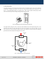
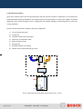
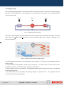
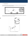
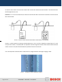
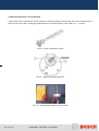
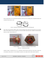
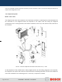
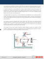
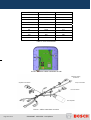
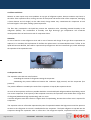
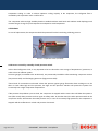
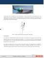
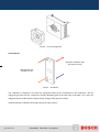
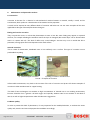
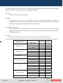
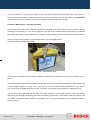
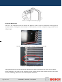
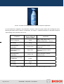
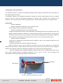
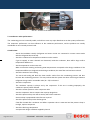
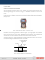
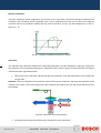
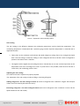
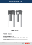
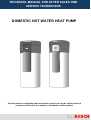
TECHNICAL MANUAL FOR AFTER SALES AND SERVICE TECHNICIANS DOMESTIC HOT WATER HEAT PUMP This document is confidential and restricted to exclusive use by the official technical assistance of Bosch in the countries of destination of this product. 1. INTRODUCTION ............................................................................................ 3 1.1 GENERAL DESCRIPTION ............................................................................................................ 4 1.2 PRODUCT PRESENTATION ......................................................................................................... 5 1.3 WORKING PRINCIPLE ................................................................................................................ 6 2. HEAT PUMP ELEMENTS .............................................................................. 7 2.1 ANODE PROTECTION ................................................................................................................ 8 2.2 ELECTRICAL RESISTANCE AND THERMOSTAT ........................................................................... 10 2.3 COIL FOR EXTERNAL SOURCE OF ENERGY ................................................................................ 12 3. MODULE ...................................................................................................... 12 3.1 COMPONENTS AND CHECKS IN THE REFRIGERATION UNIT ......................................................... 13 3.2 COMPONENTS SYSTEM ........................................................................................................... 14 3.3 MAIN COMPONENTS DATA ...................................................................................................... 17 3.4 ELECTRICAL MEASUREMENTS ................................................................................................. 19 4. COMPONENTS OVERVIEW ........................................................................ 23 4.1 COMPRESSOR ........................................................................................................................ 23 4.2 FILTERS AND DRIERS .............................................................................................................. 27 4.3 EXPANSION VALVE ................................................................................................................. 27 4.4 PRESSURE CONTROL BY NORMALLY CLOSED PRESSURE SWITCH ............................................... 28 4.5 EVAPORATOR ........................................................................................................................ 29 4.6 CONDENSER .......................................................................................................................... 30 5. HUMAN MACHINE INTERFACE – HMI ....................................................... 31 6. MAINTENANCE AND PREVENTIVE ACTIONS .......................................... 37 6.1 CORROSION........................................................................................................................... 37 6.2 WATER QUALITY .................................................................................................................... 37 6.3 TYPES OF SCALE .................................................................................................................... 39 6.4 MAINTENANCE ACTIVITIES FOR TECHNICIANS ............................................................................ 40 7. TROUBLESHOOTING .................................................................................. 47 7.1 FAILURES PREVENTION AND DETECTION ................................................................................... 50 7.2 EVAPORATOR UNDER PERFORMANCE ...................................................................................... 51 7.3 CONDENSER UNDER PERFORMANCE ........................................................................................ 52 7.4 OTHER RECOMMENDATIONS AND DEFINITIONS .......................................................................... 53 7.5 SERVICE NEEDS..................................................................................................................... 54 7.6 TERMINOLOGY ....................................................................................................................... 55 8. Page 2 from 63 APPENDIX.................................................................................................... 59 6720649497 SM HP270-1 2012/09 en 1. Introduction Domestic Hot Water Heat Pumps (DHW-HP), with or without air connections ducts, use the heat existing in the surrounding air, or the waste heat from the indoor air, as energy source for DHW preparation. These machines are commonly known as air-source hot water heat pump and they are energy-saving and environmentally friendly equipment with a plug-and-play system structure and easy maintenance. The heat pump has generally three operation modes: - normal mode – only heat pump operation; - combi mode– heat pump and electric resistance operation; - electric heater mode– only electric resistance operation; The heat source can be the waste heat as referred, but also the potential energy of unheated rooms, or the air discharged from rooms with high humidity such as bathrooms, toilets and laundry rooms. TTNR Brand Temp. Coil Commercial product name Product designation Market 7736500782 Bosch 7736500891 Bosch 7736500989 Bosch +5º/+35º +5º/+35º -10º/+35º Yes No Yes Compress 3000 DWFI Compress 3000 DWFI Compress 3000 DWFO HP 270-1E 1 FIV/S HP 270-1E 0 FIV/S HP 270-1E 1 FOV/S FR, GR FR FR, DK, GR 7736500991 Bosch -10º/+35º No Compress 3000 DWFO HP 270-1E 0 FOV/S 7736500781 Buderus +5º/+35º Yes Logatherm WPT 270 I-S HP 270-1E 1 FIV/S 7736500890 Buderus +5º/+35º No Logatherm WPT 270 I HP 270-1E 0 FIV/S 7736501013 Buderus -10º/+35º Yes Logatherm WPT 270 A-S HP 270-1E 1 FOV/S 7736501014 Buderus -10º/+35º No Logatherm WPT 270 A HP 270-1E 0 FOV/S 7736500884 elm leblanc +5º/+35º 7736500885 elm leblanc +5º/+35º 7736501015 elm leblanc -10º/+35º Yes No Yes Ondea PAC 270 AI-S Ondea PAC 270 AI Ondea PAC 270 AE-S HP 270-1E 1 FIV/S HP 270-1E 0 FIV/S HP 270-1E 1 FOV/S FR DE, BE, PL, CZ, AT DE, BE, PL, AT DE, BE, PL, CZ, IT, AT DE, BE, IT, PL, AT FR FR FR 7736501016 elm leblanc -10º/+35º No Ondea PAC 270 AE HP 270-1E 0 FOV/S 7736500169 Junkers +5º/+35º Yes SupraECO W SWI 270-1X HP 270-1E 1 FIV/S 7736500883 Junkers +5º/+35º No SupraECO W SWI 270-1 HP 270-1E 0 FIV/S 7736500988 Junkers -10º/+35º Yes SupraECO W SWO 270-1X HP 270-1E 1 FOV/S 7736500990 Junkers -10º/+35º No SupraECO W SWO 270-1 HP 270-1E 0 FOV/S 7736501149 Vulcano 7736501236 Vulcano +5º/+35º +5º/+35º Yes No AquaEco HP270-1 E S AquaEco HP270-1 E C HP 270-1E 1 FIV/S HP 270-1E 0 FIV/S Table 1: Appliances overview Page 3 from 63 6720649497 SM HP270-1 2012/09 en FR DE, BE, PL, CZ; ES, PT, AT DE, BE, PL, ES, PT, AT DE, BE, PL, IT, CZ, AT DE, BE, IT, PL, AT PT PT 1.1 General description This model of domestic hot water heat pump provides hot water for residential purposes, using a closed refrigerant unit filled with a refrigerant gas (R134a). This ensures the energy production taking out the energy from a cold source - air, and delivering this energy to a secondary circuit – water - where a simple circulation pump, ensures water movement through a heat exchanger, heating the water stored in a tank. (a) (b) Pict.1 (a) Refrigeration Unit and (b) Storage Tank (with coil) The engine absorbs energy “Qc” from a cold source (heat absorbed from air) and expels energy “Qh” to a hot destination (heat delivered to water) while Work “W” is done in the refrigerator circuit (electrical supply). The work done is ensured by an electrical plug that supplies electricity to the compressor and the movement of the refrigerant gas R134a ensures the transport of the energy from “Qc” to “Qh”. Heat sink (Qh) Condenser Flow direction Compressor (W) Expansion Valve Evaporator Heat source (Qc) Pict.2 – Heat Pump close circuit representation Page 4 from 63 6720649497 SM HP270-1 2012/09 en 1.2 Product presentation Apart of the main function of the heat pump operation with the required mandatory components of an air/water heat pump with electrical backup installed for any eventual need, the heat pump has, in some of the models, an internal integrated coil for external energy source as integration with existent standing or wall hung boiler or even solar energy installation. Picture 3 shows the internal constitution and main components: 1) Fan and evaporator group 2) Compressor 3) Condenser (Plate Heat Exchanger) 4) Filter dryer and expansion valve 5) Water circulation pump 6) Storage tank 7) Electrical resistance for backup 8) Internal coil for external backup (eg. solar) 1 2 4 3 5 6 7 8 Pict.3 – Main Elements of the Heat Pump (model +5ºC / +35ºC) Page 5 from 63 6720649497 SM HP270-1 2012/09 en 1.3 Working principle The heat pump working principle is based on the transfer of the heat, and not on conversion of electrical energy into heat. It removes energy from a low temperature source (ambient air) and transfers it into a high temperature source (hot water tank). Pict.4 – Energy and electrical input Electricity is used to upgrade the comfort (temperature) of heat energy and not to generate heat energy. That is the reason why COP (Coefficient Of Performance) of the heat pump is higher than 3 (which corresponds to an efficiency of 300 %). 2 1 3 4 Pict. 5 – Generic overview of the 4 stages of gas 1. Liquid refrigerant R 134a boils at a low temperature in the evaporator. The output is a low temperature and low pressure vapour. 2. Vapour pressure and temperature increase in the compressor. The electric motor is used to drive vapour through the compressor and increase vapour temperature and pressure. 3. Heat exchange is done in the condenser. The refrigerant transfers heat to the water and cools up, condensing and leaving energy there. 4. The liquid returns to the evaporator after passing through an expansion valve. decreases and the liquid evaporate again. Page 6 from 63 6720649497 SM HP270-1 2012/09 en The refrigerant pressure 2. Heat Pump Elements The top EPP cover must be carefully disassembled before any intervention on the module. Follow instructions from picture 6, existent in the sticker on the back of the tank. Pict.6 – Disassembling of top cover In front of the appliance and protected by an EPP front panel (fixed to the tank with 4 magnets), it is possible to find the magnesium anode and the electric resistance for backup. Pict.7 – Front view of the heat pump Page 7 from 63 6720649497 SM HP270-1 2012/09 en 2.1 Anode Protection The anode, installed in the water heater tank, will slowly dissipate whilst protecting it. The life of the water heater tank is ensured by the periodical inspection, done by an authorised person, replacing it when required. The anode inspection period shall take in consideration that, for softened water supply or in areas of worse water quality, it is recommended to inspect it more often and for some other critical different situations, a water treatment is recommended. The DIN 4753 determines that all magnesium anodes must be checked, at least each two years (considering normal conditions), ensuring a visual control. The acceptable water quality to the heat pump storage tank requires: - Water pH between 6,5 and 9,5 - Hardness range ≥ 3.0 ºdH. Depending on the appliance production date, the anodes can have a measured terminal, or not. Those which do not have a measurements terminal need a direct visual inspection to ensure its efficient operation and consequent life time of the tank. Anodes with measurement terminal must be connected to the HMI in order to ensure correct operation. (a) Anode without terminal (non isolated) (b) Anode with terminal (isolated) Pict.8 – Magnesium anode and measurement connections Pict.9 – Magnesium anode with measurement terminal Page 8 from 63 6720649497 SM HP270-1 2012/09 en An anodic current meter can be used to measure the current and evaluate the anode time life. The measured value shall be higher than 0,3 mA. Attention: For a correct measurement, the tank must be full with water! The electrical connection must be ensured after measurement. Pict.10 – Anodic current measurement with an anode tester or a multimeter Anyway, a visual inspection is strongly recommended every 2 year, in order to identify an eventual start of a crack in a part of the anode, or eventually the calc deposition over the magnesium anode surface which will decrease the anodic current as well, but will also disable the protection function of the anode. The visual inspection should include a material surface, weight, diameter and length changing control. Pict.11 – Example of used magnesium anodes Page 9 from 63 6720649497 SM HP270-1 2012/09 en 2.2 Electrical Resistance and Thermostat A thermostat control activates the electric resistance of 2kW immerged in the storage tank. This component has a safety function set at 90ºC, limiting the temperature from an external source (solar, boiler, etc, …) to 80ºC. Pict.12 – Electric Resistance (2 kW) Temperature adjustment Pict.13 – Bipolar thermostat interfaces Pict.14 – Check voltage supply o the thermostat Page 10 from 63 6720649497 SM HP270-1 2012/09 en Pict.15 – Check continuity between terminals After any intervention in the anode and/or thermostat, ensure the correct assembly with correspondent washer and assembly of the protection cover. Pict.16 – Protection cover of the thermostat and electrical backup group In the most recent production models, order to increase robustness of the tank in the models with coil, the electric heater of the models HP 270-1E 1 (with coil), is from was isolated. Spare part will is available as isolated electric heater for models, with and without coil. b b a a. Resistor (560Ω) a b. Dielectric insulation (tank / electric heater) Picture 17 – Isolated electric heater Attention: Resistor connection Picture 17.a is essential to ensure function and life time of the electric heater and, consequently, of the product. In case of defected component, the complete electric heater must be replaced. Page 11 from 63 6720649497 SM HP270-1 2012/09 en 2.3 Coil for external source of energy The coil integrated in the storage tank of some of the models (see table 1), can be used to combine the heat pump with a back up energy system like solar, boiler, etc. In case the coil will not be used, do not remove the caps from the coil inlet and outlet connections. This will avoid thermal losses due to the contact of the air in the coil with the surrounding hot water in the tank. In order to control the temperature in the tank for the external heat source, a pocket for external sensor is available and adapted to the available fixation systems of sensors in TT, ensuring the correct contact with the tank. Pict.18 – Storage tank and example of external sensor fixation system to pocket 3. Module A routine maintenance agreement should be taken with a licensed service person or organisation. In addition, endusers should monitor their installation and call a service person immediately, in case any abnormal operation/situation is found. The system should be serviced by a qualified person, every 12 months, depending on use/installation conditions. Junkers / ELM Leblanc Bosch / Buderus / Vulcano Pict.19 – Components overview Page 12 from 63 6720649497 SM HP270-1 2012/09 en Components checking procedure Unit o Inspect all the elements in the installation place o Check the airflow clearances o Check the output temperature o Clean the evaporator coils as following: – Clear the outside of the coil of debris – Vacuum the coil fins using a soft bristle brush attachment – take care to avoid bending the fins – Spray water from the inside to the outside of the coils to remove stuck debris using a hose and spray gun – Vacuum or remove by hand any remaining debris in the unit o Check if coil fins are damage – if bent, straighten them using a proper tool o Lubricate fan bearings if required – sealed bearing units do not require any oiling o Inspect fan and repair, if required o Ensure that the condenser unit is secure and levelled in both directions. If necessary, adjust the levelling feet on the appliance, or make level with timber/plastic shims. If the unit is seriously out of level, repair or replace the base of the unit. Refrigerant o Check the operation of the air-on/air-off with a digital thermometer o Check pipe joints for refrigerant leakage, with a bubble solution Electrical o Check terminals and connections – clean and tight if necessary o Check the voltage and current Service checklist o Provide the end-user with a filled service checklist after each service o Explain the importance of the thermal disinfection function (anti-legionella protection) for the water quality inside the tank 3.1 Components and Checks in the Refrigeration Unit The science of refrigeration is based on the fact that the liquid can be vaporized at any desired temperature by changing its pressure. Taking in consideration the example of water, that under a normal atmospheric pressure of 1,01 bar boils at 100ºC, if in a closed vessel under a higher pressure, it boils at a higher temperature. ATTENTION The technician for the refrigeration circuit must have specific material and tools to deal with these circuits and make the measurements and controls in the correct way, respecting the existing standards. Page 13 from 63 6720649497 SM HP270-1 2012/09 en The list of available material (separate document) must be checked in order to choose the adequate material for repairs in the refrigeration circuit. 3.2 Components System Model + 5ºC to +35ºC The refrigerant must enter in the evaporator, in the liquid state, and then, by vaporizing due to heat absorption from the surrounded air, the refrigerant leaves the evaporator in the vapour state and during the refrigerant condensation, there is a heat generation, which will be transferred, in this case, to the domestic water, that flows in the condenser. Pict.20 – General components overview in the module +5ºC / + 35ºC As the temperature of the available water is always higher than the one from boiling refrigerant in the evaporator, the refrigerant in the vapour state needs to be pressurized till its condensing temperature is above the temperature of the water available for the condensing process – that is why a compressor is needed. Page 14 from 63 6720649497 SM HP270-1 2012/09 en The compressor and condenser are needed to enable the same refrigerant to be used several times. The cost of compressing and condensing the vaporized refrigerant is far less than the cost of often renewing of the refrigerant. To maintain the difference in pressure between the condenser and the evaporator caused by the compressor, an expansion valve is needed. The expansion valve separates the high pressure from the low pressure side in the system. Only a small amount of refrigerant liquid flows through the valve. In fact, the valve is adjusted so that the liquid flow rate is the same as the evaporation rate. The refrigerant boils in the evaporator at a constant low pressure and temperature. Heat is removed from the air, cooling it. After leaving the evaporator, the vaporized refrigerant flows through the compressor, where the pressure of the vaporized refrigerant is raised to a point at which it can be condensed by some relatively warm fluid (water at normal conditions). The compressor removes the refrigerant vapour and this creates such a low pressure in the evaporator that the evaporation temperature is kept below the surrounding temperature. After being compressed, the vapour enters the condenser and is condensed at constant pressure and temperature. Heat is transferred from the condensing vapour through the walls of the condenser to the water in the tank. The expansion valve has two functions: maintain the pressure difference between the condenser and the evaporator, together with the compressor and regulate the volume of refrigerant going to the evaporator, in order to ensure a correct evaporation and allow the absorption of energy by the gas. Heat exchange (Air/R134) Expansion Compressor Heat exchange (R134/Air) Pict.21 – Schematic representation of heat pump principle Page 15 from 63 6720649497 SM HP270-1 2012/09 en Model - 10ºC to +35ºC The working principle of this model is the same as for +5ºC to +35ºC, with exception of the defrosting process, which is done through a solenoid valve, activated by the control unit, depending on the temperature measured by the NTCs, assembled in the evaporator fins and sensing the air temperature which will be detailed further in this manual. Pict.22 – General components overview in the module -10ºC / + 35ºC Page 16 from 63 6720649497 SM HP270-1 2012/09 en 3.3 Main Components Data Evaporator Suppliers: Behr, Mahle Specification from supplier: - Cooling capacity of 1.4 kW Specification from supplier: Fan - Supplier: EBM PASPT Centrifugal fan operation 230 V Specification from supplier: Compressor Suppliers: - 2 kW of heating capacity - Thermal protection included Mitsubishi (temperature limiter: opens at (model KB 134 VFN), 160ºC, closes at 70ºC) Highly (model WHP01900BSV) Condenser Specifications from supplier: - Supplier: Swep Maximum pressure 50 bar Specifications from supplier: Pump Supplier: Wilo ZRS12/2-3KV Page 17 from 63 6720649497 SM HP270-1 2012/09 en - 3 speed pump - maximum pressure 10 bar - IP44 - Q flow = 0.2 m3/h Specifications from supplier: - Liquid line filter drier Dry filter - Drying agent in bulk - Low pressure drop Supplier: Honeywell - Hermetic construction (Series FF) - Temperature range: TS = -40ºC / +80ºC MOP at +15ºC - TEV with built in orifice of 2 mm, bulb Ø of 12 mm, internal equalization Expansion valve and fixed superheating setting. Supplier: Honeywell Specifications from supplier: (Series TLK) - Thermostatic expansion valve for serial produced systems. Note: - Max. ambient temperature: 100ºC Capillary tube length of 1 m - Max. bulb temperature: 140ºC - Evaporating temp.: - 15...+40ºC - Inlet ODF: 3/8" / Outlet ODF: 1/2" Pressure Switch Low Pressure Switch (LPS) PS = 45 bar Supplier: Danfoss TS = 30ºC – 85ºC High Pressure Switch (HPS): PS = 45 bar TS = 30ºC – 85ºC Table 1 – Module components overview Page 18 from 63 6720649497 SM HP270-1 2012/09 en 3.4 Electrical Measurements Scheme A Scheme B Pict.23 – Electrical diagram -10ºC / +35ºC Position (Scheme Nr) Model Model +5ºC / +35ºC -10ºC / +35ºC A5 / B1 X A11 / B2 A13 / B3 Component Characteristics X Air NTC R 10k = 25ºC = 10000 Ω X X Hot Water NTC R 10k = 25ºC = 10000 Ω X X Cold Water NTC R 10k = 25ºC = 10000 Ω X Fins NTC R 8k = 25ºC = 8400 Ω A19 / B15 A12 / B10 X X Pump Wilo 230 (196 – 253) Vac 50 (47,5 – 52,5) Hz 19 / 32 / 48 W (0,10 / 0,15 / 0,21 A) A4 X X Condenser “Swep” type A14 X X Filter Drier PS = 11 – 43 bar Page 19 from 63 6720649497 SM HP270-1 2012/09 en Position (Scheme Nr) Model Model +5ºC / +35ºC -10ºC / +35ºC A15 X A2 X A20 / B16 A1 / B11 X Component Characteristics X Expansion valve TLK 2.0 R134a / MOP + 15ºC X Evaporator 14 x 3 tubes X Solenoid Valve 230 V / 50 Hz X Fan 230 (196 - 253) Vac 50 (47,5 - 52,7) Hz 85 W A3 / B7 X X Compressor 230 (198 - 264) Vac 50 (47,5 - 52,5) Hz 520-565 W / 475-490W (Mitsubishi / Highly) B6 X X Compressor Capacitor 17 μF / 15 μF (Mitsubishi / Highly) B8 X X Compressor Protection Bimetallic thermal switch (open at 160ºC, close at 70ºC) B4 X X Supply Cable to control unit 230 V (+10% / -15%), 50 Hz B5 X X High Pressure Switch Temp. = 60ºC Opening pressure = 27 bar* Closing pressure = 20 bar* B9 X X Low Pressure Switch Temp. = 5ºC Opening pressure = 0,7 bar* Closing pressure = 2,4 bar* A10 / B12 X X Electric resistance 230 V / 50 Hz (R=26,5Ω) A10 / B13 X X Safety Thermostat T sec = 90ºC B14 X X Control Unit 230 V (+10% / -15%), 50 Hz * Relative pressures Table 2 – Schemes A and B - components identification Page 20 from 63 6720649497 SM HP270-1 2012/09 en The NTC’s listed in the table above, are supplied in a common cable with the following configuration: (A) (B) (A) model -10ºC / +35ºC (B) model +5ºC / +35ºC Pict.24 – NTC cables The NTC sensors for air, cold and hot water are the same, but give different information to the software in the electronic control. Following table indicates the measurable resistance value to check and identify each proper function. These NTC sensors are a 10kΩ type. In case their minimum and maximum operation values are below or above the expected temperature/resistance values, the display will present the correspondent error code. The NTC sensor in the fins is 8kΩ with characteristic listed on table 3. NTC Resistance (Ω) NTC Resistance (Ω) (10kΩ type) (8kΩ) (fins) (air + cold + hot) -10 37450 55330 -5 29710 42320 0 23730 32650 5 19090 25390 10 15450 19900 15 12580 15710 20 10310 12490 25 8495 10000 30 7037 8057 35 5860 6531 40 4905 5327 45 4125 4369 50 3485 3603 Temperature (ºC) Page 21 from 63 6720649497 SM HP270-1 2012/09 en 55 2957 2986 60 2521 2488 65 2157 2083 70 1853 1752 75 1598 1481 80 1384 1258 85 1202 1072 90 1048 917 95 916 788 100 804 680 105 707 588 Table 3 – NTC characteristic Pict.25 – Electrical cables connection on HMI Electrical Supply connection Pump Connection Capacitor Connection Fan Connection Fan Capacitor Pict.26 – Cable connections overview Page 22 from 63 6720649497 SM HP270-1 2012/09 en 4. Components Overview 4.1 Compressor The compressor is usually driven by an engine and this unit compresses or transports the refrigerant through the system. The main principle is that the refrigerant is compressed as it is sucked into the compressor in a gaseous form at a low temperature from the evaporator. Pict.27 – Compressor It is then forwarded in gaseous form at a high temperature and high pressure to the condenser. The dimensioning of the compressor has to be adapted to the system size. The compressor is filled with special oil for lubrication purposes this is an important checking point for servicing. Lubrication Almost all refrigerant compressors contain oil, which lubricates the compressor moving parts and forms seals between these moving parts during the compression. The oil is important to achieve high efficiency in the compressor, but it affects negatively the heat transfer in the system. Compressors are lubricated (Oil content - 270ml) in order to: - reduce frictional wear on bearings and other moving parts - cool the refrigerant gas during compression - prevent refrigerant gas leakages The lubrication type depends on the compressor and the manufacturer recommendations must be followed. Page 23 from 63 6720649497 SM HP270-1 2012/09 en Electric test to the compressor: The compressor has some electrical connections and a temperature limiter thermostat that ensure its protection. Using a multimeter, is possible to control its functionality, nevertheless the HMI will detect if compressor is running. Cables and cover protection have clear identification of the different connections. C S R – Main electro valve S – Auxiliary electro valve R R C – Common Pict.28 – Compressor electrical connections and thermal protection Checking Continuity and Resistance (Ω) Between C – R > 0 Mitsubishi = 4.7 Ω / Highly = 5.84 Ω Between C – S > 0 Mitsubishi = 8.2 Ω / Highly = 7.62 Ω Between R – S > 0 Pict.29 – Testing compressor Page 24 from 63 6720649497 SM HP270-1 2012/09 en Electric test to compressor: Check earth connection C – chassis ≠ 0 S – chassis ≠ 0 R – chassis ≠ 0 Attention: In case of continuity the compressor is defected Pict.30 – Testing of compressor Thermal Protection This function is ensured by a bimetallic temperature limiter which opens its contact when high temperature (T=160ºC ±10ºC) is reached during operation. Pict.31 – Testing of thermal protection limiter Page 25 from 63 6720649497 SM HP270-1 2012/09 en (a) Open contact (b) Close contact temperature activation – T≥160ºC normal operation – T<70ºC Pict.32 – Functional position After any intervention, ensure correct cover protection assembly. Pict.33 – Cover of electrical elements from compressor Capacitor of Compressor Pict.34 – Discharging capacitor In case of check capacitor, discharge electric charge with a resistance of 20k and 2W Not OK - ∞ OK - 0Ω Pict.35 – Capacitor testing Page 26 from 63 6720649497 SM HP270-1 2012/09 en 4.2 Filters and driers Moisture or water vapour may cause problems in any type of refrigerant system, because moisture may freeze in the orifice of the expansion valve, causing corrosion of metal parts and wet the motor of the compressor, damaging it (motor burnout and oil sludge). On the other hand, foreign matter may contaminate the compressor oil and become lodged in valve parts, making system inoperative. The filter drier, positioned in the liquid line protects the expansion valve, absorbing potential humidity in the refrigerant (R134a). The combination of humidity and high discharge gas temperatures will accelerate decomposition of the oil and increase risk of compressor failure. Attention: In case of need to access refrigerant circuit and in case of remove and charge of new gas when components are replaced, it is mandatory the replacement of the filter the replacement is recommended because if a filter in the liquid line becomes blocked, there will be a pressure drop refrigerant to boil and create flash gas, which will disrupt the operation of the expansion valve. Pict.36 – Filter Drier (cut model for internal view) 4.3 Expansion valve The expansion valve has two main functions: - Controlling the amount of refrigerant entering the evaporator: - Maintaining the pressure difference between the condenser (high pressure) and the evaporator (low pressure): The pressure difference created by the work of the compressor is kept by the expansion device. As much of the evaporator surface as possible should be covered with liquid refrigerant without liquid being carried over to the compressor. If the capacity of the evaporator increases, the expansion valve should allow a larger flow of refrigerant (bulb detects high superheating) and vice versa. A smaller refrigerant mass flow results in a higher level of superheating, because less surface area is required for evaporation The expansion valve or orifice tube represents the point of separation between the high pressure and low pressure sections in the refrigerant circuit and is installed before the evaporator. The liquid refrigerant is injected into the evaporator through the expansion valve or orifice tube. The refrigerant expands, evaporates and thus releases Page 27 from 63 6720649497 SM HP270-1 2012/09 en evaporation cooling. In order to achieve optimum cooling capacity in the evaporator, the refrigerant flow is controlled by the expansion valve or orifice tube. The component achieves high durability thanks to welded stainless steel head and stainless steel diaphragm and contains the gas charge for quick response time adapted to small evaporators. ATTENTION: In case of replacement, the component should be protected from the heat during soldering process. Pict.37 – Expansion valve (cut view) 4.4 Pressure control by normally closed pressure switch In this closed refrigerant circuit, is very important to be sure about the correct range of temperatures / pressures, in order to have an efficient system. Pressure gauges (accessible to the technicians), are permanently installed to allow monitoring compressor suction (low pressure side) and discharging pressures (high pressure side). These kinds of connections use throttle valves that prevent against gauge fluctuation when readings are to be taken. In both sides high and low pressure, the high and low pressure switches will protect the system from excessively low or high compressor temperatures. If the pressure drops below a pre-set level, the compressor is stopped and the same valve will allow the system to start (after reset) when pressure reaches again its safety value. In the other hand, the other pressure switch in the compressor outlet, will measure the outlet pressure and, in case of excessively high pressures, the compressor is stopped until the malfunction is solved and pressure decreased. Page 28 from 63 6720649497 SM HP270-1 2012/09 en Pict.38 – Pressure switch from Danfoss Various shunt relays are triggered by the pressure switch in order to guarantee safe and effective use of the refrigerant system under all conditions. Through this process, individual system components are switched on and off according to the defined pressure points. The pressure switches can fail due to contacting problems or soiling. Regular system servicing prevents failure. Pict.39 – Pressure switch, filter drier and expansion valve group 4.5 Evaporator The evaporator is used for the heat transfer between the air surrounding and the refrigerant in the system. The refrigerant entering the evaporator under pressure expands, i.e. it converts from a liquid to a gaseous state, and thus "evaporates" in the evaporator. The cooled air produced by this process is discharged to the environment via the large surface of the evaporator. Up to 50% less weight and up to 40% less volume for the same capacity - the striking features of Behr's disc evaporators have advantages in comparison with traditional round-pipe evaporators: quicker draining of condensation, lower air resistance, higher air flow and reduction of micro-organisms that cause annoying smell. Page 29 from 63 6720649497 SM HP270-1 2012/09 en Pict.40 – Fan and Evaporator 4.6 Condenser Domestic Hot Water Side (Secondary circuit) Refrigeration side (Primary circuit) Pict.41 – Condenser The condenser is required to cool down the refrigerant heated up by compression in the compressor. The hot refrigerant gas flows into the compressor, thereby dissipating heat to the other side of the plate. As it cools, the refrigerant pressure falls and the refrigerant state changes from gaseous to liquid. Soldered flat pipe condensers have high capacity and less volume. Page 30 from 63 6720649497 SM HP270-1 2012/09 en Pict.42 – Plate heat exchanger condenser working principle In case of hard water, the condenser shall be periodically cleaned in order to avoid obstruction. Pict.43 – Plates of the heat exchanger and counter-flow representation 5. Human Machine Interface – HMI User manual must be used to verify functions and active parameters. For the service mode, following instructions should be considered. The control unit has a standby consumption of 3W. Page 31 from 63 6720649497 SM HP270-1 2012/09 en Display (LCD) Selection Buttons Pict.44 – HMI Panel Entrance in the service mode: Press “Menu” + “Ok” button during more than 5 sec Pict.45 – Enter in service mode Table 4 includes the meaning of each parameter visible on the service mode that can be used by technicians for diagnostic and repair actions. +5 / +35 -10 / +35 Parameter X X 0d X X 1d X X 2d Description Set point temperature of hot water on control unit Temperature of Hot Water (NTC in the top of the tank) Temperature of cold water (NTC between pump and condenser) Active Symbol Unit ºC ºC ºC Temperature of air in circulation X X 3d (NTC between air admission and ºC evaporator) X 4d Temperature of the evaporator (NTC in the fins) ºC Current Consumption X X 5d (Instantaneous electrical consumption of compressor) Page 32 from 63 6720649497 SM HP270-1 2012/09 en A X X 6d Number of air defrost procedures + X 7d Number of gas defrost procedures + last 10 failures with error code indication X X 1F until 10F Attention: + (If no error is memorized, display shows “-- --“) X X EE X X AL X X E cleaning of the historical memory of the last 10 failures test display (all segments ON) Exit Service Mode (for FD<202, minimum press time of 3sec) Table 4 – Service Mode Parameters Working modes: Error Mode OFF Mode Reset function by pressing OK button for more than 3 sec Anti-Freeze Protection function active for tank and module Stand-by Mode Operation Mode Diagnostic / Adjustment Mode * - Combi Mode* HP Mode Electrical Mode Full - Adjustment Mode Service Mode In case the air temperature is out of the specified range, the appliance automatically activates the electrical back up (without leaving the Combi mode). One hour after the warning display (HOT or COLD) has appeared, the appliance checks the air temperature again and, if it is within the range values, turns again to heat pump operation. The control loop is done every hour, after electrical back up emergency operation. Page 33 from 63 6720649497 SM HP270-1 2012/09 en The working principle is based in the following considerations: Switch OFF No Reaction from system Switch ON (main switch in the back of HP) Error in memory? no yes Stand-by mode (1) 1) Error Mode For Stand-by Mode (1) Stand-by mode HMI actuation LCD Backlight ON LCD Backlight OFF (after 15 sec without any selection) Active Operation Mode Temperature of the Tank Clock & Day Function Temperature Selection Page 34 from 63 Temperature Blinks until confirmation with OK button 6720649497 SM HP270-1 2012/09 en Temperature remain previous one after 10 sec without any selection Conditions for operation: The heat pump compressor is activated according the following conditions and according control unit settings defined. TTop ≤ T set – 3ºC (and Tbottom < 60ºC) Start Up TTop ≥ T set (or Tbottom ≥ 62ºC) Stop Conditions for anti-freeze protection (in HP or Standby mode): Software version after HPAF0211 (-10ºC models) and HPAF0311 (+5ºC models): TBottom < 4ºC Module Anti-Freeze: Water pump runs for 2 minute Tank Anti-Freeze: Water Pump ON + Electrical heater ON till TTop>8ºC TTop ≤ 5ºC Software version before versions HPAF0211 (-10ºC models) and HPAF0311 (+5ºC models): TBottom < 2ºC Module Anti-Freeze: Water pump runs for 1 minute TTop ≤ 20ºC and TBottom < 5ºC Tank Anti-Freeze: Water Pump ON + Electrical heater ON till TTop>25ºC or TBottom > 10ºC Conditions for legionela disinfection: Water pump is always ON (for both “Man” or “Aut” selection) Page 35 from 63 6720649497 SM HP270-1 2012/09 en Full mode until Ttop = 60ºC Electric Heater mode until Ttop = 70ºC Legionela stops when: TTop≥70ºC or TBottom ≥ 60ºC (or time in Legi > 24h) Conditions for air-defrost sequence: Air defrost sequence is activated in both +5ºC or -10ºC models when T air > 5ºC and < 10ºC for more than 60 min: Tbottom < 20ºC (defrost every 90 min) Tbottom < 35ºC (defrost every 150 min) Tbottom < 60ºC (defrost every 240 min) Compressor OFF Fan ON during 10 min Water Pump OFF Conditions for gas-defrost sequence: Gas Defrost sequence is activated only in -10ºC models when T air > -10ºC and < 5ºC for more than 15 min, performed in 2 steps (Pre-gas defrost + Gas defrost), when Compressor ON for more than 180 min or Compressor ON for more than 60 min and Tair-Tfins > 3.5ºC for more than 1 min. st nd 1 step: Pre-Gas Defrost Compressor ON 2 step: Gas Defrost Solenoid OFF Fan ON Compressor ON Fan OFF Time for pre-gas defrost: Tbottom < 25ºC / Time = 2 min Tbottom > 25ºC and < 40ºC / Time = 1 min Tbottom > 40ºC / Time = 0.5 min Page 36 from 63 Solenoid ON 6720649497 SM HP270-1 2012/09 en Gas Defrost sequence stops when Tfins > 6ºC (for more than 30 min) 6. Maintenance and preventive actions 6.1 Corrosion Corrosion is the term for a chemical or electrochemical reaction between a material, usually a metal, and its environment, which produces a deterioration of the material and its properties. A metal can be exposed to many different kinds of corrosion and below we can see some examples of the ones applicable to this type of brazed plate heat exchangers. Pitting and crevice corrosion They are quite the same, or at least the phenomenon is more or less the same. Pitting may appear on exposed surfaces, for example attacking the stainless steel if the layer is damaged (this natural layer can be formed when steel is in contact with air). This kind of defect may cause leakages. Crevices may occur in welds that fail to penetrate, in flange joints and under deposits on the steel surface. General corrosion This is a kind of deterioration, distributed more or less uniformly over a surface. This type of corrosion is more predictable than pitting. a) General copper corrosion b) Pitting corrosion in stainless steel Pict.46 – Examples of corrosion Unfavourable environment, may lead to the increase of the risk of corrosion and picture 45 shows examples of corrosion in either stainless steel or copper brazing. This kind of heat exchangers are sensitive to high concentrations of chloride ions in an oxidizing environment, because chlorides form a galvanic cell with oxygen and specially stainless steel is too sensitive to this kind of attack, as well as higher temperatures make chlorides more aggressive. 6.2 Water quality In order to prevent this kind of phenomena, it’s very important for the installer/technician, to evaluate the water quality and, warn the end user and prepare the installation accordingly. Page 37 from 63 6720649497 SM HP270-1 2012/09 en The corrosive effect of natural water can vary considerably with its chemical composition. Water quality is of great importance to avoid corrosion in the plate heat exchanger (condenser). City Water Normally is controlled and of good quality. Well water Is usually fairly cold and clean, which implies that it has a low biological content. However, the concentration of scale forming salts (calcium and magnesium sulphates and carbonates) can sometimes be very high. Pitting corrosion may be initiated due to salt deposits. River and lake surface water The concentration of scale forming salts is usually fairly low. However, there may be amounts of solids ranging from salts and soil particles to leave. Some type of pre-treatment is necessary, particularly to control biological activity Sea water Is not recommended because of the corrosive action of very high chloride concentrations Check water quality and recommendation of use of the supplier of the condenser (SWEP), represented in table 5. Concentration Water Content Alkalinity (HCO3-) Sulphate (SO4 2- ) HCO3- / SO4 2 - Electrical Conductivity pH Ammonia (NH3) - Chlorides (Cl ) Page 38 from 63 AISI 316 COPPER <70 + 0 70 – 300 + + >300 + 0/+ <70 + + 70 – 300 + 0/+ >300 0 - >1 + + <1 + 0/+ < 10 μS/cm + 0 10 – 500 μS/cm + + > 500 μS/cm + 0 < 6.0 0 0 6.0 – 7.5 0/+ 0 7.5 – 9.0 + + > 9.0 + 0 <2 + + 2 – 20 + 0 > 20 + - < 300 + + (mg/l or ppm) 6720649497 SM HP270-1 2012/09 en Free chlorine (Cl2) Hydrogen Sulfide (H2S) Free (aggressive) carbon dioxide (CO2) Total Hardness (ºdH) Nitrate (NO3) Iron (Fe) Aluminium (Al) Manganese (Mn) > 300 0 0/+ <1 + + 1–5 + 0 >5 0/+ 0/- < 0.05 + + > 0.05 + 0/- <5 + + 5 – 20 + 0 > 20 + - 4.0 – 8.5 + + < 100 + + > 100 + 0 < 0.2 + + > 0.2 + 0 < 0.2 + + > 0.2 + 0 < 0.1 + + > 0.1 + 0 Symbols explanation: + Good resistance under normal conditions 0 Corrosion problems possible, particularly when there are other factors rated 0 - Use is not recommended Table 5 – Water composition parameters Table 5, gives an idea of the resistance of AISI 316 stainless steel and pure copper (99,9%) in water to corrosion by some important chemical factors. However corrosion is a very complex process influenced by many different factors in combination, this table is a considerable simplification, which should be taken in consideration. 6.3 Types of scale Calcium carbonate (CaCO3) can be formed when calcium or bicarbonate alkalinity is present. An increase in heat and / or an increase in pH will cause precipitation of calcium carbonate. Calcium Sulfate (CaSO4) is 50 times more soluble than calcium carbonate and will, therefore, precipitate only after calcium carbonate is formed. This type of scale can exist in various forms, and its formation depends strongly on the temperature. An increase in temperature decreases the solubility of this salt and increases the risk of scaling. Water scaling tendency In order to estimate the scaling tendency of natural water, several parameters must be analysed and determined: Page 39 from 63 6720649497 SM HP270-1 2012/09 en o pH o calcium content o alkalinity o ionic strength of the water (Is) Please note: - For water analysis, mg/l is equivalent to ppm - The relation between calcium and calcium carbonate is 40g CA 2+ ≃ 100g CaCO3 - TDS = salt content (mg/l) or possibly the conductivity x 0.63 (μS/cm) If Is<0, the water has a tendency to be corrosive. If Is>0, the water has a tendency to cause scaling. Eliminating the scaling problems There are several ways to eliminate the scaling problem. Usually a commercial product containing additives to enhance the effect and / or prevent corrosion can be used; nevertheless a specialist should be consulted to recommend the adequate procedure for the treatment. Chemical cleaning is the use of chemicals to dissolve or loosen deposits from process equipment and piping. Removal is uniform and generally at a low cost. Step 1: Chemical cleaning solutions Using organic acids (are weaker than mineral acids but safer to material and handling). The organic acids can be used in combination with other chemicals to remove the scale completely. Acetic acid is used to clean calcium carbonate scale. Step 2: Passivation Passivation is a procedure to remove surface iron contamination from the equipments. 6.4 Maintenance activities for technicians In terms of maintenance, it is strongly recommended a general control of the main components of the heat pump, before the control of the refrigerant module circuit. Component Image Action Electric measurement1) or visual inspection Magnesium anode 1) Page 40 from 63 6720649497 SM HP270-1 2012/09 en Depending on the version Check position*, connection, continuity Cables * Ensure distance to copper pipes Manual activation Safety valve Pre-charge verification (vessel without Expansion vessel water pressure) Leakages, lack or defective insulation Pipe work Cleaning of calc deposition, inspection of Heating element integrity Table 6 – Resume of main maintenance actions The main connections are through thread connection with washer, however and for the connections of the flexible hose with o’ring connection, the lubricant L 641 (part nr 8 709 918 413 - Water lubricant for water valve connections) must be used. (a) (b) Pict.47 – (a) O’ring lubricant in water connections (b) white conductivity thermal paste Page 41 from 63 6720649497 SM HP270-1 2012/09 en In the NTC sensor, in contact with the pipe of cold water from the bottom of the storage tank, and in the NTC sensor, in the pocket of the hot water from the top of the tank, the thermal paste “Wacker” (part nr 8 719 918 658) must be used to ensure an efficient contact and consequent efficient temperature sensing. Condenser Maintenance - Descaling procedure The process of descaling in the condenser of plate heat exchanger type can be done in the place, with no need of removing the component. In cases where water flow from tank to the condenser plate heat exchanger is blocked with debris, lime scale or other substances, it is strongly recommended the use of a pump, by the technical service. Picture 47 shows one example of a recommended pump, from the supplier Sanit. (Available models: KalkMax 500 or 800) Pict.48 – Sanit Kalkmax pump According to the supplier of the condenser (SWEP), with this type of components it can be used a liquid such as Kaloxi. This cleaning compound especially developed to dissolve and remove the internal deposition of scale forming salts in water supplied systems is caustic, with a pH-value of 1,5 and it consists of 9% of Phosphorous acid, 35% of citric acid and 1% of inhibitor with 55% of water. The waste of this cleaning liquid should be neutralized to PH7. These acids are bio-degradable and non-toxic and remove all types of scale as well rust that can be accumulated inside of heat exchangers obstructing water flow and reducing heat transfer. The inhibitor makes this product work as a buffer and protects all the sensitive components you find in heat exchangers and in complete heating or cooling systems. Page 42 from 63 6720649497 SM HP270-1 2012/09 en Pict.49 – Kaloxi descaling liquid to clean plate heat exchangers Descaling process: - Close cold water inlet and open hot water tap to take out pressure from the top of the heat pump; - Remove connection in the top of the condenser plate heat exchanger to allow the outlet of the water and then, remove the connection in the bottom; Pict.50 – Unscrew water connections to the condenser plate heat exchanger - Page 43 from 63 Connect flexible connection of the pump already with the liquid 6720649497 SM HP270-1 2012/09 en Pict.51 – Flexible hose of descaling pump connection - Put the pump in operation, taking in consideration that the flow must be, inside the heat exchanger, in the opposite direction of the water. The direction can be defined in the pump on the correspondent lever, as shown in picture 51. Pict.52 – Flexible hose of descaling - Leave the pump in operation for some minutes to remove lime scale. - After cleaning process, make circulation with clean water to eliminate vestiges of the acid solution In the models with manual air purge (depending on production date), ensure its correct purging position. Page 44 from 63 6720649497 SM HP270-1 2012/09 en Pict.53 – Example of a manual air purge Evaporator Maintenance The fins of the evaporator should be cleaned and aligned in order to allow an adequate air flow through the complete surface, ensuring the correct function of the evaporator, and the consequent energy transfer to the refrigerant gas. Pict.54– Detail of the fins and 3 passages evaporator (cut model) Pict.55 – Damaged fins in the evaporator The alignment of the fins can be done with an adequate brush and the cleaning process, with a vacuum cleaner. During maintenance, the surface of the evaporator can be sprayed with the same available solution in the market as for air conditioning, which cleans and avoids deposition of dirtiness. Page 45 from 63 6720649497 SM HP270-1 2012/09 en Pict.56 – Example of cleaning and purifier spray for evaporators application For the maintenance, diagnostic and performance analysis of the heat pump module and its refrigerant circuit, following information must be taken in consideration. On chapter 7, additional information is described to help the understanding of the operation of the circuit. Parameter Value for (+5ºC to +35ºC) and (-10ºC to +35ºC) Type of refrigerant R134a Gas charge 375 g Comments GWP = 1300 / ODP = 0,00 Ebullition temperature = - 26,1 ºC 3,5 bar / 10ºC outlet of evaporator / inlet to compressor Discharge pressure / Temperature 8 bar / 50ºC outlet of compressor / inlet to condenser Internal pressure / Temperature 3,5 bar / 4ºC Inlet of evaporator / outlet of expansion valve Suction pressure / Temperature Refrigerant pressure drop on evaporator 0,3 bar Super heat 3,8 K Sub cooling 2K Table 7 - Design data of the heat pump for inlet water and inlet air at 15ºC Page 46 from 63 6720649497 SM HP270-1 2012/09 en 7. Troubleshooting Code E01 Lock Out error Fault in the hot water NTC temperature sensor (in the top of the tank) 1 Sensor is disconnected Check connection to control unit and cable integrity 2 Sensor is in short circuit Check cable, sensor and measure NTC value 3 NTC has values out of its borders Measure NTC sensor value Code E02 Lock Out Error Fault in the cold water NTC temperature sensor (blue mark) 1 Sensor is disconnected Check connection to control unit 2 Sensor is in short circuit Check cable, sensor and measure NTC value 3 NTC has values out of its borders Measure NTC sensor value Code E03 Lock Out Error Fault in the air NTC temperature sensor (yellow mark) 1 Sensor is disconnected Check connection to control unit and cable integrity 2 Sensor is in short circuit Check cable, sensor and measure NTC value 3 NTC has values out of its borders Measure NTC sensor value Code E04 Warning Code (self reset error) Temperature in storage tank higher than 80ºC (Detected by the hot water NTC in the top of the tank) 1 Heat Pump storage tank connected to a solar installation. Reduce maximum temperature of storage tank in the solar controller 2 Heat Pump storage tank connected to a boiler installation Reduce the sanitary water set point in the boiler 3 Hot Water NTC sensing wrong temperature value Measure NTC sensor value (multimeter in Ω position) Code E05 – ONLY in model -10ºC - Lock Out Error Fault in the Fins Evaporator NTC temperature sensor (white cables) 1 Sensor is disconnected Check connection to control unit and cable integrity 2 Sensor is in short circuit Check cable, sensor and measure NTC value 3 NTC has values out of expected range Measure NTC sensor value Code E06 Warning Code Setting buttons hold down for longer than 30 seconds. Page 47 from 63 Self Reset after release buttons 6720649497 SM HP270-1 2012/09 en Code E07 – Only for internal technical use Code E08 – Only for internal technical use ONLY FOR models, produced till February 2012 Code E09 Lock Out Error Failure in Compressor System Condition: Appliance was turned on, is in standby and fault was displayed before operation 1 Contacts Open on safety elements - thermal protection Check Continuity 2 Contacts Open on safety elements – high pressure switch Check Continuity 3 Contacts Open on safety elements – low pressure switch Check Continuity High Pressure Switch Activation Condition: After first start up of system, fault is displayed after HP start operation 4 Water pump operation is noisy 5 Circulation pump is not working Check air presence in the sanitary side / pump and purge it Check pump connection and its operation Unblock the pump impeller through the front screw. Condition: Appliance blocks after some running time 6 Water flow through condenser is too low 7 Water shortage >12h 8 After a repair and / or R134 replacement Check eventual calc or debris deposition in the sanitary side of the condenser plate heat exchanger and clean it. Too much refrigerant inside circuit (max. 375 g). Rework charging procedure. Code E10 Lock Out Error Fault in the electrical backup resistance (by current sensor in control unit) 1 Activation of the safety thermostat (over temperature) 2 In case of repetitive error, drain water and disassemble resistance. Reset thermostat manually (check adjusted temperature – must be at maximum position “+” aprox. 80ºC) In case of appliance with internal coil, check water temperature from the backup system (solar, boiler, …) – must be < 80ºC Calc deposition over resistance surface avoids thermal dissipation and consequent over temperature detection. Resistance malfunction. ONLY FOR models produced from March 2012 on Code E11 Lock Out Error Failure in Compressor System Condition: Appliance was turned on, is in standby and fault was displayed before operation 1 Page 48 from 63 Contacts Open on safety elements - thermal protection 6720649497 SM HP270-1 2012/09 en Check Continuity 2 Contacts Open on safety elements – high pressure switch Check Continuity 3 Contacts Open on safety elements – low pressure switch Check Continuity Fault in the low pressure side 1 High pressure loss in the air ducts Check ducts and accessories equivalent length 2 Failure in fan operation Check fan operation and connection 3 Leakage in the refrigeration circuit Check with an leakage detector the origin of the leakage, repair and refill circuit. 4 Over current limiter activation Check compressor - blocked 5 Expansion valve does not leave correct amount of gas for evaporator Check bulb position and insulation 6 Expansion valve is blocked or bulb has lost charge Repair by replacing the complete expansion valve 7 Dry filter is saturated and block refrigerant flow (filter outlet is much colder than inlet) Replace filter Code HOT Warning Code Temperature of air admission higher than + 35ºC. 1 Self Reset error after normal temperature conditions are reached Code COLD Warning Code Temperature of air admission lower than + 5ºC or - 10ºC according model. 1 Self Reset error after normal temperature conditions are reached Table 8 – Error codes identification ATTENTION: The technician for the repairs in the refrigeration unit of the heat pump, must have competences in soldering, repairing and analysis of performance of the machine, to ensure safety and correct servicing of the unit. Only a certified technician, with adequate training from the respective entities in the country of destination, can give the certificate of competence to the authorized persons to carry out service and maintenance in heat pump machines. Page 49 from 63 6720649497 SM HP270-1 2012/09 en 7.1 Failures prevention and detection The design data supplied by Bosch must be known by authorized service partner’s technicians, in order to prevent and avoid the following problems, nevertheless, the service partner is responsible to prepare technicians in such a way that the following problems will never happen in the field with an end user. - Refrigerant leaks after repairs and / or components replacement; - Defective soldering or damaged components due to lack of knowledge in this area; - Maintenance operations without recovery of refrigerant gas and correspondent treatment according country laws and directives; The vacuum of the system can be done using the two available charging probes, and must be performed correctly in order to guarantee no moisture inside of refrigeration system. The filter dryer must be replaced every time that the refrigeration system is opened and serviced, in order to avoid reading the saturation point. The bulb position must be ensured, in the top position after the evaporator, to allow a correct reading and a proper functionality of the expansion valve. In case of HMI replacement, respect and assemble the NTCs in the correct position to avoid wrong temperature detection. For the analysis of common failures (even without error code), the following material is recommend in order to ensure a better detection of the origin of the malfunction by the refrigerant circuit technician. Pict.57 – Tools for working pressure measurement in both high and low pressure side Table 9 indicates the design data of the heat pump, in order to allow the refrigerant technician to repair, make vacuum and re-charge the R134a in the unit in case of malfunction detection in the refrigeration circuit. Temperature (ºC) -30 -25 -20 -15 -10 -5 0 5 10 Pressure (Bar) 0.84 1.06 1.33 1.64 2.01 2.43 2.93 3.5 4.15 Temperature (ºC) 15 20 25 30 35 40 45 50 Table 9 – Working pressures and temperatures Page 50 from 63 6720649497 SM HP270-1 2012/09 en Pressure (Bar) 4.88 5.72 6.65 7.7 8.87 10.17 11.6 13.18 7.2 Evaporator under performance The evaporation process is sensitive and potentially unstable. Minor changes in performance have major effect on the system performance (COP). A one-degree change in the evaporation temperature changes the COP by approximately 3% and an unstable process could also cause the evaporation temperature to fluctuate, with a potential risk of freezing in the evaporator. The critical parameter for the system performance is the saturated pressure at the compressor inlet. Check Points: - Check the installation - Check the evaporation temperature at the compressor inlet Use compressor data to compare with cooling data - Check the evaporation pressure at the evaporator outlet Compare the evaporation pressure at the outlet with the evaporating pressure at the compressor inlet. This difference should be kept to a minimum to avoid unnecessary losses in cooling capacity. This should be measured in the suction side of the compressor (pressure gauge available). By measuring the temperature in the evaporator and knowing the calculated pressure drop, we can check actual pressure drop. - Check the amount of superheat A high level of superheating could indicate that the expansion valve is not releasing enough floe to the evaporator or vice-versa. - Check the expansion valve and the positioning of the bulb Make sure that the valve is able to regulate. If the bulb is too close to the evaporator, the evaporation temperature may fluctuate. The bulb should never be placed on the bottom of the suction line, because refrigerant droplets may evaporate at this point, affecting the regulation and causing punctual low temperatures. - Check fins alignment and no dirtiness deposition, because it will cause an underperformance due to the lack of heat exchange between air temperature (between +5 and + 35ºC or -10 and + 35ºC according to the correspondent model) and the liquid gas inside of evaporator area. Evaporator Bulb capillary Condenser Pict.58 – Expansion valve detail (cut model) Page 51 from 63 6720649497 SM HP270-1 2012/09 en Pict.59 – Position of the bulb and insulation 7.3 Condenser under performance The condensing process is normally stable, and will not cause any major disturbances on the system performance. The evaporator performance can have influence in the condenser performance, and the problems are usually manifested as an increased pressure head. Check Points: - Check the installation visually (refrigerant and water circuits are connected in counter-current mode with the refrigerant inlet at the top. - Check the condenser for temperature variations on the outside If gas is trapped, or water channels are obstructed, inside the condenser, there will be large surface temperatures differences. - Check temperatures on the water side Make sure that the entering and leaving water temperatures correspond to the design conditions. If the temperature difference is higher than the design conditions, the water flow rate has been reduced. - Check the amount of sub-cooling Too much sub-cooling will block the heat transfer surface from the condensing process and thus increase the condensing pressure. This may indicate that the system has been overcharged. Release refrigerant charge until a reasonable value (2k – 5k) is achieved. - Check the compressor The condenser capacity is always set by the compressor. If this one is working improperly, the condenser capacity will be affected. - Check the suction pressure at the compressor inlet Use the compressor data to compare the capacity design data - Check the pressure drop over the secondary side of the condenser Pressure drop is proportional to the flow rate squared. - Check the pressure drop in the discharge line If the filter located after condenser and before expansion valve is saturated and the pressure drop is too high, replace component. - Check the discharge temperature Compare with design conditions supplied by Bosch. Page 52 from 63 6720649497 SM HP270-1 2012/09 en 7.4 Other recommendations and definitions Pict.60 – General refrigeration circuit representation Pre-assessment for technical partners (refrigerant circuit) experience in training, installation, service, maintenance, commissioning, retrofitting, system design current experience in other refrigerant circuit appliances as air conditioning, other heat pumps types, chillers, … previous experience in refrigerant recovery, recycling, reclamation or charge in system type of refrigerants already handled level and training needs Specific tools for R134a availability Refrigerant circuit parameters - suction pressure (at evaporator outlet / compressor inlet – use pressure gauge connection available) - suction temperature - discharge pressure (at compressor outlet / condenser inlet – use pressure gauge available) - discharge temperature - Liquid temperature (at condenser outlet / expansion valve inlet) For condenser heat exchanger check: Page 53 from 63 - temperature into the evaporator; - temperature out of the evaporator - temperature into the condenser - temperature out of the condenser 6720649497 SM HP270-1 2012/09 en 7.5 Service Needs Using pressure manometers and thermometer The normal measuring equipment is a service pressure gauge and preferably some type of thermometer. Data is collected using fixed gauges and connecting service gauge to the available connections to the service in the system. Portable instruments as refrigerant analysers are also available and give already all data needed with possibility of printing the report. Pict.61 – Digital refrigeration analyser (example from Testo) Nevertheless, service pressure gauges should be calibrated regularly and be of good quality. The data obtained from the service will have some accuracy and will depend greatly on the “human factor”. They should therefore be used with caution and compared with design data of the system to find and analyse discrepancies. A thermometer with a sensor attached with heat transfer paste and insulation must be used to ensure accuracy in the temperature readings. If possible fixed thermometers are preferable. Sensor assembled with thermal paste Insulation Al-tape Pict.62 – Example of fixation of contact thermometer Page 54 from 63 6720649497 SM HP270-1 2012/09 en During the process of repairs and manometer connections to the pressure gauges, check the eventual existence of micro-leakages with an adequate equipment in order to avoid the lost of refrigerant gas to the atmosphere and consequent malfunction in the appliance operation after your visit. Pict.63 – Example of an electronic leakage detector from Testo 7.6 Terminology Overheating of the refrigerant gas In the fundamental process, the gas entering the compressor is assumed to be dry and saturated. In the reality the gas is overheated. The overheating is the difference between the temperatures at the outlet of the evaporator. It is a practical necessity to allow the refrigerant vapor to become superheated to prevent the carry-over of liquid refrigerant into the compressor, where it may cause severe damage due to its incompressibility. It may also contaminate the lubricants. The level of superheating should be kept to a minimum to minimize both the work to be done by the compressor and the necessary heat transfer surface in the evaporator. Sub-cooling of the refrigerant gas In the fundamental process, the liquid leaving the condenser was just on the saturation line for liquids. The pressure drop in pipes, filters, etc, before the expansion valve may cause problems and a small part of the liquid can enter in vaporization. In order to avoid this, the condensed liquid is therefore sub-cooled to a temperature below that of the saturation temperature corresponding to the condenser pressure, for two reasons: The cooling capacity of the process is increased and the risk of gas bubbles in the fed to the expansion valve is avoided (gas bubbles in the inlet flow to the expansion valve disrupt the regulation mechanism). The sub-cooling is the difference between the temperatures at the end of the condenser. Page 55 from 63 6720649497 SM HP270-1 2012/09 en Efficiency Definition The basic compressor-driven refrigeration cycle consists of one compressor, two heat exchangers (evaporator and condenser) and a throttling device (expansion valve). These components form the circuit in which the refrigerant circulates and the cycle operates between the two pressure levels P1 and P2, and the temperatures T1 and T2, where T1 > T2. Pict.64 – Diagram of enthalpy and pressure relation Superheat The superheat is the difference between the evaporating temperature and the temperature of the gas coming from the evaporator. The evaporating temperature is determined with a pressure gauge and the temperature of the gas is measured with a digital thermometer Takes place in the evaporator and indicates the gas temperature raise (superheat) after it has changed the into gas state Attention: The more refrigerant the expansions valve lets flow into the evaporator, the lower the superheat will be achieved. Since there is more liquid refrigerant in the evaporator there will be less gas and the gas will then be less superheated. Pressure part Evaporator Condenser Pict.645– Expansion valve representation Page 56 from 63 The superheat describes how efficient is the evaporator for the vaporization 6720649497 SM HP270-1 2012/09 en In the ideal cooling circuit the superheat is 0°C. This means that the whole evaporator is being used for vaporization, and the efficiency is as high as possible We need a few degrees of superheat in order to establish the expansion valve operation and make sure that no liquid is brought inside the suction side of the compressor Attention: If liquid gets into the compression chamber of a piston compressor it will cause serious damage High superheat; Frosting on the pipe after the expansion valve, poor efficiency, high hot gas temperature. Low superheat; Ice and frosting on the suction line to the compressor, evaporating pressure and superheat is oscillating. Note: High and Low pressure switch in the refrigeration circuit will activate when pressures are out of range Adjusting the superheat In this type of appliances the adjustment of the superheat is made by opening or closing of the expansion valve. Closing the expansion valve = superheat increase (Less refrigerant is let into the evaporator, causing a lower evaporating pressure and higher superheat). Opening the expansion valve = superheat decrease (More refrigerant is let into the evaporator, causing a higher evaporating pressure and less superheat). Expansion Valve actuation: - Suction line to compressor is too cold (too much liquid in evaporator to be boiled properly): decreased pressure above diaphragm causes valve to close. - Feeler bulb senses enough heat in suction line – diaphragm makes valve open, allowing more R134a into evaporator coil. Page 57 from 63 6720649497 SM HP270-1 2012/09 en Pict.66 – Expansion valve and bulb position Sub-cooling The sub cooling is the difference between the condensing temperature and the liquid line temperature. The condensing temperature is determined with a pressure gauge and the liquid line temperature is measured with a digital thermometer Takes place in the condenser and indicates the liquid refrigerant cooling after it has changed into liquid state. The sub cooling is created by adding so much refrigerant into the circuit that a level of refrigerant is present in the bottom of the condenser. The higher level the higher the sub cooling becomes. Theoretically we can sub cool the liquid down to the temperature level of the incoming heat carrier. In practice this is not possible, when the level reaches a certain level, the condensing pressure rises. Adjusting the sub cooling: First make sure that the superheat is properly adjusted The adjustment of the sub cooling is made by filling or extracting refrigerant. Adding refrigerant = the sub cooling increases (the level of refrigerant in the condenser is higher and the liquid is then more sub cooled by the inlet heat carrier.) Extracting refrigerant = the sub cooling decreases (the level of refrigerant in the condenser is lower and the liquid will then be less sub cooled). Page 58 from 63 6720649497 SM HP270-1 2012/09 en 8. Appendix Guide with list of material for service partners The following list is only a guideline with the main important elements to make repairs in the refrigeration circuits of Heat Pumps. The material should be adequate for the proper use of refrigerant gas. Depending on the type of machine, other tools can be needed and the list should be adapted to the available equipment in the countries. Material / Tool Function Fire extinguisher Bottle to be used for security purposes in case of fire Safety Equipment Accessories for handling and protection of the technician during working process in refrigerant equipment Portable lights To ensure correct working light conditions in installation place Inspection Mirror Mirror for visual inspection of brazing joints Page 59 from 63 6720649497 SM HP270-1 2012/09 en Notes Soldering equipment To soldering components in repairs in the refrigeration circuit. Thermal paste (protect heat transmission to surrenders) To avoid damages in the components near of the soldering points Nitrogen Kit For circulation inside of refrigerant circuit during brazing process Manometers group (R134a) For the measurements of refrigeration operation pressures and temperatures, for the purpose of refrigerant transfer and for system evacuation, a service gauge manifold is used. Flexible hoses To use always with the same gas type and to be connected from the manometers kit to the vacuum pump or recovery station. Page 60 from 63 6720649497 SM HP270-1 2012/09 en 1) Nitrogen cylinder 2) Nitrogen pressure regulator 3) Nitrogen transfer hose with 1/4” female flare SAE connection 1) Manifold body 2) Manifold body 3) Sight glass for refrigerant flow 4) Low pressure valve 5) Vacuum pump valve 6) High pressure valve 7) Valve connection for charging cylinder or recovery unit 8) Hose connection 1/4”male flare SAE 9) Vacuum hose connection 1/4” and 3/8” 1) Refrigerant standard hose with 2 x 1/4” SAE female flare connection 2) Adjustable and replaceable core-depressor (valve opener) ‘schematic’ Recovery Equipment To use during phase out of the gas to deliver to a recovery cylinder used in the field to recover, recycling, reclamation and evacuation of refrigeration systems 1) Recovery unit ‘oil less’ for commercial refrigeration 2) Condenser and ventilator 3) High and low pressure gauges 4) Refrigerant inlet and outlet valves 5) Inline filter-drier Refrigerant recovery cylinder To use after take out gas of the refrigerant unit and used to deliver in the adequate entities for recycling process. Vacuum pump To make vacuum to the refrigeration system after repairs and parts replacement, preparing the unit to a new charge of new gas and ensuring the absence of humidity in the interior Refrigerant bottle For the operations of new charge of gas after repairs or components replacement Electronic balance For the purposes of a new gas charge, control the correct amount of refrigerant to the machine. Page 61 from 63 6720649497 SM HP270-1 2012/09 en 1) Double stage vacuum pump 2) Solenoid valve 3) Handle with exhaust of purged air 4) Vacuum gauge (relative) 5) Oil level sight glass 6) Oil mist filter 7) 3/8” hose connection 8) Vacuum pump 198 L/min (7 CFM) 9) Vacuum pump oil container (different sizes) Brush / cleaning tools 1) steel brush Inner and outer cleaning and finishing works of soldering Cleaning / protection sprays - - sprays for disinfection: to pulverize in the evaporator fins, avoiding the deposition of bacteria’s in the air flow way spray to retire dirtiness, grass and other elements from fins and not aggressive for aluminum. Gas leakage detectors Electronic leak detector for HC refrigerants Reversible ratchet handle To remove magnesium anode and replace it. Anode Control Tester* To measure anodic current. Value must be > 0,3 mA * Page 62 from 63 Sensitivity less than 50 ppm (Propane, Iso-Butane, Methane) 1) Flexible metal probe with sensor 2) Keypad only for measurable type anodes 6720649497 SM HP270-1 2012/09 en Testing equipment - Electronic thermometer - sensor probes to detect temperatures in the circuit 1) Electronic thermometer for up to two probes, measuring range –50°C to 1150°C 2) Electronic thermometer equipped with three probes 3) Electronic hand thermometer with one probe, measuring range – 50°C to 150°C Digital clamp on meter Non contact ampere measurement, voltage and resistance measurement LCD display and holding function for easy reading 1) Ampere measuring clamp 2) LCD display 3) Measurement selector 4) Test leads Digital multimeter 1) Measurement selector 2) Test leads Tests batteries, capacitors and resistors components, as well, continuity’s in sensors, etc. Anemometer and thermometer Air velocity measurement for air systems Sound level meter Measuring of sound level on refrigeration and AC equipment Measuring range 40 to 140 dB 1) Vane sensor with integrated thermometer 2) Measuring device for temperature and air velocity 1) Sensor 2) Digital display 3) Key pad Scaling liquid Kaloxi Used to decaling purposes in the condenser heat exchanger Lubricant TTNR: 8 709 918 413 Used to lubricate o’rings in contact with water Thermal paste TTNR: 8 719 918 658 To use in NTC sensors of contact type to improve conductivity Table 10 – List of material for safety, handling and repairs Bosch, Termotecnologia S.A TT-DW/STI – International training and technical support - Aveiro Plant Page 63 from 63 6720649497 SM HP270-1 2012/09 en