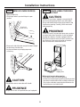
1
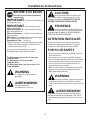
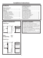
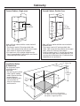
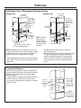
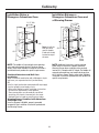
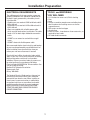
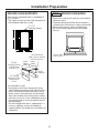
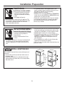
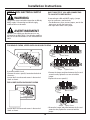
Installation
Instructions
If you have questions, call 800-GE-CARES or visit our website at: www.monogram.com
30" Convection
Built-In Ovens
Models:
ZET1038
ZET1058
Monogram.
®
We bring good things to life.
1
Installation Instructions
BEFORE YOU BEGIN
CAUTION:
Read these instructions completely
and carefully.
Due to the weight and size of these wall
ovens and to reduce the risk of personal injury or
damage to the product, TWO PEOPLE ARE REQUIRED FOR PROPER INSTALLATION.
IMPORTANT – Save these instructions for
local inspector’s use.
IMPORTANT
PRUDENCE
– Observe all governing
codes and ordinances.
Note to Installer – Be sure to leave these instructions with the Consumer.
Note to Consumer – Keep these instructions for
future reference.
Skill Level – Installation of these wall ovens requires
basic mechanical and electrical skills.
Completion Time – 1 to 3 hours.
• Proper installation is the responsibility of the installer.
Product failure due to improper installation is not
covered under the Warranty.
À cause du poids et des dimensions de ces
fours muraux et pour réduire les risques de blessures
et de dommages du produit, L’INSTALLATION DOIT
ÊTRE FAITE PAR DEUX PERSONNES.
ATTENTION INSTALLER
All electric wall ovens must be hard wired (direct
wired) into an approved junction box. A plug and
receptacle is NOT permitted on these products.
If you received a damaged oven, you should
immediately contact your dealer or builder.
FOR YOUR SAFETY
For Monogram local service in your area,
1-800-444-1845.
For Monogram service in Canada,
1-888-880-3030.
For Monogram Parts and Accessories, call
1-800-626-2002.
• The oven must be installed by a qualified installer or
service technician.
• Be sure the oven is securely installed in a cabinet
that is firmly attached to the house structure. Weight
on the oven door could cause the oven to tip and
result in injury. Never allow anyone to climb, sit,
stand or hang on the oven door.
• Make sure the cabinets and wall coverings around
the oven can withstand the temperatures (up to
200°F) generated by the oven.
WARNING
This appliance must be properly
grounded.
WARNING
The electrical power supply line to the oven
must be shut off while line connections are being
made. Failure to do so could result in serious injury or
death.
AVERTISSEMENT
Cet appareil doit être
correctement mis à la terre.
AVERTISSEMENT
Le circuit d’alimentation électrique du four doit être
hors tension pendant le branchement. Il faut suivre
cette directive pour éviter des blessures graves ou la
mort.
2
Installation Instructions
CONTENTS
Installation Preparation
Electrical Requirements ................................................... 7
Tools and Materials ......................................................... 7
Provide Oven Supports..................................................... 8
Step 1, Remove Packaging ............................................. 8
Installation Instructions
Step 2, Install Junction Box ............................................ 9
Step 3, 208V Electrical Supply ....................................... 10
Step 4, Remove Oven Door(s) ...................................... 11
Step 5, Route Cable Through Cutout ............................ 11
Step 6, Secure oven to Cabinet .................................... 12
Step 7, Replace oven Door ............................................ 12
Step 8, Connect Electrical ............................................. 13
Installation Checklist ...................................................... 14
Product Information
Product Dimensions .......................................................... 3
Advance Planning ............................................................ 3
Cabinetry
Framed Cabinet, Single Oven .......................................... 4
Framed Cabinet, Double Oven ........................................ 4
Installation Below a Countertop .................................... 4
Installation Over Warming Drawer ................................ 5
Frameless Cabinets ........................................................... 5
Installation Below Advantium ......................................... 6
Installation Between Advantium
and a Warming Drawer ............................................... 6
ADVANCE PLANNING
PRODUCT DIMENSIONS
Both single and double built-in ovens are available in a
European Style or Professional Style designs.
• These ovens are designed to fit in standard 30" wide
wall oven cabinets. The front face of the oven will be
nearly flush with cabinet doors. Professional style
oven doors are slightly thicker.
• Single ovens can be installed below a countertop or
below specific cooktop models listed on the label that
is located on the top of the oven case.
• Ovens are not approved for side-by-side or stackable
installations.
Single Ovens
A
21-1/4"
17-3/4"
1/2"
29-1/4"
23-1/4"
22-7/8"
22"
Models
ZET1038, ZET1058
ZET1038P, ZET1058P
Dim. A
2-7/8"
4-5/16"
Double Ovens
A
17-3/4"
21-1/4"
1/2"
29-1/4"
47-1/2"
48"
22"
3
Cabinetry
Framed Cabinet, Double Oven
Framed Cabinet, Single oven
23-1/2"
30"
28" Min.
28-3/8" Max.
23"
Max.
23-1/2"
Inside
28" Min.
28-3/8" Max.
47-5/8"
Min.
47-3/4"
Max.
34"
12"
30"
Order a 30" oven cabinet with the cutout sized to fit
the double oven.
• These ovens require 3/4" overlap on both sides.
Allow 1" Min. for top overlap and clearance to upper
doors. Allow 1/4" clearance at the bottom.
• Installing a double oven 12" from the floor will place
the base of the upper oven at countertop level. The
oven may be installed more than 12" above the floor,
depending on user preference.
Order a 30" oven cabinet with the cutout sized to fit
the single oven.
• These ovens require 3/4" overlap on both sides.
Allow 1" Min. for top overlap and clearance to upper
doors. Allow 1/4" clearance at the bottom.
• For single ovens, 34" installation height from the
floor is recommended. 34" will bring the oven floor to
countertop height when opened.
1-1/2" Cabinet Top
25"
Installation Below
A Countertop
The single oven may be
installed beneath a
countertop.
• The oven may be installed
below specific cooktop
models listed on the label
on top of the oven.
• Refer to cooktop installation instructions for
electrical requirements
and clearances.
36"
Countertop
Height
28" Min.
28-3/8" Max.
Oven
Junction
Box
23" Max.
23-1/2" Min.
Elevate the oven floor to desired height.
The support must be level, rigidly mounted
and capable of supporting 250 lbs.
4
Cabinetry
Installation Over a Monogram Warming Drawer
Single Oven
Double Oven
23-1/2" Min.
Inside
2x2 or 2x4
Anti-Tip Block
Against Rear
Wall, 9" From
Floor to
Bottom of
Block
23"
Max.
23-1/2" Min.
Inside
2x2 or 2x4
Anti-Tip Block
Against Rear
Wall, 9" From
Floor to
Bottom of
Block
47-5/8" Min.
47-3/4" Max.
2" Min.
9"
2" Min.
9-1/4"
28-1/2"
Allow 5/8"
Overlap on
All Sides
1" Min. Above Toekick or Adjust
to Oven Installation Height
9"
Note: Install the
oven only with
specific models
listed on the label
located on top of
the oven.
NOTE: Additional clearances between cutouts may
be required. Check to be sure the oven supports above
the Warming drawer location does not obstruct the
required interior 23-1/2" depth and 9-1/4" height.
9-1/4"
Allow 5/8"
Overlap on
All Sides
28-1/2
1" Min. Above Toekick
• The Monogram Warming Drawers require 5/8"
overlap on all sides.
• When installing a Monogram Warming Drawer below
a single or double oven, a separate 120V, 60 Hz,
properly grounded receptacle must be installed.
Refer to installation instructions packed with the
warming drawer for specific installation requirements.
• These Monogram Ovens require 3/4" overlap on both
sides. Allow 1" Min. for top overlap and clearance to
upper doors.
Frameless Cabinets
30"
Whenever possible, order 30" frameless cabinet with
the cutout sided to fit the oven. If using stock cabinets,
additional finished filler pieces may be required to
cover the opening.
• A stock frameless cabinet cutout width may be up to
28-3/4". If necessary, add 1/2" cleats to the sides,
flush with the front edge of the side panels to accept
mounting screws.
Install 1/2"
Cleats to
28" Min.
Hold Oven
28-3/8" Max.
Mounting
Double
Screws. 47-3/4" Max.
Single
23" Max.
Cabinet Depth
23-1/2" Min.
From Inside
Back to Front
of Cabinet Frame
or Side Panel.
3/4" Min.
Thick Bottom
Shelf Cut Back
Flush with Front
of Side Panel.
5
Cabinetry
Installation Below a
Monogram Advantium Oven
Installation Between a
Monogram Advantium Oven and
a Warming Drawer
23-1/2" Min.
Inside
23-1/2" Min.
Inside
21"
21"
2" Min.
2" Min.
23"
45-1/4"
28-1/2"
Note: Install the
oven only with
specific models
listed on the label
located on top of
the oven.
23"
45-1/4"
2" Min.
28-1/2"
9-1/4"
1" Min.
Above
Toekick
NOTE: Additional clearances may be required.
Check to be sure the oven supports above the
Warming Drawer does not obstruct the required
interior 23-1/2" depth and 9-1/4" height. The middle rail
separating the openings may need to be larger than
the 2" minimum shown. Always refer to the individual
installation instructions packed with each product for
specific requirements.
NOTE: The middle rail separating the two openings
may need to be larger than the 2" minimum shown.
Always refer to the individual installation instructions
packed with each product for specific requirements.
Combined Advantium and Wall Oven
Installation:
When installed in combination with a Monogram single
wall oven, use separate electrical junction boxes,
OR,
Install a single junction box connected to 50 amp supply
circuit or properly rated supply circuit.
• Refer to the Advantium oven installation instructions
for electrical requirements of that product.
• These connections must be made by a qualified
electrician. All electrical connections must meet
National Electrical code or prevailing local codes.
Warming Drawer Combined with Advantium
and Single Oven:
Install a separate 120V, 60Hz, properly grounded
receptacle. See installation Instructions packed with
the Warming Drawer.
6
Installation Preparation
ELECTRICAL REQUIREMENTS
TOOLS and MATERIALS
YOU WILL NEED
These Monogram built-in ovens require a separate
properly grounded 3-wire 120/208 or 120/240 volt, 60
Hz power supply, protected by a time delay fuse or
circuit breaker.
• Double ovens are rated at 6.5 KW at 240 volt and 6.5
KW at 208 volt.
• Single ovens are rated at 3.3 KW at 240 volt and 2.8
KW at 208 volt.
• Ovens are supplied with a flexible power cable
which must be attached to a junction box. The cable
length is 53" for both single and double convection
ovens.
• 2 X 4 Lumber for runners or 3/4" thick shelving
• Saw
• Level
• Phillips screwdriver, wood screws and adhesive or
other hardware for installing runners or shelf to
support the oven.
• Wire cutters and wire stripper
• Junction box
• Electrical cable - 3-conductor or 4-concuctor wire, as
required by local codes.
• UL listed conduit connector
• DO NOT use an extension cord with these appliances.
• DO NOT shorten the flexible power cable.
We recommend that the electrical wiring and hookup
of your oven be performed by a qualified electrician.
After installation, have the electrician show you
where your main oven disconnect is located.
Check with local utilities for electrical codes which
apply in your area. Failure to wire the oven according
to governing codes could result in a hazardous
condition. If there are no local codes, the oven must
be wired and fused in accordance with Nation
Electrical Code, ANSI/NFPA No. 70-latest edition. You
can get a copy by writing:
National Fire Protection Association
Batterymarch Park
Quincy MA 02269
The National Electrical Code requires that new, but
not existing construction utilize a four-conductor
connection to an electric oven. When installing an
electric oven in new construction, a mobile home,
recreational vehicle or an area where local codes
prohibit grounding through the neutral conductor,
follow instructions in the section on NEW CONSTRUCTION AND FOUR-CONDUCTOR BRANCH
CIRCUIT CONNECTION.
7
Installation Preparation
PROVIDE OVEN SUPPORTS
STEP 1 REMOVE PACKAGING
Ovens may be supported by either a solid bottom or
by 2 x 4 runners.
• The support must be level and rigidly mounted, flush
with the bottom edge of the cutout.
• Remove the carton, plastic coverings and styrofoam
side/corner posts.
• To prevent damage to the floor, do not remove the
styrofoam base until the oven is ready to be installed.
• Remove oven contents, shelves and packaging.
• Be sure to remove protective tape from the door
latch pin.
2"x 4" or
Equivalent Runners
24"
25"
30"
Remove Tape
From Latch Pin
Level with Bottom
Edge of Cutout and Flush
with Cabinet Front
3/4" Min.
Sheeting (Plywood
or Wafer Board
Sourced on Site)
Interior
Cabinet
Width
Interior
Cabinet
Depth
Height
as Required
3/4" Sheeting
(Plywood or Wafer
Board Sourced
on Site)
If a solid bottom is used:
• Cut two pieces of 3/4" thick sheeting to fit inside
cabinet depth and available inside cabinet height. If
there is no interference below the cutout, such as
drawer runners, the sheeting can rest on the floor.
Secure the sheeting strips or pieces to the cabinet
walls with screws. Lay 2 x 4 or solid bottom on top of
the sheeting and drive screws through the top and
into the sheeting.
• The entire weight of the oven is supported by 2 x 4
runners or solid floor and must be capable of
supporting 350 lbs. For double ovens and 250 lbs. For
single ovens.
8
Installation Preparation
WARNING
• If a cold water pipe is interrupted by plastic, nonmetallic gaskets, union connections or other insulating materials, DO NOT use for grounding.
• DO NOT ground to a gas pipe.
• DO NOT have a fuse in the NEUTRAL or GROUNDING
circuit. A fuse in the NEUTRAL or GROUNDING circuit
could result in an electrical shock.
• Check with a qualified electrician if you are in doubt
as to whether the appliance is properly grounded.
Failure to follow these instructions could result in
serious injury or death.
ELECTRICAL SHOCK HAZARD
• The electrical power to the oven
branch circuit must be shut-off
while line connections are being
made.
• Use copper wiring only.
• Electrical ground is required on this appliance. The
free end of the green wire (the ground wire) must be
connected to a suitable ground. This wire must
remain grounded to the oven.
ADVERTISSEMENT
• NE PAS utiliser pour la mise à la terre un tuyau d’eau
froide interrompu par du plastique, des joints ou des
raccords non-métalliques, ou autre matériel isolant.
• NE PAS mettre à la terre sur un tuyau de gaz.
• NE PAS utiliser de fusible sur le circuit de NEUTRE ou
de MISE À LA TERRE. Un fusible dans le circuit de
NEUTRE ou de MISE À LA TERRE peut causer un
choc électrique.
• En cas de doute, faire vérifier la mise à la terre de
l’appareil par un électricien qualifié.
Il faut suivre ces instructions pour éviter des blessures
graves ou la mort.
RISQUE DE CHOC ÉLECTRIQUE
• Le circuit d’alimentation du four doit
être hors tension pendant le
branchement.
• Utiliser uniquement des fils en
cuivre.
• Cet appareil doit être mis à la terre. L’extrémité du fil
vert (le fil de mise à la terre) doit être branchée à
une terre appropriée. Ce fil doit rester branché au
four.
STEP 2 INSTALL JUNCTION BOX
The conduit is located in the center at the top rear of
the oven.
• Locate and install the junction box within reach of
the power cable.
• Install the junction box in an adjacent left or right
cabinet, below the cutout floor, or in the top cabinet
above the cutout.
47-3/4"
Max.
9
23"
Max.
Installation Instructions
SKIP THIS STEP IF YOU ARE CONNECTING
TO 240 VOLT POWER SUPPLY.
STEP 3 208V ELECTRICAL SUPPLY
WARNING
If connecting to a 208 volt, 60 HZ supply, a jumper
must be used across two terminals.
• For double ovens, there are two jumpers, one for the
upper oven, one for the lower oven.
• For single ovens there is one jumper.
These ovens are pre-wired for connection to 240 volt,
60 HZ, supply. If connecting to a 208 volt supply,
modifications must be made.
AVERTISSEMENT
Ces fours sont câblés pour branchement sur une
alimentation en 240 V, 60 Hz. Il faut faire des modifications en cas de branchement sur une alimentation en
208 V.
FOR SINGLE OVENS, UPPER OVEN ON DOUBLE OVENS
Jumper
1
Jump
Loosen Screws
2
3
4
5
Loosen Screws
Jumper
To connect to 208V circuit:
• Remove the access panel(s) located on the back of
the ovens.
• Loosen the first and second screws in the terminal
block as shown.
Tighten Screws
• Remove the jumper and place between the first and
second screws, tighten the screws to hold the
jumper.
• Replace the access panel(s).
FOR LOWER OVEN ON DOUBLE OVENS
1
2
3
Jumper
Loosen Screws
4
Jumper
Loosen Screws
Jumper Tighten Screws
• Remove the jumper and place between the first and
second screws, tighten the screws to hold the
jumper.
• Loosen the first and second screws in the terminal
block as shown.
10
Installation Instructions
STEP 4 REMOVE OVEN DOOR(S)
STEP 5 ROUTE CABLE THROUGH
CUTOUT
• Open the door fully.
• Push hinge latches up to lock hinges in open
position.
CAUTION
Oven(s) are very heavy. 2 people are required to lift
oven(s) into the opening. Ovens have side handles.
Grasp side handle with one hand and put other hand
into the oven opening. Carefully, lift the oven to the
cabinet opening.
Hinge Latch
Normal Position
PRUDENCE
Le four est lourd. Il faut deux personnes pour soulever
et mettre le four dans l’ouverture. Le four est équipé
de poignées latérales. Prendre la poignée latérale
d’une main et mettre l’autre main dans l’ouverture du
four. Soulever le four avec précaution et le mettre
dans l’ouverture de l’armoire de cuisine.
• Grasp each side of the door and pull the door straight
out and away from the oven.
• Lay the oven door on packaging to prevent
scratching.
Locked
Hinge
Latch
Styrofoam
Shipping Base
With oven in front of cabinet opening:
• Insert power cable into cabinet opening.
• Lift the oven into the opening while continuing to feed
the cable in the direction of the installed junction box.
Be sure the cable does not get pinched between the
back of the oven and cabinet wall.
CAUTION
Do not lift the oven or oven door with handle.
PRUDENCE
Ne pas lever le four ou la porte du four par la poignée.
11
Installation Instructions
STEP 6 SECURE OVEN TO
CABINET
STEP 7 REPLACE OVEN DOOR
• Grasp door firmly on both sides.
• Slide the hinge slots in the bottom of the door over
the hinges.
• Push the door all the way in, against the oven.
• Slide oven into cabinet opening.
• Drill 3/32" pilot holes through the oven front frame
and into the cabinet frame.
Locked
Hinge
Latch
Secure Oven to
Cabinet with
Screws Provided
• Secure oven to cabinet with screws provided. Single
ovens use 2 screws, one on each side. Double ovens
use 4 screws, 2 on each side.
• Open the door fully and push hinge latches down,
as illustrated, on both sides to secure.
• Close the door and open slowly to be sure it moves
smoothly.
WARNING
Securely fasten oven to cabinet using the screws
provided. Failure to do so could cause the oven to
move or tip during use and result in personal injury.
AVERTISSEMENT
Monter fermement le four sur l’armoire de cuisine
avec les vis fournies. Si le four n’est pas monté
fermement, il peut se déplacer ou basculer pendant
l’usage et causer des blessures.
12
Installation Instructions
STEP 8 CONNECT ELECTRICAL
AVERTISSEMENT
WARNING
RISQUE DE CHOC
ÉLECTRIQUE
• Cet appareil doit être mis à la
terre.
• NE PAS brancher l’alimentation
électrique si l’appareil n’est pas
ELECTRICAL SHOCK HAZARD
• Electrical ground is required on
this appliance.
• DO NOT connect to the electrical
supply until appliance is permanently grounded.
• Disconnect power to the junction box before
making the electrical connection.
• This appliance must be connected to a grounded,
metallic, permanent wiring system or a grounding
connector should be connected to the grounding
terminal or wire lead on the appliance.
Failure to do so could result in fire, personal injury or
electrical shock.
mis à la terre de façon permanente.
• Débrancher l’alimentation au boîtier de
raccordement avant de faire le branchement
électrique.
• Cet appareil doit être branché sur un circuit permanent métallique à la terre ou un connecteur de mise
à la terre doit être branché à la borne de mise à la
terre ou un fil de l’appareil.
Il faut suivre ces instructions pour éviter des
incendies, des blessures graves ou la mort.
3-Conductor Branch Circuit
120V AC
Neutral
4-Conductor Branch Circuit
Branch Circuit
Oven
Red
Red
White or
Gray
Green
120V AC
120V AC
Branch Circuit
Oven
Red
Red
Black
Black
Bare or
Green
Green
White or
Gray
White
White
120V AC
Black
Black
GND
When connecting to a 3-conductor branch
circuit:
• Connect oven red lead to branch circuit red lead.
• Connect oven black lead to branch circuit black
lead.
• Connect oven bare copper conductor and white lead
to branch circuit neutral lead (white or gray).
Neutral
When connecting to a 4-conductor branch
circuit:
• Connect oven red lead to branch circuit red lead.
• Connect oven black lead to branch circuit black
lead.
• Break connection between oven white lead and
oven bare copper conductor.
• Connect oven white lead to branch circuit neutral
lead (white or gray).
• Connect oven bare copper conductor to branch
circuit ground lead (green or bare copper).
Note: Use copper wire only.
13
Installation Instructions
INSTALLATION CHECKLIST
1. Turn all knobs to OFF or Normal.
2. Turn on power at the circuit breaker.
3. Set the clock for current time of day. Refer to the
Owner’s Manual for instructions.
4. Check oven door for full opening and closing. Oven
lights should be on when the door is opened and off
when the door is closed.
14
Notes
15
Note: While performing installations described in this book,
safety glasses or goggles should be worn.
For Monogram® local service in your area, call
1-800-444-1845.
Note: Product improvement is a continuing endeavor at
General Electric. Therefore, materials, appearance and
specifications are subject to change without notice.
Monogram.
®
We bring good things to life.
GE Consumer Products
General Electric Company
Louisville, KY 40225
© 2003 General Electric Company
Pub. No. 49-80188
Dwg. No. 164D4290P344
(N.D. 625) 2/03
Printed in Italy
16