1
OC375A--1.qxp
07.1.22 2:15 PM
Page 1
SPLIT-TYPE, HEAT PUMP AIR CONDITIONERS
January 2007
No. OC375
REVISED EDITION-A
TECHNICAL & SERVICE MANUAL
Indoor unit
[Model names]
Revision:
• RoHS PARTS LIST is added.
• Service Ref. of outdoor unit
has been modified.
• Some descriptions have
been modified.
[Service Ref.]
PCH-2GAK
PCH-2.5GAK
PCH-3GAK
PCH-4GAK
PCH-5GAK
PCH-6GAK
PCH-2GAKH
PCH-2.5GAKH
PCH-3GAKH
PCH-4GAKH
PCH-5GAKH
PCH-6GAKH
PCH-2GAK
PCH-2.5GAK
PCH-3GAK
PCH-4GAK
PCH-5GAK
PCH-6GAK
PCH-2GAKH
PCH-2.5GAKH
PCH-3GAKH
PCH-4GAKH
PCH-5GAKH
PCH-6GAKH
• Please void OC375.
Note:
• This manual describes only
service data of the indoor
units.
• RoHS compliant products
have <G> mark on the
spec name plate.
• For servicing of RoHS
compliant products, refer
to the RoHS Parts List.
CONTENTS
INDOOR UNIT
TEMP.
ON/OFF
REMOTE CONTROLLER
Model name
indication
1. REFERENCE MANUAL ······································2
2. PART NAMES AND FUNCTIONS ···················3
3. SPECIFICATIONS ············································5
4. DATA·······························································13
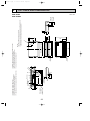
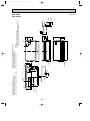
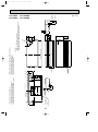
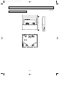
5. OUTLINES AND DIMENSIONS ·····················23
6. WIRING DIAGRAM············································28
7. REFRIGERANT SYSTEM DIAGRAM ··················29
8. TROUBLESHOOTING ···································31
9. FUNCTION SETTING·····································44
10. SYSTEM CONTROL ·····································50
11. DISASSEMBLY PROCEDURE·······················64
12. PARTS LIST ···················································69
13. RoHS PARTS LIST ········································78
14. OPTIONAL PARTS ········································87
OC375A--1.qxp
1
07.1.22 2:15 PM
Page 2
REFERENCE MANUAL
1-1. OUTDOOR UNIT’S SERVICE MANUAL
Service Ref.
Service Manual No.
PUH-2/2.5AKA1.TH-A, PUH-2/2.5AKA2.TH-A
PUH-3VKA2.TH-A, PUH-3VKA3.TH-A
PUH-3YKA1.TH-A, PUH-3YKA2.TH-A
PUH-4YKSA1.TH-A
PUH-5/6YKSA3.TH-A, PUH-5/6YKSA4.TH-A
PUH-2/2.5/3VKA.TH, PUH-2/2.5/3VKA1.TH
PUH-3YKA.TH, PUH-3YKA1.TH
PUH-4/5/6YKSA.TH, PUH-5/6YKSA1.TH
PUH-2/2.5/3NKA.TH, PUH-2/2.5/3NKA1.TH
PUH-4/5/6TKSA.TH, PUH-5/6TKSA1.TH
OC156
OC325
OC354
2
OC375A--1.qxp
07.1.22 2:15 PM
2
Page 3
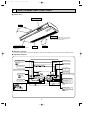
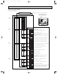
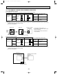
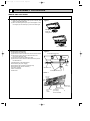
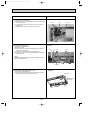
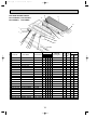
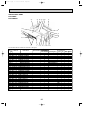
PART NAMES AND FUNCTIONS
● Indoor Unit
Left/right guide vanes
Change the direction of airflow
from the horizontal blower.
Air outlet
Long-life filter
Removes dust and foreign matter from air coming in
through the grille (Recommended cleaning interval :
Approx, every 2,500 operating hours)
Up/down guide vanes
Change the direction of airflow from the
vertical blower.
Air intake
Intake grille
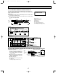
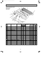
● Remote controller
Once the controls are set, the same operation mode can be repeated by simply pressing the ON/OFF button.
● Operation buttons
ON/OFF button
Set Temperature buttons
Down
Fan Speed button
Up
Timer Menu button
(Monitor/Set button)
Filter
button
(<Enter> button)
Mode button (Return button)
TEMP.
ON/OFF
Set Time buttons
Check button (Clear button)
Back
Ahead
Test Run button
MENU
BACK
MONITOR/SET
ON/OFF
FILTER
DAY
CHECK TEST
Airflow Up/Down button
Timer On/Off button
(Set Day button)
PAR-21MAA
CLOCK
OPERATION
CLEAR
Louver button
Operation button)
(
To return operation
number
Opening the
door
Ventilation button
Operation button)
(
To go to next operation
number
3
OC375A--1.qxp
07.1.22 2:15 PM
Page 4
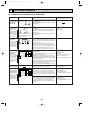
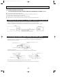
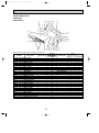
● Display
“Sensor” indication
Displayed when the remote controller
sensor is used.
Day-of-Week
For purposes of this explanation,
all parts of the display are shown
as lit. During actual operation, only
the relevant items will be lit.
Shows the current day of the week.
Time/Timer Display
“Locked” indicator
Shows the current time, unless the simple or Auto Off
timer is set.
If the simple or Auto Off timer is set, shows the time
remaining.
Indicates that remote controller buttons have been locked.
Identifies the current operation
“Clean The Filter” indicator
Shows the operating mode, etc.
* Multilanguage display is supported.
Comes on when it is time to clean the
filter.
TIME SUN MON TUE WED THU FRI SAT
TIMER
Hr
ON
AFTER
FUNCTION
FILTER
˚F˚C
“Centrally Controlled” indicator
Indicates that operation of the remote controller has been prohibited by a master controller.
Timer indicators
AFTER OFF
ERROR CODE
˚F˚C
The indicator comes on if the corresponding timer is set.
WEEKLY
SIMPLE
AUTO OFF
ONLY1Hr.
Fan Speed indicator
Shows the selected fan speed.
“Timer Is Off” indicator
Indicates that the timer is off.
Temperature Setting
Shows the target temperature.
Up/Down Air Direction indicator
Room Temperature display
Shows the room temperature.
The indicator
shows the direction of the outcoming airflow.
Louver display
“One Hour Only” indicator
Indicates the action of the swing
louver. Does not appear if the
louver is stationary.
Displayed if the airflow is set to
Low and downward during COOL
or DRY mode. (Operation varies
according to model.)
The indicator goes off after one
hour when the airflow direction
also changes.
Ventilation indicator
Appears when the unit is running in
Ventilation mode.
(Power On indicator)
Indicates that the power is on.
Caution
● Only the Power on indicator lights when the unit is stopped and power supplied to the unit.
● If you press a button for a feature that is not installed at the indoor unit, the remote controller will display the “Not Available”
message.
If you are using the remote controller to drive multiple indoor units, this message will appear only if the feature is not
present at the parent unit.
● When power is turned ON for the first time, it is normal that “PLEASE WAIT” is displayed on the room temperature indication (For max. 2minutes). Please wait until this “PLEASE WAIT” indication disappear then start the operation.
4
OC375A--1.qxp
07.1.22 2:15 PM
3
Page 5
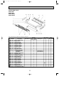
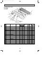
SPECIFICATIONS
Rating Conditions (JIS B8616)
Service Ref.
Item
PCH-2GAK(H)
Btu/h
W
kW
Capacity
Total input
Service Ref.
Power supply
Input
Running current
Starting current
External finish
Heat exchanger
Fan(drive))No.
Fan motor output
Airflow(Low-High)
External static pressure
Booster heater
Operation control & Thermostat
Noise level(Low-High)
Cond. drain connection O.D.
kW
A
A
INDOOR UNIT
OUTDOOR UNIT
Dimensions
Weight
Service Ref.
Power supply
Input
Running current
Starting current
External finish
Refrigerant control
Compressor
Model
Motor output
Starter type
Protection devices
Heat exchanger
Fan(drive))No.
Fan motor output
Airflow
Defrost method
Crankcase heater
Noise level
Dimensions
REFRIGERANT
PIPING
kW
K/min <CFM>
Pa(mmAq)
kW
W
D
H
dB(A)
mm,(in)
mm,(in)
mm,(in)
mm,(in)
kg,(lbs)
kW
A
A
kW
kW
K/min <CFM>
W
D
H
Weight
Refrigerant
Charge
W
dB(A)
mm,(in)
mm,(in)
mm,(in)
kg,(lbs)
kg,(lbs)
mm,(in)
Liquid
Pipe size O.D.
mm,(in)
Gas
Indoor side
Connection method
Outdoor side
Height difference
Between the indoor & outdoor unit
Piping length
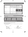
Notes1. Rating Conditions (JIS B8616)
Cooling : Indoor : 27:(80oF)DB. 19:(66oF)WB
Outdoor : 35:(95oF)DB. 24:(75oF)WB
Heating : Indoor : 20:(68oF)DB.
Outdoor : 7:(45oF)DB. 6:(43oF)WB
Refrigerant piping length (one way) : 5m(16ft)
PCH-2.5GAK(H)
Cooling
Heating
Cooling
Heating
18,400
21,200 (25,900)
23,900
24,200 (31,400)
5,400
6,200 (7,600)
7,000
7,100 (9,200)
2.30
2.32 (3.72)
2.59
2.36 (4.46)
PCH-2GAK(H)
PCH-2.5GAK(H)
Single phase. 50Hz. 220-240V
0.10
0.10 (1.50)
0.13
0.13 (2.23)
0.43
0.43(6.21)
0.55
0.55 (9.30)
1.20
1.20 (6.98)
1.27
1.27 (10.02)
Munsell 0.70Y 8.59 / 0.97
Plate fin coil
Sirocco (direct)O2
Sirocco (direct)O3
0.054
0.07
10 -13 <353-459>
14 -18 <494-635>
0 (direct blow)
(1.4)
(2.1)
Remote controller & built-in
37 - 42
37 - 43
26(1)
1,000 (39-3/8)
1,310 (51-9/16)
680 (26-3/4)
210 (8-1/4)
34 (75) [36 (79)]
27 (60) [28.5 (63)]
PUH-2.5VKA1.TH
PUH-2VKA1.TH
Single phase. 50Hz. 220-240V
2.20
2.22
2.46
2.23
9.86
9.95
10.68
9.78
45
45
52
52
Munsell 3.0Y 7.8/1.1
Capillary tube
Hermetic
NH38VMDT
NH41VMDT
1.7
2.0
Line start
Internal thermostat. High-pressure switch
Plate fin coil
Propeller (direct)✕1
0.065
0.085
45 (1,590)
50 (1,764)
Reverse cycle
38
49
52
870 (34-1/4)
295 + 24 (11-5/8 add 1)
650 (25-5/8)
850 (33-7/16)
64 (141)
68 (150)
R-22
2.2 (4.9)
2.8 (6.2)
9.52 (3/8)
15.88 (5/8)
Flared
Flared
Max. 40m
Max. 50m
Max. 40m
Max. 50m
Function
2. Guaranteed operating range
Cooling
Heating
3. Above data based on indicated voltage
Indoor Unit 1 phase 240V 50Hz
Outdoor Unit 1 phase 240V 50Hz
5
Upper limit
Lower limit
Upper limit
Lower limit
Indoor
Outdoor
35: DB, 22.5: WB
46: DB
21: DB, 15.5: WB
-5: DB
27: DB
21: DB, 15.5: WB
20: DB
-8.5: DB, -9.5: WB
OC375A--1.qxp
07.1.22 2:15 PM
Page 6
Rating Conditions (JIS B8616)
Service Ref.
Item
Function
Btu/h
W
kW
Capacity
Total input
Service Ref.
Power supply
Input
Running current
Starting current
External finish
Heat exchanger
Fan(drive))No.
Fan motor output
Airflow(Low-High)
External static pressure
Booster heater
Operation control & Thermostat
Noise level(Low-High)
Cond. drain connection O.D.
INDOOR UNIT
kW
A
A
OUTDOOR UNIT
REFRIGERANT
PIPING
kW
K/min (CFM)
Pa(mmAq)
kW
Weight
Service Ref.
Power supply
Input
Running current
Starting current
External finish
Refrigerant control
Compressor
Model
Motor output
Starter type
Protection devices
Heat exchanger
Fan(drive))No.
Fan motor output
Airflow
Defrost method
Crankcase heater
Noise level
Dimensions
dB(A)
mm,(in)
mm,(in)
mm,(in)
mm,(in)
kg,(lbs)
kW
A
A
kW
kW
K/min (CFM)
W
D
H
Weight
Refrigerant
Charge
W
dB(A)
mm,(in)
mm,(in)
mm,(in)
kg,(lbs)
kg,(lbs)
Liquid
mm,(in)
Pipe size O.D.
Gas
mm,(in)
Indoor side
Connection method
Outdoor side
Height difference
Between the indoor & outdoor unit
Piping length
Notes1. Rating Conditions
Cooling : Indoor : D.B.
Outdoor : D.B.
Heating : Indoor : D.B.
Outdoor : D.B.
Refrigerant piping length
PCH-2.5GAK
Heating
21,300
6,250
2.29
PCH-2GAK
W
D
H
Dimensions
PCH-2GAK
Cooling
18,100
5,300
2.28
27:(80oF) W.B. 19:(66oF)
35:(95oF) W.B. 24:(75oF)
20:(68oF)
7:(45oF) W.B. 6:(43oF)
(one way) : 5m(16ft)
3. Above data based on indicated voltage
Indoor Unit 1 phase 240V 50Hz
Outdoor Unit 1 phase 240V 50Hz
Cooling
23,200
6,800
2.53
Heating
24,200
7,100
2.33
PCH-2.5GAK
Single phase. 50Hz. 240V
0.10
0.13
0.13
0.43
0.55
0.55
1.20
1.27
1.27
Munsell 0.70Y 8.59 / 0.97
Plate fin coil
Sirocco (direct))2
Sirocco (direct))3
0.054
0.07
10 -13 (353-459)
14 -18 (494-635)
0 (direct blow)
–
–
Remote controller & built-in
37 - 42
37 - 43
26 (1)
1,000 (39-3/8)
1,310 (51-9/16)
680 (26-3/4)
210 (8-1/4)
34 (75)
27 (60)
PUH-2.5AKA2.TH-A
PUH-2AKA2.TH-A
Single phase. 50Hz. 240V
2.18
2.19
2.40
2.20
9.77
9.81
10.20
9.75
45
45
45
45
Munsell 3.0Y 7.8/1.1
Capillary tube
Hermetic
NH38AMDT
NH41AMDT
1.7
2.0
Line start
Internal thermostat. High-pressure switch
Plate fin coil
Propeller (direct))1
0.065
0.085
45 (1,590)
50 (1,764)
Reverse cycle
38
49
52
870 (34-1/4)
295 + 24 <11-5/8 add 1>
650 (25-5/8)
850 (33-7/16)
64 (141)
68 (150)
R-22
2.7 (6.0)
2.8 (6.2)
9.52 (3/8)
15.88 (5/8)
Flared
Flared
Max. 40m
Max. 50m
Max. 40m
Max. 50m
0.10
0.43
1.20
2. Guaranteed operating range
Cooling
Heating
6
Upper limit
Lower limit
Upper limit
Lower limit
Indoor
Outdoor
D.B. 46:
D.B. 35: W.B. 22.5:
D.B. -5:
D.B. 21: W.B. 15.5:
D.B. 21: W.B.15.5:
D.B. 27:
D.B.-8.5: W.B.-9.5:
D.B. 20:
OC375A--1.qxp
07.1.22 2:15 PM
Page 7
Rating Conditions (JIS B8616)
Service Ref.
Item
Function
Btu/h
W
kW
Capacity
Total input
Service Ref.
Power supply
Input
Running current
External finish
Heat exchanger
Fan(drive))No.
Fan motor output
Airflow(Low-High)
External static pressure
Booster heater
Operation control & Thermostat
Noise level(Low-High)
Cond. drain connection O.D.
INDOOR UNIT
kW
A
OUTDOOR UNIT
Dimensions
W
D
H
Weight
Service Ref.
Power supply
Input
Running current
Starting current
External finish
Refrigerant control
Compressor
Model
Motor output
Starter type
Protection devices
Heat exchanger
Fan(drive))No.
Fan motor output
Airflow
Defrost method
Crankcase heater
Noise level
Dimensions
REFRIGERANT
PIPING
kW
K/min (CFM)
Pa(mmAq)
kW
Weight
Refrigerant
Charge
dB(A)
mm,(in)
mm,(in)
mm,(in)
mm,(in)
kg,(lbs)
kW
A
A
kW
kW
K/min (CFM)
W
D
H
W
dB(A)
mm,(in)
mm,(in)
mm,(in)
kg,(lbs)
kg,(lbs)
Liquid
mm,(in)
Pipe size O.D.
Gas
mm,(in)
Indoor side
Connection method
Outdoor side
Height difference
Between the indoor & outdoor unit
Piping length
Notes : w1. Rating conditions (JIS 8616)
(INDOOR)
Cooling : D.B. 27: W.B. 19:
(OUTDOOR) Cooling : D.B. 35:
w2. Rating conditions (SSA 385)
(INDOOR)
Cooling : D.B. 29: W.B.19:
(OUTDOOR) Cooling : D.B. 46:
PCH-2GAK
PCH-2.5GAK
Cooling w1/w2
Heating w2
Cooling w1/w2
Heating w2
18,100 / 15,000
21,300
23,900 / 20,500
27,300
5,300 / 4,400
6,250
7,000 / 6,000
8,000
2.54 / 2.96
2.58
3.06 / 3.58
2.95
PCH-2GAK
PCH-2.5GAK
Single phase. 60Hz. 220V
0.13
0.13
0.15
0.15
0.61
0.61
0.70
0.70
Munsell 0.70Y 8.59 / 0.97
Plate fin coil
Sirocco (direct)O2
Sirocco (direct)O3
0.054
0.07
10 -13 (353-459)
14 -18 (494-635)
0 (direct blow)
–
–
Remote controller & built-in
37 - 42
37 - 43
26(1)
1,000 (39-3/8)
1,310 (51-9/16)
680 (26-3/4)
210 (8-1/4)
34(75)
27(60)
PUH-2.5NKA1.TH
PUH-2NKA1.TH
Single phase. 60Hz. 220V
2.41 / 2.83
2.45
2.91 / 3.43
2.80
11.07 / 12.99
11.2
13.50 / 15.75
13.0
45
45
58
58
Munsell 3.0Y 7.8/1.1
Capillary tube
Hermetic
NHJ33NBDT
NHJ38NBDT
1.5
1.7
Line start
Internal thermostat. High-pressure switch
Plate fin coil
Propeller (direct)✕1
0.065
0.085
45 (1,590)
50 (1,764)
Reverse cycle
38
49
52
870 (34-1/4)
295 + 24 (11-5/8 add 1)
650 (25-5/8)
850 (33-7/16)
66.5 (147)
74 (163)
R-22
2.2 (4.9)
2.8 (6.2)
9.52 (3/8)
15.88 (5/8)
Flared
Flared
Max. 40m
Max. 50m
Max. 40m
Max. 50m
Heating : D.B. 21:
Heating : D.B. 7:
7
D.B. 6:
OC375A--1.qxp
07.1.22 2:15 PM
Page 8
Rating Conditions (JIS B8616)
Service Ref.
Item
PCH-3GAK
Cooling
25,900
7,600
3.28
Function
Btu/h
W
kW
Capacity
Total input
Service Ref.
Power supply
Input
Running current
Starting current
External finish
Heat exchanger
Fan(drive))No.
Fan motor output
Airflow(Low-High)
External static pressure
Booster heater
Operation control & Thermostat
Noise level(Low-High)
Cond. drain connection O.D.
PCH-3GAK
Single phase. 50Hz.220-240V
INDOOR UNIT
kW
A
A
OUTDOOR UNIT
Weight
Service Ref.
Power supply
Input
Running current
Starting current
External finish
Refrigerant control
Compressor
Model
Motor output
Starter type
Protection devices
Heat exchanger
Fan(drive))No.
Fan motor output
Airflow
Defrost method
Crankcase heater
Noise level
REFRIGERANT
PIPING
Dimensions
Weight
Refrigerant
Charge
0.13
0.55
1.27
dB(A)
mm,(in)
mm,(in)
mm,(in)
mm,(in)
kg,(lbs)
kW
A
A
kW
VKA-A...Inner thermostat. High-pressure switch YKA-A...Anti-phase protector, Thermal relay, thermal switch, High-pressute switch
Plate fin coil
Propeller (direct)O1
0.085
50 (1,764)
Reverse cycle
38
52
870 (34-1/4)
295 + 24 (11-5/8 add 1)
850 (33-7/16)
75 (165)
R-22
3.2 (7.1)
9.52 (3/8)
15.88 (5/8)
Flared
Flared
Max. 50m
Max. 50m
kW
K/min (CFM)
W
D
H
W
dB(A)
mm,(in)
mm,(in)
mm,(in)
kg,(lbs)
kg,(lbs)
Liquid
mm,(in)
Pipe size O.D.
Gas
mm,(in)
Indoor side
Connection method
Outdoor side
Height difference
Between the indoor & outdoor unit
Piping length
Notes1. Rating Conditions
Cooling : Indoor : D.B.
Outdoor : D.B.
Heating : Indoor : D.B.
Outdoor : D.B.
Refrigerant piping length
0.13
0.55
1.27
Munsell 0.70Y 8.59 / 0.97
Plate fin coil
Sirocco (direct)O3
0.070
14 -18 (494-635)
0 (direct blow)
–
Remote controller & built-in
37 - 43
26 (1)
1,310(51-9/16)
680 (26-3/4)
210(8-1/4)
34 (75)
PUH-3VKA1.TH, PUH-3VKA3.TH-A/ PUH-3YKA1.TH, PUH-3YKA2.TH-A
VKA...1phase, 50Hz, 220-240V / YKA...3phase, 50Hz, 400-415V, 4wires
3.15
2.94
13.82 / 5.16
12.89 / 4.81
58 / 37
58 / 37
Munsell 3.0Y 7.8/1.1
Capillary tube
Hermetic
NH52VNHT/ NH52YDAT
2.2/ 2.4
Line start
kW
K/min (CFM)
Pa(mmAq)
kW
W
D
H
Dimensions
Heating
29,000
8,500
3.07
27:(80oF) W.B. 19:(66oF)
35:(95oF) W.B. 24:(75oF)
20:(68oF)
7:(45oF) W.B. 6:(43oF)
(one way) : 5m(16ft)
2. Guaranteed operating range
3. Above data based on indicated voltage
Indoor Unit 1 phase 240V 50Hz
Outdoor Unit 1 phase 240V 50Hz / 3 phase 415V 50Hz
Cooling
Heating
8
Upper limit
Lower limit
Upper limit
Lower limit
Outdoor
Indoor
D.B. 46:
D.B. 35: W.B. 22.5:
D.B. -5:
D.B. 21: W.B. 15.5:
D.B. 21: W.B.15.5:
D.B. 27:
D.B.-8.5: W.B.-9.5:
D.B. 20:
OC375A--1.qxp
07.1.22 2:15 PM
Page 9
Rating Conditions (JIS B8616)
Service Ref.
Item
Function
Btu/h
W
kW
Capacity
Total input
Service Ref.
Power supply
Input
Running current
Starting current
External finish
Heat exchanger
Fan(drive))No.
Fan motor output
Airflow(Low-High)
External static pressure
Booster heater
Operation control & Thermostat
Noise level(Low-High)
Cond. drain connection O.D.
INDOOR UNIT
kW
A
A
OUTDOOR UNIT
Dimensions
W
D
H
Weight
Service Ref.
Power supply
Input
Running current
Starting current
External finish
Refrigerant control
Compressor
Model
Motor output
Starter type
Protection devices
Heat exchanger
Fan(drive))No.
Fan motor output
Airflow
Defrost method
Crankcase heater
Noise level
Dimensions
REFRIGERANT
PIPING
kW
K/min <CFM>
Pa(mmAq)
kW
Weight
Refrigerant
Charge
dB(A)
mm,(in)
mm,(in)
mm,(in)
mm,(in)
kg,(lbs)
kW
A
A
kW
PCH-3GAK(H)
PCH-4GAK(H)
Cooling
Heating
Cooling
Heating
25,600
29,000 (36,200)
34,100
35,700 (44,900)
7,500
8,500 (10,600)
10,000
10,450 (13,150)
3.28
3.07 (5.17)
3.36
3.35(6.05)
PCH-3GAK(H)
PCH-4GAK(H)
Single phase. 50Hz. 220-240V
0.13
0.13 (2.23)
0.16
0.16 (2.86)
0.55
0.55 (9.30)
0.70
0.70 (11.95)
1.27
1.27 (10.02)
1.48
1.48 (12.73)
Munsell 0.70Y 8.59 / 0.97
Plate fin coil
Sirocco (direct) O 3
0.07
0.09
14 -18 <494-635>
20 -25 <706-883>
0 (direct blow)
(2.1)
(2.7)
Remote controller & built-in
37 - 43
40 - 45
26 (1)
1,310 ( 51-9/16 )
680 (26-3/4)
210 (8-1/4)
270 (10-5/8)
37 (82) [39.5 (87)]
34 (75) [36 (79)]
PUH-4YKSA.TH, PUH-4YKSA1.TH-A
PUH-3VKA1.TH/ PUH-3YKA1.TH
VKA...1phase, 50Hz, 220-240V / YK(S)A...3phase, 50-380Hz, 415V, 4wires
3.15
2.94
3.20
3.19
13.82 / 5.16
12.89 / 4.81
5.24
5.22
58 / 37
58 / 37
40
40
Munsell 3.0Y 7.8/1.1
Capillary tube
Hermetic
NH52VNHT/ NH52YDAT
NH56YDAT
2.2 / 2.4
2.7
Line start
VKA...Inner thermostat. High-pressure switch YKA...Anti-phase protector, Thermal relay, Thermal switch, High-pressute switch
Plate fin coil
Propeller (direct) O 1
0.085
50 (1,764)
kW
K/min <CFM>
Propeller (direct) O 2
0.065 + 0.065
95 (3,350)
Reverse cycle
W
D
H
38
52
W
dB(A)
mm,(in)
mm,(in)
mm,(in)
kg,(lbs)
870 <34-1/4>
295 + 24 <11-5/8 add 1>
850 (33-7/16)
75 (165)
1,258 (49-1/2)
94 (207)
R-22
3.2 (7.1)
9.52 (3/8)
15.88 (5/8)
kg,(lbs)
Liquid
mm,(in)
Pipe size O.D.
Gas
mm,(in)
Indoor side
Connection method
Outdoor side
Height difference
Between the indoor & outdoor unit
Piping length
Notes1. Rating Conditions (JIS B8616)
Cooling : Indoor : 27:(80oF)DB. 19:(66oF)WB
Outdoor : 35:(95oF)DB. 24:(75oF)WB
Heating : Indoor : 20:(68oF)
Outdoor : 7:(45oF)DB. 6:(43oF)WB.
Refrigerant piping length (one way) : 5m(16ft)
38
54
4.2 (9.2)
9.52 (3/8)
19.05 (3/4)
Flared
Flared
Max. 50m
Max. 50m
2. Guaranteed operating range
Cooling
Heating
3. Above data based on indicated voltage
Indoor Unit 1 phase 240V 50Hz
Outdoor Unit 1 phase 240V 50Hz / 3 phase 415V 50Hz
9
Upper limit
Lower limit
Upper limit
Lower limit
Indoor
Outdoor
35: DB, 22.5: WB
46: DB
21: DB, 15.5: WB
-5: DB
27: DB
21: DB, 15.5: WB
20: DB
-8.5: DB, -9.5: WB
OC375A--1.qxp
07.1.22 2:15 PM
Page 10
Rating Conditions (JIS B8616)
Service Ref.
Item
Function
Btu/h
W
kW
Capacity
Total input
PCH-3GAK
Cooling w1/w2
25,900 / 22,500
7,600 / 6,600
3.67 / 4.28
INDOOR UNIT
Power supply
Input
Running current
External finish
Heat exchanger
Fan(drive))No.
Fan motor output
Airflow(Low-High)
External static pressure
Booster heater
Operation control & Thermostat
Noise level(Low-High)
Cond. drain connection O.D.
OUTDOOR UNIT
REFRIGERANT
PIPING
kW
A
kW
K/min (CFM)
Pa(mmAq)
kW
Weight
Refrigerant
Charge
Cooling w1/w2
37,900 / 33,600
11,100 / 9,850
4.34 / 5.21
Heating w2
42,100
12,350
4.16
PCH-4GAK
Single phase. 60Hz. 220V
0.15
0.20
0.70
0.95
Munsell 0.70Y 8.59 / 0.97
Plate fin coil
Sirocco (direct) O 3
0.15
0.70
0.070
14 -18 (494-635)
0.20
0.95
0.09
20 -25 (706-883)
0 (direct blow)
–
–
Remote controller & built-in
W
D
H
Weight
Service Ref.
Power supply
Input
Running current
Starting current
External finish
Refrigerant control
Compressor
Model
Motor output
Starter type
Protection devices
Heat exchanger
Fan(drive))No.
Fan motor output
Airflow
Defrost method
Crankcase heater
Noise level
Dimensions
w2
PCH-3GAK
Service Ref.
Dimensions
PCH-4GAK
Heating
30,900
9,050
3.48
dB(A)
mm,(in)
mm,(in)
mm,(in)
mm,(in)
kg,(lbs)
kW
A
A
kW
kW
K/min (CFM)
W
D
H
W
dB(A)
mm,(in)
mm,(in)
mm,(in)
kg,(lbs)
kg,(lbs)
Liquid
mm,(in)
Pipe size O.D.
Gas
mm,(in)
Indoor side
Connection method
Outdoor side
Height difference
Between the indoor & outdoor unit
Piping length
37 - 43
40 - 45
26 (1)
1,310 ( 51-9/16 )
680 (26-3/4)
210 (8-1/4)
270 (10-5/8)
37 (82)
34 (75)
PUH-4TKSA.TH
PUH-3NKA1.TH
Single, 60Hz, 220V
3, 60Hz, 220V
3.52 / 4.13
3.33
4.14 / 5.01
3.96
16.49 / 18.77
15.6
11.81 / 14.14
11.3
80
80
69
69
Munsell 3.0Y 7.8/1.1
Capillary tube
Hermetic
NHJ47NADT
NHJ56TKAT
2.2
2.7
Line start
Inner thermostat, HP. switch
w3
Plate fin coil
Propeller (direct) O 1
Propeller (direct) O 2
0.085
0.065 + 0.065
50 (1,764)
95 (3,350)
Reverse cycle
38
38
52
54
870 (34-1/4)
295 + 24 (11-5/8 add 1)
850 (33-7/16)
1,258 (49-1/2)
78 (172)
4.7 (10.4)
R-22
3.2 (7.1)
4.7 (10.4)
9.52 (3/8)
9.52 (3/8)
15.88 (5/8)
19.05 (3/4)
Flared
Flared
Max. 50m
Max. 50m
Notes: w 1. Rating conditions (JIS 8616)
(INDOOR)
Cooling : D.B. 27: W.B. 19:
(OUTDOOR) Cooling : D.B. 35:
w2. Rating conditions (SSA 385)
(INDOOR)
Cooling : D.B. 29: W.B. 19: Heating : D.B. 21:
(OUTDOOR) Cooling : D.B. 46:
Heating : D.B. 7: W.B. 6:
w3. Thermal relay, Thermal switch, Reversed phase protector, HP switch.
10
OC375A--1.qxp
07.1.22 2:15 PM
Page 11
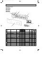
Rating Conditions (JIS B8616)
Service Ref.
Item
PCH-5GAK(H)
PCH-6GAK(H)
Cooling
Heating
Cooling
Heating
Btu/h
42,300
47,400 (57,700)
49,500
51,200 (61,400)
Capacity
W
12,400
13,900 (16,900)
14,500
15,000 (18,000)
kW
4.45
4.40 (7.40)
4.97
4.82 (7.82)
Total input
Service Ref.
PCH-5GAK(H)
PCH-6GAK(H)
Single phase. 50Hz. 220-240V
Power supply
kW
Input
0.24
0.24 (3.24)
0.24
0.24 (3.24)
A
Running current
1.06
1.06 (13.56)
1.06
1.06 (13.56)
A
Starting current
2.20
2.20 (14.70)
2.20
2.20 (14.70)
Munsell 0.70Y 8.59 / 0.97
External finish
Plate fin coil
Heat exchanger
Sirocco (direct) O 4
Fan(drive))No.
0.15
Fan motor output
kW
27 -34 <953-1,200>
Airflow(Low-High)
K/min <CFM>
0 (direct blow)
External static pressure
Pa(mmAq)
(3.0)
Booster heater
kW
Remote controller & built-in
Operation control & Thermostat
dB(A)
41-46
42-48
Noise level(Low-High)
mm,(in)
Cond. drain connection O.D.
26 (1)
mm,(in)
W
1,620 (63-3/4)
mm,(in)
Dimensions
D
680 (26-3/4)
mm,(in)
H
270 (10-5/8)
45 (99) [48 (106)]
43 (95) [46 (101)]
kg,(lbs)
Weight
PUH-6YKSA1.TH, PUH-6YKSA4.TH-A
PUH-5YKSA1.TH, PUH-5YKSA4.TH-A
Service Ref.
3 phases. 50Hz. 380-415V (4 wires)
Power supply
kW
Input
4.21
4.16
4.73
4.58
A
Running current
6.89
6.81
7.74
7.50
A
Starting current
53
53
74
74
External finish
Munsell 3.0Y 7.8/1.1
Refrigerant control
Capillary tube
Compressor
Hermetic
ZR61KC-TFD
ZR68KC-TFD
Model
3.5
4.0
kW
Motor output
Line start
Starter type
Anti-phase protector, Internal thermostat, Thermal switch, High-pressure switch
Protection devices
Heat exchanger
Plate fin coil
Fan(drive))No.
Propeller (direct) O 2
0.085 + 0.085
0.10 + 0.10
Fan motor output
kW
95 (3,350)
100 (3,530)
Airflow
K/min <CFM>
Defrost method
Reverse cycle
W
Crankcase heater
38
dB(A)
Noise level
55
56
mm,(in)
970 (38-3/16)
W
mm,(in)
345 + 24 (13-9/16 add 1)
D
Dimensions
mm,(in)
1,258 (49-1/2)
H
114 (251)
117 (258)
kg,(lbs)
Weight
R-22
Refrigerant
5.4 (11.9)
5.0 (11.0)
Charge
kg,(lbs)
9.52 (3/8)
Liquid
mm,(in)
Pipe size O.D.
19.05 (3/4)
Gas
mm,(in)
Indoor side
Flared
Connection method
Outdoor side
Flared
Height difference
Max. 50m
Between the indoor & outdoor unit
Piping length
Max. 50m
REFRIGERANT
PIPING
OUTDOOR UNIT
INDOOR UNIT
Function
Notes1. Rating Conditions (JIS B8616)
Cooling : Indoor : 27:(80oF)DB. 19:(66oF)WB
Outdoor : 35:(95oF)DB. 24:(75oF)WB
Heating : Indoor : 20:(68oF)DB.
Outdoor : 7:(45oF)DB. 6:(43oF)WB.
Refrigerant piping length (one way) : 5m(16ft)
2. Guaranteed operating range
Cooling
Heating
3. Above data based on indicated voltage
Indoor Unit 1 phase 240V 50Hz
Outdoor Unit 3 phase 415V 50Hz
11
Upper limit
Lower limit
Upper limit
Lower limit
Indoor
Outdoor
35: DB, 22.5: WB
46: DB
21: DB, 15.5: WB
-5: DB
27: DB
21: DB, 15.5: WB
20: DB
-8.5: DB, -9.5: WB
OC375A--1.qxp
07.1.22 2:15 PM
Page 12
Rating Conditions (SSA 385)
Service Ref.
Item
Function
Btu/h
W
kW
Capacity
Total input
Service Ref.
Power supply
Input
Running current
Starting current
External finish
Heat exchanger
Fan(drive))No.
Fan motor output
Airflow(Low-High)
External static pressure
Booster heater
Operation control & Thermostat
Noise level(Low-High)
Cond. drain connection O.D.
kW
A
A
REFRIGERANT
PIPING
Weight
Refrigerant
Charge
Cooling
45,700
13,400
7.28
W
D
H
dB(A)
mm,(in)
mm,(in)
mm,(in)
mm,(in)
kg,(lbs)
kW
A
A
kW
kW
K/min <CFM>
W
D
H
W
dB(A)
mm,(in)
mm,(in)
mm,(in)
kg,(lbs)
kg,(lbs)
Liquid
mm,(in)
Pipe size O.D.
Gas
mm,(in)
Indoor side
Connection method
Outdoor side
Height difference
Between the indoor & outdoor unit
Piping length
Heating
59,700
17,500
6.66
PCH-6GAK
Single phase. 60Hz. 220V
0.24
0.24
1.08
1.06
–
–
Munsell 0.70Y 8.59 / 0.97
Plate fin coil
Sirocco (direct) O 4
0.15
27 -34 <953-1,200>
0 (direct blow)
–
Remote controller & built-in
0.24
1.08
–
kW
K/min <CFM>
Pa(mmAq)
kW
Weight
Service Ref.
Power supply
Input
Running current
Starting current
External finish
Refrigerant control
Compressor
Model
Motor output
Starter type
Protection devices
Heat exchanger
Fan(drive))No.
Fan motor output
Airflow
Defrost method
Crankcase heater
Noise level
Dimensions
PCH-6GAK
Heating
56,300
16,500
6.00
PCH-5GAK
INDOOR UNIT
OUTDOOR UNIT
Dimensions
PCH-5GAK
Cooling
37,500
11,000
6.76
41-46
0.24
1.06
–
42-48
26 (1)
1,620 (63-3/4)
680 (26-3/4)
270 (10-5/8)
43 (95)
PUH-5TKSA1.TH
45 (99)
PUH-6TKSA1.TH
3 phases. 60Hz,220V
5.76
7.04
17.38
20.3
135
140
Munsell 3.0Y 7.8/1.1
Capillary tube
Hermetic
6.52
19.23
135
ZR61KC-TF5
3.5
6.42
18.51
140
ZR68KC-TF5
4.0
Line start
Anti-phase protector, Internal thermostat, Thermal switch, High-pressure switch
Plate fin coil
Propeller (direct) O 2
0.085 + 0.085
0.10 + 0.10
95 (3,350)
100 (3,530)
Reverse cycle
38
55
56
970 (38-3/16)
345 + 24 (13-9/16 add 1)
1,258 (49-1/2)
114 (251)
117 (258)
R-22
5.4 (11.9)
5.0 (11.0)
9.52 (3/8)
19.05 (3/4)
Flared
Flared
Max. 50m
Max. 50m
Notes: w 1. Rating conditions (SSA 385)
Cooling: Indoor : D.B. 29: W.B. 19:
Outdoor : D.B. 46:
Heating:Indoor : D.B. 21:
Outdoor : D.B. 7:(45˚F) W.B. 6:(43˚F)
Refrigerant piping length(one way):5m(16ft)
w2. Above data based on indicated voltage
Indoor Unit 1 phase 220V 60Hz
Outdoor Unit 3 phase 220V 60Hz
12
OC375A--1.qxp
4
07.1.22 2:15 PM
Page 13
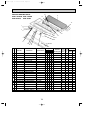
DATA
4-1. PERFORMANCE DATA
50Hz
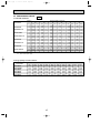
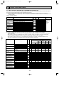
1) COOLING CAPACITY
Service Ref.
PCH-2GAK,
PCH-2GAKH/
PUH-2VKA1.TH
PCH-2GAK/
PUH-2AKA2.TH-A
PCH-2.5GAK,
PCH-2.5GAKH/
PUH-2.5VKA1.TH
PCH-2.5GAK/
PUH-2.5AKA2.TH-A
PCH-3GAKH/
PUH-3VKA1.TH,
PUH-3YKA1.TH
PCH-3GAK/
PUH-3VKA1.TH,
PUH-3VKA3.TH-A,
PUH-3YKA1.TH,
PUH-3YKA2.TH-A
PCH-4GAK,
PCH-4GAKH/
PUH-4YKSA.TH
PUH-4YKSA1.TH-A
PCH-5GAK,
PCH-5GAKH/
PUH-5YKSA1.TH
PUH-5YKSA4.TH-A
PCH-6GAK,
PCH-6GAKH/
PUH-6YKSA1.TH
PUH-6YKSA4.TH-A
Indoor
Intake
air
WB°C
16
18
20
22
16
18
20
22
16
18
20
22
16
18
20
22
16
18
20
22
16
18
20
22
16
18
20
22
16
18
20
22
16
18
20
22
20
CA
5448
5800
6157
6517
5347
5693
6043
6396
7062
7519
7981
8448
6860
7304
7753
8207
7566
8056
8551
9052
7667
8164
8665
9172
10088
10741
11402
12069
12510
13319
14138
14965
14628
15575
16532
17500
25
P.C.
1.84
1.88
1.92
1.95
1.83
1.86
1.90
1.93
2.08
2.12
2.16
2.20
2.03
2.07
2.11
2.15
2.63
2.68
2.73
2.78
2.63
2.68
2.73
2.78
2.69
2.75
2.80
2.85
3.57
3.64
3.71
3.78
3.98
4.06
4.14
4.22
CA
5299
5648
6012
6392
5200
5543
5901
6274
6869
7321
7794
8286
6672
7112
7571
8050
7359
7844
8350
8878
7457
7948
8462
8997
9812
10459
11134
11838
12167
12969
13806
14679
14228
15165
16144
17164
P.C.
1.92
1.96
2.00
2.04
1.91
1.94
1.98
2.02
2.16
2.21
2.25
2.30
2.11
2.16
2.20
2.24
2.74
2.80
2.85
2.91
2.74
2.80
2.85
2.91
2.81
2.87
2.92
2.98
3.72
3.79
3.87
3.95
4.15
4.24
4.32
4.41
Outdoor intake air DB°C
30
35
CA
P.C.
CA
P.C.
5104 2.07
4897 2.22
5442 2.12
5226 2.27
5798 2.16
5574 2.33
6171 2.21
5940 2.38
5009 2.05
4806 2.20
5341 2.10
5129 2.25
5690 2.14
5471 2.31
6057 2.19
5830 2.36
6616 2.33
6348 2.50
7054 2.38
6775 2.56
7515 2.44
7225 2.62
7999 2.49
7700 2.68
6427 2.28
6167 2.44
2.33
6853
6581 2.50
7301 2.38
7019 2.56
7771 2.43
7480 2.62
7089 2.95
6802 3.16
7558 3.02
7259 3.24
3.08
8052
7741 3.32
8571 3.15
8250 3.40
7184 2.95 6.892 3.16
7659 3.02
7358 3.24
8159 3.08
7845 3.32
3.15
8685
8360 3.40
9452 3.02
9069 3.24
10078 3.09
9678 3.32
10736 3.16 10322 3.40
11427 3.23 11000 3.48
11720 4.00 11245 4.29
12496 4.10 12001 4.40
13313 4.19 12799 4.50
14170 4.27 13640 4.61
13705 4.47 13150 4.79
14613 4.57 14033 4.91
15568 4.67 14967 5.03
16570 4.77 15951 5.15
40
CA
4678
5000
5341
5700
4592
4908
5242
5595
6064
6482
6923
7389
5891
6296
6726
7178
6515
6954
7419
7910
6585
7038
7517
8023
8686
9272
9892
10547
10771
11497
12266
13078
12595
13445
14344
15293
45
P.C.
2.37
2.43
2.49
2.56
2.35
2.41
2.47
2.54
2.67
2.73
2.81
2.89
2.60
2.67
2.74
2.82
3.38
3.46
3.55
3.65
3.38
3.46
3.55
3.65
3.46
3.55
3.64
3.74
4.58
4.70
4.82
4.96
5.12
5.25
5.39
5.54
CA
4447
4764
5099
5451
4365
4676
5004
5350
5765
6176
6609
7067
5600
5999
6421
6865
6199
6632
7089
7570
6259
6705
7176
7672
8266
8842
9451
10094
10249
10964
11720
12516
11985
12821
13705
14636
P.C.
2.52
2.58
2.66
2.75
2.50
2.56
2.64
2.73
2.84
2.91
3.00
3.10
2.77
2.84
2.93
3.02
3.59
3.68
3.79
3.92
3.59
3.68
3.79
3.92
3.68
3.77
3.89
4.01
4.87
5.00
5.15
5.32
5.44
5.58
5.75
5.94
Notes CA : Capacity (W)
P.C. : Power consumption (kW)
Cooling capacity correction factors
Service Ref.
PCH-2GAK(H)
PCH-2.5GAK(H)
PCH-3GAK(H)
PCH-4GAK(H)
PCH-5GAK(H)
PCH-6GAK(H)
5m
1.00
1.00
1.00
1.00
1.00
1.00
10m
0.992
0.989
0.981
0.989
0.981
0.975
15m
0.983
0.980
0.968
0.980
0.968
0.955
Refrigerant piping length (one way)
20m
25m
30m
35m
0.978
0.966
0.959
0.950
0.970
0.960
0.950
0.940
0.952
0.940
0.925
0.913
0.970
0.960
0.950
0.940
0.952
0.940
0.925
0.913
0.935
0.918
0.900
0.884
13
40m
0.945
0.930
0.900
0.930
0.900
0.869
45m
—
0.920
0.886
0.920
0.886
0.855
50m
—
0.910
0.874
0.910
0.874
0.840
OC375A--1.qxp
07.1.22 2:15 PM
Page 14
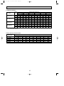
2) HEATING CAPACITY
Service Ref.
PCH-2GAK,
PCH-2GAKH/
PUH-2VKA1.TH
PCH-2GAK/
PUH-2AKA2.TH-A
PCH-2.5GAK,
PCH-2.5GAKH/
PUH-2.5VKA1.TH
PCH-2.5GAK/
PUH-2.5AKA2.TH-A
PCH-3GAK,
PCH-3GAKH/
PUH-3VKA1.TH,
PUH-3VKA3.TH-A,
PUH-3YKA1.TH,
PUH-3YKA2.TH-A
PCH-4GAK,
PCH-4GAKH/
PUH-4YKSA.TH
PUH-4YKSA1.TH-A
PCH-5GAK,
PCH-5GAKH/
PUH-5YKSA1.TH
PUH-5YKSA4.TH-A
PCH-6GAK,
PCH-6GAKH/
PUH-6YKSA1.TH
PUH-6YKSA4.TH-A
Indoor
Intake
-10
air
CA
P.C.
DB°C
15
4246 1.58
20
4066 1.71
25
3907 1.81
15
4280 1.56
20
4098 1.68
25
3939 1.79
15
4862 1.61
20
4656 1.73
25
4474 1.84
15
4862 1.59
20
4656 1.71
25
4474 1.82
15
5821 2.09
20
5574 2.26
25
5356 2.40
15
7156 2.29
20
6852 2.46
25
6585 2.61
15
9519 3.00
20
9115 3.23
25
8759 3.43
15
10272 3.29
20
9836 3.54
25
9453 3.76
-5
CA
4866
4675
4485
4905
4713
4521
5573
5354
5136
5573
5354
5136
6671
6409
6149
8202
7880
7560
10910
10481
10056
11773
11311
10851
P.C.
1.75
1.89
2.01
1.73
1.86
1.98
1.78
1.92
2.04
1.76
1.89
2.02
2.31
2.49
2.66
2.53
2.72
2.90
3.32
3.58
3.81
3.63
3.92
4.17
Outdoor intake air WB°C
0
5
CA
P.C.
CA
P.C.
5546 1.93
6285 2.11
5337 2.08
6051 2.28
5125 2.22
5827 2.44
5591 1.90
6336 2.09
5380 2.05
6100 2.25
5167 2.19
5874 2.41
6351 1.96
7198 2.15
6112 2.11
6929 2.32
5869 2.26
6673 2.48
6351 1.93
7198 2.12
6112 2.09
6929 2.29
5869 2.23
6673 2.45
7604 2.55
8617 2.80
7317 2.75
8296 3.01
7027 2.94
7989 3.23
9348 2.78 10594 3.05
8996 3.00 10199 3.29
8639 3.20
9821 3.52
12434 3.65 14091 4.01
11966 3.94 13566 4.32
11491 4.21 13064 4.63
13418 4.00 15206 4.39
12912 4.31 14640 4.73
12400 4.61 14098 5.07
10
CA
P.C.
7082 2.31
6816 2.49
6590 2.67
7139 2.28
6871 2.46
6643 2.64
8110 2.35
7806 2.53
7546 2.72
8110 2.32
7806 2.50
7546 2.68
9710 3.06
9345 3.30
9034 3.53
11937 3.34
11488 3.60
11107 3.86
15878 4.39
15281 4.72
14774 5.07
17135 4.81
16491 5.18
15943 5.55
15
CA
P.C.
7936 2.52
7632 2.71
7413 2.91
8000 2.49
7963 2.68
7473 2.87
9088 2.57
8740 2.76
8489 2.96
9088 2.53
8740 2.73
8489 2.92
10880 3.34
10463 3.59
10163 3.85
13376 3.64
12863 3.92
12495 4.21
17792 4.78
17110 5.15
16620 5.52
19200 5.24
18464 5.64
17935 6.05
Notes CA : Capacity (W)
P.C. : Power consumption (kW)
Heating capacity correction factors
Service Ref.
PCH-2GAK(H)
PCH-2.5GAK(H)
PCH-3GAK(H)
PCH-4GAK(H)
PCH-5GAK(H)
PCH-6GAK(H)
5m
1.00
1.00
1.00
1.00
1.00
1.00
10m
1.00
1.00
1.00
1.00
1.00
1.00
15m
1.00
1.00
1.00
1.00
1.00
1.00
Refrigerant piping length (one way)
20m
25m
30m
35m
1.00
1.00
1.00
0.998
1.00
1.00
1.00
0.998
1.00
1.00
1.00
0.998
1.00
1.00
1.00
0.998
1.00
1.00
1.00
0.998
1.00
1.00
1.00
0.998
14
40m
0.995
0.995
0.995
0.995
0.995
0.995
45m
—
0.993
0.993
0.993
0.993
0.993
50m
—
0.990
0.990
0.990
0.990
0.990
OC375A--1.qxp
07.1.22 2:15 PM
Page 15
4-2. PERFORMANCE DATA
60Hz
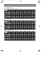
1) COOLING CAPACITY
Service Ref.
PCH-2GAK/
PUH-2NKA1.TH
PCH-2.5GAK/
PUH-2.5NKA1.TH
PCH-3GAK/
PUH-3NKA1.TH
PCH-4GAK/
PUH-4TKSA.TH
Indoor
Intake
air
W.B.(°C)
16
18
20
22
16
18
20
22
16
18
20
22
16
18
20
22
20
CA
5347
5693
6043
6396
7062
7519
7981
8448
7667
8164
8665
9172
11198
11923
12656
13396
25
P.C.
2.04
2.08
2.12
2.16
2.45
2.50
2.55
2.60
2.94
3.00
3.06
3.11
3.48
3.55
3.62
3.68
CA
5200
5543
5901
6274
6869
7321
7794
8286
7457
7949
8462
8997
10892
11609
12358
13140
P.C.
2.12
2.17
2.21
2.25
2.56
2.61
2.66
2.71
3.07
3.13
3.19
3.25
3.63
3.70
3.77
3.85
Outdoor intake air D.B.(°C)
30
35
CA
P.C.
CA
P.C.
5009 2.29
4806 2.45
5341 2.34
5129 2.51
5690 2.39
5471 2.57
6057 2.44
5830 2.63
2.75
6616
6348 2.95
7054 2.82
6775 3.02
7515 2.88
7225 3.10
7999 2.94
7700 3.17
7183 3.30
6892 3.54
3.38
7659
7355 3.63
8160 3.45
7845 3.71
8685 3.52
8360 3.80
10491 3.91 10066 4.19
11186 3.99 10743 4.29
11917 4.08 11457 4.39
12684 4.17 12210 4.50
40
CA
P.C.
4592 2.62
4908 2.68
5242 2.75
5595 2.83
6064 3.15
6482 3.23
6923 3.32
7389 3.41
6601 3.78
7047 3.87
7518 3.98
8016 4.09
9642 4.47
10292 4.58
10980 4.70
11707 4.84
45
CA
P.C.
4365 2.78
4676 2.85
5004 2.94
5350 3.04
5765 3.35
6176 3.44
6609 3.54
7067 3.66
6282 4.02
6720 4.12
7183 4.24
7671 4.38
9175 4.75
9815 4.87
10491 5.02
11204 5.18
Notes CA : Capacity (W)
P.C. : Power consumption (kW)
Cooling capacity correction factors
Service Ref.
PCH-2GAK
PCH-2.5GAK
PCH-3GAK
PCH-4GAK
PCH-5GAK
PCH-6GAK
5m
1.00
1.00
1.00
1.00
1.00
1.00
10m
0.992
0.989
0.981
0.989
0.981
0.975
15m
0.983
0.980
0.968
0.980
0.968
0.955
Refrigerant piping length (one way)
20m
25m
30m
35m
0.978
0.966
0.959
0.950
0.970
0.960
0.950
0.940
0.952
0.940
0.925
0.913
0.970
0.960
0.950
0.940
0.952
0.940
0.925
0.913
0.935
0.918
0.900
0.884
15
40m
0.945
0.930
0.900
0.930
0.900
0.869
45m
—
0.920
0.886
0.920
0.886
0.855
50m
—
0.910
0.874
0.910
0.874
0.840
OC375A--1.qxp
07.1.22 2:15 PM
Page 16
2) HEATING CAPACITY
Service Ref.
PCH-2GAK/
PUH-2NKA1.TH
PCH-2.5GAK/
PUH-2.5NKA1.TH
PCH-3GAK/
PUH-3NKA1.TH
PCH-4GAK/
PUH-4TKSA.TH
Indoor
Intake
air
D.B.(°C)
15
20
25
15
20
25
15
20
25
15
20
25
-10
P.C.
CA
4280 1.76
4098 1.90
3939 2.01
5479 2.01
5246 2.17
5041 2.30
6198 2.37
5934 2.56
5703 2.72
8457 2.84
8098 3.06
7783 3.25
-5
CA
4905
4713
4521
6279
6032
5787
7103
6824
6547
9693
9312
8934
P.C.
1.95
2.10
2.23
2.22
2.40
2.55
2.62
2.83
3.01
3.14
3.38
3.60
Outdoor intake air W.B.(°C)
0
5
CA
P.C.
CA
P.C.
5591 2.14
6336 2.35
5380 2.31
6100 2.53
5167 2.47
5874 2.71
7157 2.45
8110 2.69
6887 2.64
7808 2.90
6613 2.82
7519 3.10
8096 2.89
9175 3.17
7791 3.11
8833 3.42
7481 3.33
8506 3.66
11048 3.45 12520 3.79
10631 3.72 12053 4.09
10209 3.98 11607 4.37
10
CA
P.C.
7139 2.57
6871 2.77
6643 2.97
9138 2.94
8795 3.17
8503 3.40
10338 3.47
9949 3.74
9619 4.01
14107 4.15
13577 4.47
13126 4.79
15
CA
P.C.
8000 2.80
7693 3.02
7473 3.24
10240 3.21
9847 3.45
9565 3.70
11584 3.78
11140 4.07
10821 4.37
15808 4.52
15202 4.87
14766 5.22
Notes CA : Capacity (W)
P.C. : Power consumption (kW)
Heating capacity correction factors
Service Ref.
PCH-2GAK
PCH-2.5GAK
PCH-3GAK
PCH-4GAK
PCH-5GAK
PCH-6GAK
5m
1.00
1.00
1.00
1.00
1.00
1.00
10m
1.00
1.00
1.00
1.00
1.00
1.00
15m
1.00
1.00
1.00
1.00
1.00
1.00
Refrigerant piping length (one way)
20m
25m
30m
35m
1.00
1.00
1.00
0.998
1.00
1.00
1.00
0.998
1.00
1.00
1.00
0.998
1.00
1.00
1.00
0.998
1.00
1.00
1.00
0.998
1.00
1.00
1.00
0.998
16
40m
0.995
0.995
0.995
0.995
0.995
0.995
45m
—
0.993
0.993
0.993
0.993
0.993
50m
—
0.990
0.990
0.990
0.990
0.990
OC375A--1.qxp
07.1.22 2:15 PM
Page 17
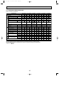
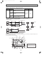
4-3. ELECTRICAL DATA
Rating Conditions (JIS B8616)
Indoor……220V 50Hz 1phase
Outdoor… 220V 50Hz 1phase / 380V 50Hz 3phase
MODEL
PCH-2GAKH
Indoor unit
Outdoor unit PUH-2VKA
PCH-5GAKH
PUH-5YKSA
PCH-6GAKH
PUH-6YKSA
Heating Cooling Heating Cooling Heating Cooling Heating Cooling Heating Cooling Heating
7,000
7,400
[10,160]
[4.03]
2.27
3.24
Indoor
Cooling
0.08
0.11
0.11
0.51
0.51
1.10
1.17
Outdoor
Mode
Capacity (W)
Total Input (kW)
Input (kW)
Current (A)
Starting current (A)
Input (kW)
Current (A)
Starting current (A)
PCH-2.5GAKH PCH-3GAKH PCH-4GAKH
PUH-2.5VKA PUH-3VKA/PUH-3YKA PUH-4YKSA
6,100
6,900
[8,760]
8,400
9,900
[12,620]
[3.40]
2.22
2.52
[4.79]
3.03
3.31
0.08
0.38
0.38
0.11
0.11
0.51
0.51
1.10
1.17
1.17
2.12
2.14
2.41
2.16
3.13
9.83
43
9.93
11.18
10.02
43
52
52
5,300
[7,280]
2.20
10,350
12,200
[16,220]
[5.57]
3.30
4.39
0.14
0.14
0.68
0.68
1.17
1.36
2.92
14.67/5.23 13.68/4.88
54 / 34
54 / 34
13,700
14,400
[17,320]
14,800
[6.85]
4.33
4.84
[7.28]
0.20
0.20
0.20
0.20
0.96
0.96
0.96
0.96
1.36
2.0
2.0
2.0
2.0
3.17
3.16
4.19
4.13
4.64
4.56
5.29
5.28
7.32
7.21
8.10
7.96
37
37
49
49
68
68
4.76
Indoor……230V 50Hz 1phase
Outdoor… 230V 50Hz 1phase / 400V 50Hz 3phase
MODEL
PCH-2GAKH
Indoor unit
Outdoor unit PUH-2VKA
PCH-4GAKH
PCH-5GAKH
PCH-6GAKH
PCH-3GAKH
PUH-2.5VKA PUH-3VKA/PUH-3YKA PUH-4YKSA
PUH-5YKSA
PUH-6YKSA
Cooling Heating Cooling Heating Cooling Heating Cooling Heating Cooling Heating Cooling Heating
6,150
[7,440]
2.25
2.27
[3.56]
6,950
7050
7,450
[8,980]
2.56
2.32
[4.25]
Indoor
5,350
0.09
0.09
0.12
0.41
0.41
1.15
1.15
Outdoor
Mode
Capacity (W)
Total Input (kW)
Input (kW)
Current (A)
Starting current (A)
Input (kW)
Current (A)
Starting current (A)
PCH-2.5GAKH
2.16
8,450
[10,380]
3.26
3.05
[4.98]
0.12
0.12
0.53
0.53
1.22
1.22
2.18
2.44
2.20
9.78
9.87
10.94
9.86
44
44
52
52
13,800
14,450
[17,660]
4.42
4.37
[7.13]
4.91
[7.55]
0.15
0.22
0.22
0.22
0.22
0.69
0.69
1.01
1.01
1.01
1.01
1.42
1.42
2.10
2.10
2.10
2.10
3.19
3.18
4.20
4.15
4.69
4.57
5.23
5.22
7.05
6.97
7.87
7.67
39
39
51
51
71
71
9,950
10,400
[12,880]
3.34
3.33
[5.81]
0.12
0.15
0.53
0.53
1.22
1.22
3.14
2.93
14.22 / 5.21 13.27 /4.86
56 / 36
56 / 36
12,300
[16,560]
14,900
4.79
Indoor……240V 50Hz 1phase
Outdoor… 240V 50Hz 1phase / 415V 50Hz 3phase
MODEL
PCH-2GAKH
Indoor unit
Outdoor unit PUH-2VKA
PCH-4GAKH
PCH-5GAKH
PCH-6GAKH
PCH-3GAKH
PUH-2.5VKA PUH-3VKA/PUH-3YKA PUH-4YKSA
PUH-5YKSA
PUH-6YKSA
Cooling Heating Cooling Heating Cooling Heating Cooling Heating Cooling Heating Cooling Heating
6,200
[7,600]
2.30
2.32
[3.72]
0.43
7,000
7,100
7,500
[9,200]
2.59
2.36
[4.46]
Indoor
5,400
0.10
0.10
0.13
0.43
0.55
1.20
1.20
Outdoor
Mode
Capacity (W)
Total Input (kW)
Input (kW)
Current (A)
Starting current (A)
Input (kW)
Current (A)
Starting current (A)
PCH-2.5GAKH
2.20
2.22
9.86
45
3.28
3.07
[5.17]
0.13
0.13
0.55
0.55
1.27
1.27
2.46
2.23
9.95
10.68
9.78
45
52
52
Indoor unit
Outdoor unit
Outdoor
Indoor
Mode
Capacity (W)
Total Input (kW)
Input (kW)
Current (A)
Starting current (A)
Input (kW)
Current (A)
Starting current (A)
17
10,450
14,500
[18,000]
4.45
4.40
[7.40]
4.97
[7.82]
0.16
0.24
0.24
0.24
0.24
0.70
1.06
1.06
1.06
1.06
1.48
1.48
2.20
2.20
2.20
2.20
3.20
3.19
4.21
4.16
4.73
4.58
5.24
5.22
6.89
6.81
7.74
7.50
40
40
53
53
74
74
[13,150]
3.36
[6.05]
0.13
0.16
0.55
0.70
1.27
1.27
3.15
2.94
58 / 37
PCH-2GAK
PCH-2.5GAK
PUH-2AKA
PUH-2.5AKA
Cooling Heating Cooling Heating
5,300 6,250 6,800 7,100
2.28
2.29
2.53
2.33
0.10
0.10
0.13
0.13
0.43
0.43
0.55
0.55
1.20
1.20
1.27
1.27
2.18
2.19
2.40
2.20
9.77
9.81 10.20 9.75
45
45
45
45
13,900
10,000
3.35
13.82 / 5.16 12.89 / 4.81
Indoor……240V 50Hz 1phase
Outdoor… 240V 50Hz 1phase
MODEL
8,500
[10,600]
58 / 37
12,400
[16,900]
15,000
4.82
OC375A--1.qxp
07.1.22 2:15 PM
Page 18
Rating Conditions (JIS B8616)
Indoor……220V 50Hz 1phase
Outdoor… 220V 50Hz 1phase / 380V 50Hz 3phase
MODEL
Indoor unit
Outdoor unit
PCH-2.5GAK
PCH-3GAK
PCH-4GAK
PUH-2.5VKA PUH-3VKA/PUH-3YKA PUH-4YKSA
PCH-5GAK
PUH-5YKSA
PCH-6GAK
PUH-6YKSA
5,300
6,100
6,900
7,000
7,500
8,400
9,900
10,350
12,200
13,700
14,400
14,800
2.20
2.22
2.52
2.27
3.24
3.03
3.31
3.30
4.39
4.33
4.84
4.76
Indoor
Cooling Heating Cooling Heating Cooling Heating Cooling Heating Cooling Heating Cooling Heating
0.08
0.08
0.11
0.11
0.11
0.11
0.14
0.14
0.20
0.20
0.20
0.20
0.38
0.38
0.51
0.51
0.51
0.51
0.68
0.68
0.96
0.96
0.96
0.96
1.10
1.10
1.17
1.17
1.17
1.17
1.36
1.36
2.0
2.0
2.0
2.0
Outdoor
Mode
Capacity (W)
Total Input (kW)
Input (kW)
Current (A)
Starting current (A)
Input (kW)
Current (A)
Starting current (A)
PCH-2GAK
PUH-2VKA
2.12
2.14
2.41
2.16
3.13
2.92
3.17
3.16
4.19
4.13
4.64
4.56
9.83
9.93
11.18
10.02
5.29
5.28
7.32
7.21
8.10
7.96
43
43
52
52
37
37
60
60
68
68
14.67/5.23 13.68/4.88
54 / 34
54 / 34
Indoor……230V 50Hz 1phase
Outdoor… 230V 50Hz 1phase / 400V 50Hz 3phase
MODEL
Indoor unit
Outdoor unit
PCH-2.5GAK
PCH-3GAK
PCH-4GAK
PUH-2.5VKA PUH-3VKA/PUH-3YKA PUH-4YKSA
PCH-5GAK
PUH-5YKSA
PCH-6GAK
PUH-6YKSA
5,350
6,150
6,950
7050
7,500
8,450
9,950
10,400
12,300
13,800
14,450
14,900
2.25
2.27
2.56
2.32
3.26
3.05
3.34
3.33
4.42
4.37
4.91
4.79
Indoor
Cooling Heating Cooling Heating Cooling Heating Cooling Heating Cooling Heating Cooling Heating
0.09
0.09
0.12
0.12
0.12
0.12
0.15
0.15
0.22
0.22
0.22
0.22
0.41
0.41
0.53
0.53
0.53
0.53
0.69
0.69
1.01
1.01
1.01
1.01
1.15
1.15
1.22
1.22
1.22
1.22
1.42
1.42
2.10
2.10
2.10
2.10
Outdoor
Mode
Capacity (W)
Total Input (kW)
Input (kW)
Current (A)
Starting current (A)
Input (kW)
Current (A)
Starting current (A)
PCH-2GAK
PUH-2VKA
2.16
2.18
2.44
2.20
3.14
2.93
3.19
3.18
4.20
4.15
4.69
4.57
9.78
9.87
10.94
9.86
5.23
5.22
7.05
6.97
7.87
7.67
44
44
52
52
39
39
63
63
71
71
14.22 / 5.21 13.27 /4.86
56 / 36
56 / 36
Indoor……240V 50Hz 1phase
Outdoor… 240V 50Hz 1phase / 415V 50Hz 3phase
MODEL
Indoor unit
Outdoor unit
PCH-2.5GAK
PCH-3GAK
PCH-4GAK
PUH-2.5VKA PUH-3VKA/PUH-3YKA PUH-4YKSA
PCH-5GAK
PUH-5YKSA
PCH-6GAK
PUH-6YKSA
5,400
6,200
7,000
7,100
7,600
8,500
10,000
10,450
12,400
13,900
14,500
15,000
2.30
2.32
2.59
2.36
3.28
3.07
3.36
3.35
4.45
4.40
4.97
4.82
Indoor
Cooling Heating Cooling Heating Cooling Heating Cooling Heating Cooling Heating Cooling Heating
0.10
0.10
0.13
0.13
0.13
0.13
0.16
0.16
0.24
0.24
0.24
0.24
0.43
0.43
0.55
0.55
0.55
0.55
0.70
0.70
1.06
1.06
1.06
1.06
1.20
1.20
1.27
1.27
1.27
1.27
1.48
1.48
2.20
2.20
2.20
2.20
Outdoor
Mode
Capacity (W)
Total Input (kW)
Input (kW)
Current (A)
Starting current (A)
Input (kW)
Current (A)
Starting current (A)
PCH-2GAK
PUH-2VKA
2.20
2.22
2.46
2.23
3.15
2.94
3.20
3.19
4.21
4.16
4.73
4.58
9.86
9.95
10.68
9.78
5.24
5.22
6.89
6.81
7.74
7.50
45
45
52
52
40
40
65
65
74
74
13.82 / 5.16 12.89 / 4.81
58 / 37
18
58 / 37
OC375A--1.qxp
07.1.22 2:15 PM
Page 19
Indoor ······220V 60Hz 1phase
Outdoor····220V 60Hz 1phase/3phases
Rating conditions (Cooling)…Indoor : D.B. 27: W.B. 19: Outdoor : D.B. 35:
MODEL
Indoor unit
Outdoor unit
Outdoor
unit
Indoor
unit
Mode
Capacity (W)
Total Input (kW)
Input (kW)
Current (A)
Starting current (A)
Input (kW)
Current (A)
Starting current (A)
PCH-2GAK
PUH-2NKA
Cooling
5,300
2.54
0.13
0.61
1.03
2.41
11.07
45
PCH-2.5GAK
PUH-2.5NKA
Cooling
7,000
3.06
0.15
0.70
1.11
2.91
13.50
58
Rating condition (Cooling)…Indoor : D.B. 29: W.B.19:
Rating condition (Heating)…Indoor : D.B. 21:
MODEL
Indoor unit
Outdoor unit
Outdoor Indoor
unit
unit
Mode
Capacity (W)
Total Input (kW)
Input (kW)
Current (A)
Input (kW)
Current (A)
Starting current (A)
PCH-2GAK
PUH-2NKA
Cooling
Heating
4,400
6,250
2.96
2.58
0.13
0.13
0.61
0.61
2.83
2.45
12.99
11.2
45
45
Outdoor : D.B. 46:
Outdoor : D.B. 7: W.B. 6:
}
(SSA385,386)
PCH-2.5GAK
PUH-2.5NKA
Cooling
Heating
6,000
8,000
3.58
2.95
0.15
0.15
0.70
0.70
3.43
2.80
15.75
13.0
58
58
Rating conditions (Cooling)…Indoor : D.B. 27: W.B. 19: Outdoor : D.B 35:
MODEL
Indoor unit
Outdoor unit
Outdoor
unit
Indoor
unit
Mode
Capacity (W)
Total Input (kW)
Input (kW)
Current (A)
Starting current (A)
Input (kW)
Current (A)
Starting current (A)
PCH-3GAK
PUH-3NKA
Cooling
7,600
3.67
0.15
0.70
1.11
3.52
16.49
80
PCH-4GAK
PUH-4TKSA
Cooling
11,100
4.34
0.20
0.95
1.27
4.14
11.81
69
Rating condition (Cooling)…Indoor : D.B. 29: W.B. 19:
Rating condition (Heating)…Indoor : D.B. 21:
MODEL
Indoor unit
Outdoor unit
Outdoor Indoor
unit
unit
Mode
Capacity (W)
Total Input (kW)
Input (kW)
Current (A)
Input (kW)
Current (A)
Starting current (A)
Outdoor : D.B. 46: W.B. 24:
Outdoor : D.B. 7: W.B. 6:
}
(SSA385,386)
PCH-3GAK
PCH-4GAK
PCH-5GAK
PCH-6GAK
PUH-3NKA
Cooling
Heating
6,600
9,050
4.28
3.48
0.15
0.15
0.70
0.70
4.13
3.33
18.77
15.6
80
80
PUH-4TKSA
Cooling
Heating
9,850
12,350
5.21
4.16
0.20
0.20
0.95
0.95
5.01
3.96
14.14
11.3
69
69
PUH-5TKSA
Cooling
Heating
11,000
16,500
6.76
6.00
0.24
0.24
1.08
1.08
6.52
5.76
19.23
17.38
135
135
PUH-6TKSA
Cooling
Heating
13,400
17,500
7.28
6.66
0.24
0.24
1.06
1.06
7.04
6.42
20.3
18.51
140
140
19
OC375A--1.qxp
07.1.22 2:15 PM
Page 20
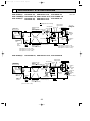
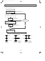
4-4. STANDARD OPERATION DATA
Rating Conditions (JIS B8616)
Total
V
A
Outdoor Indoor side Refrigerant circuit
side
W
KW
Electrical circuit
Service Ref.
Mode
Capacity
Input
Indoor unit Service Ref.
Phase, Hz
Volts
Amperes
Outdoor unit Service Ref.
Phase, Hz
Volts
Amperes
Discharge pressure
Suction pressure
Discharge temperature
Condensing temperature
Suction temperature
Ref. pipe length
Intake air temperature
Discharge air temperature
Intake air temperature
SHF
BF
V
A
Mpa·G(Of/F·G)
Mpa·G(Of/F·G)
°C
°C
°C
m
DB °C
WB °C
DB °C
DB °C
WB °C
PCH-2GAKH PCH-2.5GAKH PCH-3GAKH PCH-4GAKH PCH-5GAKH PCH-6GAKH
Cooling Heating Cooling Heating Cooling Heating Cooling Heating Cooling Heating Cooling Heating
6,200
7,100
8,500
10,450
15,000
5,400 [7,600]
7,000 [9,200]
7,500 [10,600]
10,000 [13,150]
12,400 13,900
[16,900] 14,500 [18,000]
2.32
2.36
3.07
3.35
4.40
4.82
2.30 [3.72] 2.59 [4.46] 3.28 [5.17] 3.36 [6.05] 4.45 [7.40] 4.97 [7.82]
PCH-2GAKH PCH-2.5GAKH PCH-3GAKH PCH-4GAKH PCH-5GAKH PCH-6GAKH
1, 50
1, 50
1, 50
1, 50
1, 50
1, 50
240
240
240
240
240
240
0.43 0.43 0.55 0.55 0.55 0.55 0.70 0.70 1.06 1.06 1.06 1.06
PUH-3VKA1.TH
PUH-2VKA1.TH PUH-2.5VKA1.TH
PUH-4YKSA.TH PUH-5YKSA1.TH PUH-6YKSA1.TH
PUH-3YKA1.TH
1, 50
1, 50
1/3, 50
3, 50
3, 50
3, 50
240
240
240 / 415
415
415
415
9.86 9.95 10.68 9.78 13.82/ 5.16 12.89/ 4.81 5.24 5.22 6.89 6.81 7.74 7.50
1.92
1.90
2.05
1.73
2.04
1.94
1.83
1.72
1.92
1.78
1.97
1.80
(19.6)
(19.4)
(20.9)
(17.6)
(20.8)
(19.8)
(18.7)
(17.5)
(19.6)
(18.1)
(20.1)
0.47
(4.8)
0.37
(3.77)
0.53
(5.4)
0.38
(3.87)
0.43
(4.39)
0.36
(3.67)
0.50
(5.1)
0.39
(3.98)
0.48
(4.90)
0.37
(3.77)
0.45
(4.59)
(3.88)
87
50
3.8
5
27
19
11.5
35
24
0.68
0.11
89
—
-2.7
5
20
15
44.8
7
6
—
—
85
53
6.9
5
27
19
12.4
35
24
0.69
0.14
77
—
-2.1
5
20
15
40.4
7
6
—
—
87
53
1.6
5
27
19
11.1
35
24
0.66
0.15
83
—
-2.9
5
20
15
44.8
7
6
—
—
78
48
6.7
5
27
19
11.1
35
24
0.68
0.12
75
—
-1.0
5
20
15
42.1
7
6
—
—
75
50
4.4
5
27
19
12.4
35
24
0.73
0.07
70
—
-2.8
5
20
15
42.4
7
6
—
—
74
51
2.6
5
27
19
10.0
35
24
0.65
0.14
69
—
-1.8
5
20
15
44.9
7
6
—
—
The unit of pressure has been changed to Mpa on the international system of unit (SI unit system).
The converted score against the traditional unit system can be gotten according to the formula below.
Of/F
F·G)
1(Mpa·G)=10.2(O
20
(18.4)
0.38
OC375A--1.qxp
07.1.22 2:15 PM
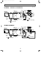
Page 21
Service Ref.
Outdoor Indoor side
side
Refrigerant circuit
Electrical circuit
Total
Mode
Capacity
Input
Indoor unit Service Ref.
Phase, Hz
Volts
Amperes
Outdoor unit Servise Ref.
Phase, Hz
Volts
Amperes
Discharge pressure
Suction pressure
Discharge temperature
Condensing temperature
Suction temperature
Ref. pipe length
D.B.
W.B.
Discharge air temperature D.B.
D.B.
Intake air temperature
W.B.
SHF
BF
Intake air temperature
PCH-4GAK
PCH-5GAK
PCH-6GAK
PCH-2.5GAK
PCH-3GAK
PCH-2GAK
Cooling Heating Cooling Heating Cooling Heating Cooling Heating Cooling Heating Cooling Heating
W
5,300 6,250 6,800 7,100 7,600 8,500 10,000 10,450 12,400 13,900 14,500 15,000
KW
4.97 4.82
3.07 3.36 3.35 4.45 4.40
2.28 2.29 2.53 2.33 3.28
PCH-4GAK
PCH-5GAK
PCH-6GAK
PCH-2.5GAK
PCH-3GAK
PCH-2GAK
1, 50
1, 50
1, 50
1, 50
1, 50
1, 50
V
240
240
240
240
240
240
A
1.06 1.06
0.55 0.70 0.70 1.06 1.06
0.43 0.43 0.55 0.55 0.55
PUH-3VKA3.TH-A
PUH-4YKSA1.TH-A PUH-5YKSA4.TH-A PUH-6YKSA4.TH-A
PUH-2AKA2.TH-A PUH-2.5AKA2.TH-A
PUH-3YKA2.TH-A
3, 50
3, 50
3, 50
1, 50
1, 50
1/3, 50
V
415
415
415
240
240
240 / 415
A
7.74 7.50
9.77 9.81 10.20 9.75 13.82/5.16 12.89/4.81 5.24 5.22 6.89 6.81
MPa
1.97 1.80
1.94 1.83 1.72 1.92 1.78
1.92 1.90 2.01 1.75 2.04
(kgf/F) (19.6) (19.4) (20.5) (17.9) (20.8) (19.8) (18.7) (17.5) (19.6) (18.1) (20.1) (18.4)
MPa
0.45 0.38
0.36 0.50 0.39 0.48 0.37
0.47 0.37 0.52 0.38 0.43
(kgf/F)
(5.8) (3.8) (5.3) (3.9) (4.4) (3.7) (5.1) (4.0) (4.9) (3.8) (4.6) (3.9)
78
75
74
75
70
69
°C
87
83
82
74
91
90
48
50
51
—
—
—
°C
53
—
50
—
50
—
6.7
4.4
2.6
-1.0
-2.8
-1.8
1.6
-2.9
6.8
-1.9
3.8
-2.8
°C
5
5
5
5
5
5
5
5
5
5
5
5
m
27
27
27
20
20
20
27
20
27
20
27
20
°C
19
19
19
15
15
15
19
15
19
15
19
15
°C
10.0 44.9
44.8 11.1 42.1 12.4 42.4
11.4 44.7 12.3 40.4 10.9
°C
35
35
35
7
7
7
35
7
35
7
35
7
°C
24
24
24
6
6
6
24
6
24
6
24
6
°C
0.68
0.73
0.65
—
—
—
0.67
—
0.69
—
0.68
—
0.12
0.07
0.14
—
—
—
0.15
—
0.14
—
0.11
—
The unit of pressure has been changed to MPa based on the international SI system.
F)
The conversion factor is : 1(MPa)=10.2(kgf/F
21
OC375A--1.qxp
07.1.22 2:15 PM
Page 22
PCH-2GAK
Service Ref.
Total
Mode
Capacity
Input
W
KW
Electrical circuit
Refrigerant circuit
Outdoor Indoor side
side
Discharge pressure
Suction pressure
Discharge temperature
Condensing temperature
Suction temperature
Ref. pipe length
D.B.
Intake air temperature
W.B.
Discharge air temperature D.B.
D.B.
Intake air temperature
W.B.
Outdoor Indoor side
side
Refrigerant circuit
Electrical circuit
Total
Service Ref.
Mode
Capacity
Input
Indoor unit service Ref.
Phase, Hz
Volts
Amperes
Outdoor unit service Ref.
Phase, Hz
Volts
Amperes
Heating
6,250
2.58
Cooling
6,000
3.58
Heating
8,000
2.95
PCH-3GAK
Cooling
6,600
4.28
Heating
9,050
3.48
PCH-4GAK
Cooling
9,850
5.21
Heating
12,350
4.16
PCH-2GAK
PCH-2.5GAK
PCH-3GAK
PCH-4GAK
V
A
1, 60
220
1, 60
220
1, 60
220
1, 60
220
V
A
MPa
(Of/F)
0.61
0.61
PUH-2NKA1.TH
1, 60
220
12.99
11.2
2.48
1.99
(2.53)
(20.3)
0.70
0.70
PUH-2.5NKA1.TH
1, 60
220
15.75
13.0
2.59
1.95
(26.4)
(19.9)
0.70
0.70
PUH-3NKA1.TH
1, 60
220
18.77
15.6
2.52
2.09
(25.7)
(21.3)
0.95
0.95
PUH-4TKSA.TH
3, 60
220
14.14
11.3
2.45
2.01
(25.0)
(20.5)
MPa
(Of/F)
0.49
(5.0)
0.36
(3.7)
0.52
(5.3)
0.37
(3.8)
0.42
(4.3)
0.35
(3.6)
0.47
(4.8)
0.36
(3.7)
:
:
:
m
:
:
:
:
:
94
70
6.7
5
29
19
14.0
46
24
97
–
-2.4
5
21
15
46.7
7
6
92
69
7.2
5
29
19
13.9
46
24
87
–
-2.5
5
21
15
44.3
7
6
93
70
2.2
5
29
19
13.6
46
24
94
–
-3.4
5
21
15
48.2
7
6
95
68
6.1
5
29
19
11.7
46
24
92
–
-2.2
5
21
15
48.1
7
6
Indoor unit service Ref.
Phase, Hz
Volts
Amperes
Outdoor unit service Ref.
Phase, Hz
Volts
Amperes
Cooling
4,400
2.96
PCH-2.5GAK
W
KW
V
A
V
A
MPa
Discharge pressure
(Of/F)
MPa
Suction pressure
(Of/F)
Discharge temperature
:
Condensing temperature
:
Suction temperature
:
Ref. pipe length
m
:
D.B.
Intake air temperature
:
W.B.
Discharge air temperature D.B.
:
:
D.B.
Intake air temperature
:
W.B.
PCH-5GAK
Cooling Heating
11,000
16,500
6.76
6.00
PCH-5GAK
1, 60
220
1.06
1.08
PUH-5TKSA1.TH
3, 60
220
19.23
17.38
1.92
2.23
(19.6)
(22.8)
PCH-6GAK
Cooling Heating
13,400
17,500
7.28
6.66
PCH-6GAK
1, 60
220
1.06
1.06
PUH-6TKSA1.TH
3, 60
220
20.3
18.51
1.97
2.37
(20.1)
(24.1)
0.38
(3.88)
0.33
(3.37)
0.36
(3.67)
0.33
(3.37)
78.2
50.8
0.6
5
29
19
12.9
46
24
94.3
–
-2.9
5
21
15
49.5
7
6
78.9
49.2
0.2
5
29
19
11.8
46
24
91.9
–
-2.1
5
21
15
50.3
7
6
The unit of pressure has been changed to MPa based on the international SI system.
F)
The conversion factor is : 1(MPa)=10.2(kgf/F
22
1
2
3
4
When electrical
box is pulled
down
6~7
2
23
928
7
Electrical box 70
525
Celling
8
226
86
2
138
171
263
352
5
1 4
46 175
131
Electrical box [Front view]
32
161
3
179
42
3879
38
Air intake
Air outlet
17
150
918
1000
904
983
933 (suspension bolt pitch)
140
6
70
80
15
85
(3/8F) liquid
(5/8F) gas
(Drainage)
182
201
241
NOTES:
1. Use M10 or W3/8 screws for anchor bolt.
2. Please be sure when installing the drain-up machine (option parts).
refrigerant pipe will be only upper drain pipe arrangement.
5 Refrigerant-pipe connection (liquid pipe side/flared connection)
6 Knock out hole for upper pipe arrangement
7 Knock out hole for left drain pipe arrangement
8 Knock out hole for wiring arrangement
81 76
Drainage pipe connection (26mm I.D.)
Drainage pipe connection (for the left arrangement)
Knock out hole for left drain-piping arrangement
Refrigerant-pipe connection (gas pipe side/flared connection)
PCH-2GAK
PCH-2GAKH
254
320
180
210
07.1.22 2:15 PM
680
5
157
OC375A--1.qxp
Page 23
OUTLINES AND DIMENSIONS
Unit : mm
24
When electrical
box is pulled
down
2
1235
7
Electrical box
525
Celling
70
8
226
2
86
138
171
263
416
5
1 4
Air outlet
Air intake
131
[ Front view ]
46 175 1
Electrical box
32
161
3
179
42
3879
38
1228
1310
1214
1290
1240 (suspension bolt pitch)
150
6~7
140
70
6
15
85
(3/8F liquid)
(5/8F gas)
(Drainage)
182
201
241
NOTES:
1. Use M10 or W3/8 screws for anchor bolt.
2. Please be sure when installing the drain-up machine (option parts).
refrigerant pipe will be only upper drain pipe arrangement.
80
320
180
17
5 Refrigerant-pipe connection (liquid pipe side/flared connection)
6 Knock out hole for upper pipe arrangement
7 Knock out hole for left drain pipe arrangement
8 Knock out hole for wiring arrangement
210
Drainage pipe connection (26mm I.D.)
Drainage pipe connection (for the left arrangement)
Knock out hole for left drain-piping arrangement
Refrigerant-pipe connection (gas pipe side/flared connection)
81 76
254
07.1.22 2:15 PM
680
1
2
3
4
157
OC375A--1.qxp
Page 24
PCH-2.5GAK PCH-2.5GAKH
PCH-3GAK PCH-3GAKH
Unit : mm
25
3
239
2
When electrical
box is pulled
down
42
93
7
Electrical box
525
160
70
229
1235
Celling
[ Front view ]
8
2
687
86
138
171
263
5
192
4
Air intake
Air outlet
1
1228
1310
1214
1240 (suspension bolt pitch)
150
Electrical box
38 140
38
1
236
45
17
6~7
140
70
6
16
87
(3/8F liquid)
(3/4F-gas)
(Drainage)
182
198
245
5 Refrigerant-pipe connection (liquid pipe side/flared connection)
6 Knock out hole for upper pipe arrangement
7 Knock out hole for left drain pipe arrangement
NOTES:
8 Knock out hole for wiring arrangement
1. Use M10 or W3/8 screws for anchor bolt.
2. Please be sure when installing the drain-up machine (option parts).
refrigerant pipe will be only upper drain pipe arrangement.
217
Drainage pipe connection (26mm I.D.)
Drainage pipe connection (for the left arrangement)
Knock out hole for left drain-piping arrangement
Refrigerant-pipe connection (gas pipe side/flared connection)
81 96
80
320
207
680
07.1.22 2:15 PM
254
1
2
3
4
270
OC375A--1.qxp
Page 25
PCH-4GAK
PCH-4GAKH
Unit : mm
239
42
When electrical
box is pulled
down
Electrical box
93
6~7
7
Electrical box
525
160
229
1545
70
Celling
[ Front view ]
2
8
38 140
38
86
138
171
263
687
5
1
4
1
236
26
Air intake
Air outlet
45
1535
1620
1524
1547(suspension bolt pitch)
18
140
70
6
16
87
(3/8F liquid)
(3/4F gas)
(Drainage)
182
198
245
NOTES:
1. Use M10 or W3/8 screws for anchor bolt.
2. Please be sure when installing the drain-up machine (option parts).
refrigerant pipe will be only upper drain pipe arrangement.
80
320
207
3
2
192
5 Refrigerant-pipe connection (liquid pipe side/flared connection)
6 Knock out hole for upper pipe arrangement
7 Knock out hole for left drain pipe arrangement
8 Knock out hole for wiring arrangement
81 96
150
Drainage pipe connection (26mm I.D.)
Drainage pipe connection (for the left arrangement)
Knock out hole for left drain-piping arrangement
Refrigerant-pipe connection (gas pipe side/flared connection)
PCH-5GAKH
PCH-6GAKH
680
07.1.22 2:15 PM
254
1
2
3
4
217
PCH-5GAK
PCH-6GAK
270
OC375A--1.qxp
Page 26
Unit : mm
OC375A--1.qxp
07.1.22 2:15 PM
Page 27
Unit : mm
WIRED REMOTE CONTROLLER
120
130
19
27
OC375A--1.qxp
6
07.1.22 2:15 PM
Page 28
WIRING DIAGRAM
PCH-2GAK(H) PCH-2.5GAK(H) PCH-3GAK(H)
PCH-4GAK(H) PCH-5GAK(H)
PCH-6GAK(H)
NAME
INDOOR POWER BOARD
INDOOR CONTROLLER BOARD
FUSE (T6.3AL250V)
VARISTOR
CONNECTOR<LOSSNAY>
CONNECTOR<REMOTE SWITCH>
CONNECTOR<HA TERMINAL-A>
CONNECTOR<CENTRALLY CONTROL>
SWITCH <MODEL SELECTION>*See Table 1.
SWITCH <CAPACITY CODE>*See Table 2.
SWITCH<SYSTEM SELECTION>*See Table 3.
SWITCH<EMERGENCY OPERATION>
CONNECTOR<EMERGENCY OPERATION>
RELAY<DRAIN PUMP>
RELAY<FAN MOTOR>
FAN CONTROL ELEMENT
POWER SUPPLY<I.B>
POWER SUPPLY<R.B>
SYMBOL
C
MF
MV
DP
TB2
TB4
NAME
CAPACITOR<FAN MOTOR>
FAN MOTOR
VANE MOTOR
DRAIN-UP MACHINE (OPTIONAL)
TERMINAL BLOCK (POWER SUPPLY)
TERMINAL BLOCK<INDOOR/OUTDOOR
CONNECTING LINE>
TERMINAL BLOCK<REMOTE CONTROLLER
TRANSMISSION LINE >
ROOM TEMP.THERMISTOR
<0:/15k", 25:/5.4k" DETECT>
PIPE TEMP.THERMISTOR/LIQUID
<0:/15k", 25:/5.4k" DETECT>
TB5
TH1
TH2
SYMBOL
W.B
RU
BZ
LED1
LED2
SW1
SW2
R.B
TB6
HEATER
FS1,2 THERMAL FUSE
<98: 10A: 2GAKH/ 117: 16A: 4GAKH/ 110: 16A: 2.5, 3, 5,6GAKH>
HEATER
H1
26H HEATER THERMAL SWITCH
88H HEATER CONTACTOR
TB2
Please set the voltage
using the remote controller.
For the setting method,
please refer to the indoor
unit Installation Manual
TB4
When installing drain-up
machine (Optional part).
WHT
(D.SENSOR)
CN31
1 2 3
X1
ON
OFF
SW5
WHT
RED
(D.SENSOR) (PUMP)
CN27
CN31
1 2 3
GRN
(VANE)
CN6V
SW6
1 2
WHT
(WIRERESS)
CN90
CN41
CN2L
YLW
(HEATER)
CN24
GRY
88H
BLK
WHT
6
RED
1
FS1
FS2
RED
WHT
1 2
TH2
1
2
RED 5
88H
TB2
3 RED
BLU
L
N
POWER SUPPLY
~(1PHASE)
220-240V 50Hz
220V 60Hz
GRN/YLW
9
W.B
(OPTION)
R.B
TB6
2 1
TB5
TH1
26H
RED
6
5
H1
LED1
1 2
6
MV
CN2S
1 2 (WHT)
LED2
1 2
*When installing optional
drain-up machine, disconnect
the CN31 jumper connector
and replace it with the
drain sensor (DS).
1 2
CN51 CN32
BLK
(INDOOR/OUTDOOR
RED
COMUNICATION)
(INTAKE)
WHT
BLU
CN30
CN20
(PIPE)
(REMOCON)
1 2 CN21 1 2 3 CN22
YLW
ORN
BRN
ON
OFF
SWE
SW2
BOARD)
CNDK
WHT
(POWER 1
BOARD) 2
CN2D
ZNR
X4
SW1
CND
BLU
BLU
X4
FUSE
I.B
YLW
RED
BLU
RED
WHT WHT
BLK
CNP
X1
BCR
TO OUTDOOR UNIT
PCH-2~6GAKH models only
I.B
ORN
RED
1 3 (POWER)
1 3 (POWER
BLU
1 3 (D.U.M)
RED
(D.HEATER) 1 3
CNC
DC13.1V
RED
WHT
1 3 5
1
2
3
[Servicing]
Fasten terminal of the terminal board"TB4"equips lock system.
To remove the fastened terminal, pull it while pressing the
protruding portion (locking lever) of the terminal.
The fastened terminal protruding portion should face upward.
1 2 3 CNSK
(RED)
DP
FAN
POWER SUPPLY
~(1PHASE)
220-240V 50Hz
220V 60Hz
P.B
(OPTION)
WHT
1 3 5 (FAN)
L
N
GRN/YLW
MF
Refer to tables 1, 2, 3
NAME
WIRELESS REMOTE CONTROLLER BOARD<OPTION>
RECEIVING UNIT
BUZZER
LED<RUN INDICATOR >
LED<HOT ADJUST>
SWITCH<HEATING ON/OFF>
SWITCH<COOLING ON/OFF>
WIRED REMOTE CONTROLLER BOARD
TERMINAL BLOCK<REMOTE CONTROLLER
TRANSMISSION LINE >
YLW
SYMBOL
P.B
I.B
FUSE
ZNR
CN2L
CN32
CN41
CN51
SW1
SW2
SW5
SW6
SWE
X1
X4
BCR
LED1
LED2
1
2 TRANSMISSION WIRES DC12V
CNB
BZ
RU
RECEIVER
LED1 LED2 SW2 SW1
DS
Table 1
SW1
[Self-diagnosis]
1. For details on how to operate self-diagnosis with the wireless
remote control, refer to the technical manuals etc.
2. For the wired remote control : When you quickly press twice the
CHECK switch on the remote control, the unit begins self-diagnosis,
and Check Codes generated in the past appear on the display.
For Check Codes and Symptoms refer to the table.
Check code
P1
P2
P4
P5
P6
P8
E0–E5
Fb
––––
FFFF
1 2 3 4 5
SW5
1 2 3 4 5 6 7 8
ON
OFF
ON
OFF
Table 2
MODELS
Symptom
Abnormality of room temperature thermistor.(TH1).
Abnormality of pipe temperature thermistor / Liquid.(TH2).
Abnormality of drain sensor(DS).
Malfunction of drain-up machine.
Freezing / overheating protection is working.
Abnormality in outdoor unit. Refer to outdoor unit wiring diagram.
Abnormality of the signal transmission between remote
controller and indoor unit.
Abnormality of indoor controller board.
No trouble generated in the past.
No corresponding unit.
NOTES:
1. Since the outdoor side electric wiring may change, be sure to
check the outdoor unit electric wiring for servicing.
2. Indoor and outdoor connecting wires are made with polarities, make
wiring matching terminal numbers (1, 2, 3).
3. Symbols used in wiring diagram above are,
: Connector,
: Terminal (block).
Table 3
PCH-2GAK(H)
PCH-2.5GAK(H)
PCH-3GAK(H)
SW2
1 2 3 4 5
1 2 3 4 5
1 2 3 4 5
MODELS
ON
OFF
PCH-4GAK(H)
ON
OFF
PCH-5GAK(H)
ON
OFF
PCH-6GAK(H)
SW2
1 2 3 4 5
1 2 3 4 5
1 2 3 4 5
[Emergency operation procedure]
1.When the indoor unit microcomputer has failed, but all other
components work properly, if you set the switch(SWE,SW6)on the indoor control
board, the indoor unit will begin Emergency Operation.
2.When you activate emergency operation of the cooling or heating, you have
to set the switch(SWE)and switch(SW6)on indoor controller.
SWE:ON
· Indoor fan is running high speed.
· Drain-up machine(optional)is working.
SW6-1:ON
· Emergency operation of cooling mode.
SW6-1,2:ON · Emergency operation of heating mode.
3.Before you activate emergency operation, check the following points:
Emergency operation cannot be activated when:
· The outdoor unit malfunctions. · The indoor fan malfunctions.
Emergency operation becomes continuous only by switching the
power source on / off. ON / OFF on the remote control or temperature control
etc. does not function.
Avoid operating for a long time when the outdoor unit begins defrosting
while emergency operation of the heating is activated, because it will start to blow cold air.
Emergency cooling should be limited to 10 hours maximum
(The indoor unit heat exchanger may freeze).
After emergency operation has been deactivated, set the switches etc. to their original positions.
Movement of the vanes does not work in emergency operation, therefore
you have to slowly set them manually to the appropriate position.
28
ON
OFF
ON
OFF
ON
OFF
OC375A--1.qxp
07.1.22 2:15 PM
7
Page 29
REFRIGERANT SYSTEM DIAGRAM
PCH-2GAK(H) / PUH-2VKA1.TH, PUH-2AKA2.TH-A, PUH-2NKA1.TH
PCH-2.5GAK(H) / PUH-2.5VKA1.TH, PUH-2.5AKA2.TH-A, PUH-2.5NKA1.TH
PCH-3GAK(H) / PUH-3VKA1.TH, PUH-3VKA3.TH-A, PUH-3NKA1.TH
PUH-3YKA1.TH, PUH-3YKA2.TH-A
Refrigerant flow in cooling
Refrigerant flow in heating
High pressure
control switch
Oil separator
Refrigerant pipe
(option)
4-way valve
15.88mm( 5/8")
Ball valve
(with heat insulator)
Strainer
Indoor unit
Service
port
Outdoor
coil
thermistor
(RT)
Service
port
Flared
connection
Strainer
Bypass
valve
Restrictor
valve
Accumulator
Indoor coil
thermistor
TH2
Restrictor
valve
Strainer
Refrigerant pipe Ball valve
(option)
(with service port)
9.52mm( 3/8")
(with heat insulator)
PUH-2(O.D.4.0 ✕ I.D.2.0-R430)
PUH-2.5(O.D.4.0 ✕ I.D.2.4-R1550)
PUH-3(O.D.4.0 ✕ I.D.2.4-R1070)
Capillary
tube
PCH-2(O.D.3.2 ✕ I.D.1.6-R230)
PCH-2.5(O.D.3.2 ✕ I.D.1.8-R430)
PCH-3(O.D.4.0 ✕ I.D.2.0-R280)
PUH-4YKSA.TH, PUH-4YKSA1.TH-A, PUH-4TKSA.TH
Oil separator
Refrigerant pipe
(option)
4-way valve
19.05mm( 3/4)
Ball valve
(with heat insulator) Strainer
Indoor unit
High pressure
control switch
Service
port
Outdoor unit
Outdoor heat exchanger
Outdoor
coil
thermistor
(RT)
Flexible tube
Indoor
heat
exchanger
Service
port
Strainer
Indoor coil
thermistor
TH2
Capillary
tube
Compressor
Distributor
with
strainer
PCH-4GAK(H) /
<R.V.coil>
Heating ON
Cooling OFF
Outdoor unit
Outdoor heat exchanger
Flexible tube
Indoor
heat
exchanger
Unit : mm
Restrictor
valve
Flared
connection
Bypass
valve
Restrictor
valve
Distributor
with
strainer
Capillary
tube
Accumulator
Ball valve
Refrigerant pipe
(option)
(with service port)
9.52mm( 3/8")
(with heat insulator)
(O.D.4.0 ✕ I.D.2.0-R350)
29
Capillary
tube
(O.D.3.2✕ I.D.2.0-R820)✕ 2
Compressor
Strainer
OC375A--1.qxp
07.1.22 2:15 PM
PCH-5GAK(H) /
PCH-6GAK(H) /
Page 30
Unit : mm
PUH-5YKSA1.TH, PUH-5YKSA4.TH-A
PUH-6YKSA1.TH, PUH-6YKSA4.TH-A
Oil
separator
Refrigerant pipe
(option)
4-way valve
19.05mm( 3/4")
Ball valve
(with heat insulator) Strainer
Indoor unit
Outdoor unit
Outdoor heat exchanger
High pressure
control switch
Service
port
Outdoor
coil
thermistor
(RT)
Flexible tube
Indoor
heat
exchanger
Service
port
Flared
connection
Strainer
Indoor coil
thermistor
TH2
Restrictor valve
Distributor
with
strainer
Capillary
tube
PCH-5
PCH-6
Restrictor
valve
Bypass
valve
Accumulator
Ball valve
Refrigerant pipe
(with service port)
(option)
9.52mm( 3/8")
(with heat insulator)
Compressor
Capillary
tube
Capillary tube
Strainer
PUH-5
Thermal switch PUH-6
(O.D.4.0 ✕ I.D.2.4-R840)✕ 2
(O.D.4.0 ✕ I.D.2.4-R1200)✕ 2
O.D.4.0 ✕ I.D.2.4-R270
O.D.4.0 ✕ I.D.3.0-R300
PCH-5GAK / PUH-5TKSA1.TH
PCH-6GAK / PUH-6TKSA1.TH
Oil
separator
Refrigerant pipe
(option)
4-way valve
19.05mm( 3/4")
Ball valve
(with heat insulator) Strainer
Indoor unit
PCH-5
PCH-6
Service
port
Outdoor
coil
thermistor
(RT)
Service
port
Strainer
Distributor
with
strainer
Outdoor unit
Outdoor heat exchanger
Flexible tube
Indoor
heat
exchanger
Indoor coil
thermistor
TH2
High pressure
control switch
Restrictor valve
Flared
connection
Restrictor
valve
Capillary
tube
Bypass
valve
Accumulator
Ball valve
Refrigerant pipe
(with service port)
(option)
9.52mm( 3/8")
Capillary tube
O.D.4.0 5 I.D.2.4-L270 (with heat insulator)
O.D.4.0 5 I.D.3.0-L300
30
Compressor
Capillary tube
Strainer
PUH-5
Thermal switch PUH-6
(O.D.4.0 o I.D.2.4-L840) o 2
(O.D.4.0 o I.D.2.4-L740) o 2
DPR
OC375A--2.qxp
07.1.22 2:14 PM
8
Page 31
TROUBLESHOOTING
8-1. TROUBLESHOOTING
<Error code display by self-diagnosis and actions to be taken for service (summary)>
Present and past error codes are logged and displayed on the wired remote controller or controller board of outdoor unit.
Actions to be taken for service,which depends on whether or not the the inferior phenomenon is reoccurring at service, are
summarized in the table below. Check the contents below before investigating details.
Unit conditions at service
Error code
Actions to be taken for service (summary)
Displayed
Judge what is wrong and take a corrective action
according to “SELF-DIAGNOSIS ACTION TABLE” (8-3).
Not displayed
Identify the cause of the inferior phenomenon and take
a corrective action according to “TROUBLESHOOTING
BY INFERIOR PHENOMENA ” (8-4).
The inferior phenomenon is
reoccurring.
1Consider the temporary defects such as the work of
protection devices in the refrigerant circuit including
compressor, poor connection of wiring, noise and etc.
Re-check the symptom, and check the installation
environment, refrigerant amount, weather when the
inferior phenomenon occurred, and wiring related.
2Reset error code logs and restart the unit after finishing
service.
3There is no abnormality in electrical components,
controller boards, and remote controller.
Logged
The inferior phenomenon is
not reoccurring.
1Recheck the abnormal symptom.
2Identify the cause of the inferior phenomenon and take
a corrective action according to “TROUBLESHOOTING
BY INFERIOR PHENOMENA ” (8-4).
3Continue to operate unit for the time being if the cause
is not ascertained.
4There is no abnormality in electrical components,
controller boards, remote controller etc.
Not logged
8-2. MALFUNCTION-DIAGNOSIS METHOD BY REMOTE CONTROLLER
<In case of trouble during operation>
When a malfunction occurs to air conditioner, both indoor unit and outdoor unit will stop and operation lamp blinks to inform
unusual stop.
■ Wired remote controller
1 Turn on the power.
2 Press the [CHECK] button twice.
3 Set address with [TEMP] button if system control is used.
4 Press the [ON/OFF] button to stop the self-check.
B
E D
A CHECK button
B Address
C TEMP. button
D IC : Indoor unit
OC: Outdoor unit
– – – – : No trouble generated in the past.
E Check code
F F F F : No corresponding unit.
F Unit No.
ERROR CODE
ERROR CODE
TEMP.
C
MENU
BACK
MONITOR/SET
ON/OFF
ON/OFF
E
B
FILTER
DAY
CHECK TEST
ERROR CODE
PAR-21MAA
OPERATION
CLOCK
G Timer ON/OFF button
CLEAR
F
G
A
<To delete check code>
1 Display the error code at the self-check result display screen.
2 The address for self-check will blink when the G
ON/OFF
button is pressed twice within three seconds.
31
OC375A--2.qxp
07.1.22 2:14 PM
Page 32
Wired remote controller
Symptom
1 Check code
P1
P2
P4
P5
PA
P6
P8
E4, E5
Intake sensor error
Pipe (TH2) sensor error
Drain sensor error
Drain pump error
Forced compressor stop
Freezing/ Overheating protection operation
Pipe temperature error / Outdoor unit error
Remote controller signal receiving error
–
–
Remark
–
–
Fb
E0, E3
E1, E2
Indoor unit control system error (memory error, etc.)
Remote controller transmission error
Remote controller control board error
• On wired remote controller
1Check code displayed in the LCD.
• If the unit cannot be operated properly after the above test run has been performed, refer to the following table to remove the cause.
Symptom
Cause
Wired remote controller
•For about 2 minutes after power-on,opFor about 2
PLEASE WAIT
minutes after
eration of the remote controller is not possible
power-on
due to system start-up. (Correct operation)
•Connector for the outdoor unit’s protection
device is not connected.
PLEASE WAIT → Error code
•Reverse or open phase wiring for the outdoor
After about 2
unit’s power terminal block
minutes has
expired after
Display messages do not
•Incorrect wiring between indoor and outdoor
power-on
appear even when operation
units
switch is turned ON (operation
•Remote controller wire short
lamp does not light up).
On the wireless remote controller with condition above, following phenomena take place.
• No signals from the remote controller are accepted.
• Operation lamp is blinking.
• The buzzer makes a short piping sound.
Note:
Operation is not possible for about 30 seconds after cancellation of function selection. (Correct operation)
For description of each LED (LED1, 2) provided on the indoor controller, refer to the following table.
LED1 (power for microcomputer)
LED2 (power for wired remote controller)
Indicates whether control power is supplied. Make sure that this LED is
always lit.
Indicates whether power is supplied to the wired remote controller.
This LED lights only in the case of the main indoor unit.
32
OC375A--2.qxp
07.1.22 2:14 PM
Page 33
Note: Refer to the manual of outdoor unit for the details of display
such as F, U, and other E.
8-3. SELF-DIAGNOSIS ACTION TABLE
Error Code Meaning of error code and detection method
Abnormality of room temperature
thermistor (TH1)
1 The unit is in 3-minute resume
prevention mode if short/open of
thermistor is detected. Abnormal if the
unit does not reset normally after 3 minutes. (The unit returns to normal operation, if it has normally reset.)
2 Constantly detected during cooling,
drying, and heating operation.
Short: 90: or more
P1
Open: -40: or less
Cause
1 Defective thermistor
characteristics
2 Contact failure of connector
(CN20) on the indoor controller
board (Insert failure)
3 Breaking of wire or contact
failure of thermistor wiring
4 Defective indoor controller
board
Countermeasure
1–3 Check resistance value of thermistor.
0: ······15.0k"
10: ····9.6k"
20: ····6.3k"
30: ····4.3k"
40: ····3.0k"
If you put force on (draw or bend) the lead wire
with measuring resistance value of thermistor
breaking of wire or contact failure can be
detected.
2 Check contact failure of connector (CN20) on
the indoor controller board. Refer to 8-7.
Turn the power back on and check restart
after inserting connector again.
4 Check room temperature display on remote
controller.
Replace indoor controller board if there is
abnormal difference with actual room
temperature.
Turn the power off, and on again to operate
after check.
P2
Abnormality of pipe temperature
thermistor/Liquid (TH2)
1 The unit is in 3-minute resume
prevention mode if short/open of
thermistor is detected. Abnormal if the
unit does not reset normally after 3 minutes. (The unit returns to normal operation, if it has normally reset.)
2 Constantly detected during cooling,
drying, and heating (except defrosting)
operation.
Short: 90: or more
Open: -40: or less
1 Defective thermistor
characteristics
2 Contact failure of connector
(CN21) on the indoor controller
board (Insert failure)
3 Breaking of wire or contact
failure of thermistor wiring
4 Defective refrigerant circuit is
causing thermistor temperature
of 90: or more or -40: or
less.
5 Defective indoor controller board
1–3 Check resistance value of thermistor.
For characteristics, refer to (P1) above.
2 Check contact failure of connector (CN21) on
the indoor controller board. Refer to 8-7. Turn
the power on and check restart after inserting
connector again.
4 Check pipe <liquid> temperature with remote
controller in test run mode. If pipe <liquid>
temperature is exclusively low (in cooling
mode) or high (in heating mode), refrigerant
circuit may have defective.
5 Check pipe <liquid> temperature with remote
controller in test run mode. If there is exclusive
difference with actual pipe <liquid> temperature,
replace indoor controller board.
Turn the power off, and on again to operate
after check.
P4
P5
Abnormality of drain sensor (DS)
1 Suspensive abnormality, if short/open of
thermistor is detected for 30 seconds
continuously.
Turn off compressor and indoor fan.
2 Short/open is detected for 30 seconds
continuously during suspensive
abnormality.
(The unit returns to normal operation,
if it has normally reset.)
3 Detect the following condition.
• During cooling and drying operation.
• In case that pipe <liquid> temperature
- room temperature <-10deg
(Except defrosting)
• When pipe <liquid> temperature or
room temperature is short/open
temperature.
• During drain pump operation.
1 Defective thermistor
characteristics
2 Contact failure of connector
(CN31) on the indoor controller
board. (Insert failure)
3 Breaking of wire or contact
failure of drain sensor wiring
4 Defective indoor controller board
Malfunction of drain pump (DP)
1 Suspensive abnormality, if thermistor
of drain sensor is let heat itself and
temperature rises slightly. Turn off
compressor and indoor fan.
2 Drain pump is abnormal if the condition
above is detected during suspensive
abnormality.
3 Constantly detected during drain pump
operation.
1 Malfunction of drain pump
2 Defective drain
Clogged drain pump
Clogged drain pipe
3 Attached drop of water at the
drain sensor
• Drops of drain trickles from
lead wire.
• Clogged filter is causing
wave of drain.
4 Defective indoor controller board.
1–3 Check resistance value of thermistor.
0: ······6.0k"
10: ····3.9k"
20: ····2.6k"
30: ····1.8k"
40: ····1.3k"
2 Check contact failure of connector (CN31) on
the indoor controller board. Refer to 8-7. Turn
the power back on and check restart after
inserting connector again.
4 Replace indoor controller board if drain
pump operates with the line of drain sensor
connector CN31-1 and 2 is short-circuited,
and abnormality reappears.
Turn the power off, and on again to operate
after check.
33
1 Check if drain-up machine works.
2 Check drain function.
3 Check the setting of lead wire of drain sensor
and check clogs of the filter.
4 Replace indoor controller board if drain
pump operates with the line of drain sensor
connector CN31-1 and 2 is short-circuited
and abnormality reappears.
Refer to 8-7.
Turn the power off, and on again to operate
after check.
OC375A--2.qxp
07.1.22 2:14 PM
Page 34
Error Code Meaning of error code and detection method
Freezing/overheating protection is
working
1 Freezing protection (Cooling mode)
The unit is in six-minute resume prevention
mode if pipe temperature stays under
-15: for 3 minutes, 3 minutes after the
compressor started. Abnormal if it stays
under -15: for 3 minutes again within
16 minutes after 6-minute resume prevention mode.
<Frost prevention mode>
If pipe temperature is 1: or below
when 16 minutes has passed after compressor starts operating, unit will start
operating in frost prevention mode which
stops compressor operation. After that,
when pipe temperature stays 10: or
more for 3 minutes, frost prevention
mode will be released and compressor
will restart its operation.
2 Overheating protection (Heating mode)
P6
The units is in 6-minute resume
prevention mode if pipe temperature is
detected as over 70: after the compressor started. Abnormal if the temperature of over 70: is detected again
within 10 minutes after 6-minute resume
prevention mode.
Cause
(Cooling or drying mode)
1 Clogged filter (reduced airflow)
2 Short cycle of air path
3 Low-load (low temperature)
operation beyond the tolerance
range
4 Defective indoor fan motor
• Fan motor is defective.
• Indoor controller board is
defective.
5 Defective outdoor fan control
6 Overcharge of refrigerant
7 Defective refrigerant circuit
(clogs)
(Heating mode)
1 Clogged filter (reduced airflow)
2 Short cycle of air path
3 Over-load (high temperature)
operation beyond the tolerance
range
4 Defective indoor fan motor
• Fan motor is defective.
• Indoor controller board is
defective.
5 Defective outdoor fan control
6 Overcharge of refrigerant
7 Defective refrigerant circuit
(clogs)
8 Bypass circuit of outdoor unit
is defective.
Abnormality of pipe temperature
<Cooling mode>
Detected as abnormal when the pipe temperature is not in the cooling range 3 minutes later of compressor start and 6 minutes later of the liquid pipe is out of cooling
range.
Note 1) It takes at least 9 min. to detect.
Note 2) Abnormality P8 is not detected in
drying mode.
Cooling range : -5 deg ] (TH2-TH1)
TH2: Liquid pipe temperature
TH1: Intake temperature
P8
<Heating mode>
When 10 seconds have passed after the
compressor starts operation and the hot
adjustment mode has finished, the unit is
detected as abnormal when
condenser/evaporator pipe temperature is
not in heating range within 20 minutes.
Countermeasure
(Cooling or drying mode)
1 Check clogs of the filter.
2 Remove shields.
4 Measure the resistance of fan motor's winding.
Measure the output voltage of fan's connector
(FAN) on the indoor controller board.
WThe indoor controller board should be
normal when voltage of AC 220~240V is
detected while fan motor is connected.
Refer to 8-7.
5 Check outdoor fan motor.
67 Check operating condition of refrigerant
circuit.
(Heating mode)
1 Check clogs of the filter.
2 Remove shields.
4 Measure the resistance of fan motor's
winding.
Measure the output voltage of fan's connector
(FAN) on the indoor controller board.
WThe indoor controller board should be
normal when voltage of AC 220~240V is
detected while fan motor is connected.
Refer to 8-7.
5 Check outdoor fan motor.
6~8Check operating condition of refrigerant
circuit.
1 Slight temperature difference
1~4 Check pipe temperature with room
between indoor room
temperature display on remote
temperature and pipe temperacontroller.
ture thermistor
• Shortage of refrigerant
• Disconnected holder of pipe
thermistor
• Defective refrigerant circuit
23Check converse connection of extension
2 Converse connection of
pipe or converse wiring of indoor/outdoor
extension pipe (on plural units
unit connecting wire.
connection)
3 Converse wiring of indoor/
outdoor unit connecting wire
(on plural units connection)
4 Defective detection of indoor
room temperature and pipe
temperature thermistor
5 Stop valve is not opened
completely.
Note 3) It takes at least 27 minutes to
detect abnormality.
Note 4) It excludes the period of defrosting
(Detection restarts when defrosting
mode is over)
Heating range : 5 deg [ (TH2-TH1)
Abnormality in outdoor unit
1 Wrong wiring of indoor/outdoor
connecting wire
2 Reversed phase
3 Protection device is working
4 Damaged outdoor coil thermistor
34
1 Check the indoor/outdoor connecting wire.
2 Change the connection of electric wiring.
3 Check the protection device.
4 Measure the resistance of the outdoor coil
thermistor. If the resistance is normal,
replace the outdoor controller board.
OC375A--2.qxp
07.1.22 2:14 PM
Page 35
Error Code Meaning of error code and detection method
Remote controller transmission
error(E0)/signal receiving error(E4)
1 Abnormal if main or sub remote controller can not receive normally any
transmission from indoor unit of refrigerant address “0” for 3 minutes.
(Error code : E0)
2 Abnormal if sub remote controller could
not receive for any signal for 2 minutes.
(Error code: E0)
E0
or
E4
E3
or
E5
1 Abnormal if indoor controller board can
not receive normally any data from
remote controller board or from other
indoor controller board for 3 minutes.
(Error code: E4)
2 Indoor controller board cannot receive
any signal from remote controller for 2
minutes. (Error code: E4)
Cause
Countermeasure
1 Contact failure at transmission
wire of remote controller
2 All remote controllers are set
as “sub” remote controller. In
this case, E0 is displayed on
remote controller, and E4 is
displayed at LED (LED1, LED2)
on the outdoor controller circuit
board.
3 Mis-wiring of remote controller
4 Defective transmitting receiving
circuit of remote controller
5 Defective transmitting receiving
circuit of indoor controller board
of refrigerant address “0”
6 Noise has entered into the
transmission wire of remote
controller.
1 Check disconnection or looseness of indoor
unit or transmission wire of remote controller.
2 Set one of the remote controllers “main”.
If there is no problem with the action above.
3 Check wiring of remote controller.
• Total wiring length: max.500m
(Do not use cable x 3 or more)
• The number of connecting indoor units:
max.16units
• The number of connecting remote controller: max.2units
Remote controller transmission
error(E3)/signal receiving error(E5)
1 Abnormal if remote controller could not
find blank of transmission path for 6 seconds and could not transmit.
(Error code: E3)
2 Remote controller receives transmitted
data at the same time, compares the
data, and when detecting it, judges
different data to be abnormal 30
continuous times. (Error code: E3)
When it is not the above-mentioned problem of
1~3
4 Diagnose remote controllers.
a) When “RC OK” is displayed,
Remote controllers have no problem.
Put the power off, and on again to check.
If abnormality generates again, replace
indoor controller board.
b) When “RC NG” is displayed,
Replace remote controller.
c) When “RC E3” is displayed,
d) When “ERC 00-06” is displayed,
[ c),d)→Noise may be causing abnormality. ]
∗ If the unit is not normal after replacing
indoor controller board in group control,
indoor controller board of address “0”
may be abnormal.
1 Set a remote controller to main, and the
other to sub.
1 Two remote controller are set
as “main.”
(In case of two remote con
trollers)
2 Remote controller is connected 2 Remote controller is connected with only one
with two indoor units or more.
indoor unit.
3 Repetition of refrigerant
3 The address changes to a separate setting.
address
4 Defective transmitting receiving 4~6 Diagnose remote controller.
a) When “RC OK”is displayed, remote concircuit of remote controller
1 Abnormal if indoor controller board could
trollers have no problem.
5 Defective transmitting receiving
not find blank of transmission path.
Put the power off,and on again to check.
circuit of indoor controller
(Error code: E5)
When becoming abnormal again, replace
board
2 Indoor controller board receives transindoor controller board.
mitted data at the same time, compares 6 Noise has entered into transb)When “RC NG”is displayed, replace
the data,and when detecting it, judges
mission wire of remote conremote controller.
different data to be abnormal 30
troller.
c)When “RC E3”or “ERC 00-66”is displayed,
continuous times. (Error code: E5)
noise may be causing abnormality.
35
OC375A--2.qxp
07.1.22 2:14 PM
Page 36
Error Code Meaning of error code and detection method
Fb
E1
or
E2
Abnormality of indoor controller board
Abnormal if data cannot be normally read
from the nonvolatile memory of the indoor
controller board.
Cause
1 Defective indoor controller
board
Abnormality of remote controller con1 Defective remote controller
trol board
1 Abnormal if data cannot be normally
read from the nonvolatile memory of the
remote controller control board.
(Error code: E1)
Countermeasure
1 Replace indoor controller board.
1 Replace remote controller.
2 Abnormal if the clock function of remote
controller cannot be normally operated.
(Error code: E2)
PA
(2502)
(2500)
Forced compressor stop
(due to water leakage abnormality)
1 When the intake temperature subtracted
with liquid pipe temperature is less than
-10:, drain sensor is detected whether
it is soaked in the water or not at the interval
of 90 seconds. (Drain pump will start operating
when the drain sensor is detected to be
soaked in the water.)
2 The unit has a water leakage abnormality
when the following conditions, a and b, are
satisfied while the above-mentioned detection
is performed.
a) The drain sensor is detected to be
soaked in the water 10 times in a row.
b) The intake temperature subtracted with
liquid pipe temperature is detected to be
less than -10: for a total of 30 minutes.
(When the drain sensor is detected to
be NOT soaked in the water, the detection
record of a and b will be cleared.)
3 The drain sensor detection is performed
in operations other than cooling. (When
the unit stops operating, during heating
or fan operation, when the unit stops
because of some abnormality)
*Once the water leakage abnormality is
detected, abnormality state will not be
released until the main power is reset.
1) Drain pump trouble
2) Drain defective
· Drain pump clogging
· Drain pipe clogging
3) Open circuit of drain sensor
side heater
Check the drain pump.
Performance
Please confirm whether water can be drained.
Confirm the resistance of the drain sensor side
heater.
4) Contact failure of drain sensor Check the connector contact failure.
connector
5) Dew condensation on drain
sensor
· Drain water descends along
lead wire.
· Drain water waving due to filter
clogging
1 Check the drain sensor leadwire mounted.
2 Check the filter clogging
6) Extension piping connection
difference at twin, triple,
quadruple system
Check the piping connection.
7) Mis-wiring of indoor/ outdoor
connecting at twin, triple,
quadruple system
Check the indoor/ outdoor connecting wires.
8) Room temperature thermistor /
liquid pipe temperature thermistor detection is defective.
Check the room temperature display of remote
controller.
Check the indoor liquid pipe temperature display of outdoor controller board.
36
OC375A--2.qxp
07.1.22 2:14 PM
Page 37
8-4. TROUBLESHOOTING BY INFERIOR PHENOMENA
Phenomena
(1)LED2 on indoor controller board
is off.
Cause
• When LED1 on indoor controller board is also off.
1 Power supply of 220~240V AC is not supplied to
indoor unit.
2 Defective indoor controller board
3 Defective indoor power board
• When LED1 on indoor controller board is lit.
1 Mis-setting of main/sub for indoor unit
(There is no unit corresponding to main unit.)
(2)LED2 on indoor controller board
is blinking.
Countermeasure
1 Check the voltage of indoor power supply
terminal block (L,N).
• When AC220~240V is not detected.
Check the power supply wiring.
• When AC220~240V is detected.
-Check 2 (below).
2 Check voltage output from CNDK on
indoor controller board.
• When AC220~240V is not detected.
Check the fuse on indoor controller
board.
Check the wiring connection between
indoor power supply terminal block and
CND on indoor controller board.
• When AC220~240V is detected.
-Check 3 (below).
3 Check voltage output from CN2S on
indoor power board.
• When no voltage output.
Check the wiring connection between
CNDK on indoor controller board and
CNSK on indoor power board.
If no problem are found,indoor power
board is defective.
• When DC12.5~13.7V is detected.
Check the wiring connection between
CN2S on indoor power board and
CN2D on indoor power board.
If no problem are found,indoor controller board is defective.
1 Reconfirm the setting of main/sub for
indoor unit
Set the main unit.
Set main/sub using SW5-3 on indoor
controller board.
• When LED1 on indoor controller board is also blinking. Check indoor/outdoor unit connecting wire
Connection failure of indoor/outdoor unit connecting for connection failure.
wire
• When LED1 is lit.
1 Check the connection of remote con1 Mis-wiring of remote controller wires
troller wires in case of twin triple indoor
When 2 indoor units are wired in one refrigerant
unit system. When 2 or more indoor units
system, each indoor unit sets main unit. (SW5-3)
are wired in one refrigerant system,
connect remote controller wires to one of
those units.
2 Remove indoor/outdoor connecting wires
2 Short-cut of indoor/outdoor unit connecting wire
and check LED2 on indoor controller
board.
• When LED2 is blinking, check the shortcut of indoor/outdoor connecting wires.
• When LED2 is lit, connect indoor/outdoor
connecting wires again, and; if LED2 is
blinking, outdoor unit’s controller board is
defective; if LED2 is lit, connection failure
of indoor/outdoor terminal block etc. has
returned to normal.
3 Short-cut of remote controller wires
4 Defective remote controller
37
34 Remove remote controller wires and
check LED2 on indoor controller board.
• When LED2 is blinking, check the
short-cut of remote controller wires.
• When LED2 is lit, connect remote
controller wires again and:
if LED2 is blinking, remote controller
is defective; if LED2 is lit, connection
failure of remote controller terminal
block etc. has returned to normal.
OC375A--2.qxp
07.1.22 2:14 PM
Page 38
Phenomena
(3)Upward/downward vane
performance failure
Cause
Countermeasure
1 The vane is not downward during defrosting and
heat preparation and when the thermostat is OFF in
HEAT mode. (Working of COOL protection function)
2 Vane motor does not rotate.
• Defective vane motor
• Breaking of wire or connection failure of connector
• Up/down vane setting is “No vanes”.
1 Normal operation (The vane is set to horizontal regardless of remote control.)
3 Upward/downward vane does not work.
• The vane is set to fixed position.
1 Weak batteries of wireless remote controller
(4)Receiver for wireless remote
controller
2 Contact failure of connector (CNB) on wireless
remote controller board
(Insert failure)
3 Contact failure of connector (CN90) on indoor controller board(Insert failure)
4 Contact failure of connector between wireless
remote controller board and indoor controller board
2 Check 2 (left).
• Check the vane motor. (Refer to “How
to check the parts”.)
• Check for breaking of wire or connection failure of connector.
• Check “Up/down vane setting”. (Unit
function selection by remote controller).
3 Normal operation (Each connector on
vane motor side is disconnected.)
1 Replace batteries of wireless remote controller.
2~4
Check contact failure of each connector.
If no problems are found of connector,
replace indoor controller board.
When the same trouble occurs even if
indoor controller board is replaced,
replace wireless remote controller
board.
8-5. TEST RUN AND EMERGENCY OPERATION
8-5-1. Before test run
▲
▲ ▲
After completing installation and the wiring and piping of the indoor and outdoor units, check for refrigerant leakage,
looseness in the power supply or control wiring, wrong polarity, and no disconnection of one phase in the supply.
Use a 500-volt megohmmeter to check that the resistance between the power supply terminals and ground is at least 1.0M".
Do not carry out this test on the control wiring (low voltage circuit) terminals.
Warning:
Do not use the air conditioner if the insulation resistance is less than 1.0M".
Insulation resistance
8-5-2. Test run (Using wired remote controller)
F E
C
D B
TEST RUN
COOL, HEAT
ûC
ûC
SIMPLE
TEMP.
MENU
BACK
MONITOR/SET
PAR-21MAA
HG
ON/OFF
ON/OFF
FILTER
DAY
CLOCK
CHECK TEST
OPERATION
CLEAR
I M
A ON/OFF button
B Test run display
C Indoor temperature liquid line
temperature display
D ON/OFF lamp
E Power display
A
1 Turn on the power at least 12 hours before the test run.
2 Press the [TEST] button twice. ➜ "TEST RUN" liquid crystal display
3 Press the [Mode selection] button. Make sure that wind is blown out.
4 Press the [Mode selection] button and switch to the cooling (or heating) mode.
➜ Make sure that cold (or warm) wind is blown out.
5 Press the [Fan speed] button. ➜ Make sure that the wind speed is switched.
6 Check operation of the outdoor unit fan.
7 Release test run by pressing the [ON/OFF] button. ➜ Stop
8 Register a telephone number.
The telephone number of the repair shop, sales office, etc., to contact if an error
occurs can be registered in the remote controller. The telephone number will be
displayed when an error occurs. For registration procedures, refer to the operation
manual for the indoor unit.
F Error code display
Test run remaining time display
G Set temperature button
H Mode selection button
I Fan speed button
M TEST button
8-5-3. When wired remote controller or indoor unit micro computer troubles
[Emergency operation procedure]
1.When the indoor unit microcomputer has failed, but all other components work properly,
if you set the switch(SWE,SW6)on the indoor control board, the indoor unit will begin Emergency Operation.
2.When you activate emergency operation of the cooling or heating, you have to set the switch(SWE)and switch(SW6)on indoor controller.
SWE:ON
· Indoor fan is running high speed.
· Drain-up machine(optional)is working.
SW6-1:ON · Emergency operation of cooling mode.
SW6-1,2:ON · Emergency operation of heating mode.
3.Before you activate emergency operation, check the following points:
Emergency operation cannot be activated when:
· The outdoor unit malfunctions. · The indoor fan malfunctions.
Emergency operation becomes continuous only by switching the power source on / off.
ON / OFF on the remote control or temperature control etc. does not function.
Avoid operating for a long time when the outdoor unit begins defrosting
while emergency operation of the heating is activated, because it will start to blow cold air.
Emergency cooling should be limited to 10 hours maximum (The indoor unit heat exchanger may freeze).
After emergency operation has been deactivated, set the switches etc. to their original positions.
Movement of the vanes does not work in emergency operation, therefore you have to slowly set them manually to the appropriate position.
38
OC375A--2.qxp
07.1.22 2:14 PM
Page 39
8-6. HOW TO CHECK THE PARTS
PCH-2, 2.5, 3, 4, 5, 6GAK
PCH-2, 2.5, 3, 4, 5, 6GAKH
Parts name
Check points
Room temperature
thermistor
(TH1)
Disconnect the connector then measure the resistance using a tester.
(Surrounding temperature 10:~30:)
Pipe temperature
thermistor
(TH2)
Fan motor
Relay connector
1
Red
2 White
3 Black
1
2
Normal
Abnormal
4.3k"~9.6k"
Open or short
Measure the resistance between the terminals using a tester.
(Winding temperature 20:)
Normal
Motor terminal
or
Relay connector
2GAK(H)
2.5, 3GAK(H)
4GAK(H)
5, 6GAK(H)
Red–Black
70.6"
45.0"
43.7"
20.4"
White–Black
69.6"
44.8"
55.3"
20.7"
Vane motor
2
Pink
M
Brown–Blue
Red–Orange
3 6 1
2.5, 3GAK(H)
186~214"
140~160"
Abnormal
Pink
Open or short
Red–Pink
Normal
Connector
Abnormal
4, 5, 6GAK(H)
M
Brown–Yellow
2 Orange
5
2GAK(H)
Open or short
Brown–Yellow
Yellow Brown Blue
4
Normal
Connector
4 Orange
Red
Abnormal
3
Protector
OFF : 130i 5:
ON : 80i 20:
5
(Refer to the next pege for a detail.)
Brown–Blue
Red
Yellow
Blue
3
1
Heater
(Only PCH-GAKH)
Open or short
140~160"
Red–Orange
Red–Pink
Measure the resistance of each heater element by using a tester.
(Surrounding temperature 20:)
Normal
2GAKH
Drain-up
mechanism (Option)
2.5, 3GAKH
4GAKH
13.7"
9.1"
7.1"
6.4"
0.467kW 80V
0.7kW 80V
0.9kW 80V
1.0kW 80V
Measure the resistance between the terminals using a tester.
(Winding temperature 20:)
Gray
1
Normal
Abnormal
3
195"
Open or short
Gray
Contactor
5, 6GAKH
Measure the resistance between the terminals using a tester.
(Only PCH-GAKH)
Abnormal
Normal
6
88H
160"
1
Open or short
39
Abnormal
Open or short
OC375A--2.qxp
07.1.22 2:14 PM
Page 40
<Thermistor Characteristic graph>
< Thermistor for lower temperature >
Thermistor for
lower temperature
50
Room temperature thermistor(TH1)
Pipe temperature thermistor(TH2)
Resistance (k")
40
Thermistor R0=15kΩ ± 3%
Fixed number of B=3480 ± 2%
Rt=15exp { 3480(
0:
10:
20:
25:
30:
40:
1
273+t
1 )}
273
15kΩ
9.6kΩ
6.3kΩ
5.4kΩ
4.3kΩ
3.0kΩ
30
20
10
0
-20 -10 0 10 20 30 40 50
Temperature (:)
8-7.TEST POINT DIAGRAM
8-7-1. Power board
PCH-2GAK
PCH-2GAKH
PCH-2.5GAK PCH-2.5GAKH
PCH-3GAK
PCH-3GAKH
PCH-4GAK
PCH-4GAKH
PCH-5GAK
PCH-5GAKH
PCH-6GAK
PCH-6GAKH
CN2S
Connect to the indoor controller board (CN2D)
Between 1 to 3 12.6-13.7V DC (Pin1 (+))
CNSK
Connect to the indoor controller board
(CNDK)
Between 1 to 3 220-240V AC
40
OC375A--2.qxp
07.1.22 2:14 PM
Page 41
8-7-2. Indoor controller board
PCH-2GAK
PCH-2GAKH
PCH-2.5GAK PCH-2.5GAKH
PCH-3GAK
PCH-3GAKH
PCH-4GAK
PCH-4GAKH
PCH-5GAK
PCH-5GAKH
PCH-6GAK
PCH-6GAKH
CN2D
Connect to the indoor
power board (CN2S)
(12.5~13.7V DC)
LED1
Power supply (I.B)
LED2
Power supply (R.B)
SW6
Emergency
operation
CN22
Connect to the terminal
block(TB5)
(Remote controller connecting
wire)
(10.4~14.6V DC)
CN30
Transmission
(Indoor/outdoor)
CN20
Room temperature
thermistor (TH1)
CNDK
Connect to the indoor
power board (CNSK)
(220~240V AC)
CN21
Pipe temperature
thermistor/Liquid (TH2)
FUSE
(6.3 A 250 V)
CN31
Drain sensor (DS)
CN90
Connect to the wireless
remote controller board
(CNB)
CND
Power supply input
(220~240V AC)
CN6V
Vane motor output
(MV)
CNP
Drain-pump output
(DP)
(220~240V AC)
CN41
Connector (HA terminal-A)
CN51
Centrally control
CN105/92
(RED)
CN24
Heater output
(12V DC)
CN32
Remote switch
SWE
Emergency operation
CN2L
Connector
(LOSSNAY)
SW5
System setting
FAN
Fan motor output
Jumper wire J41, J42
Pair number setting with
wireless remote controller
41
SW2
Capacity setting
SW1
Model setting
OC375A--2.qxp
07.1.22 2:14 PM
Page 42
8-8. FUNCTIONS OF DIP SWITCH AND JUMPER WIRE
Each function is controlled by the dip switch and the jumper wire on control p.c. board.
Jumper wire
Functions
SW1
Model
settings
Setting by the dip switch and jumper wire
1 2 3 4 5
MODELS
PCH-2GAK(H)
PCH-2.5GAK(H)
SW2
Capacity
settings
PCH-3GAK(H)
PCH-4GAK(H)
PCH-5GAK(H)
PCH-6GAK(H)
SW5
J41
J42
System
settings
Pair number
setting with
wireless
remote
controller
Remarks
ON
OFF
SW2
1 2 3 4 5
1 2 3 4 5
1 2 3 4 5
1 2 3 4 5
1 2 3 4 5
1 2 3 4 5
ON
OFF
ON
OFF
ON
OFF
ON
OFF
ON
OFF
ON
OFF
1 2 3 4 5 6 7 8
SW5-3 Main/Sub setting
OFF : Main ON : Sub
SW5-4 Rotaion operation setting
OFF : Not avairable ON : avairable
ON
OFF
<Settings at time of factory shipment>
Wireless remote controller: 0
Control PCB: (for both J41 and J42)
Four pair number settings are supported.
The pair number settings of the wireless remote
controller and indoor control PCB (J41/J42) are
given in the table on the left.
(' ' in the table indicates the jumper line is disconnected.)
Wireless remote Control PCB setting
controller setting
J41
J42
0
1
2
3~9
42
OC375A--2.qxp
07.1.22 2:14 PM
Page 43
8-9. OUTDOOR UNIT SERVICE FUNCTIONS (OUTDOOR CONTROLLER BOARD)
(1) Compulsory defrosting
1When all of the following conditions are satisfied, pressing SW2 starts the compulsory defrosting.
● During HEAT mode
● The compressor is ON.
● The outdoor coil temperature is being displayed by LED. (Outdoor controller board dip switch SW3-1 : OFF, SW3-2 :
ON)
● The outdoor coil thermistor reads 8°C or below.
2The operation state and the termination conditions of the compulsory defrosting are the same as those of the normal
defrosting. As an exception, the defrost interval after the defrosting completion is 50 minutes.
(2) Fixed fan-output
While the compressor is operating (except during defrosting) and the fan output step is indicated by LED, pressing SW2
fixes the fan output. The fixed fan-output can be released when any of the following conditions are satisfied.
1SW2 is pressed again.
2SW3 setting is changed.
3The compressor stops.
4Defrosting operation starts.
(3) Function of switches on the outdoor controller board
SW1: Clears the check code memory (push-button switch)
SW2: Switches the output state indication and the check code display (push-button switch)
SW3-1,2: Switches the output state indication items (dip switch)
(4) 100% fan output
Fan output is fixed to 100% by shorting the connector CN22. However, the fan stops during compressor OFF or defrosting.
Open-circuit of CN22 restarts the normal fan control.
(5) Time shortening
Short circuit of the connector CN21 shortens the time as follows
1Fan control period: 30 seconds → 3 seconds
2Three-minutes time delay function : 3 minutes → 3 seconds
3Max. time of defrosting : 15 minutes → 15 seconds
4Defrost interval : 30 ~ 120 minutes → 3 ~ 12 seconds
5Compressor ON/OFF time for bypass valve ON/OFF : 30 minutes → 3 seconds
6Compressor ON time to start other functions : x minutes → x seconds
7Crankcase heater operation : 1 hour → 6 seconds
(6) Crankcase heater control
1With jumper wire J3
The crankcase heater is ON from when the power is turned ON until the compressor starts, and then turns ON one hour
after the compressor stops.
2Without jumper wire J3
The crankcase heater is ON from when the power is turned ON until the compressor starts, and repeats 1-hour ON and 1hour OFF, after the compressor stops.
43
OC375A--2.qxp
9
07.1.22 2:14 PM
Page 44
FUNCTION SETTING
9-1. UNIT FUNCTION SETTING BY THE REMOTE CONTROLLER
Each function can be set according to necessity using the remote controller. The setting of function for each unit can only be
done by the remote controller. Select function available from the table 1.
(1) Functions available when setting the unit number to 00 (Select 00 referring to 4 setting the indoor unit number.)
W1 The functions below are available only when the wired remote controller is used.The functions are not available for floor
standing models.
<Table 1> Function selections
Function
Mode No. Setting No.
Settings
OFF
Power failure
automatic recovery ON
Indoor temperature Indoor unit's (Main) internal sensor
detecting
Remote controller's internal sensor w1
Not supported
LOSSNAY
Supported (indoor unit not equipped with outdoor air intake)
connectivity
Supported (indoor unit equipped with outdoor air intake)
240V
Power supply
220V,230V
voltage
1: (Normal)
Frost prevention
-3:
temperature
When the compressor operates, the humidifier also operates.
Humidifier control
When the fan operates, the humidifier also operates.
24h cycle
Rotation
168cycle
Back up function
01
02
03
04
15
16
20
1
2
1
2
3
1
2
3
1
2
1
2
1
2
1
2
3
Initial setting
(when sent from the factory)
Remarks
The setting is
applied to all
the units in the
same
refrigerant
system.
(2) Functions available when setting the unit number to 01-03 or AL (07 in case of wireless remote controller)
• When setting functions for an indoor unit in an independent system, set the unit number to 01 referring to 4 setting the
indoor unit number.
• When setting functions for a simultaneous- Twin indoor unit system, set the unit number to 01 to 02 for each indoor
unit in case of selecting different functions for each unit referring to 4 setting the indoor unit number.
• When setting the same functions for an entire simultaneous Twin indoor unit system, set refrigerant address to AL
(07 in case of wireless remote controller) referring to 4 setting the indoor unit number.
Function
Filter sign
Air flow
(Fan speed)
No.of air outlets
Optional high efficiency
filter
Vane setting
Energy saving air
flow (Heating mode)
Optional humidifier
(PLH-AAK(H) only)
Vane differential setting
in heating mode
(cold wind prevention)
Swing
Set temperature in heating
mode (4 deg up)
Fan speed when the
heating thermostat is OFF
Quiet operation mode
of PLH-AAK(H)(Fan speed)
Fan speed when the
cooling thermostat is OFF
Detection of abnormality of
the pipe temperature (P8)
Mode
No.
Settings
100Hr
2500Hr
No filter sign indicator
Quiet
Standard
High ceiling1 PLH-AAK(H)
Standard
High ceiling2
High ceiling
4 directions
3 directions
2 directions
Not supported
Supported
No vanes (Vane No.3 setting:PLH-AAK(H)only)
Vane No.1 setting
Vane No.2 setting
Disabled
Enabled
Not supported
Supported
No.1 setting (TH2: 24-28:)
No.2 setting (Standard, TH2:28-32:)
No.3 setting (TH2: 32-38:)
Not available
Available
Available
Not available
Extra low
Stop
Set fan speed
Disabled (Standard)
Enabled (Quiet operation mode)
Set fan speed
Stop
Available
Not available
}
07
08
09
10
11
12
13
14
23
24
25
26
27
28
Initial setting (Factory setting)
- : Not available
Ceiling
Ceiling
Wall
Floor
Setting
4-Way cassette
No.
concealed suspended mounted
standing
PKHGAKL(H)
PEH-EAK(H)
PLH-AAK(H) PLH-KAK(H) PEHD-EAK(H) PCH-GAK(H) PKA-FAKL(H) PSH-GAK(H)
1
2
3
1
2
3
1
2
3
1
2
1
2
3
1
2
1
2
1
2
3
1
2
1
2
1
2
3
1
2
1
2
1
2
44
OC375A--2.qxp
07.1.22 2:14 PM
Page 45
Rotation setting (Function setting mode No.20)
Function setting
Mode No. Setting No.
19
01
(24hours
cycle)
Features
Indoor controller board
SW5-3 setting SW5-4 setting
Each system operates alternately for
24hours.
02
(168hours
cycle)
Each system operates alternately for
168hours.
03
(Back up
function)
When abnormality occurs while
operating, it changes as a back up unit,
and operating continues.
OFF : Main
ON : Sub
ON
This system can correspond only by the pattern of two refrigerant group by 1 : 1
(indoor and outdoor unit combination) systems.
Example of unit's operation
(Setting No. = 01 or 02)
Operation starts
Main
indoor
unit
Sub
indoor
unit
Main➝Sub
Sub➝Main
Main Unit is abnormal
Main➝Sub
ON
Outdoor
unit
OFF
ON
OFF
24h
(Setting No. = 02
•••
24h
168hours cycle)
Main
Sub
Indoor
unit
(Setting No. = 03)
Operation starts
Main
indoor
unit
OFF
Sub
indoor
unit
OFF
Main Unit is abnormal
Main➝Sub
Remote
Controller
ON
ON
9-1-1. Selecting functions using the wired remote controller
First, try to familiarize yourself with the flow of the function selection procedure. In this section, an example of setting the room
temperature detection position is given.
For actual operations, refer to steps 1 to 0 .
Setting number
Address
Unit number
Mode number
I
F
A
E
B
G
J
C
D
45
Modes 01 to 14 can be activated
by pressing buttons A and B
simultaneously, and modes 15 to
28 by pressing buttons B and J .
OC375A--2.qxp
07.1.22 2:14 PM
Page 46
Selecting functions using the wired remote controller
1 Check the function selection setting.
2 Switch to function setting mode.
(Press A and B at the same time
with the remote controller stopped.)
For modes 15 and higher,
press J and B at the same time.
3 Specify address
4 Specify unit No. (Use C and D .)
Refer to address unit No. to the figure below
YES
(Specified indoor unit:
BLOW operation)
5 Enter the setting.
(Press E .)
NO
6 Select mode No. 02
(room temperature detection position).
7 Select setting No. 03 (remote controller fixed).
(Use F and G .)
Example:
Selecting room temperature
detection position
8 Enter the setting.
(Press E .)
Finished
Change refrigerant
address unit No.
9
NO
YES
0 Ending function display
(Press A and B at the same time.)
The above procedure must be carried out only if changes are necessary.
1 : 1 system
Simultaneous twin system
Outdoor unit
Outdoor unit
Indoor unit
Remote controller
Indoor unit
address = 00
unit No. = 01
Rotation system
Main
indoor unit
Outdoor unit
Sub
indoor unit
Remote controller
Main indoor unit Sub indoor unit
address = 00
address = 01
unit No. = 01
unit No. = 02
46
Main
indoor unit
Outdoor unit
Sub
indoor unit
Remote controller
Main indoor unit Sub indoor unit
address = 00
address = 01
unit No. = 01
unit No. = 01
OC375A--2.qxp
07.1.22 2:14 PM
Page 47
[Operating Procedure]
1 Check the setting items provided by function selection.
If settings for a mode are changed by function selection, the functions of that mode will be changed accordingly. Check all the current settings according to steps 2
to 7 , fill in the "Check" column in Table 1, and then change them as necessary. For factory settings, refer to the indoor unit's installation manual.
2 Switch off the remote controller.
A Hold down the FILTER and (
mode 15 or more) B
TEST
buttons simultaneously for at least two seconds. FUNCTION
will start to flash,
SELECTION
and then the remote controller's display content will change as shown below.
3 Set the outdoor address.
C Press the [ CLOCK] buttons (
and
address. The address changes from "00" to "15".
) to select the desired
Address
display section
flashed for two seconds or "88" flashes in the room temperature display area for two seconds, a transmission error may have occurred.
* If the unit stops after FUNCTION
SELECTION
Check to see if there are any sources of noise or interference near the transmission path.
Note
If you have made operational mistakes during this procedure, exit function selection (see step 0 ), and then restart from step 2 .
4 Set the indoor unit number.
D Press the
area.
ON/OFF button so that "- -" flashes in the unit number display
and
) to select the unit number
C Press the [ CLOCK] buttons (
of the indoor unit for which you want to perform function selection. The unit
number changes to "00", "01", "02","03",04" and "AL" each time a button is
pressed.
Unit number
display section
E When the address and unit number are confirmed by pressing the
* To set modes 01 to 06 or 15 to 22 select unit number "00".
* To set modes 07 to 14 or 23 to 28 carry out as follows:
• To set each indoor unit individually, select "01" to "04".
• To set all the indoor units collectively, select "AL".
MODE button, the corresponding indoor unit will start fan operation. This
helps you find the location of the indoor unit for which you want to perform function
selection. However, if "00" or "AL" is selected as the unit number, all the indoor
units corresponding to the specified address will start fan operation.
5 Confirm the address and unit number.
E Press the MODE button to confirm the address and unit
number.
After a while, "- - " will start to flash in the mode number display area.
Example) When the address is set to 01 and the unit number is 02.
00 address
Outdoor unit
Mode number
display section
*
Indoor unit
"88" will flash in the room temperature display area if the selected address
does not exist in the system.
Furthermore, if "F" appears and flashes in the unit number display area and the
address display area also flashes, there are no units that correspond to the
selected unit number. In this case, the address and unit number may be incorrect,
so repeat steps 2 and 3 to set the correct ones.
Designate operation
*
Main
Sub
Remote controller
Fan draft
When grouping different systems, if an indoor unit other than the
one to which the address has been set performs fan operation,
there may be another address that is the same as the specified one.
In this case, check the DIP switch of the outdoor unit to see
whether such a address exists.
6 Select the mode number.
TEMP] buttons (
and
) to set the desired mode
F Press the [
number.
(Only the selectable mode numbers can be selected.)
Mode number
display section
Mode number 02 = Indoor temperature detection
7 Select the setting content for the selected mode.
G Press the
MENU button. The currently selected setting number will
flash, so check the currently set content.
Setting number display section
F Press the [
number.
Setting number 1 = Indoor unit operating average
8 Register the settings you have made in steps 3 to 7 .
E Press the MODE button. The mode number and setting number will start
to flash and registration starts.
TEMP] buttons (
and
) to select the desired setting
Setting number 3 = Remote controller built-in sensor
The mode number and setting number will stop flashing and remain lit, indicating the
end of registration.
* If " - - - " is displayed for both the mode number and setting number and "
" flashes in the room temperature display area, a transmission error may have occurred.
Check to see if there are any sources of noise or interference near the transmission path.
9 If you wish to continue to select other functions, repeat steps 3 to 8 .
0 Complete function selection.
mode 15 or more) TEST
A Hold down the FILTER and (
buttons simultaneously for at least two seconds.
After a while, the function selection screen will disappear and the air conditioner OFF screen will reappear.
* Do not operate the remote controller for at least 30 seconds after completing
function selection. (No operations will be accepted even if they are made.)
Note
If a function of an indoor unit is changed by function selection after installation is complete, make sure that a " " mark, etc., is given in the "Check" column of Table
1 to indicate the change.
47
OC375A--2.qxp
07.1.22 2:14 PM
Page 48
9-2. FUNCTION SELECTION OF REMOTE CONTROLLER
The setting of the following remote controller functions can be changed using the remote controller function selection mode.
Change the setting when needed.
Item 2
Item 1
Language setting to display
1.Change Language
("CHANGE LANGUAGE")
(1) Operation function limit setting (operation lock) ("LOCKING FUNCTION")
2.Function limit
("FUNCTION SELECTION") (2) Use of automatic mode setting ("SELECT AUTO MODE")
(3) Temperature range limit setting ("LIMIT TEMP FUNCTION")
3.Mode selection
(1) Remote controller main/sub setting ("CONTROLLER MAIN/SUB")
("MODE SELECTION")
(2) Use of clock setting ("CLOCK")
(3) Timer function setting ("WEEKLY TIMER")
(4) Contact number setting for error situation ("CALL.")
Item 3 (Setting content)
• Display in multiple languages is possible.
• Setting the range of operation limit (operation lock)
• Setting the use or non-use of "automatic" operation mode
• Setting the temperature adjustable range (maximum, minimum)
• Selecting main or sub remote controller
* When two remote controllers are connected to one group, one controller must be set to sub.
• Setting the use or non-use of clock function
• Setting the timer type
• Contact number display in case of error
• Setting the telephone number
(1) Temperature display :/°F setting ("TEMP MODE :/°F")
• Setting the temperature unit (: or °F) to display
4.Display change
("DISP MODE SETTING") (2) Room air temperature display setting ("ROOM TEMP DISP SELECT") • Setting the use or non-use of the display of indoor (suction) air temperature
• Setting the use or non-use of the display of "Cooling" or "Heating" display during
(3) Automatic cooling/heating display setting ("AUTO MODE DISP C/H")
operation with automatic mode
[Function selection flowchart] Refer to next page.
[1] Stop the air conditioner to start remote controller function selection mode. ➔ [2] Select from item1. ➔ [3] Select from item2. ➔ [4] Make the setting.
(Details are specified in item3) ➔ [5] Setting completed. ➔ [6] Change the display to the normal one. (End)
[Detailed setting]
[4] -1. CHANGE LANGUAGE setting
The language that appears on the dot display can be selected.
• Press the [ MENU] button to change the language.
1 Japanese (JP), 2 English (GB), 3 German (D), 4 Spanish (E),
5 Russian (RU), 6 Italian (I), 7 Chinese (CH), 8 French (F)
[4] -3. Mode selection setting
(1) Remote controller main/sub setting
• To switch the setting, press the [ ON/OFF] button.
1 Main : The controller will be the main controller.
2 Sub : The controller will be the sub controller.
(2) Use of clock setting
• To switch the setting, press the [ ON/OFF] button.
1 ON : The clock function can be used.
2 OFF : The clock function cannot be used.
[4] -2. Function limit
(1) Operation function limit setting (operation lock)
• To switch the setting, press the [ ON/OFF] button.
1 no1 : Operation lock setting is made on all buttons other than
the [ ON/OFF] button.
2 no2 : Operation lock setting is made on all buttons.
3 OFF (Initial setting value) : Operation lock setting is not made
* To make the operation lock setting valid on the normal screen, it is
necessary to press buttons (Press and hold down the [FILTER]
and [ ON/OFF] buttons at the same time for two seconds.) on
the normal screen after the above setting is made.
.
(3) Timer function setting
• To switch the setting, press the [ ON/OFF] button (Choose one of
the followings.).
1 WEEKLY TIMER (initial setting):
The weekly timer can be used.
2 AUTO OFF TIMER: The auto off timer can be used.
The simple timer can be used.
3 SIMPLE TIMER:
4 TIMER MODE OFF: The timer mode cannot be used.
* When the use of clock setting is OFF, the "WEEKLY TIMER" cannot be
used.
(2) Use of automatic mode setting
When the remote controller is connected to the unit that has automatic operation mode, the following settings can be made.
• To switch the setting, press the [ ON/OFF] button.
1 ON (Initial setting value) : The automatic mode is displayed when
the operation mode is selected.
2 OFF
: The automatic mode is not displayed
when the operation mode is selected.
(3) Temperature range limit setting
After this setting is made, the temperature can be changed within the set range.
• To switch the setting, press the [ ON/OFF] button.
1 LIMIT TEMP COOL MODE :
The temperature range can be changed on cooling/dry mode.
2 LIMIT TEMP HEAT MODE :
The temperature range can be changed on heating mode.
3 LIMIT TEMP AUTO MODE :
The temperature range can be changed on automatic mode.
4 OFF (initial setting) : The temperature range limit is not active.
* When the setting, other than OFF, is made, the temperature range limit setting
on cooling, heating and automatic mode is made at the same time. However
the range cannot be limited when the set temperature range has not changed.
• To increase or decrease the temperature, press the [ TEMP ( ) or ( )] button.
• To switch the upper limit setting and the lower limit setting, press the [
]
button. The selected setting will flash and the temperature can be set.
• Settable range
Cooling/Dry mode : Lower limit: 19 : ~ 30 : Upper limit: 30 : ~ 19 :
Heating mode :
Lower limit: 17 : ~ 28 : Upper limit: 28 : ~ 17 :
Automatic mode : Lower limit: 19 : ~ 28 : Upper limit: 28 : ~ 19 :
(4) Contact number setting for error situation
• To switch the setting, press the [ ON/OFF] button.
1 CALL OFF: The set contact numbers are not displayed in case of error.
2 CALL **** *** **** : The set contact numbers are displayed in case
of error.
CALL_
: The contact number can be set when the display is as
shown on the left.
• Setting the contact numbers
To set the contact numbers, follow the following procedures.
Move the flashing cursor to set numbers. Press the [ TEMP. ( ) and
( )] button to move the cursor to the right (left). Press the [ CLOCK
( ) and ( )] button to set the numbers.
[4] -4. Display change setting
(1) Temperature display :/ °F setting
• To switch the setting, press the [
ON/OFF] button.
1 : : The temperature unit : is used.
2 ° F: The temperature unit °F is used.
(2) Suction air temperature display setting
• To switch the setting, press the [ ON/OFF] button.
1 ON : The suction air temperature is displayed.
2 OFF : The suction air temperature is not displayed.
(3) Automatic cooling/heating display setting
• To switch the setting, press the [ ON/OFF] button.
1 ON : One of "Automatic cooling" and "Automatic heating" is displayed
under the automatic mode is running.
2 OFF : Only "Automatic" is displayed under the automatic mode.
48
OC375A--2.qxp
07.1.22 2:14 PM
Page 49
Flowchart of Function Setting
Setting language (English)
Normal display
(Display when the air condition is not running)
Hold down the E button and press the D button for 2 seconds.
Hold down the E button and press the D button for 2 seconds.
E Press the operation mode button.
G Press the TIMER MENU button.
D Press the TIMER ON/OFF button.
Remote controller function selection mode
Item1
Item2
G
Dot display
EN
Change
Language
GE
E
F
ES
TEMP.
ON/OFF
RU
E
G
IT
G
MENU
BACK
MONITOR/SET
PAR-21MAA
ON/OFF
FILTER
DAY
CLOCK
CHECK TEST
OPERATION
CLEAR
ZH
JA
Function
selection
OFF
D
E
D
Operation lock setting is except On/Off buttons.
on2
Operation lock setting is All buttons.
ON
G
D
D
OFF
The automatic mode is displayed when the operation mode is
selected. (Initial setting value)
The automatic mode is not displayed when the operation mode
is selected.
D
E
Operation lock setting is not used.
(Initial setting value)
on1
D
G
D
Item3
D
G
B
H
C
FR
G
I
A
OFF
The temperature range limit is not active. (Initial setting value)
D
The temperature range can be changed on cooling/dry mode.
D
The temperature range can be changed on heating mode.
The temperature range can be changed on automatic mode.
G
Mode
selection
D
The remote controller will be the main controller. (Initial setting value)
G
D
D
The remote controller will be the sub controller.
D
ON
E
G
D
The clock function can be used. (Initial setting value)
D
OFF
The clock function can not be used.
D
Weekly timer can be used. (Initial setting value)
G
D
Auto off timer can be used.
G
D
Simple timer can be used.
Timer mode can not be used.
D
OFF
D
Display
mode setting
D
CALL-
The set contact numbers are not displayed in case of error.
(Initial setting value)
The set contact numbers are displayed in case of error.
D
G
:
G
D
°F
The temperature unit : is used. (Initial setting value)
D
D
Room air temperature is displayed. (Initial setting value)
ON
G
G
D
The temperature unit °F is used.
D
OFF
Room air temperature is not displayed.
D
ON
D
49
D
OFF
One of "Automatic cooling" and "Automatic heating" is displayed
under the automatic mode is running. (Initial setting value)
Only "Automatic" is displayed under the automatic mode.
OC375A--2.qxp
10
07.1.22 2:14 PM
Page 50
SYSTEM CONTROL
10-1. VARIETY OF SYSTEM CONTROL FUNCTIONS
System Name
A.Remote controller operation
(Standard)
System Diagram
Features
Parts Required in Addition to Standard System
Components (Indoor/Outdoor Units, Remote Controller)
• There are two types of remote controllers: wired type
and wireless type.
• Simultaneous twin indoor units are started or stopped
simultaneously.
Indoor unit
Outdoor
unit
Remote
Controller
• Up to two remote controllers can be connected to
one group.
• Simultaneous twin units are counted as each unit.
• Operation control by the latest command (last entered priority)
• Wired and wireless remote controllers can be combined as a pair.
Wired remote controller (additional)
(PAR-21MAA)
• One group can consist of up to 16 indoor units, and
they can be started sequentially by connecting the
remote controller to them and assigning an address
to each inter face.
• Simultaneous twin units are counted as one unit.
• All the units belonging to the same group are operated in the same mode, but thermostats can be
turned ON/OFF individually for each indoor unit.
• Up to two remote controllers can be connected.
Inter face MAC-397IF-E
• All the air conditioners can be turned ON/OFF collectively
from a distance.
• Operation can be switched between the remote operating panel and local controller.
• Operations (e.g., temperature adjustment, airflow, airflow direction) except for start/stop operations can be
performed even if the operations from the local remote
controllers are prohibits.
• In the case of simultaneous twin units, connect the controller to one indoor unit only. If connected to two indoor
units, an error (operation stop) may occur.
• Control by an external timer is possible by connecting it.
Remote ON/OFF adapter
(PAC-SE55RA-E)
Relay box
(Part to be provided at your site)
Remote operating panel
(Part to be provided at your site)
E.Operation by
external signal
• Use of optional "remote ON/ OFF adapter" enables
remote control via relay. (Level signal)
Remote ON/OFF adapter
(PAC–SE55RA-E)
F.Control and remote
display by external
signal (extraction
of monitor signal)
Extraction of non-voltage contact output
• Use of optional "remote operation adapter" and
"remote display panel" (Part to be provided at your
site) provides non-voltage contact outputs of signals
(operation, error) and operation/stop input function.
Remote operation adapter
(PAC-SF40RM-E)
Remote display panel
(Part to be provided at your site)
Extraction of DC12 V contact output
• Use of optional "multiple remote controller adapter"
and "remote display panel" (Part to be provided at
your site) provides DC12 V contact outputs of
signals (operation, error) and operation/stop input
function.
Multiple remote controller adapter
(PAC-SA88HA)
Remote display panel
(Part to be provided at your site)
B.Remote controller operation
Use of two controllers enables
operation of the air
conditioner both
from a distance
and nearby.
Indoor
unit
Remote
Controller
* One of the wired remote controllers must be set as a sub
remote controller.
C.Group control
operation
Use of one remote
controller to control multiple air
conditioners with
the same settings
simultaneously.
D.Remote/local
combined control
operation
Allows start/stop
of the air conditioner from a distance, and prohibits/permits start/
stop from remote
controllers.
Enables you to
display the operation state and
control start/stop
from a distance.
Inter face
Indoor
unit
Outdoor
unit
Remote
Controller
Relay box
Indoor unit
Remote Controller
Remote operating panel
Adapter
Indoor unit
Remote Controller
Remote display panel
(operation, error)
50
OC375A--2.qxp
07.1.22 2:14 PM
System Name
Page 51
System Diagram
• Weekly timer:
In addition to ON/OFF, up to eight temperature
patterns can be set for each day of the week.
* Only one timer can be selected; the auto off, simple
and weekly timers cannot be combined.
• Simple timer: Start and stop operations can each be
performed once within 72 hours (can
be set in 1-hour increments).
• Auto off timer: Operation is stopped when the preset
time elapses following the start of
operation.
The time can be set from 30 minutes
to 4 hours in 30-minute increments.
* Only one timer can be selected; the simple and auto
off timers cannot be combined.
G. Timer operation
Enables control
of start and stop.
* For control by
external timer,
refer to Remote/
handheld combined control operation".
H.Interlock operation with peripheral equipment
Indoor unit
Lossnay
ventilator
Enables control of
Mitsubishi Lossnay
ventilator by remote
controller.
Remote
Controller
Remote
Controller
Main
I.Rotation
Features
Sub
Indoor
unit
Outdoor
unit
Parts Required in Addition to Standard System
Components (Indoor/Outdoor Units, Remote Controller)
MA Remote controller
(PAR-21MAA)
• Connecting a Lossnay ventilator and an indoor unit
enables control of interlock/solo ventilation operation and airflow.
(Only the microcomputer type Lossnay ventilator
can be used.)
• When abnormality occurs while operating, it changes
into operating the back up unit, and operating is
continued.
(Unit function Mode No. 20 setting No.3 , Indoor
controller board SW-5-4 ON)
Main / Sub setting
Main : Indoor controller board
SW5-3 : OFF
Sub : Indoor controller board
SW5-3 : ON
• Each system operates alternately for 24 hours or 168
hours.
(Unit function Mode No. 20 setting No.1: 24 hours/
No.2 : 168 hours, Indoor controller board SW 5-4 ON)
Main / Sub setting
Main : Indoor controller board
SW5-3 : OFF
Sub : Indoor controller board
SW5-3 : ON
51
This system can correspond only by
the pattern of two refrigerant group
by 1 : 1 (indoor and outdoor unit
combination) systems.
OC375A--2.qxp
07.1.22 2:14 PM
Page 52
10-2. ONE REMOTE CONTROLLER (STANDARD) OPERATION
(1) One Wired Remote Controller
(OC: Outdoor unit IC: Indoor unit
Slim Air Conditioners System
System diagram
(Wired remote
controller)
R: Remote controller (for wireless type: receiver)
Standard 1:1
Simultaneous Twin
Outdoor unit
OC
OC
Indoor/Outdoor
3
connection
cable
Indoor unit
IC-1
IC
Remote
controller
2
cable
Wired
R
remote
controller R
Indoor controller board switch setting
SW5-3
OC
Indoor unit IC
3
IC-1 IC-2
OFF
IC-1 (Main)
ON
IC-2 (Sub)
2
R
(Reference)
1 If simultaneous twin, connect the remote controller to an indoor unit. All functions of the indoor unit can control even if
different models (different types) are mixed.
2 Electrical wiring diagram
Outdoor unit
Indoor unit
OC
Power
source
wiring
Remote controller
IC
1
2
3
(Polarity)
R
1
2
3
1
2
(No polarity)
1
2
• Power supply terminal block L, N
• Indoor/outdoor connection cable terminal
block 1,2 (Polarity)
• Remote controller cable terminal block
1,2 (No polarity)
LN
Power source wiring
(2) Wireless remote controller
Slim Air Conditioners System
Outdoor unit
System diagram
(Wireless remote OC
controller receiver)
Indoor unit
IC
Wireless
remote controller
receiver section R'
Standard 1:1
Indoor/Outdoor
connection
cable
Wireless remote
controller cable
Simultaneous Twin
OC
OC
3
3
IC-1
9
SW5-3
IC-1 IC-2
Wireless remote
controller cable
R'
9
R'
Indoor controller board switch setting
Indoor unit IC
OFF
IC-1 (Main)
ON
IC-2 (Sub)
2
(Reference)
1 If simultaneous twin, connect the remote controller to an indoor unit. All functions of the indoor unit can control even if
different models (different types) are mixed.
2 Electrical wiring diagram
Indoor unit IC
Wireless remote controller
receiver R’
Controller board
CN90
CNB
9
1 2
Remote controller
cable terminal block
52
OC375A--2.qxp
07.1.22 2:14 PM
Page 53
10-3. TWO-REMOTE CONTROLLER OPERATION
(1) Two Wired Remote Controllers
Slim Air Conditioner System
Outdoor unit
OC
Wired remote
controller R
Outdoor unit
OC
OC
Indoor/outdoor
connection cable 3
3
IC
Remote
controller
cable
IC-1
2
2
R-1
OFF
IC-1 (Main)
ON
IC-2 (Sub)
IC-2
2
2
2
R-2
R-1
R-2
OC
3
OC
IC-1
IC
2
Wired remote
controller R
Indoor unit IC
OC
3
Indoor unit IC
Indoor controller board switch setting
Simultaneous Twin
SW5-3
Indoor unit IC
System
diagram
(wired
remote
controller)
(R: Wired remote controller)
Standard 1:1
2
R-1
IC-2
2
2
2
R-1
R-2
R-2
[Reference]
1 In the case of free component multi type systems consisting of simultaneous twin units, connect the remote controllers to each indoor unit.
All the functions of the connected indoor units can be controlled even if the system consists of different models.
2 In the case of free component multi type systems consisting of simultaneous twin units, the indoor units should be connected by crossover wiring.
3 Set one of the remote controllers as the main controller (factory setting) and the other as the sub controller using the remote controller's function
selection.
(2) Two Wireless Remote Controllers
Slim Air Conditioner System
System
diagram
(wireless
remote
controller
receiver)
(R': Wireless remote controller receiver)
Standard 1:1
Simultaneous Twin
Outdoor unit
OC
SW5-3
OC
Indoor/outdoor
3
connection cable
—
Indoor unit IC
IC-1
Receiver
connection
cable
Wireless remote
controller receiver section R'
2
Indoor unit IC
OFF
IC-1 (Main)
ON
IC-2 (Sub)
IC-2
9
9
R'-1
Indoor controller board switch setting
R'-2
Remote controller cable
* Numbers given in ( ) apply when power is supplied to the indoor and outdoor units separately.
[Reference]
1 In the case of free component multi type systems consisting of simultaneous twin units, connect two wireless remote controller receivers
(one each) to any two of the indoor units. All the functions of the connected indoor units can be controlled even if the system consists of
different models.
2 In the case of free component multi type systems consisting of simultaneous twin units, the indoor units should be connected by crossover wiring.
3 In the case of "standard 1:1" connection, it is not possible to connect two remote controller receivers to the indoor units. However, with
systems consisting of simultaneous twin units, it is possible to connect a remote controller receiver to two indoor units. In this case, all the
pair numbers will be "0" (factory setting, no change necessary), and all the units will be turned ON/OFF simultaneously.
4 When using two or more wireless remote controllers, the display contents on the remote controllers may differ from the actual settings, since
the operation made last by any of the remote controllers will be effective.
(3) One Wired and One Wireless Remote Controller
(R: Wired remote controller, R': Wireless remote controller receiver)
Slim Air Conditioner System
System
Outdoor unit
diagram
OC
(wired
remote
Indoor unit IC
controller
and wireless
remote
•Wired remote
controller
controller R
receiver)
•Receiver R'
Standard 1:1
Simultaneous Twin
3
3
IC
Remote
controller
cable
2
R
SW5-3
Indoor unit IC
OC
OC
Indoor/outdoor
connection cable
Indoor controller board switch setting
Receiver
connection
9 cable
R'
IC-1
2
R
OFF
IC-1 (Main)
ON
IC-2 (Sub)
IC-2
2
9
R'
[Reference]
1 In the case of free component multi type systems consisting of simultaneous twin units, connect both the wired remote controller and wireless
remote controller receiver to any one of the indoor units. All the functions of the connected indoor units can be controlled even if the system
consists of different models.
2 In the case of free component multi type systems consisting of simultaneous twin units, the indoor units should be connected by crossover wiring.
3 When using two or more wireless remote controllers, the display contents on the remote controllers may differ from the actual settings, since the
operation made last by any of the wireless remote controllers will be effective.
53
OC375A--2.qxp
07.1.22 2:14 PM
Page 54
10-4. GROUP CONTROL OPERATION
(COLLECTIVE OPERATION AND CONTROL OF MULTIPLE REFRIGERANT SYSTEMS (2 to 16))
● Group control can be operated by using MAC-397IF-E.
● The setting of wired remote controller is subjected to variation according to the function of the indoor unit.
(for mode operation, setting temperature, fan step, air direction)
● The display of remote controller and operating the indoor unit might be different.
● Neither the test run nor the function setting can be done by MA remote controller connected with MAC-397IF-E.
1.Connecting the MA& CONTACT TERMINAL Interface to the Indoor Unit
• Connect the interface unit and the indoor control board using the connecting cable that came with the interface.
• Extending or shortening the connecting cable that comes out of the interface may cause it to malfunction. Also,
keep the connecting cable as far as possible away from the electrical wires and ground wire. Do not bundle them together.
INDOOR
CN105
or
CN92
Indoor control board
Connect the connecting cable that comes with the
interface unit to the connector
CN105 or CN92 on the indoor control board.
2.Connecting the remote control interface with each system
(For details on each system, see the relevant instruction manual.)
• Replace the interface unit mounting cord clamp with a supplied mounting cord clamp based on the thickness of the
connecting cable used for each system.
Interface unit mounting cord clamp or mounting
cord clamps
Mounting screws (black) 3.5 o 12
Connecting cable for each system
• The cables connected to the Indoor unit should be mounted on or near the Indoor unit.
If the connecting cable is not securely mounted, the connector may detach, break, or malfunction.
Mounting screws 4 o 10
Electrical wire mounting
bracket
Mounting cord clamp
Mounting screws 4 o 16
Mounting cord clamp
• Set the interface dip switch (SW500–502) settings before turning on the power.
• If the interface dip switch (SW500–502) settings are not set correctly, the system will not function properly.
54
OC375A--2.qxp
07.1.22 2:14 PM
Page 55
Use as a Wired Remote Control (Using the MA Remote Controller)
Note:
1. Be sure the Auto Heating/Cooling Display Setting on the MA remote controller is set to OFF before use.
• For information on how to set the Auto/Heating Cooling Display Setting, see the MA remote controller
instruction manual.
• The actual operating status of the unit may differ from what is shown on the remote controller display
2. A test run cannot be initiated using the test run switch on the MA remote controller..
3. The horizontal vanes on the unit cannot be operated using the louver switch.
4. The range of room temperature indication is between 10: and 38:.
Interface unit
Indoor unit
TB580
1
2
A
B
CN560
Remote control cord that came with
the MA remote controller (Non polarity)
2
MA remote controller
(PAR-21MAA)
* PAR-20MAA cannot be used
with this interface.
Dip switch settings
SW500 does not have to be set.
SW501:
SW501- No. 1-4: Refrigerant address
• Set this switch when multiple indoor units (and remote control interfaces) are connected to a single MA remote controller.
• Always start the refrigerant address at "0".
Even when connecting multiple outdoor units, set a different refrigerant address for each indoor unit.
Refrigerant
address
ON
1
1
1
2
0
1
3
3
3
3
4
4
4
Refrigerant
address "1"
Refrigerant
address "2"
3
4
2
3
4
2
3
4
2
3
4
ON
1
1
Refrigerant
address "0"
2
ON
2
1
ON
15
1Outdoor unit
2Outdoor unit
3Indoor unit
4Interface
5MA remote controller
5
1
SW501- No. 5–6
In case of connecting MAC-397IF-E to this model,
No. 5 should be set to OFF and No.6 should be set to ON..
ON
5
6
55
OC375A--2.qxp
07.1.22 2:14 PM
Page 56
SW501: Settings to accommodate MA remote controller and settings to accommodate outdoor units
SW No.
No. 1
Functions
No. 4
ON
1
2
3
4
5
6
2
3
4
5
6
2
3
4
5
6
2
3
4
5
6
2
3
4
5
6
2
3
4
5
6
2
3
4
5
6
2
3
4
5
6
2
3
4
5
6
2
3
4
5
6
2
3
4
5
6
2
3
4
5
6
2
3
4
5
6
2
3
4
5
6
2
3
4
5
6
2
3
4
5
6
Comments
Only specify these settings when connecting an
MA remote controller.
Refrigerant address 0
No. 2
No. 3
OFF
ON
ON
Refrigerant address 1
1
ON
Refrigerant address 2
1
ON
Refrigerant address 3
1
ON
Refrigerant address 4
1
ON
Refrigerant address 5
1
ON
Refrigerant address 6
1
ON
Refrigerant address 7
1
ON
Refrigerant address 8
1
ON
Refrigerant address 9
1
ON
Refrigerant address 10
1
ON
Refrigerant address 11
1
ON
Refrigerant address 12
1
ON
Refrigerant address 13
1
ON
Refrigerant address 14
1
ON
Refrigerant address 15
1
SW No.
Functions
OFF
ON
Comments
No. 5
Room temperature detector
Indoor unit
Remote control
This should be set to OFF.
No. 6
The model of Mr. SLIM exists in the
same group.
Not mixed
Mixed
This should be set to ON.
56
OC375A--2.qxp
07.1.22 2:14 PM
Page 57
SW502 : Air Conditioner Function Settings
SW No.
No. 1
OFF
ON
Heat pump type
Cooling only type
Functions
Cooling only type/ Heat pump type
Set the mode in accordance with the operation
manual for the indoor unit.
Heat pump type : Set to ON.
Available
Not available
(setting No.3 disabled) (setting No.3 enabled) Cooling only type : Set to OFF.
No. 2
Auto mode
No. 3
No. 4
Comments
Fan speed
Available
(unit)
Available
(remote controller)
Set to OFF.
4 speeds
3 speeds (2-speed
model set ON)
When operating a 2-speed model with the 3-speed
setting (ON), the MA remote controller display will
indicate 3 fan speeds.
The table below shows the displays and the actual
outputs at that time.
Display
No. 5
Vane
Available
Not available
No. 6
Swing
Available
Not available
No. 7
Not in use
–
–
No. 8
Fan mode
Not available
Available
Meaning
Indoor unit output
Low speed
Low speed
Medium speed
High speed
High speed
High speed
The Vane function of either of indoor unit :
When the function is provided, it is Available (OFF).
When the function is not provided, it is Not available (ON).
The Swing function of either of indoor unit :
When the function is provided, it is Available (OFF).
When the function is not provided, it is Not available (ON).
Permanently set to OFF.
Set to ON.
* Fan speed 2 step model : An actual fan speed is 2 step though the display of remote controller becomes 4 step or 3 step.
3. Test Run (Check Operations)
Interface status monitor
You can check the status of the interface by the LED lamp on the interface unit board.
LED lamp no.
Lamp off
Lamp on
Blinking
LED521
DC 12 V is not being supplied from the
air conditioner.
DC 12 V is being supplied from the air
conditioner.
–
LED522
Device is not communicating properly
with the air conditioner.
–
Blinking at approx. 1 second intervals: Device is
communicating normally with the air conditioner.
LED523
Device is not communicating properly
with the MA remote controller.
–
Blinking at approx. 8 second intervals: Device is communicating normally with the MA remote controller.
* Use the table above to check the device operations.
4. Mounting the Remote Control Interface Unit
The Interface unit should be placed in a location where the connecting cable from the interface can reach an indoor unit.
The device will not function properly if the connecting cable is extended so the connecting cable should not be extended.
Mount the interface unit securely to a pillar or wall using 2 or more screws.
■ When Using Wall Mounting Brackets
1
Attach the wall mounting brackets to the interface unit
using 2 mounting screws.
2
Mount the unit to a pillar or wall using 2 mounting screws.
Interface unit
Wall mounting
brackets
Cord clamp for
wiring
Mounting screws
Mounting screws
Mounting screws
57
OC375A--2.qxp
07.1.22 2:14 PM
Page 58
■ When Mounting Directly to a Wall
When mounting the interface unit inside a ceiling
or wall, install an access door to facilitate maintenance.
Mount the interface unit case to the wall using the mounting
screws.
Interface case
mounting screws
When the interface unit is mounted
above an indoor unit, it should be
positioned 40 mm or more away from the
unit to ensure that ceiling grills can be
removed.
40 mm or more
Mounting
screws
*
Attach the interface unit connecting cable here.
Store extra connecting cable in the ductwork space
behind the indoor unit.
When mounting the interface unit using a cushioning
material , be sure to mount it in a location where it will not
fall.
* If there is any slack in the connecting cable, use a
fastener to keep it in place.
Interface unit
Cushioning material
58
OC375A--2.qxp
07.1.22 2:14 PM
Page 59
10-5. POWER OUTAGE AUTOMATIC RECOVERY OPERATION
• Whenever a power outage or switching of the power supply causes the power supply of an operating air conditioner to go
from OFF to ON, this function will automatically restore the operation of the air conditioner to its previous operating mode.
w If the power is turned from OFF to ON when the air conditioner is not in operation, the air conditioner will not automatically
be turned on. However, the timer operation will be cancelled if the air conditioner is in timer operation (including when the
unit is waiting for its start time). Setting for timer operation must be performed once again.
• If there is a momentary power outage of less than one second while the air conditioner is in operation, there may not be a
clear determination of whether or not there was a power failure. When it has been determined that there has been a power
failure, recovery will take approximately four minutes after the power is restored. Please wait. (Once "PLEASE WAIT" has
appeared on the display, a protection system will operate to prevent the unit from restarting for three minutes.)
When it has been determined that there has been no power failure, operation will continue as is.
• Settings can be made by function selections from the remote controller.
• When there is group control, selection of all refrigerants is required.
10-6. INDIVIDUAL CONTROL OPERATION FROM A SEPARATE ROOM
• By simply centralizing the remote controllers installed in each room in a separate control room, individual control or centralized monitoring of the air conditioners in each room can be attained.
• Air conditioner control can be performed up to a total of 500 meters away by connecting the indoor units and remote controllers with 0.3 to 1.25 mm2 2-core cable.
Indoor unit
Indoor unit
Indoor unit
Remote controller
Control room
room 1
room 2
room 3
• If a remote controller is installed in a room and control room, refer to the section on operating with two remote controllers.
10-7. COMBINED REMOTE/LOCAL CONTROL
• Operation/remote controller prohibit/ stop can be controlled from a remote location by routing the remote stop/start adapter
(PAC-SE55RA-E sold separately) through the relay box installed on site. When this remote control is cancelled, the local
remote controller can be used for operating and stopping the air conditioner.
1. Basic system wiring
• Use the remote start/stop adapter (PAC-SE55RA-E) and connect the "Start/Stop Circuit From Remote Location" that comes
from the relay box and remote/local selection switch and connect it to the CN32 connector on the printed circuit board for
the indoor unit
<Points of precaution>
1 Match the rated power supply voltage of the remote/local selection switch and relay (X2) with the power supply for the controller.
2 When performing group control of multiple outdoor unit using a timer, be sure to arrange the timer so that all units do not start
at the same time. If this is not performed, all of the units will start at one time creating an over current that will cause the circuit
breaker to operate.
3 An on-delay system is one that includes specifications for operating a limited time when an on signal is received and has a temporary off timer for recovery operations.
4 Use a connecting relay when the wiring length exceeds 10 meters, such as when performing remote wiring. If this is not provided, abnormal operation will occur.
(1) System diagram
Relay box
Control circuit
power supply
Indoor unit
Remote
controller
Remote/Local
selection switch
Control room W
Relay box
Relay box
Indoor unit
Indoor unit
Indoor unit
Remote
controller
Remote
controller
Remote
controller
room 1
room 2
room 3
W The AC for the control room is usually disconnected from the remote/local control system.
59
OC375A--2.qxp
07.1.22 2:14 PM
Page 60
(3) Part specifications
(2) Basic wiring diagram
Remote/Local
selection switch
Control circuit
power supply
No.1 unit
relay box
No.2 unit
relay box
2 Adapter for
1 Remote/Local
selection switch
remote start/stop
SW2
Dedicated short
circuit prevention
device
(Example)
Model
T Timer
Single polarity
PAC-SE55RA-E
(On delay system)
single-throw switch (Sold separately) X Relay
(125V rating)
To
next
unit
SW1
One method of easily
distinguishing the on/off
status of SW1 and SW2
is to use together with a
"illuminated switch R" or
pilot lamp.
T
T
X2
X2
T
T
X2
X2
Brown
Remote
SW1 ON
OFF
control
Remote/Local
SW2
ON
OFF
ON
OFF
selection switch
Description of
• Starting/stopping • Starting/stopping • Starting/stopping • Starting/stopping
functions
with remote
with remote
with remote
with remote
Brown
Orange
Orange
Red
3 Relay box
controller disabled. controller disabled. controller disabled. controller disabled.
• AC is in operation.
• AC is in operation.
• Starting/stopping by • Starting/stopping by • Starting/stopping by • Starting/stopping by
remote operation
remote operation
remote operation
remote operation
enabled.
enabled.
enabled.
enabled.
Red
Note: When using group address, connect to refrigerant
address "0" on the inside.
2. Examples of system applications
In any of the following examples, there is a five to six second delay from the time the operating command is issued until the
operation begins.
1 This is when starting and stopping is performed by remote operation or external timer and when starting and stopping by
the remote controller is to be prohibited.
Orange
SW1
Indoor unit
circuit board
Orange
Red
Red
Timer
CN32
On site wiring
Indoor unit
circuit board
Brown
CN32
On site wiring
Brown
For remote operation
For timer operation
2 This is when starting and stopping is performed by remote operation or external timer and when starting and stopping by
the remote controller is to be separated.
Orange
SW1
Indoor unit
circuit board
Red
Indoor unit
circuit board
Red
Timer
CN32
SW2
On site wiring
Orange
CN32
SW2
Brown
On site wiring
For remote operation
Brown
3 This is when starting and stopping is performed by remote operation and then allowing starting or stopping by remote control at any time.
Orange
Indoor unit
circuit board
Use momentary switch for SW2. (Manual operation/automatic recover switch on
time is more than one second.)
Press SW2 (on time is more than one second) and operation starts. After this has
been done, stopping or restarting can be down by remote controller.
Red
CN32
SW2
On site wiring
Brown
4 This is when permitting or prohibiting operation by remote controller is performed by external circuit.
Orange
Indoor unit
circuit board
Red
This is not used.
Protect exposed wire by
wrapping with insulating tape
CN32
SW2
On site wiring
Brown
60
If SW2 is on, operation by remote controller cannot be
performed.
If SW2 is off, operation by remote controller is permitted.
OC375A--3.qxp
07.1.22 2:07 PM
Page 61
10-8. OBTAINING REMOTE DISPLAY
The model of a wireless type can not correspond.
Use the remote operation adapter (PAC-SF40RM-E) to provide operation/error non-voltage contact output and on/off input
function.
(1) Wiring method
TB3
External input
3
Wireless CN90
5
(No voltage momentary "a" contact)
Operating output
TB1
Operation
Indoor control circuit board
.Caution
TB2
Error
CN1
2
HA CN41
External input
No voltage
(Momentary "a" contact)
Error output
(No voltage momentary "a" contact)
Remote operation adapter
TB3 is a dedicated terminal for contact point input. Never input voltage. It will damage
the indoor control circuit board.
<Connections on the indoor unit side>
1 When using external output function
Insert the 9-prong connector (3-core) of the attached cable to CN90 on the indoor control circuit board.
2 When using the external input function
Insert the 4-prong connector (2-core) of the attached cable to CN41 on the indoor control circuit board.
W The connector is direction-sensitive. Use care not to make an error when inserting.
Never force the connectors. This will result in damage.
(2) Locally procured parts
Item
External output function
External input function
Name
External output signal wire
Model and specifications
Use sheathed vinyl coated cord or cable.
Wire type: CV, CVS or equivalent.
Wire size:
Stranded wire 0.5mm2 to 1.25mm2
Single straged: {0.65mm to 1.25mm
Display lamp, etc.
No voltage “a” contact AC200V (DC30V), 1A or less
External input signal wire
Use sheathed vinyl coated cord or cable.
Wire type: CV, CVS or equivalent.
Wire size:
Stranded wire 0.5mm2 to 1.25mm2
Single straged: {0.65mm to 1.2mm
Switch
No voltage “a” contact
(Start and stop operation is switched by inputting a
pulse of 200ms or more)
10-9. TIMER OPERATION
● Timer operation can be performed by setting the wired or wireless remote controller timer. Start and stop times can be set in
10-minute increments within a 24-hour period.
● When used in combination with the central control remote controller of the M-NET control system for the outdoor unit, one
program timer can be used for individual timer settings for each group of the central control system. (Each timer setting can
be stored in data memory so timer settings for up to 50 groups can be set individually.)
W Please refer to the MELANS catalog or technical information for details about the central control remote controller.
(1) Summary of system
If the “Remote ON/OFF adapter” (PACSE55RA-E) (sold separately) is used, the
on-site timer can be operated to turn each
unit on and off.
Power supply for controller
Operating with on-site timer
Indoor unit
Timer control
panel (on-site)
61
Remote controller
Indoor unit
Remote controller
Indoor unit
Remote controller
OC375A--3.qxp
07.1.22 2:07 PM
Page 62
(2) Basic pattern for timer control
Use a no-voltage contact point output timer (one that has separate circuits for the load side and timer power supply).
a) Timer-independent control
b) Combined control by timer and remote controller
As selected by remote controller operation switch.
Orange
From indoor unit
T
Red
SW ON Timer control
SW OFF Remote controller control
Orange
From indoor unit
T
Red
Brown
Brown
SW
(3) Basic system
Refer to 10-7. COMBINED REMOTE/LOCAL CONTROL.
10-10. LINKED OPERATION WITH PERIPHERAL AIR CONDITIONERS EQUIPMENT
■ Lossnay operation
● Linked operation with a Lossnay unit can be obtained by connecting Lossnay linkage cable (Model PAC-SB81VS - sold
separately) to the CN2L (Remote kit) on the circuit board of the indoor unit. This function must be selected from the
remote controller.
1 Summary of wiring
● Connect the Lossnay linkage cable (Model PACSB81VS) connector to CN2L on the indoor unit on the
circuit board of the indoor unit.
● Connect the lead wire of the Lossnay linkage cable to
the Lossnay external control input terminal blocks (1)
and (2)
(At this time, the input terminal blocks (1) and (2)
have no polarity.)
Wiring diagram
Lossnay
Control circuit board
External control
1 input terminal
block
2
Connector
(CN2L)
Slim indoor unit
3
Lossnay linkage
(PAC-SB81VS)
2 Precautions when wiring
● The Lossnay linkage cable can be extended up to a maximum of 500 meters.
When extending the Lossnay linkage cable, be sure to connect securely and take proper steps to ensure insulation.
(Extension cable specifications: Sheathed vinyl cord or cable 0.5 to 0.75mm2)
● Lossnay linked cable
● Arrange wiring so that there can be no contact between the Lossnay linkage cable and the power supply cord. Contact
may cause malfunctioning. (Separate by 5cm or more.)
10-11. OBTAINING HUMIDIFIER SIGNAL
● The humidifier signal that is linked to the AC heating operation (indoor unit ventilator) can be obtained by connecting the
adapter for the humidifier signal to connector CN25 on the printed circuit for the indoor unit and wiring it to the humidifier
unit via the on-site relay box. There is no output when the thermostat is off, during heating preparation and during
defrosting.
Humidifier unit
Basic wiring
System example
Relay box
(On-site tinstallation)
Humidifier
unit
X: Relay
(DC12V) CN25 (Indoor unit circuit board)
Relay box
(On-site tinstallation)
Indoor unit
W Please consult your nearest Mitsubishi Electric
representative for information about obtaining the
adapter for humidifier signal.
Remote controller
Remote controller
10-12. EXTERNAL MOUNTING OF TEMPERATURE SENSOR
● Temperature control from an alternative external location can be performed by connecting the temperature sensor (Model
PAC-SE41TS-E - sold separately) to the CN20 connector on the circuit board for the indoor unit.
● The wired remote controller also has an internal temperature sensor. Function selection from the remote controller is
required.
Refer to “FUNCTION SETTING” for information of installation manual about selecting functions with the remote controller.
62
OC375A--3.qxp
07.1.22 2:07 PM
Page 63
10-13. MULTIPLE REMOTE CONTROL DISPLAY
You can control several units with a multiple remote control display, by
wiring an optional multiple remote controller adapter (PAC-SA88HA-E) with
relays and lamps on the market.
How to wire
(1) Connect the multiple remote controller adapter to the connector CN51
on the indoor controller board.
(2) Wire three of the five wires from the multiple remote controller adapter
as shown in the figure below.
<Wiring >
CN51
on
indoor
controller
board
X2
GREEN
5
[Notes on Signs]
X1:Relay (for operation lamp)
X2:Relay (for check lamp)
RL:Operation Lamp
GL:Check Lamp
[Field supplied parts]
Relays:12V DC with rated coil power
consumption below 0.9W.
Lamps:Matching to power supply voltage.
GL
X2
YELLOW
X1
1
ORANGE
connector(5P) RED
Electrical insulation is needed.
BROWN
Optional multiple remote
controller adapter
X1
RL
Refer to 8-7-2. Indoor
controller board.
Power
supply
Wiring at the actual place
The maximum distance between
indoor board and relay is 10m.
<System>
Power
supply
3wires
3wires
3wires
2wires
No.1 unit
Remote
controller
cable
Muitiple remote control
ON-OFF display
(Field supply)
Remote
controller
No.2 unit
No.3 unit
Relay box
(Field supply)
Remote
controller
Remote
controller
(Operation check)
<Wiring diagram>
Power
supply
RL-1
X1-1
GL-1
X2-1
RL-2
X1-2
GL-2
X2-2
RL-3
X1-3
GL-3
X2-3
X1-1
X2-1
1
Multiple remote
controller adapter
5
No.1 unit
1
X1-2
No.2 unit
X2-2
5
1
X1-3
X2-3
Multiple Remote Control Display
No.3 unit
connect to
the connector CN51
5
Relay box
10-14. INTERLOCKING OPERATION METHOD WITH DUCT FAN (Booster fan)
●Whenever the indoor unit is operating,
the duct fan operates.
(1)Connect the optional multiple remote
controller adapter(PAC-SA88HA-E)to
the connector CN51 on the indoor
controller board.
(2)Drive the relay after connecting the
12V DC relay between the Yellow and
Orange connector lines.
Use a relay under 1W.
MB: Electromagnetic switch power relay
for duct fan.
X: Auxiliary relay (12V DC LY-1F)
Be sure to secure insulation
material by tape and such
CN51
on
indoor
controller
board
5
~
Green
Yellow
1
Connector (5P)
Orange
Indoor unit side
Multiple remote
controller adapter
PAC-SA88HA-E
63
MB
Red
Brown
Installation at site
Be sure to secure insulation
material by tape and such
OC375A--3.qxp
11
07.1.22 2:07 PM
Page 64
DISASSEMBLY PROCEDURE
INDOOR UNIT PCH-3GAKH
OPERATING PROCEDURE
PHOTOS&ILLUSTRATION
1. Removing the air intake grill
(1) Slide the intake grill holding knobs (at two locations) backward to open the intake grill.
(2) When the intake grill left open, push the stoppers on the
rear hinges (at two locations) to pull out the intake grill.
Figure 1
intake grill
slide
intake grill
hoiding knobs
shinges
Pull out the intake grill
2. Removing the electrical box
(1) Remove the air intake grill.
(2) Remove the screw from the beam and remove the beam.
(3) Remove the screws from the electrical cover, and
remove the electrical cover.
(4) Disconnectors including CN6V and CN21.
(5) Remove the screws from the electrical box and pull out
the electrical box.
<Electrical parts in the electrical box>
Terminal block (for power supply)
Terminal block (for in/outdoor connecting wire)
Terminal block (for remote controller)
Fan motor capacitor
Indoor control board
Power board
Figure 2
Screws(electrical cover)
beam
Slide to the left
clamp
electrical cover
screws(electrical box)
Photo 1
Fan motor
capacitor
Power
board
Terminal block
(remote control)
Terminal block
(in/out connecting)
Indoor control
board
64
Terminal block
(power supply)
OC375A--3.qxp
07.1.22 2:07 PM
Page 65
OPERATING PROCEDURE
PHOTOS&ILLUSTRATION
3. Removing the fan motor
(1) Remove the air intake grill.
(2) Remove the screw for removing the motor support at both
left and right side.
(3) Loosen the set screws at the fan motor side of the connecting joint.
(4) Slide the fan motor to the left side and pull it out.
Photo 2
Motor
Screws
Motor support
4. Removing the sirocco fan
(1) Remove the air intake grill.
(2) Remove 1 beam.
(3) Remove the lower casing while pressing the stoppers at
upper side of the casing.
(4) Loosen the set screws at the connecting joint.
(5) Remove the sirocco fan and shaft together by sliding the
shaft to the left.
set screws
connecting joint
Photo 3
Casing
Motor Set screw Catch
(Note)
Make sure that the upper side casing is snapped to the fan
plate securely with catch.
Connecting joint
Shaft
Sirocco fan
5. Removing the side panel (right or left)
(1) Remove the air intake grill.
(2) Remove the screw from the side panel, and remove the
side panel by sliding the panel to the front.
Bearing
Screws
Figure 2
side panel
Sliding the pare
to the front
screw
65
OC375A--3.qxp
07.1.22 2:07 PM
Page 66
OPERATING PROCEDURE
PHOTOS&ILLUSTRATION
6. Removing the vane motor
(1) Remove the air intake grill.
(2) Remove the left side panel.
(3) Remove the relay connector of vane motor.
(4) Remove the electrical box.
(5) Remove the screws of vane motor, then remove vane
motor.
(Note)
Connect the lead wires and connectors properly and place
them in the proper position so that the wires are not pinched
by other parts.
Photo 4
Screw
Relay connector of
the pipe thermistor
Check
panel
Left side
panel
Photo 5
Hold
7. Removing the indoor coil thermistor
(1) Remove the air intake grill.
(2) Remove the right side panel.
(3) Remove the relay connector of the indoor coil thermistor.
(4) Remove the screw, and remove the check panel.
(5) Extract the indoor coil thermistor from the holder.
<Caution for the installation>
There is a possibility for the short circuit when connector gets
wet by water through the thermistor lead wire.
Therefore, lead wire of the pipe thermistor should be trapped
as shown in the picture.
indoor coil thermistor
Photo 6
Trap
Screws
Relay connector of
the vane motor
Vane motor
7. Removing the Under panel
(1) Remove the air intake grill.
(2) Remove the beam.
(3) Remove the side panel (right and left).
(4) Unscrew the screws of the under panel, then remove the
under panel.
w Weight of the under panel : approx. 2kg.
Photo 7
Screws
Under panel
66
OC375A--3.qxp
07.1.22 2:07 PM
Page 67
OPERATING PROCEDURE
PHOTOS&ILLUSTRATION
9. Removing the drain pump (option)
(1) Remove the air intake grill.
(2) Remove the beam.
(3) Remove the side panel (right and left).
(4) Remove the under panel. Remove the screws of the right
and left side drain pan.
(5) Remove the insulation in center of the drain pan, and
after removing the screw, remove the drain pan.
Photo 8
(Note)
Please aware that there might be drain left in the drain pan
when you remove the drain pump.
Screw
10. Removing the guide vane
(1) Remove the intake grill.
(2) Remove the beam.
(3) Remove the side panel (right and left).
(4) Remove the under panel.
(5) Remove the drain pan.
(6) Remove the screw from the guide vane, then remove the
guide vane.
Drain pan
Screw
(Insulation)
Screw
Photo 9
Drain pan
Screw
Guide vane
11. Removing the Auto vane
(1) Remove the intake grill.
(2) Remove the left side panel.
(3) Remove the left side box.
(4) Remove the under panel.
(5) Remove the screw from the auto vane.
(6) Slide the auto vane to the right side and pull the auto vane
out.
Photo 10
Screw
Auto vane
67
OC375A--3.qxp
07.1.22 2:07 PM
Page 68
OPERATING PROCEDURE
PHOTOS&ILLUSTRATION
12. Removing the electric heater.
(1) Remove the air intake grille. (See the figure 1)
(2) Remove the beam.
(3) Remove the electrical box cover and disconnect the connector (6P red) of the heater.
(4) Loosen 2 clamps for the heater lead wires.
(5) Remove the side panels (right and left). (See the figure 3)
(6) Remove the under panel. (See the photo 7)
(7) Remove the drain pan. (See the photo 8)
(8) Remove the 3 screws from the service panel.
(9) Pull out the heater with the service panel.
Photo 11
Screws
Clamp
Service
panel
Connector
(heater)
Electrical
box
13. Removing the heat exchanger.
(1) Remove the air intake grille. (See the figure 1)
(2) Remove the beam.
(3) Remove the panels (right and left). (See the figure 2)
(4) Disconnect the relay connector of the pipe thermistor.
(5) Remove the under panel. (See the photo 7)
(6) Remove the drain pan. (See the photo 8)
(7) Unscrew the screw of the pipe cover, and remove the
pipe cover.
(8) Unscrew the screw of the pipe support, and remove the
pipe support.
(9) Unscrew the screw of the heat exchanger, and remove
the heat exchanger.
Remove the heat exchanger with care. Since this is quite
heavy, removing work should be done with more than 2
people.
wWeight of heat exchanger : approx. 5.3kg
68
Photo 12
Pipe
support
Screws
Pipe cover
Screws
Heat
exchanger
OC375A--3.qxp
07.1.22 2:07 PM
12
Page 69
PARTS LIST
FAN AND HEATER PARTS
PCH-2GAKH
PCH-2GAK
14
13
12
2
3
1
4
11
10
2
9
3
5
6
7
8
Q'ty / set
No.
Parts No.
Parts Name
Remarks
(Drawing No.)
PCH
Specifications
2GAKH 2GAK
1
R01 17J 130 MOTOR LEG
1
1
2
T7W B06 110 CASING
2
2
3
R01 E16 114 SIROCCO FAN
2
2
4
R01 E26 202 ROOM TEMPERATURE THERMISTOR
1
1
5
R01 43E 126 PIECE (MOTOR)
1
1
6
R01 17J 220 FAN MOTOR
1
1
7
R01 17J 524 DRAIN PLUG
1
1
8
R01 A14 529 DRAIN PAN ASSY
1
1
9
R01 46K 700 THERMAL SWITCH
10
D09B4P54MS
OFF:50: ON:35:
3
R01 20J 303 INSULATOR
1
11 T7W 23J 300 HEATER ELEMENT
80V 466W
1
1
13 T7W H32 480 HEAT EXCHANGER
1
1
250V 98: 10A
69
1
MF
H1
3
12 R01 17J 202 PIPE TEMPERATURE THERMISTOR
14 R01 P02 706 THERMAL FUSE
TH1
26H
1
R01 18J 303 INSULATOR
Wiring RecomDiagram mended
Symbol Q'ty
TH2
FS1,2
Price
Unit Amount
OC375A--3.qxp
07.1.22 2:07 PM
Page 70
FAN AND HEATER PARTS
PCH-2.5GAKH, PCH-2.5GAK
PCH-3GAKH, PCH-3GAK
18
17
19
16
1
2
3
15
14
13
4
12
5
6 5
7
11
8•9
10
Q'ty / set
No.
Parts No.
Parts Name
Specifications
PCH
2.5 3 2.5 3
GAKH
GAK
1
1
1
1
1
1
1
1
R01 700 116 SHAFT JOINT
1
1
1
1
4
R01 43E 126 PIECE (MOTOR)
1
1
1
1
5
R01 E17 114 SIROCCO FAN
2
2
2
2
6
R01 E26 202 ROOM TEMPERATURE THERMISTOR
1
1
1
1
7
R01 29J 100 SHAFT (FAN)
1
1
1
1
8
R01 E00 103 SLEEVE BEARING
1
1
1
1
9
R01 29J 145 BEARING SUPPORT
1
1
1
1
10 R01 17J 524 DRAIN PLUG
1
1
1
1
11 R01 A15 529 DRAIN PAN ASSY
1
1
1
1
12 T7W B06 110 CASING
3
3
3
3
13 R01 E15 114 SIROCCO FAN
1
1
1
1
R01 20J 303 INSULATOR
1
1
R01 30J 303 INSULATOR
3
3
3
3
1
1
1
1
1
R01 29J 130 MOTOR LEG
2
T7W 30J 762 FAN MOTOR
3
14
15 T7W 30J 300 HEATER ELEMENT
DO9C4P70MS
80V 700W
16 R01 17J 202 PIPE TEMPERATURE THERMISTOR
17
1
R01 33J 480 HEAT EXCHANGER
Wiring RecomDiagram mended
Symbol Q'ty
MF
TH1
H1
TH2
1
1
R01 29J 480 HEAT EXCHANGER
Remarks
(Drawing No.)
1
18 T7W 23J 706 THERMAL FUSE
110: 16A 250V
1
1
FS1,2
19 R01 46K 700 THERMAL SWITCH
OFF:50: ON:35: 1
1
26H
70
Price
Unit Amount
OC375A--3.qxp
07.1.22 2:07 PM
Page 71
FAN AND HEATER PARTS
PCH-4GAKH
PCH-4GAK
18
17
19
1
16
2
3
4
15
5
14
13
12
6
7
5
11
10
8•9
Q'ty / set
No.
Parts No.
Parts Name
Remarks
(Drawing No.)
PCH-4
Specifications
GAKH
GAK
1
R01 43E 126 PIECE (MOTOR)
1
1
2
R01 35J 130 MOTOR LEG
1
1
3
R01 35J 220 FAN MOTOR
1
1
4
R01 700 116 SHAFT JOINT
1
1
5
R01 E19 114 SIROCCO FAN
2
2
6
R01 E26 202 ROOM TEMPERATURE THERMISTOR
1
1
7
R01 29J 100 SHAFT
1
1
8
R01 E00 103 SLEEVE BEARING
1
1
9
R01 35J 145 BEARING SUPPORT
1
1
10 R01 17J 524 DRAIN PLUG
1
1
11 R01 A16 529 DRAIN PAN ASSY
1
1
12 T7W B07 110 CASING
3
3
13 R01 E20 114 SIROCCO FAN
1
1
14
D10B4P90MS
R01 20J 303 INSULATOR
1
R01 36J 303 INSULATOR
3
15 T7W 39J 300 HEATER ELEMENT
80V 900W
Wiring RecomDiagram mended
Symbol Q'ty
MF
TH1
H1
3
16 R01 17J 202 PIPE TEMPERATURE THERMISTOR
1
1
17 R01 37J 480 HEAT EXCHANGER
1
1
TH2
18 T7W 589 706 THERMAL FUSE
117: 16A 250V
1
FS1,2
19 R01 46K 700 THERMAL SWITCH
OFF:50: ON:35:
1
26H
71
Price
Unit Amount
OC375A--3.qxp
07.1.22 2:07 PM
Page 72
FAN AND HEATER PARTS
PCH-5GAKH, PCH-5GAK
PCH-6GAKH, PCH-6GAK
19
3
2
1
18
20
4
17
5
6
16
15
7
13·14
12
8
9
7
10
11
Q'ty / set
No.
Parts No.
Parts Name
Specifications
PCH
5
6
5
6
GAKH
GAK
1
R01 29J 100 SHAFT
1
1
1
1
2
R01 41J 130 MOTOR LEG
1
1
1
1
3
R01 41J 220 FAN MOTOR
1
1
1
1
4
R01 43E 126 PIECE (MOTOR)
1
1
1
1
5
R01 E18 114 SIROCCO FAN
1
1
1
1
6
R01 E26 202 ROOM TEMPERATURE THERMISTOR
1
1
1
1
7
R01 E19 114 SIROCCO FAN
2
2
2
2
8
R01 700 116 SHAFT JOINT
1
1
1
1
9
R01 A17 529 DRAIN PAN ASSY
1
1
1
1
10 R01 E20 114 SIROCCO FAN
1
1
1
1
11 R01 17J 524 DRAIN PLUG
1
1
1
1
12 T7W B07 110 CASING
4
4
4
4
13 R01 E00 103 SLEEVE BEARING
1
1
1
1
14 R01 35J 145 BEARING SUPPORT
1
1
1
1
1
1
6
6
3
3
1
1
15
R01 20J 303 INSULATOR
R01 36J 303 INSULATOR
16 T7W 43J 300 HEATER ELEMENT
17 R01 17J 202 PIPE TEMPERATURE THERMISTOR
18
D10B4P150MS
R01 41J 480 HEAT EXCHANGER
80V 1000W
Wiring RecomDiagram mended
Symbol Q'ty
MF
TH1
H1
1
1
TH2
1
1
1
T7W H33 480 HEAT EXCHANGER
Remarks
(Drawing No.)
1
19 T7W 23J 706 THERMAL FUSE
110: 16A 250V 1
1
FS1,2
20 R01 46K 700 THERMAL SWITCH
OFF:50: ON:35: 1
1
26H
72
Price
Unit Amount
OC375A--3.qxp
07.1.22 2:07 PM
Page 73
STRUCTURAL PART
PCH-2GAK
PCH-2GAKH
25
24 23 22 21 20
19
1
2
18
3
4
17
16
15
5
6
7
8
9 10 11 12 13 14
Part numbers that are circled are not shown in the figure.
No.
1
2
3
4
5
6
7
8
9
10
11
12
13
14
15
16
17
18
19
20
21
22
23
24
25
26
27
Parts No.
R01
R01
R01
R01
R01
R01
R01
R01
T7W
R01
R01
R01
R01
R01
R01
R01
R01
R01
R01
R01
R01
R01
R01
R01
T7W
57N
A15
17J
18J
17J
17J
A14
—
17J
—
E01
18J
17J
17J
17J
17J
37J
17J
17J
37J
A14
17J
E03
17J
17J
17J
E00
666
500
061
691
691
054
500
669
070
665
808
668
661
067
085
651
002
086
676
068
223
809
662
523
072
Parts Name
Specifications
S.PLATE-L
L.L FILTER
GRILLE HINGE
GRILLE ASSY
GRILLE ASSY
GRILLE CATCH
L.L FILTER
REAR SUPPORT
UNDER PANEL
BEAM(GA)
W.BOARD CASE
S.PLATE-R
RIGHT LEG (R)
SERVICE PANEL
RIGHT SIDE PANEL
RIGHT SIDE BOX
G.V ASSY-6R
FRONT PANEL
AUTO VANE
G.V ASSY-6L
REAR PANEL
LEFT SIDE BOX
VANE MOTOR
LEFT LEG (L)
LEFT SIDE PANEL
JOINT SOCKET
DRAIN HOSE COVER
73
,
Q ty/set
PCH-2GAK
PCH-2GAKH
1
1
4
1
1
4
1
1
1
2
1
1
1
1
1
1
1
1
1
1
1
1
1
1
1
1
1
Remarks
(Drawing No.)
Wiring RecomDiagram mended
Symbol Q'ty
(BG02H454K01)
(BG17H464H08)
MV
Price
Unit Amount
OC375A--3.qxp
07.1.22 2:07 PM
Page 74
STRUCTURAL PART
PCH-2.5GAK
PCH-3GAK
PCH-4GAK
PCH-2.5GAKH
PCH-3GAKH
PCH-4GAKH
24 23 22 21
19
18
17
16
15
14
1
2
3
4
5
6
7
Part numbers that are circled are not show in the figure.
No.
Parts No.
R01
1 R01
2 R01
R01
3
R01
R01
4
R01
5 R01
6 R01
7 R01
8 R01
9 R01
10 T7W
11
12
R01
13
R01
R01
14
R01
15 R01
R01
16
R01
R01
17
R01
R01
18
R01
R01
19
R01
20 R01
21 R01
22 R01
R01
23
R01
R01
24
R01
25 R01
26 T7W
17J
35J
17J
57N
35J
A15
A16
17J
17J
17J
A14
29J
E01
—
—
18J
35J
17J
35J
17J
17J
18J
17J
35J
29J
36J
29J
35J
37J
37J
37J
17J
E00
29J
35J
17J
E00
662
662
809
666
666
676
676
061
054
691
500
669
070
665
665
661
661
808
668
668
067
067
651
651
002
002
085
087
086
068
068
223
223
523
072
20
Parts Name
LEFT SIDE PANEL
LEFT SIDE PANEL
LEFT LEG
S.PLATE-L
S.PLATE-L
REAR PANEL
REAR PANEL
GRILLE HINGE
GRILLE CATCH
GRILLE ASSY
L.L FILTER
UNDER PANEL
W.BOARD CASE
REAR SUPPORT
BEAM (GA)
S.PLATE-R
S.PLATE-R
RIGHT SIDE PANEL
RIGHT SIDE PANEL
RIGHT LEG
SERVICE PANEL
SERVICE PANEL
RIGHT SIDE BOX
RIGHT SIDE BOX
FRONT PANEL
FRONT PANEL
AUTO VANE
AUTO VANE
G.V ASSY-6R
G.V ASSY-6C
G.V ASSY-6L
LEFT SIDE BOX
LEFT SIDE BOX
VANE MOTOR
VANE MOTOR
JOINT SOCKET
DRAIN HOSE COVER
Specifications
8
9
,
Q ty/set
PCH
4
2.5, 3
GAK, GAKH
1
1
1
1
1
1
1
1
4
4
4
4
2
2
2
2
1
1
1
1
1
1
2
2
1
1
1
1
1
1
1
1
1
1
1
1
1
1
1
1
1
1
1
1
1
1
1
1
1
1
1
1
74
10
11 12 13
Remarks
(Drawing No.)
Wiring RecomDiagram mended
Symbol Q'ty
(BG02H454K01)
(BG17H464H08)
MV
MV
Price
Unit Amount
OC375A--3.qxp
07.1.22 2:07 PM
Page 75
STRUCTURAL PART
PCH-5GAK
PCH-6GAK
PCH-5GAKH
PCH-6GAKH
26
25
24
23
22
21
1
2
20
3
4
5
6
19
18
17
16
15
14
7
8
9
10 11
12 13
Part number that are circled are not shown in the figure.
No.
1
2
3
4
5
6
7
8
9
10
11
12
13
14
15
16
17
18
19
20
21
22
23
24
25
26
27
28
Parts No.
R01
R01
R01
R01
R01
R01
R01
R01
R01
R01
T7W
R01
R01
R01
R01
R01
R01
R01
R01
R01
R01
R01
R01
R01
R01
T7W
35J
35J
A17
A15
17J
18J
17J
17J
A14
41J
E01
—
—
35J
17J
18J
35J
35J
41J
41J
41J
43J
42J
E00
35J
17J
17J
E00
662
666
676
500
061
691
054
691
500
669
070
661
808
668
067
665
651
002
085
087
086
068
223
809
523
072
Parts Name
LEFT SIDE PANEL
S.PLATE-L
REAR PANEL
L.L FILTER
GRILLE HINGE
GRILLE ASSY
GRILLE CATCH
GRILLE ASSY
L.L FILTER
UNDER PANEL
W.BOARD CASE
REAR SUPPORT
BEAM(GA)
RIGHT SIDE PANEL
RIGHT LEG
SERVICE PANEL
RIGHT SIDE BOX
S.PLATE-R
FRONT PANEL
AUTO VANE
G.V ASSY-5R
G.V ASSY-5C
G.V ASSY-5L
LEFT SIDE BOX
VANE MOTOR
LEFT LEG
JOINT SOCKET
DRAIN HOSE COVER
,
Q ty/set
Remarks
Specifications PCH-5, 6GAK
(Drawing No.)
PCH-5, 6GAKH
1
1
1
1
6
1
6
2
2
1
1
(BG02H454K01)
1
(BG17H464H08)
3
1
1
1
1
1
1
1
1
2
1
1
1
1
1
1
75
Wiring RecomDiagram mended
Symbol Q'ty
MV
Price
Unit Amount
OC375A--3.qxp
07.1.22 2:07 PM
Page 76
ELECTRICAL PARTS
PCH-2GAK
PCH-2.5GAK
PCH-3GAK
PCH-4GAK
PCH-5GAK
PCH-6GAK
8
7
1
2
3
4
5
6
TEMP.
ON/OFF
11
9
10
No.
Parts No.
Parts Name
Specifications
Q'ty / set
PCH
2
2.5, 3
4
5, 6
Remarks
(Drawing No.)
GAK
R01 30L 255 CAPACITOR
3= 440V
T7W 39J 255 CAPACITOR
4= 440V
R01 A13 255 CAPACITOR
6= 440V
2
R01 E02 239 FUSE
250V 6.3A
3
T7W E47 310 INDOOR CONTROLLER BOARD
1
Wiring RecomDiagram mended
Symbol Q'ty
C
1
1
C
1
1
C
FUSE
1
1
1
1
1
1
1
1
I.B
T7W A14 716 TERMINAL BLOCK
3P (L,N,
1
1
1
1
TB2
5
T7W E27 716 TERMINAL BLOCK
3P (1,2,3)
1
1
1
1
TB4
6
T7W 512 716 TERMINAL BLOCK
2P (1,2)
1
1
1
1
TB5
1
1
1
1
1
1
1
1
4
7
8
9
—
)
CONTROL BOX
T7W E24 313 POWER BOARD
—
CONTROL COVER
—
CONTROL COVER
—
CONTROL COVER
(BG00N015G40)
P.B
(BG02A804G38)
1
1
1
(BG02A804G40)
1
10 T7W E01 305 REMOTE CONTROLLER CORD 10m
1
1
1
1
11 T7W E08 713 REMOTE CONTROLLER PAR-21MAA
1
1
1
1
76
(BG02A804G39)
R.B
Price
Unit Amount
OC375A--3.qxp
07.1.22 2:07 PM
Page 77
ELECTRICAL PARTS
PCH-2GAKH
PCH-2.5GAKH
PCH-3GAKH
PCH-4GAKH
PCH-5GAKH
PCH-6GAKH
9
8
1
7
2
3
4
5
6
TEMP.
ON/OFF
12
10
No.
Parts No.
Parts Name
11
Q'ty / set
PCH
Specifications
2
2.5, 3
4
5, 6
Remarks
(Drawing No.)
GAKH
R01 30L 255 CAPACITOR
3= 440V
T7W 39J 255 CAPACITOR
4= 440V
R01 A13 255 CAPACITOR
6= 440V
2
R01 E02 239 FUSE
250V 6.3A
3
T7W E47 310 INDOOR CONTROLLER BOARD
1
Wiring RecomDiagram mended
Symbol Q'ty
C
1
1
C
1
1
C
FUSE
1
1
1
1
1
1
1
1
I.B
T7W A14 716 TERMINAL BLOCK
3P (L,N,
1
1
1
1
TB2
5
T7W E27 716 TERMINAL BLOCK
3P (1,2,3)
1
1
1
1
TB4
6
T7W 512 716 TERMINAL BLOCK
2P (1,2)
1
1
1
1
TB5
1
1
1
1
1
1
1
1
P.B
1
1
1
1
88H
4
7
—
CONTROL BOX
8
T7W E24 313 POWER BOARD
9
R01 71G 215 RELAY
10
)
—
CONTROL COVER
—
CONTROL COVER
—
CONTROL COVER
JC-1A DC12V
(BG02A804G38)
1
1
1
1
(BG02A804G39)
(BG02A804G40)
11 T7W E01 305 REMOTE CONTROLLER CORD 10m
1
1
1
1
12 T7W E08 713 REMOTE CONTROLLER PAR-21MAA
1
1
1
1
77
(BG00N015G42)
R.B
Price
Unit Amount
OC375A--3.qxp
13
07.1.22 2:07 PM
Page 78
RoHS PARTS LIST
FAN AND HEATER PARTS
PCH-2GAKH
PCH-2GAK
14
13
12
2
3
1
4
11
10
2
9
3
5
6
No.
RoHS
7
8
Q'ty / set
Parts No.
Parts Name
PCH
Specifications
2GAKH 2GAK
1
G R01 31J 130 MOTOR LEG
1
1
2
G R01 18J 110 CASING
2
2
3
G R01 E16 114 SIROCCO FAN
2
2
4
G R01 H08 202 ROOM TEMPERATURE THERMISTOR
1
1
5
G R01 45E 126 PIECE (MOTOR)
1
1
6
G R01 18J 220 FAN MOTOR
1
1
7
G R01 18J 524 DRAIN PLUG
1
1
8
G R01 E27 529 DRAIN PAN ASSY
1
1
9
G R01 E13 700 THERMAL SWITCH
10
D09B4P54MS
OFF:50: ON:35:
3
G R01 31J 303 INSULATOR
1
11 G T7W E21 300 HEATER ELEMENT
80V 466W
1
1
13 G T7W H32 480 HEAT EXCHANGER
1
1
250V 98: 10A
1
78
MF
H1
3
12 G R01 H10 202 PIPE TEMPERATURE THERMISTOR
14 G R01 P03 706 THERMAL FUSE
TH1
26H
1
G R01 21J 303 INSULATOR
Price
Wiring RecomRemarks
Diagram mended
(Drawing No.) Symbol Q'ty Unit Amount
TH2
FS1,2
OC375A--3.qxp
07.1.22 2:07 PM
Page 79
FAN AND HEATER PARTS
PCH-2.5GAKH, PCH-2.5GAK
PCH-3GAKH, PCH-3GAK
18
17
19
16
1
2
3
15
14
4
13
12
5
6 5
7
11
8•9
10
No.
RoHS
Q'ty / set
Parts No.
Parts Name
1 G
R01 30J 130 MOTOR LEG
2 G
T7W 40J 762 FAN MOTOR
3 G
Specifications
PCH
2.5 3 2.5 3
GAKH
GAK
1
1
1
1
1
1
1
1
R01 800 116 SHAFT JOINT
1
1
1
1
4 G
R01 45E 126 PIECE (MOTOR)
1
1
1
1
5 G
R01 E17 114 SIROCCO FAN
2
2
2
2
6 G
R01 H08 202 ROOM TEMPERATURE THERMISTOR
1
1
1
1
7 G
R01 30J 100 SHAFT (FAN)
1
1
1
1
8 G
R01 E02 103 SLEEVE BEARING
1
1
1
1
9 G
R01 30J 145 BEARING SUPPORT
1
1
1
1
10 G
R01 18J 524 DRAIN PLUG
1
1
1
1
11 G
R01 A18 529 DRAIN PAN ASSY
1
1
1
1
12 G
R01 18J 110 CASING
3
3
3
3
13 G
R01 E15 114 SIROCCO FAN
1
1
1
1
G
R01 31J 303 INSULATOR
1
1
G
R01 40J 303 INSULATOR
3
3
3
3
1
14
15 G
T7W E11 300 HEATER ELEMENT
16 G
17
DO9C4P70MS
80V 700W
R01 H10 202 PIPE TEMPERATURE THERMISTOR
1
G
R01 50J 480 HEAT EXCHANGER
1
G
R01 51J 480 HEAT EXCHANGER
Price
Wiring RecomRemarks
Diagram mended
(Drawing No.) Symbol Q'ty Unit Amount
MF
TH1
H1
1
1
TH2
1
1
1
18 G
T7W 25J 706 THERMAL FUSE
110: 16A 250V
1
1
FS1,2
19 G
R01 E13 700 THERMAL SWITCH
OFF:50: ON:35: 1
1
26H
79
OC375A--3.qxp
07.1.22 2:07 PM
Page 80
FAN AND HEATER PARTS
PCH-4GAKH
PCH-4GAK
18
17
19
1
16
2
3
4
15
5
14
13
12
6
7
5
11
10
No.
RoHS
8•9
Q'ty / set
Parts No.
Parts Name
Remarks
(Drawing No.)
PCH-4
Specifications
GAKH
GAK
1
G R01 45E 126 PIECE (MOTOR)
1
1
2
G R01 32J 130 MOTOR LEG
1
1
3
G R01 19J 220 FAN MOTOR
1
1
4
G R01 800 116 SHAFT JOINT
1
1
5
G R01 E19 114 SIROCCO FAN
2
2
6
G R01 E18 202 ROOM TEMPERATURE THERMISTOR
1
1
7
G R01 30J 100 SHAFT
1
1
8
G R01 E02 103 SLEEVE BEARING
1
1
9
G R01 36J 145 BEARING SUPPORT
1
1
10 G R01 18J 524 DRAIN PLUG
1
1
11 G R01 E28 529 DRAIN PAN ASSY
1
1
12 G R01 19J 110 CASING
3
3
13 G R01 E20 114 SIROCCO FAN
1
1
14
D10B4P90MS
G R01 31J 303 INSULATOR
MF
TH1
1
G R01 41J 303 INSULATOR
15 G T7W E22 300 HEATER ELEMENT
Wiring RecomDiagram mended
Symbol Q'ty
3
80V 900W
H1
3
16 G R01 H10 202 PIPE TEMPERATURE THERMISTOR
1
1
17 G R01 52J 480 HEAT EXCHANGER
1
1
TH2
18 G T7W 11G 706 THERMAL FUSE
117: 16A 250V
1
FS1,2
19 G R01 E13 700 THERMAL SWITCH
OFF:50: ON:35:
1
26H
80
Price
Unit Amount
OC375A--3.qxp
07.1.22 2:07 PM
Page 81
FAN AND HEATER PARTS
PCH-5GAKH, PCH-5GAK
PCH-6GAKH, PCH-6GAK
19
3
2
1
18
20
4
17
5
6
16
15
7
13·14
12
8
No.
RoHS
9
7
10
11
Q'ty / set
Parts No.
Parts Name
Specifications
PCH
5
6
5
6
GAKH
GAK
1 G
R01 30J 100 SHAFT
1
1
1
1
2 G
R01 33J 130 MOTOR LEG
1
1
1
1
3 G
R01 20J 220 FAN MOTOR
1
1
1
1
4 G
R01 45E 126 PIECE (MOTOR)
1
1
1
1
5 G
R01 E18 114 SIROCCO FAN
1
1
1
1
6 G
R01 H08 202 ROOM TEMPERATURE THERMISTOR
1
1
1
1
7 G
R01 E19 114 SIROCCO FAN
2
2
2
2
8 G
R01 800 116 SHAFT JOINT
1
1
1
1
9 G
R01 E29 529 DRAIN PAN ASSY
1
1
1
1
10 G
R01 E20 114 SIROCCO FAN
1
1
1
1
11 G
R01 18J 524 DRAIN PLUG
1
1
1
1
12 G
R01 19J 110 CASING
4
4
4
4
13 G
R01 E02 103 SLEEVE BEARING
1
1
1
1
14 G
1
1
15
D10B4P150MS
R01 19J 145 BEARING SUPPORT
1
1
G
R01 31J 303 INSULATOR
1
1
G
R01 41J 303 INSULATOR
6
6
3
3
1
16 G
T7W E12 300 HEATER ELEMENT
17 G
R01 H10 202 PIPE TEMPERATURE THERMISTOR
1
G
R01 53J 480 HEAT EXCHANGER
1
G
T7W H33 480 HEAT EXCHANGER
18
80V 1000W
Remarks
(Drawing No.)
Wiring RecomDiagram mended
Symbol Q'ty
MF
TH1
H1
1
1
TH2
1
1
1
19 G
T7W 25J 706 THERMAL FUSE
110: 16A 250V 1
1
FS1,2
20 G
R01 E13 700 THERMAL SWITCH
OFF:50: ON:35: 1
1
26H
81
Price
Unit Amount
OC375A--3.qxp
07.1.22 2:08 PM
Page 82
STRUCTURAL PART
PCH-2GAK
PCH-2GAKH
25
24 23 22 21 20
19
1
2
18
3
4
17
16
15
5
6
7
8
9 10 11 12 13 14
No.
RoHS
Part numbers that are circled are not shown in the figure.
1
2
3
4
5
6
7
8
9
10
11
12
13
14
15
16
17
18
19
20
21
22
23
24
25
26
27
G
G
G
G
G
G
G
G
G
G
G
G
G
G
G
G
G
G
G
G
G
G
G
G
G
G
G
Parts No.
R01
R01
R01
R01
R01
R01
R01
R01
T7W
R01
R01
R01
R01
R01
R01
R01
R01
R01
R01
R01
R01
R01
R01
R01
T7W
57N
A15
17J
18J
17J
17J
A14
—
17J
—
E01
18J
17J
17J
17J
17J
37J
17J
17J
37J
A14
17J
E03
17J
17J
17J
E00
666
500
061
691
691
054
500
669
070
665
808
668
661
067
085
651
002
086
676
068
223
809
662
523
072
,
Q ty/set
Wiring RecomPrice
Remarks
Diagram mended
Specifications PCH-2GAK
Parts Name
(Drawing No.) Symbol Q'ty Unit Amount
PCH-2GAKH
S.PLATE-L
1
L.L FILTER
1
GRILLE HINGE
4
GRILLE ASSY
1
GRILLE ASSY
1
GRILLE CATCH
4
L.L FILTER
1
REAR SUPPORT
(BG02H454K01)
1
UNDER PANEL
1
BEAM(GA)
(BG17H464H08)
2
W.BOARD CASE
1
S.PLATE-R
1
RIGHT LEG (R)
1
SERVICE PANEL
1
RIGHT SIDE PANEL
1
RIGHT SIDE BOX
1
G.V ASSY-6R
1
FRONT PANEL
1
AUTO VANE
1
G.V ASSY-6L
1
REAR PANEL
1
LEFT SIDE BOX
1
MV
VANE MOTOR
1
LEFT LEG (L)
1
LEFT SIDE PANEL
1
JOINT SOCKET
1
DRAIN HOSE COVER
1
82
OC375A--3.qxp
07.1.22 2:08 PM
Page 83
STRUCTURAL PART
PCH-2.5GAK
PCH-3GAK
PCH-4GAK
PCH-2.5GAKH
PCH-3GAKH
PCH-4GAKH
24 23 22 21
20
19
18
17
16
15
14
1
2
3
4
5
6
7
8
9
10
11 12 13
No.
RoHS
Part numbers that are circled are not show in the figure.
G
1 G
2 G
G
3
G
G
4
G
5 G
6 G
7 G
8 G
9 G
10 G
11 G
12 G
G
13
G
G
14
G
15 G
G
16
G
G
17
G
G
18
G
G
19
G
20 G
21 G
22 G
G
23
G
G
24
G
25 G
26 G
Parts No.
R01
R01
R01
R01
R01
R01
R01
R01
R01
R01
R01
R01
T7W
R01
R01
R01
R01
R01
R01
R01
R01
R01
R01
R01
R01
R01
R01
R01
R01
R01
R01
R01
R01
R01
T7W
18J
36J
18J
E00
E01
30J
A21
18J
19J
19J
A29
30J
E02
—
—
19J
36J
18J
36J
18J
19J
20J
18J
36J
30J
38J
30J
E14
38J
38J
38J
18J
E01
E10
E12
18J
E01
662
662
809
666
666
676
676
061
054
691
500
669
070
665
665
661
661
808
668
668
067
067
651
651
002
002
085
087
086
068
068
223
223
523
072
,
Q ty/set
Price
Wiring RecomPCH
Remarks
Parts Name
Diagram mended
Specifications 2.5, 3
4
(Drawing No.) Symbol Q'ty
Unit Amount
GAK, GAKH
1
LEFT SIDE PANEL
1
LEFT SIDE PANEL
1
1
LEFT LEG
1
S.PLATE-L
1
S.PLATE-L
1
REAR PANEL
1
REAR PANEL
4
4
GRILLE HINGE
4
4
GRILLE CATCH
2
2
GRILLE ASSY
2
2
L.L FILTER
1
1
UNDER PANEL
1
1
W.BOARD CASE
(BG02H454K01)
1
1
REAR SUPPORT
(BG17H464H08)
2
2
BEAM (GA)
1
S.PLATE-R
1
S.PLATE-R
1
RIGHT SIDE PANEL
1
RIGHT SIDE PANEL
1
1
RIGHT LEG
1
SERVICE PANEL
1
SERVICE PANEL
1
RIGHT SIDE BOX
1
RIGHT SIDE BOX
1
FRONT PANEL
1
FRONT PANEL
1
AUTO VANE
1
AUTO VANE
1
G.V ASSY-6R
1
1
G.V ASSY-6C
1
1
G.V ASSY-6L
1
1
LEFT SIDE BOX
LEFT SIDE BOX
1
MV
VANE MOTOR
1
MV
VANE MOTOR
1
JOINT SOCKET
1
1
DRAIN HOSE COVER
1
1
83
OC375A--3.qxp
07.1.22 2:08 PM
Page 84
STRUCTURAL PART
PCH-5GAK
PCH-6GAK
PCH-5GAKH
PCH-6GAKH
26
25
24
23
22
21
1
2
20
3
4
5
6
19
18
17
16
15
14
7
8
10 11
9
12 13
Part numbers that are circled are not shown in the figure.
RoHS
,
Q ty/set
Remarks
Parts No.
Specifications PCH-5, 6GAK
Parts Name
No.
(Drawing No.)
PCH-5, 6GAKH
1
1 G R01 36J 662 LEFT SIDE PANEL
1
2 G R01 E01 666 S.PLATE-L
1
3 G R01 A19 676 REAR PANEL
1
4 G R01 A30 500 L.L FILTER
6
5 G R01 18J 061 GRILLE HINGE
1
6 G R01 20J 691 GRILLE ASSY
6
7 G R01 19J 054 GRILLE CATCH
2
8 G R01 19J 691 GRILLE ASSY
2
9 G R01 A29 500 L.L FILTER
1
10 G R01 32J 669 UNDER PANEL
1
11 G T7W E02 070 W.BOARD CASE
REAR SUPPORT
(BG02H454K01)
1
12 G
—
BEAM(GA)
(BG17H464H08)
3
13 G
—
1
14 G R01 36J 661 RIGHT SIDE PANEL
1
15 G R01 18J 808 RIGHT LEG
1
16 G R01 20J 668 SERVICE PANEL
1
17 G R01 36J 067 RIGHT SIDE BOX
1
18 G R01 36J 665 S.PLATE-R
1
19 G R01 39J 651 FRONT PANEL
1
20 G R01 E15 002 AUTO VANE
1
21 G R01 39J 085 G.V ASSY-5R
2
22 G R01 39J 087 G.V ASSY-5C
1
23 G R01 39J 086 G.V ASSY-5L
1
24 G R01 E01 068 LEFT SIDE BOX
1
25 G R01 E12 223 VANE MOTOR
1
26 G R01 18J 809 LEFT LEG
27 G R01 18J 523 JOINT SOCKET
1
28 G T7W E01 072 DRAIN HOSE COVER
1
84
Wiring RecomDiagram mended
Symbol Q'ty
MV
Price
Unit Amount
OC375A--3.qxp
07.1.22 2:08 PM
Page 85
ELECTRICAL PARTS
PCH-2GAK
PCH-2.5GAK
PCH-3GAK
PCH-4GAK
PCH-5GAK
PCH-6GAK
8
7
1
2
3
4
5
6
TEMP.
ON/OFF
11
9
No.
RoHS
10
Parts No.
Parts Name
Specifications
Q'ty / set
PCH
2
2.5, 3
4
Remarks
5, 6 (Drawing No.)
GAK
G R01 A15 255 CAPACITOR
3= 440V
G T7W E13 255 CAPACITOR
4= 440V
G R01 A14 255 CAPACITOR
6= 440V
2
G R01 E06 239 FUSE
250V 6.3A
3
G T7W E47 310 INDOOR CONTROLLER BOARD
4
G T7W E32 716 TERMINAL BLOCK
3P (L,N,
5
G T7W E27 716 TERMINAL BLOCK
6
G T7W E33 716 TERMINAL BLOCK
7
G
8
G T7W E35 313 POWER BOARD
G
—
CONTROL COVER
1
G
—
CONTROL COVER
G
—
CONTROL COVER
1
9
—
Wiring RecomDiagram mended
Symbol Q'ty
C
1
1
C
1
1
C
2
2
2
2
FUSE
1
1
1
1
I.B
1
1
1
1
TB2
3P (1,2,3)
1
1
1
1
TB4
2P (1,2)
1
1
1
1
TB5
1
1
1
1
1
1
1
1
)
CONTROL BOX
1
(BG02A804G39)
(BG02A804G40)
1
10 G T7W E04 305 REMOTE CONTROLLER CORD 10m
1
1
1
1
11 G
1
1
1
1
85
P.B
(BG02A804G38)
1
T7W E11 713 REMOTE CONTROLLER PAR-21MAA
(BG00N015G40)
R.B
Price
Unit Amount
OC375A--3.qxp
07.1.22 2:08 PM
Page 86
ELECTRICAL PARTS
PCH-2GAKH
PCH-2.5GAKH
PCH-3GAKH
PCH-4GAKH
PCH-5GAKH
PCH-6GAKH
9
8
1
7
2
3
4
5
6
TEMP.
ON/OFF
12
No.
RoHS
10
Parts No.
11
Parts Name
Specifications
Q'ty / set
PCH
2
2.5, 3
4
Remarks
5, 6 (Drawing No.)
GAKH
G R01 A15 255 CAPACITOR
3= 440V
1 G T7W E13 255 CAPACITOR
4= 440V
G R01 A14 255 CAPACITOR
6= 440V
2 G R01 E06 239 FUSE
C
1
1
250V 6.3A
3 G T7W E47 310 INDOOR CONTROLLER BOARD
Wiring RecomDiagram mended
Symbol Q'ty
C
1
1
C
1
1
1
1
FUSE
1
1
1
1
I.B
1
1
1
1
TB2
4 G T7W E32 716 TERMINAL BLOCK
3P (L,N,
5 G T7W E27 716 TERMINAL BLOCK
3P (1,2,3)
1
1
1
1
TB4
6 G T7W E33 716 TERMINAL BLOCK
2P (1,2)
1
1
1
1
TB5
1
1
1
1
1
1
1
1
P.B
1
1
1
1
88H
7 G
—
)
CONTROL BOX
8 G T7W E35 313 POWER BOARD
9 G R01 E03 215 RELAY
G
—
CONTROL COVER
10 G
—
CONTROL COVER
G
—
CONTROL COVER
JC-1A DC12V
(BG02A804G38)
1
1
1
1
1
1
1
1
12 G
1
1
1
1
86
(BG02A804G39)
(BG02A804G40)
11 G T7W E04 305 REMOTE CONTROLLER CORD 10m
T7W E11 713 REMOTE CONTROLLER PAR-21MAA
(BG00N015G42)
R.B
Price
Unit Amount
OC375A--3.qxp
07.1.22 2:08 PM
14
Page 87
OPTIONAL PARTS
14-1. REFRIGERANT PIPES
Service Ref. : PCH-2GAK(H), PCH-2.5GAK(H), PCH-3GAK(H)
Part No.
Pipe length
Pipe size O.D .
Connection method
PAC-05FFS-E
5m
PAC-07FFS-E
7m
Liquid:[9.52
Indoor unit: Flared
PAC-10FFS-E
10m
Gas:[15.88
Outdoor unit: Flared
PAC-15FFS-E
15m
PAC-SC53PI-E
10m
Gas:[19.05
Outdoor unit: Flared
PAC-SC54PI-E
15m
Service Ref. : PCH-4GAK(H),PCH-5GAK(H), PCH-6GAK(H)
Part No.
Pipe length
Pipe size O.D.
Connection method
PAC-PC51PI-E
5m
PAC-SC52PI-E
7m
Liquid:[9.52
Indoor unit: Flared
Note 1. How to connect refrigerant pipes.
Factory supplied optional refrigerant pipings contain refrigerant at the above atmospheric pressures. As long as the
connection takes no more than 5 minutes, no air will enter, and there will be no need for air purging.
Remove the blind caps and make the connections within 5 minutes. After the connections for the indoor and outdoor
units are made, open the stop valve on the outdoor unit to allow refrigerant gas to flow.
Note 2. The following main parts are contained in the optional refrigerant piping kit.
Heat insulating cover, vinyl tapes, nipples, sleeve and flange (for wall hole).
14-2. MULTIPLE REMOTE CONTROLLER ADAPTER
This adapter is needed for remote indication (operation/check).
Part No.
PAC-SA88HA-E
Applicable Service Ref.
PCH-2, 2.5, 3, 4, 5, 6GAK(H)
1
2
3
4
5
BRN
RED
ORN
YLW
GRN
14-3. REMOTE ON/OFF ADAPTER
Part No.
PAC-SE55RA-E
Applicable Service Ref.
PCH-2, 2.5, 3, 4, 5, 6GAK(H)
14-4. REMOTE SENSOR
Part No.
PAC-SE41TS-E
Applicable Service Ref.
PCH-2, 2.5, 3, 4, 5, 6GAK(H)
14-5. REMOTE OPERATION ADAPTER
Part No.
PAC-SF40RM-E
Applicable Service Ref.
PCH-2, 2.5, 3, 4, 5, 6GAK(H)
87
OC375A--3.qxp
07.1.22 2:08 PM
Page 88
14-6.DRAIN PUMP
Part No.
PAC-SH21DM-E
PAC-SH22DM-E
Applied Service Ref.
PCH-2, 2.5, 3GAK(H)
PCH-4, 5, 6GAK(H)
Motor
Casing
(Inverted corn shape)
Rotating blabe
(Inverted triangle plate)
Drain water
Flow of drain water
Suction port
14-7.HIGH PERFORMANCE FILTER
Part No.
Applicable Service Ref.
PAC-SE80KF-E
PCH-2GAK(H)
PAC-SE81KF-E
PCH-2.5, 3, 4GAK(H)
88
PAC-SE82KF-E
PCH-5, 6GAK(H)
OC375A--3.qxp
07.1.22 2:08 PM
Page 89
89
OC375A--3.qxp
07.1.22 2:08 PM
Page 90
TM
HEAD OFFICE : TOKYO BLDG., 2-7-3, MARUNOUCHI, CHIYODA-KU, TOKYO 100-8310, JAPAN
CCopyright 2006 MITSUBISHI ELECTRIC ENGINEERING CO., LTD.
Distributed in Jan. 2007 No.OC375 REVISED EDITION-A PDF 8
Distributed in Mar. 2006 No.OC375 PDF 9
Made in Japan.
New publication, effective Jan. 2007
Specifications subject to change without notice.