1
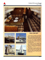
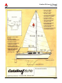
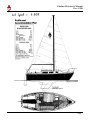
Owners Manual
(Pre-1988)
This manual contains the complete text of the Catalina 25 Owner’s Manual (“Original Version”) from the Catalina 25/250 National Association’s
website (http://www.catalina25-250.org). It is not a complete, authorized copy of the original C25 Owner’s Manual from Catalina Yachts. The Catalina
Yachts logo is from www.catalinayachts.com.
Catalina 25 Owner’s Manual
Pre - 1988
TABLE OF CONTENTS
FOREWORD......................................................................................................................................................................................2
STEPPING THE MAST....................................................................................................................................................................8
CAUTION.......................................................................................................................................................................................8
RIGGING FOR HOIST LAUNCHING...........................................................................................................................................8
TUNING THE MAST........................................................................................................................................................................9
AT THE DOCK...............................................................................................................................................................................9
FINE TUNING WHILE SAILING................................................................................................................................................10
RIGGING SPECIFICATION SCHEDULE C-25 .........................................................................................................................11
STANDARD .................................................................................................................................................................................11
TALL RIG .....................................................................................................................................................................................11
SPAR AND RIGGING MAINTENANCE .....................................................................................................................................12
............................................................................................................................................................................................................14
BATTERIES.....................................................................................................................................................................................15
BATTERY SELECTOR SWITCH ................................................................................................................................................15
110 VOLT SHORE POWER SYSTEM .........................................................................................................................................15
RECOMMENDED OUTBOARD ENGINE ..................................................................................................................................18
OUTBOARD BRACKET .............................................................................................................................................................18
FUEL STORAGE..........................................................................................................................................................................18
TRAILERING ..................................................................................................................................................................................19
GENERAL OPERATION AND MAINTENANCE......................................................................................................................20
POP TOP OPERATION................................................................................................................................................................20
ANCHORS AND ANCHORING..................................................................................................................................................20
ANTI-FOULING BOTTOM PAINT.............................................................................................................................................20
ELECTROLYSIS PROTECTION ................................................................................................................................................21
KEEL MAINTENANCE...............................................................................................................................................................21
U.S. COAST GUARD EQUIPMENT RECOMMENDATIONS ..................................................................................................21
FRESH WATER SYSTEM ...........................................................................................................................................................22
MARINE HEAD ...........................................................................................................................................................................22
HOLDING TANK.........................................................................................................................................................................22
ICE BOX DRAIN..........................................................................................................................................................................23
SEACOCKS ..................................................................................................................................................................................23
MANUAL BILGE PUMP .............................................................................................................................................................23
PARTS AND ACCESSORY ORDERS..........................................................................................................................................23
CLOSING WORDS .........................................................................................................................................................................23
CATALINA YACHTS CHECK LISTS .........................................................................................................................................24
BEFORE LEAVING THE DOCK OR MOORING ......................................................................................................................24
BEFORE LEAVING THE BOAT AFTER USE ...........................................................................................................................24
Page 1
Catalina 25 Owner’s Manual
Pre - 1988
FOREWORD
This manual is intended to serve as a guide to the features and operation of the Catalina 25.
Before attempting maintenance or operation of your Catalina 25, please read the Catalina Yachts Limited
Warranty Booklet. Be sure your dealer has completed the registration card contained within the booklet.
The initial launching and rigging of the Catalina 25 should be handled by experienced boat yard personnel
under the direction of your authorized dealer. After the boat is launched, the dealer will complete the last
phase of rigging and mast tuning as described in this manual.
This manual should be used in conjunction with the CATALINA GENERAL HANDBOOK which
discusses care and maintenance, and, also includes practical sailing and safety tips.
The last pages of this text contain a "Pre-Use Check List" and a "Pre Departure Check List". It will be
useful to incorporate these checks into your sailing routine. A regular inspection is the best preventive
maintenance, and will help keep your boat in good condition while in use and insure peace of mind when
the boat is left unattended.
Page 2
Catalina 25 Owner’s Manual
Pre - 1988
Page 3
Catalina 25 Owner’s Manual
Pre - 1988
Page 4
Catalina 25 Owner’s Manual
Pre - 1988
Page 5
Catalina 25 Owner’s Manual
Pre - 1988
Page 6
Catalina 25 Owner’s Manual
Pre - 1988
Page 7
Catalina 25 Owner’s Manual
Pre - 1988
STEPPING THE MAST
CAUTION
The aluminum mast and other metal parts conduct electricity coming in contact with or near an electrical
power line or lightning can cause severe injury or death. Stay away from overhead electrical power lines
when sailing and/or launching the boat.
1. When tailoring your boat always try to undo as little rigging as Possible. It is necessary only to undo
the two forward lower shrouds and the forestay before lowering the mast.
2. Before raising mast, make sure halyards are neatly tied down and that they are on proper sides of the
spreaders. You should never attempt to raise the mast unless the upper shrouds (those that pass over
the spreaders) and the aft lower shrouds are attached to the deck fittings and the turn buckles well
"started" into their barrels. The turnbuckles must not be completely tightened however, because slack
is needed in the shrouds to enable the mast to be fully raised. The backstay should be attached to the
transom chain plate. The upper shrouds, after lower shrouds, and backstay will keep the mast from
falling over when it is raised, therefore, all of these must be attached to the chain plates before the
mast is raised.
3. Make sure that the shrouds and stays are not fouled. Backstay should lie clear of the transom. You
may step the mast on land or while the boat is in the water. It seems to be easier on land because the
boat is still. Also, it keeps other sailors from getting impatient while they wait for you to move out of
the launch area.
4. Walk the mast aft and drop the mast foot into the tabernacle located on top of the deck, keeping the
mast in center line of boat insert the pivot bolt and locking nut.
5. One crew member should pull on a line tied securely to the forestay while another pushes up on the
mast and walks from the cockpit forward. With the mast erect, attach the forestay and forward lower
shrouds.
RIGGING FOR HOIST LAUNCHING
The fixed-keel model Catalina 25 should be launched with the aid of a hoist and slings. The local dealer
and boat yard using hoists can advise you about this and will handle the operation for you. Retractablekeel models are also often launched using a hoist and slings.
Either model boat can be hoist launched with the mast stepped and in place in the vertical position by
releasing the backstay at the turn buckle where it attaches to the transom. However, the remainder of the
mast's shrouds and forward stay must be properly connected to their chain plates. Most importantly,
check that the aft lower shrouds are secure since they will keep the mast from falling forward when the
backstay is disconnected from the transom. Be sure to re- connect the backstay before raising sails or
getting under way.
Page 8
Catalina 25 Owner’s Manual
Pre - 1988
TUNING THE MAST
The mast is held aloft by the Standing Rigging (forestay, backstay, upper shrouds, double lower shrouds).
The term "tuning" refers to adjustment of the standing rigging so that the mast remains "in column" (not
bent) when under load. This is accomplished by following the procedure outlined below:
AT THE DOCK
1. Adjust forestay and backstay so that the mast is straight up and down (perpendicular). Tie a bolt to a
6 to 7 foot long piece of light line to make a quick plumb bob, and tape the free end of the line to the
front of the mast as high up as you can reach. This device will help you determine whether the mast is
perpendicular or not.
2. Adjust upper shrouds so that the mast is straight up and down athwarthships, that is from side to side
as opposed to from bow to stern.
3. The upper shrouds should be firm but not tight. A 50 pound push should deflect the upper shroud
about 1M" at shoulder height.
4. The lower shrouds (4 of them) should be adjusted so that they are looser than the upper shrouds.
While at the dock they should have no slack but also have no tension on them. No lower shroud when
pushed should deflect the mast more than any other shroud when pushed equally hard. If this can't be
achieved, the upper shrouds are too tight. Back off one-half turn at a time on the upper shroud
turnbuckles until the tension on the lower shrouds is brought into balance.
Page 9
Catalina 25 Owner’s Manual
Pre - 1988
FINE TUNING WHILE SAILING
The object of Fine Tuning is to have the mast "in column" (not bent fore or aft or athwartships) when
sailing in conditions typical for your area. This is accomplished through adjustments to the lower shroud
turnbuckles. Here are some points to look for:
1. When sailing on port tack, sight up the mast from the base. If the middle (where the spreaders are) is
sagging to leeward, take up equally on both port lower shrouds until the mast is in column. Repeat
this procedure on starboard tack.
2. If, when sighting up the mast while on port tack, the middle is bent forward (but not to leeward) take
up a turn on the port aft lower shroud and let out a turn on the port forward lower shroud turn buckle.
Reverse these adjustments if the middle of the mast is aft of the "in column position.
3. If a perfectly straight mast is not obtained, the mast head (top) may be curved aft and to leeward. The
mast head should never be "hooked" forward to weather.
All rigging wire used on yachts has a tendency to stretch, especially on a new yacht, or after you have
sailed in heavier wind than you normally experience. Therefore, you should periodically check the
tension on the shrouds and stays, tightening them up if it is required.
Our masts are built to withstand any normal usage but improper tuning or handling can cause problems.
Therefore, it is impossible to guarantee the mast under our current warranty program. Rigging, as well as
tuning becomes ail important when setting up the mast. A knowledgeable person should oversee the
rigging and tuning so as to eliminate the possibility of an eccentric loading which might occur with an
improperly tensioned shroud. Special attention should be given to the initial stretch of the shrouds and a
further gradual stretch of the wire over the first few hard outings.
When making the tuning adjustments while underway, it is advisable to keep the upper and lower nuts on
each turnbuckle snug to keep from having the turnbuckle loosen. Upon completion of the tuning, tighten
the nuts securely.
ALWAYS, before leaving the dock for a day's sail, check all your turnbuckle nuts for tightness.
Also, visually inspect the fittings aloft. MOST MAST FAILURES HAVE BEEN TRACED BACK TO
LOOSENED TURNBUCKLES AND IMPROPER TUNING.
Page 10
Catalina 25 Owner’s Manual
Pre - 1988
RIGGING SPECIFICATION SCHEDULE C-25
STANDARD
NOTE - MAST EXTRUSION = 28' - 0" ------- BOOM EXTRUSION = 10' - 4"
Description
Main Halyard
Jib Halyard
Forestay
Single Backstay
Split Backstay
Backstay Bridle
Forward Lowers
Aft Lowers
Upper Shrouds
S.S. Wire Size
1/8" 7x19
1/8" 7x19
3/16" 1x19
3/16" 1x19
3/16" 1x19
3/16" 1x19
5/32" 1x19
5/32" 1x19
3/16" 1x19
L = Length
27' 8"
29' 2"
29' -10"
32' 3"
26' 4"
5' 8 1/2"
14' 5"
14' 7 1/4"
28' 5 3/4"
No. Reqd
1
1
1
1
1
2
2
2
2
TALL RIG
NOTE - MAST EXTRUSION = 30' - 0" ------ BOOM EXTRUSION = 10' - 4"
Description
Main Halyard
Jib Halyard
Forestay
Single Backstay
Split Backstay
Backstay Bridle
Forward Lowers
Aft Lowers
Upper Shrouds
S.S. Wire Size
1/8" 7x19
1/8" 7x19
3/16" 1x19
3/16" 1x19
3/16" 1x19
3/16" 1x19
5/32" 1x19
5/32" 1x19
3/16" 1x19
L = Length
27' 8"
29' 2"
31' -10"
33' 11 1/4"
28' 2"
5' 8 1/2"
15' 5"
15' 6 1/4"
30' 6 1/2"
No. Reqd
1
1
1
1
1
2
2
2
2
L = Eye to Eye for halyards
L = Eye to end of the threads for shrouds and stays
All dimensions are approximate and subject to change.
Page 11
Catalina 25 Owner’s Manual
Pre - 1988
SPAR AND RIGGING MAINTENANCE
Mill finish aluminum on the standard spar surfaces are protected against corrosion by a thin naturally
formed film of aluminum oxide. Dust, dirt, smoke, salt and traffic fumes will adhere to this film, making
the surface dull and unsightly. Coating the new surfaces with a good paste wax like Vista or Simonize,
will help protect the aluminum oxide from foreign matter. If the surface has become tarnished, a good
high grade cleaner, wax, or polish will help restore the original sheen. Heavier pitting can be removed by
wet sanding with #600 paper prior to polishing and waxing.
Anodized spars need only to be washed with soap and fresh water and waxed each season to maintain the
original finish for many years.
Fill finish aluminum spars may also be painted. Epoxy and polyurethane paint systems have been
specially formulated for use on aluminum spars. The coating manufacturers' instructions should be
followed.
Salt water will gradually stiffen Dacron line. Hosing with fresh water or soaking in warm soapy water
will make the line soft and flexible again. Be sure to rinse line thoroughly. Keep line coiled and stowed
in a dry spot below.
Clean rigging means clean sails. A quick trip aloft with damp rags takes care of this problem. While
aloft, check the entire rig for loose screws, nuts, bolts, cotter pins and chafe which may have resulted from
hard sailing. Periodic inspection of the rig is one of your best insurance against rigging and spar failure.
Keeping halyards tied away from the mast stops the annoying dockside clanking and save the mast finish.
Test the mast light before the mast is raised, this is especially important after the boat has been trailered.
Spreader tips, turnbuckle barrels and clevis pins should be taped or covered with plastic caps to reduce
chafing on the sails. Tape any part of the rigging which is sharp or jagged which may tear the sails when
sailing and coming about.
Page 12
Catalina 25 Owner’s Manual
Pre - 1988
Page 13
Catalina 25 Owner’s Manual
Pre - 1988
Page 14
Catalina 25 Owner’s Manual
Pre - 1988
BATTERIES
The 12 volt electrical system is powered by 12 volt DC, 70 amp hour wet cell marine grade battery
Battery #1 is located under the starboard Seat-berth aft of the water tank; the battery is housed in a plastic
container and is secured with a tie down to prevent movement at extreme angles of heel.
The optional second battery is located on the port side under the settee or dinette seat, the second battery
is also housed in a plastic container and secured to prevent movement.
When the optional second battery is installed a battery selector switch is provided.
Battery box covers should be kept on at all times to prevent accidental arcing at the terminals.
BATTERY SELECTOR SWITCH
The circular spark-proof switch has the marking 1, 2, and "ALL" as well as "OFF".
If your outboard motor is equipped with an alternator and electric starter NEVER pass through the OFF
position to change from one battery to the other with the engine running or the alternator diodes will be
burned out. Switching from one battery to another should only be done with the engine stopped. If both
batteries are of equal charge, keep the selector switch on ALL position, and use ALL to start the engine if
both batteries are low.
110 VOLT SHORE POWER SYSTEM
The optional 110 volt AC system is connected to shore power by a grounded, twist-lock- connector
mounted on the outside of the port cockpit coaming. Always connect the power cord to the boat and then
to the Shore power source. When removing the cord unplug at the shore connection first.
A twenty-five Amp circuit breaker is located the aft bulkhead of the galley. Duplex outlets for the 110
Volt system are located on both sides of the main cabin. Be certain that all 110 V. appliances, other than
lamps, have an adequate grounding connector. Wet feet or moist atmosphere increase the potential shock
hazard.
Always use a marine type three (3) prong connector w/locking ground for all shore power connections.
Page 15
Catalina 25 Owner’s Manual
Pre - 1988
Page 16
Catalina 25 Owner’s Manual
Pre - 1988
Page 17
Catalina 25 Owner’s Manual
Pre - 1988
RECOMMENDED OUTBOARD ENGINE
An outboard engine of 7.5 to 10 horsepower should be adequate to propel the Catalina 25 at hull speed
under usual conditions.
A larger engine will not increase hull speed and may add additional unnecessary weight in the stern.
Long shaft engines are preferable; however, standard length shaft engines should be adequate for most
conditions.
OUTBOARD BRACKET
The factory installed outboard bracket is spring loaded to assist lifting and lowering the engine. It locks
in both the up and down position. To release the lock in either position a downward pressure is applied to
the red handle while lifting or lowering the engine. The motor should not be lifted clear of the water
while it is running.
When under sail, the motor should be kept in the raised position and tilted forward so that the propeller is
clear of the water to eliminate unnecessary drag.
The motor bracket manufacturer's recommended maximum horsepower should not be exceeded.
FUEL STORAGE
It is recommended that any enclosed compartment used for fuel storage be vented. The optional factory
installed vents meet current, Coast Guard and State requirements when fuel is stored in the port cockpit
locker on the molded storage platform.
Gasoline fumes are heavier than air and will accumulate in the bottom of the compartment, if not properly
vented. This creates a fire and explosion hazard. Be sure there is a properly installed ventilation system
that complies with Coast Guard and State regulations before storing gasoline in any enclosed
compartment.
Portable fuel tanks should be secured in place before getting under way.
Page 18
Catalina 25 Owner’s Manual
Pre - 1988
TRAILERING
The Catalina 25 is an easy boat to trailer when certain precautions have been properly heeded.
In addition to the remarks in the GENERAL HANDBOOK, the following suggestions will prove helpful.
1. Be sure to read the Trailer Manufacturers Instructions and Warranty carefully, and do not exceed the
Manufacturers gross vehicle weight for trailer boat and gear.
2. Check tongue weight. Most trailers tow well with 7 to 10 percent of the Gross Trailer and load weight
on the tongue. If the trailer tends to "fish tail" add tongue weight by moving weight forward or the
trailer axles aft.
3. Test the brakes by operating the master cylinder manually.
4. Inspect the winch cable for broken strands or fraying.
5. Tie the mast and boom securely to the bow and stern pulpits, the spars should also be supported in the
middle by the cabin top. Pad the mast at all contact points to prevent damage.
6. In the retractable-keel model, check that the keel has been cranked down until it rests firmly on the
trailer's rubber support wedge or roller. The rubber support wedge should bear the complete weight of
the keel. Immediately before launching, raise keel to maximum up position to clear trailer.
7. Fixed-keel boats as well as retractable-keel boats should be seated properly on the trailer; that is, not
ajar or tilted, and with the bow properly snugged into the rubber wedge at the front of the trailer.
Fixed keel boats should have the weight of the boat bearing on the keel, not the padded upright
supports.
8. Follow normal trailer procedures of connecting lights and safety chain, and be sure your hitch is wellsecured. Always test lights before leaving ramp area.
9. Do not allow anyone aft of the transom during launching or loading, who could be injured if the boat
were suddenly dislodged from the trailer.
Page 19
Catalina 25 Owner’s Manual
Pre - 1988
GENERAL OPERATION AND MAINTENANCE
POP TOP OPERATION
If your boat is equipped with a "pop top" hatch, the following notes will aid in its operation.
First of all, the pop top can be used in two different positions. When the pop top is in the down position,
the smaller sliding hatch serves as access to the cabin. When the pop top is in the up position, access to
the cabin is greatly increased and of course, so is the available headroom. To put the pop top in the up
position you must go inside the cabin. The top is raised by lifting upward and forward at the same time.
With the pop top in the fully raised position, reach forward to the pop top slide lock and look the top to
the mast.
In light winds you can sail with the pop top in the raised position, but in heavier winds it is recommended
that you keep it closed and fastened down, along with all other hatches.
ANCHORS AND ANCHORING
Under normal weather conditions in a protected anchorage an anchor in the 9-13 pound range and of the
"danforth type" may be used as a bow anchor in ordinary conditions. This anchor will only be effective
with at least 12 feet of 1/4 inch or heavier gauge chain and at least 200 feet or more of 7/16" or heavier
nylon line. An 8 pound stern anchor will require about 150 feet of scope and 10 feet of chain.
Under adverse weather conditions as much as a 20 pound bow anchor could prove necessary, and possibly
a plough-type anchor might be required.
Inquire in your local area about anchoring procedures relative to the place you plan to visit. Get the
opinion of several experienced people and always play it on the safe side in "making up" your anchor
ahead of time for emergency use. Do not forget to wire all shackle pins so they cannot come loose
underwater.
Remember: Lighter anchors are made more effective by increasing the scope, i.e., the ratio of length of
line and chain to depth of water. A 7:1 ratio is recommended. This means using 7 feet of anchor line for
each foot in depth of water. An anchor is a necessity aboard any boat; it is recommended you have a
usable anchor aboard whenever you leave the dock.
ANTI-FOULING BOTTOM PAINT
Anti-fouling paint should be applied to the bottom if it is to be moored in either fresh or salt water for any
length of time. There are many brands available. Anti-fouling paint prevents the growth of algae,
barnacles and other fouling organisms on underwater surfaces. If this paint has been applied at the
factory, no action is necessary at the time of launching.
The anti-fouling paint used at the factory is a vinyl-base copper bearing type available either in red or
blue. For those owners who apply antifouling paint themselves, it should be noted that most brands
require all underwater fiberglass surfaces to be very carefully sanded and primed immediately prior to the
first application on a new boat. In any event, the instructions of the manufacturer of the brand of paint
used should be followed.
Page 20
Catalina 25 Owner’s Manual
Pre - 1988
ELECTROLYSIS PROTECTION
If you decide to keep your retractable-keel model in the water, especially salt water. Bottom paint is a
must, plus periodic cleaning and removal of marine growth from the keel trunk slot. The possibility of
corrosion to the keel and keel fittings is greatly increased. Keeping a retractable-keel model in salt water
for lengthy periods is not recommended.
Should you decide to keep a retractable-keel model in the water at a slip or mooring for extended periods
where electrolysis is a potential problem, the following suggestions may help to protect the keel assembly.
The keel pivot pin is made of siliconbronze, the hinge castings are of brass, and the keel itself is made of
iron. To retard electrolytic action which will "eat" away the metals, drill and tap the side of the keel (near
the forward edge) as close to the keel Pivot assembly as possible. Then attach a teardrop shaped "zinc."
Keeping the keel in the raised position will help prolong the life of the cable (7x19, 1/4" S.S.) by keeping
as much of it out of the water as possible.
KEEL MAINTENANCE
Iron keels must be sealed to prevent rusting. You may paint the keel itself with rust retardant paint like
the commercially available "Rust-o-leum" or zinc chromate paints.
The fixed keel or retractable keel may also be painted with a two part epoxy paint system to prevent
rusting. Most epoxy systems require stripping the keel to bare metal and filling with a chemically
compatible filler compound. The paint manufacturer’s instructions should be followed.
To remove the keel you will note that the keel pivots on a rod, secured by two cast fittings recessed into
the hull. Should the keel require removal at any time, these castings may be unbolted by removing the
stainless steel cable and the four 3/8 x 16" bolts from the underside. Make sure that the keel is well
supported before removing these fastenings.
When replacing the keel be sure to use lock washers and a liquid locking agent like "lock tight". The
bolts should be reset with a torque wrench to 35 lbs. ea.
U.S. COAST GUARD EQUIPMENT RECOMMENDATIONS
U.S. Coast Guard Recommended minimum Equipment list.
The following list, prepared by the U.S. Coast Guard represents the minimum equipment necessary for
the safe operation of a 25 foot outboard power sail boat similar to the Catalina 25.
1. (1) Numbering in accordance w/ state regulations
2. (1) Sound producing device, audible for 1/2 mile (Horn, Whistle, Bell)
3. (1) Type I, II or II life preserver for each person aboard.
4. (1) Type IV Device (throwable life ring or buoy)
5. (1) B-l type fire extinguisher, dry chemical, USCG approved.
6. Lights if night operation is intended, in accordance with USCG regulations.
Page 21
Catalina 25 Owner’s Manual
Pre - 1988
FRESH WATER SYSTEM
The galley is supplied fresh water from a 16 gallon high density plastic tank located under the starboard
settee. The tank is filled thru the vent cap mounted directly on the tank or thru the optional deck fill plate,
located on the starboard side deck. The deck fill is labeled water.
The threads of the fill plate cap should be lightly coated with petroleum jelly or another non toxic
lubricant to prevent corrosion between the plate and the cap.
MARINE HEAD
Boats manufactured before January 31, 1977, may have an overboard discharge marine head. The toilet is
supplied with servicing instructions. Operation instructions are printed on the toilet pump housing. Read
the instructions thoroughly and be sure that all persons who might be using the head understand its
operation. Parts and spares may be obtained directly from the toilet manufacturer or your servicing
Catalina dealer.
The marine head thru-hull valves should be kept closed when not operating the head to avoid the
possibility of water entering the boat due to failure of the internal toilet valve.
HOLDING TANK
The optional holding tank is made from high density polypropylene plastic. The tank capacity is 14 U.S.
Gallons. It is located under the forward end of the settee or dinette seat on the port side.
The vent is located on the port side deck near the main chain plate. The vent line (1/2" I.D.) must be kept
clear. If it becomes clogged it should be flushed with fresh water, this can be done from the deck vent
using a garden hose.
The tank is emptied by a shore side pump thru the deck plate marked "Waste" on the port side deck.
Waste should not be stored for long periods of time. The tank should be emptied and flushed regularly.
A simple method of checking the level of the tank is to put a flash light, lens down, on the top of the tank,
then look at one side of the tank and you can see the fluid level in the tank.
Page 22
Catalina 25 Owner’s Manual
Pre - 1988
ICE BOX DRAIN
The ice box drain is tapped to the galley sink drain. The ice box drain is fitted with a separate valve. This
should be kept closed when sailing to prevent salt water from backing up into the ice box when the boat is
heeled. In areas where overboard discharge is prohibited the drains can be disconnected and led to a jug
in the bilge.
SEACOCKS
All underwater thru-hull fittings are equipped with gate valves. Close all gate valves when leaving the
boat, especially for an extended period of time.
To close seacocks, turn clockwise; to open, turn counter-clockwise.
It is good practice to operate the gate valves at least once a month to keep them in good working order
Check the packing glands on all gate valves yearly to avoid water seepage.
MANUAL BILGE PUMP
The manual bilge pump is located in the port cockpit locker. The handle is stored in a clip fitting just
above the pump inside the locker. Insert the handle through the water-tight fitting in the cockpit to
operate the pump.
The pump pick-up is in the keel stub under the main cabin sole. The pump hoses are 1" I.D.
PARTS AND ACCESSORY ORDERS
Catalina's interest in both customer and product continues long after you have commissioned your
Catalina 25.
Within the limits of our specifications, the company's Parts Department is ready to serve your nearest
dealer quickly and efficiently. All replacement parts or accessories are delivered through your dealer. He
must have detailed information from you to be certain we send the parts required.
CLOSING WORDS
The builder would like to take this opportunity to wish you season after season of sailing enjoyment in
your new Catalina 25.
We have prepared these texts with that goal in mind, believing that knowledge of the boat and awareness
of safety procedures will lead to increased sailing pleasure for you and your family.
Take care of your boat and take the time to learn and practice good seamanship.
Page 23
Catalina 25 Owner’s Manual
Pre - 1988
CATALINA YACHTS CHECK LISTS
BEFORE LEAVING THE DOCK OR MOORING
1. Visually inspect the standing rigging. Be sure that turnbuckle nuts are tight or cotter pins secure and
covered to prevent chafe, halyards are free and not tangled.
2. Make-up the anchor and line. These should be ready for immediate use, stored on deck or in the
forward anchor locker.
3. A throwable, approved lifesaving device should be on deck, available to the helmsman, in accordance
with Coast Guard Recommendations.
4. Test running lights.
5. Check water tank.
6. Check fuel tank level.
7. Secure loose objects on deck and below.
BEFORE LEAVING THE BOAT AFTER USE
1. Close all thru-hull valves.
2. Any salt spray should be rinsed from the deck and rigging with fresh water to prevent corrosion and
preserve the finish. 3. Relieve pressure in stove fuel tank if fitted.
3. Leave ice box lid ajar for ventilation.
4. Check bilge water level, pump if necessary.
5. Set battery selector switch to "off".
6. Check mooring or dock lines for secure attachment.
7. Tie off halyards to shrouds to prevent unnecessary noise and preserve mast finish.
8. Secure mooring lines or dock lines, place fenders when required.
Page 24