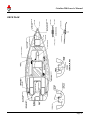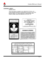
1
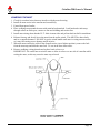
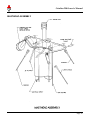
Owners Manual
This manual contains the complete text of the Catalina 250 Owner’s Manual (1st Edition 12-1-94; 2nd Edition 8-9-95) from the Catalina 25/250
National Association’s website (http://www.catalina25-250.org). It is not a complete, authorized copy of the original C250 Owner’s Manual from
Catalina Yachts. The Catalina Yachts logo is from www.catalinayachts.com.
Catalina 250 Owner’s Manual
TABLE OF CONTENTS
PREFACE..................................................................................................................................................................................... 3
FORWARD................................................................................................................................................................................... 4
YACHT INFORMATION AND SPECIFICATIONS .............................................................................................................. 9
ADDITIONAL SPECIFICATIONS........................................................................................................................................ 10
DIMENSIONS..................................................................................................................................................................... 10
COMPARATIVE DATA (w/ Water ballast) ........................................................................................................................ 10
SAILS .................................................................................................................................................................................. 10
TANKAGE AND CAPACITIES........................................................................................................................................... 10
RIGGING ................................................................................................................................................................................... 11
OPTIONAL MAST RAISING SYSTEM................................................................................................................................ 11
STEPPING THE MAST ...................................................................................................................................................... 11
LOWERING THE MAST..................................................................................................................................................... 13
RIGGING LENGTH ............................................................................................................................................................... 14
SPREADER ASSEMBLY ...................................................................................................................................................... 15
MASTHEAD ASSEMBLY..................................................................................................................................................... 16
MAINSTAY AND BOOM VANG SYSTEM ......................................................................................................................... 17
TUNING THE MAST ............................................................................................................................................................. 18
AT THE DOCK (First part of tuning)................................................................................................................................. 18
TUNING UNDER LOAD (Second part of tuning) .............................................................................................................. 20
MAIN SAIL REEFING ........................................................................................................................................................... 21
SAIL PLAN............................................................................................................................................................................. 22
OTHER SYSTEMS.................................................................................................................................................................... 23
CENTERBOARD SYSTEM ................................................................................................................................................... 23
WATER BALLAST SYSTEM................................................................................................................................................ 24
MANUAL BILGE PUMP ....................................................................................................................................................... 24
USEFUL TIPS......................................................................................................................................................................... 24
ELECTRICAL......................................................................................................................................................................... 26
BATTERIES ........................................................................................................................................................................ 26
ELECTROLYTE LEVEL ..................................................................................................................................................... 26
CHARGING THE BATTERY:............................................................................................................................................. 26
DISCHARGED STATE:...................................................................................................................................................... 27
CLEAN CONNECTIONS: .................................................................................................................................................. 27
ELECTRICAL SYSTEM ........................................................................................................................................................ 27
DC - 12 VOLT SYSTEM ..................................................................................................................................................... 27
WIRING DIAGRAM ........................................................................................................................................................... 28
NAVIGATION LIGHTS ...................................................................................................................................................... 29
PREVENTIVE MAINTENANCE......................................................................................................................................... 29
ACCOMODATION PLAN ..................................................................................................................................................... 30
DECK PLAN........................................................................................................................................................................... 31
RECOMMENDED OUTBOARD ENGINE ........................................................................................................................... 32
POP TOP OPERATION.......................................................................................................................................................... 32
RECOMMENDATIONS FOR TRAILERING ....................................................................................................................... 32
GENERAL SAFETY TIPS ..................................................................................................................................................... 33
Page 1
Catalina 250 Owner’s Manual
REQUIRED MINIMUM SAFETY EQUIPMENT ................................................................................................................. 34
FIRE EXTINGUISHER (S) ................................................................................................................................................. 34
PERSONAL FLOATATION DEVICES............................................................................................................................... 34
HORN ................................................................................................................................................................................. 34
SUGGESTED SAFETY EQUIPMENT AND SAFETY PACKAGE..................................................................................... 34
ANCHOR, ANCHORING, AND MOORING ........................................................................................................................ 35
LIGHTNING PRECAUTIONS............................................................................................................................................... 35
WARNING LABELS.............................................................................................................................................................. 37
COMMISSIONING CHECKLIST.......................................................................................................................................... 38
PRE-LAUNCH CHECK...................................................................................................................................................... 38
IN WATER CHECK ............................................................................................................................................................ 38
MAINTENANCE GUIDE....................................................................................................................................................... 40
PRE-USE MAINTENANCE:............................................................................................................................................... 40
MONTHLY MAINTENANCE.............................................................................................................................................. 40
SEASONAL MAINTENANCE:............................................................................................................................................ 40
CARE AND MAINTENANCE OF YOUR RUDDER........................................................................................................... 45
BOTTOM PAINT PREPARATION ..................................................................................................................................... 45
SPAR AND RIGGING MAINTENANCE ............................................................................................................................ 45
SAIL MAINTENANCE ........................................................................................................................................................ 47
INTERIOR CUSHION, FABRIC COVER CLEANING....................................................................................................... 48
Page 2
Catalina 250 Owner’s Manual
PREFACE
Congratulations on the acquisition of your new Catalina 250. All Catalina yachts are designed and built
with care using quality materials to assure you years of sailing enjoyment with a minimum of upkeep and
maintenance.
Before attempting maintenance or operation of your Catalina 250, please read the Catalina Yachts
Limited Warranty booklet and fill out the enclosed warranty registration card.
The registration card enables Catalina to inform you of developments and modifications to enhance the
performance or comfort of your yacht. It is also important to be able to contact owners to comply with
Coast Guard notification requirements.
The launching and rigging of the Catalina 250 should be handled by experienced boat yard personnel
under the direction of your authorized dealer.
The index page lists the contents of this manual. Warranties and information installed optional equipment
have been included when available and applicable.
Maintaining your yacht properly can become a satisfying part of your sailing activities. A regular
inspection is the best preventive maintenance. It will help keep your boat safe and in good condition
while in use, and insure peace of mind when the boat is left unattended
Take good care of your boat and take the time to learn and practice good seamanship.
Page 3
Catalina 250 Owner’s Manual
FORWARD
This manual is not intended to provide sailing instructions. It is assumed the operator will consult books
written for that purpose, or take sailing lessons or courses to gain the knowledge necessary for the safe
operation of the vessel.
The systems descriptions and illustrations in this manual apply to boats built at the time of publication.
Our policy of constant improvement necessitates that changes have been made to the Catalina 250 since
its introduction. Therefore, these illustrations and descriptions may not apply to boats built before the
time of publication.
Owners of earlier hulls, who have questions not answered herein should consult with their local Catalina
dealer, or write to Catalina Yachts. Please include your hull number in all correspondence.
The maintenance checklists contained within this manual are intended as guidelines for boats in normal
service under typical conditions.
Climate and use will vary and may require additional or special maintenance. Consult with your local
boatyard or Catalina dealer for specific maintenance and precautions recommended for your purposes and
climate.
Caution: The aluminum and other metal parts conduct electricity. Coming in contact with or near an
electrical power line or lightning can cause severe injury or death. Stay away from overhead electrical
power lines when sailing and/or launching the boat.
Equipment manufacturer's literature will be included with this manual only when available and applicable
to the hull number for which the manual is intended. This information has been prepared and supplied by
the equipment manufacturer and may illustrate installations or applications which vary from CATALINA
standard practice. CATALINA is not responsible for the accuracy of information supplied by equipment
manufacturers.
Page 4
Catalina 250 Owner’s Manual
Page 5
Catalina 250 Owner’s Manual
Page 6
Catalina 250 Owner’s Manual
Page 7
Catalina 250 Owner’s Manual
Page 8
Catalina 250 Owner’s Manual
YACHT INFORMATION AND SPECIFICATIONS
Page 9
Catalina 250 Owner’s Manual
ADDITIONAL SPECIFICATIONS
DIMENSIONS
Distance from Waterline to Masthead
33'-4"
Maximum Headroom w/ Pop Top down
4'-8"
Maximum Headroom w/ Pop Top up
6'-4"
COMPARATIVE DATA (w/ Water ballast)
Displacement to Length
167.49
Sail Area to Displacement
19.8
Theoretical Hull Speed
6.17
SAILS
Sail Area (100% Fore
triangle)
265.0 sq. ft.
Mainsail 6 oz. Cloth
137.5 sq. ft.
Standard Jib 6 oz. Cloth
133.5 sq. ft.
I: 29.00ft.
P: 24.50 ft.
J: 9.00.ft.
E: 11.00 ft.
TANKAGE AND CAPACITIES
Holding tank
Thetford Porta Pottie
Ice Box 48 qt.
Berths
Cooler under Galley
(1) Double "V" berth; (1) Double Aft berth
Specifications and equipment subject to change without notice
Page 10
Catalina 250 Owner’s Manual
RIGGING
OPTIONAL MAST RAISING SYSTEM
STEPPING THE MAST
Caution: The mast and other metal parts conduct electricity. Coming in contact with or near an
electrical power line or lightning can cause severe injury or death. Stay away from overhead electrical
power lines when sailing and/or launching the boat.
When trailering your boat always try to undo as little rigging as possible.
1. Before raising the mast, make sure halyards are neatly tied down and that they are on proper sides
of the spreaders. You should never attempt to raise the mast unless the upper shrouds (those that
pass over the spreaders) and the lower shrouds are attached to the deck fittings and the turnbuckles
are well "started" into their barrels by at least 3/4 of an inch. The turnbuckles must not be
completely tightened however, because slack is needed in the shrouds to enable the mast to be
fully raised. The backstay should be attached to the transom chain plate.
The upper shrouds, aft lower shrouds, and backstay will keep the mast from falling over when it is
raised, therefore, all of these must be attached to the chain plate before the mast is raised. Check
that the spreaders are secure and that spreader boots are secure.
2. Make sure that the shrouds and stays are not fouled. Backstay should lie clear of the transom.
3. Extend mast carrier and roller support at the front of the trailer to their highest positions and
secure with pin.
4. Slide the mast aft over the mast carrier until the foot is at the mast step and install the bolt
connecting the mast step and the mast. At this time, you should check that all the mast lights are
functioning properly.
5. Check for overhead wires that may interfere with the mast raising. Make sure the trailer is on
level ground.
6. Verify that upper and lower shrouds are connected to chain plate (A) and not caught or wrapped in
a way that would cause them to kink or interfere with raising the mast.
7. Release hook from bow eye and lead hook and strap through the two (2) rollers at the trailer post.
(B)
8. Place webbing strap around the mast just below the spreaders 8 secure at that height with the main
halyard. Fasten main halyard to a cleat on starboard side of mast (D). Using the supplied line, tie
a bowline loop through both ends of the webbing strap and another loop securely attached to the
hook at the end of the winch strap. WARNING: Main halyard MUST be properly secured.
Failure to do so may result in serious injury.
9. Install mast raising short shrouds w/ T- bolts in mast sides and pelican hook on bail in stanchions.
(E) These shrouds should be slightly slack to allow self-centering during raising and lowering
maneuvers.
10. Crank the winch on the trailer, (F) until mast is vertical. Connect forestay to stem fitting to secure
the mast in position.
11. If backstay was not connected, do so at this time (at transom), and remove raising shrouds.
12. Lower main halyard to lower webbing strap. Release hook, then adjust rig as desired.
Page 11
Catalina 250 Owner’s Manual
Page 12
Catalina 250 Owner’s Manual
LOWERING THE MAST
1. Check for overhead wires that may interfere with the mast lowering.
2. Install aft mast carrier in the transom and extend fully.
3. Extend front post of trailer.
4. Place webbing strap around the mast with main halyard attached. Lead hook and winch strap
through rollers on trailer post, connect to line and webbing and tension line.
5. Install mast raising short shrouds W/ T- bolts in mast sides and pelican hook on bail in stanchions.
6. Release forestay and slowly lower the mast from the trailer winch. This MUST be done slowly
and in a controlled manner. DO NOT let go the winch handle until mast is resting on mast carrier
or it may fall causing severe damage and/or injuries.
7. When the mast reaches the roller at the aft mast carrier (set to highest position), remove the bolt
from the mast step and slide the mast fwd. To rest in the bow mast carrier.
8. Remove webbing, raising shrouds and replace hook on bow eye.
IMPORTANT: Be careful not to twist the mast or allow it to move to one side of centerline while
raising the mast, as this may cause the mast step to break.
Page 13
Catalina 250 Owner’s Manual
RIGGING LENGTH
Page 14
Catalina 250 Owner’s Manual
SPREADER ASSEMBLY
Page 15
Catalina 250 Owner’s Manual
MASTHEAD ASSEMBLY
Page 16
Catalina 250 Owner’s Manual
MAINSTAY AND BOOM VANG SYSTEM
Page 17
Catalina 250 Owner’s Manual
TUNING THE MAST
Your mast is held aloft by the standing rigging (forestay, backstay, upper shrouds and lower shrouds).
The term "tuning" refers to adjustment of the standing rigging so that the mast remains "in column" when
under load. This is accomplished by following the procedure outlined below:
AT THE DOCK (First part of tuning)
1. Adjust forestay and backstay so that the rake (fore and aft angle of the mast) is approximately four
(4) inches. In order to measure the rake, tie a weight from the main halyard to act as a plumb bob,
and measure the horizontal distance between the halyard and the aft face of the mast.
2. Adjust upper shrouds so that the mast is vertical from side to side. To verify this, using the main
halyard, measure the distance from the masthead to the center of the pin a the chain plates; repeat
for opposite side and adjust upper shrouds as necessary
Page 18
Catalina 250 Owner’s Manual
3. Once the mast is straight side to side, increase tension of upper shrouds taking an equal number of
turns per side, until the fore and aft pre-bend induced reaches approximately 1 ½ inches.
4. The lower shrouds should be adjusted slightly looser than the uppers. The shrouds will help
control the amount of pre-bend in the rig.
NOTE: Rigging tensions may be measured with LOOS & Co. Model B tension gauge.
Page 19
Catalina 250 Owner’s Manual
TUNING UNDER LOAD (Second part of tuning)
The tuning at the dock gives an initial positioning of the mast but it is essential to tune the rig under
load in order to compensate for dynamic forces that occur while sailing.
1. While sailing normally to windward, at approximately 15 to 20 degrees of heel; sight up the mast,
along the aft face, from the deck If the middle of the mast (where the spreaders are) sags to
leeward in relation with the top of the mast, take up on the weather side lower shrouds until the
mast is straight If the top of the mast sags to leeward in relation with its center, then take up on the
weather side upper shrouds. Repeat this procedure on both tacks.
2. Observe carefully the behavior of the leeward shrouds. They should never be loose. All rigging
wire used on yachts has a tendency to stretch, especially on a new yacht, and after you have sailed
in heavier wind than you normally experience. Therefore, you should periodically check the
tension of the shrouds and stays, tightening them up if it is required. Our masts are built to
withstand any normal usage, but improper tuning or handling can cause problems. Rigging as
well as tuning becomes all important when setting up the mast. A knowledgeable person should
oversee the rigging and tuning so as to eliminate the possibility of an eccentric load which might
occur with an improperly loaded shroud. Special attention should be given to the initial stretch of
the wire over the first few hard outings. ALWAYS, before leaving the docks check all your
turnbuckles for tightness.
MOST MAST FAILURES HAVE BEEN TRACED TO LOOSE TURNBUCKLES AND
IMPROPER TUNING.
IMPORTANT:
Final tuning of the mast depends on local conditions and the cut and set of your sails. Consult your
dealer or sail maker for advice. More detailed information on this subject can be found in Wallace
Ross' "Sail Power", published by Alfred A. Knopf in New York
Page 20
Catalina 250 Owner’s Manual
MAIN SAIL REEFING
Reefing should always be done before it becomes necessary. Some sailors use the rule of thumb, if the
thought of reefing occurs to you, it is time to reef. Sailing at extreme angles of heel 25 degrees or more,
is not efficient, fast or comfortable.
Page 21
Catalina 250 Owner’s Manual
SAIL PLAN
Page 22
Catalina 250 Owner’s Manual
OTHER SYSTEMS
CENTERBOARD SYSTEM
The Catalina 250 features a centerboard which is operated from the cockpit. The 6:1 purchase system is
located below decks, under the cabin ladder and the tail exits to the cockpit thru the fitting where the
mainsheet base is attached. To lift the centerboard pull from the rope tail and fasten to the cleat located
below the mainsheet base. To lower it, release the rope tail in a controlled manner until the centerboard is
fully down.
You will note that the centerboard pivots on a bronze fitting recessed into the hull. Should the
centerboard require to be removed at any time, this casting may be unbolted by removing the four fixing
bolts from the underside. Make sure that the centerboard is well supported before removing the fasteners.
If you decide to keep your boat in the water for an extended period of time, bottom paint (anti-fouling) is
a must as is the periodic cleaning and removal of growth from the centerboard and centerboard trunk.
Page 23
Catalina 250 Owner’s Manual
WATER BALLAST SYSTEM
The Catalina 250 is ballasted by water in a tank below the cabin sole. The tank must be filled before
sailing or powering the 250 to insure the stability necessary for safe and efficient operation.
There are two controls for the water ballast tank:
THE WATER INLET VALVE is located under the bottom step of the cabin ladder. To open the valve,
rotate the handle counterclockwise on the threaded rod and then push down. To close the valve rotate the
handle clockwise pulling the threaded rod up until resistance is felt then approximately one half turn more
to seat the seal.
THE TANK AIR VENT outlet is located on deck in the port side of the anchor locker. To remove the
expansive plug which seals the vent, lift the handle to the vertical position and pull the plug out. When
the plug is replaced push the handle to horizontal to expand the plug and seal the vent.
The 250 should be launched with the valve closed; an empty ballast tank will make the boat float higher
which will make it easier to get the boat off the trailer. Fill the ballast tank immediately after launching
1. Remove the vent plug.
2. Open the inlet valve- allow approximately four minutes for the tank to fill.
3. Check the air vent to insure the flow of air evacuating the tank has stopped.
4. Insert the air vent plug.
5. Close the inlet valve.
6. A visual check to insure the tank is filled can be made at the vent hose fitting under the "V" berth
forward. There will be water visible in the clear vent hose to the level of the waterline when the
tank is filled.
The tank is emptied by removing the 250 from the water with the air vent and the inlet valve open. The
tank will start to drain as the boat is pulled out of the water on the trailer and will empty in approximately
seven minutes on level ground.
MANUAL BILGE PUMP
The manual bilge pump is located in the port cockpit coaming. Insert the handle through the watertight
fitting in the cockpit to operate the pump. The pump intake hose (I~ inside diameter is in the bilge sump
under the aft berth on the centerline
USEFUL TIPS
1. Don't trailer or store the 250 out of the water with water in the ballast tank.
2. Occasionally coat the threads of the inlet valve rod with a silicone grease or other non-water soluble
high quality lubricant.
3. Inspect the air vent clear tubing for damage or debris which may clog the tubing.
Page 24
Catalina 250 Owner’s Manual
4. Check the seat of the rubber gasket between the hull and the valve plate for marine growth or debris
which would prevent a good seal.
5. When keeping the 250 in the water for long periods of time a few ounces of chlorine bleach may be
added to the ballast tank water thru the air vent to prevent growth inside the tank, rinse the vent hose
with fresh water after adding chlorine.
6. Do not drill holes in or fasten anything to the top of the ballast tank.
7. Through hulls for a depth sounder or knot-meter may be installed thru the hull in the square recess in
the water tank under the aft berth.
8. Do not store the 250 in the water where temperatures may cause the water ballast to freeze.
Page 25
Catalina 250 Owner’s Manual
ELECTRICAL
BATTERIES
Your electrical system is powered by a marine grade 12-volt deep cycle, 90-amp hour battery.
Attention should be given to maintaining the proper level of distilled water. Do not overfill.
The batteries are provided with a tie down to prevent tipping over at extreme angles of heel. Be sure
these tie downs are fastened securely.
With proper care, the battery installed in your Catalina 250 will provide long and satisfactory service.
Proper care is not difficult, if a few basic points arc kept in mind:
Your battery should be examined periodically for any cracks or breaks in the case or cover, and any
cracks in the sealing compound. If there is any damage, the battery should be repaired at once.
WARNING: The electrolyte in a battery is a solution of sulfuric acid. If any should enter the eyes,
rinse immediately with large amounts of fresh water and seek medical attention. Electrolyte spilled on
skin should be rinsed well with fresh water also. Even a small amount of electrolyte spilled on
clothing will destroy the clothing.
ELECTROLYTE LEVEL
The electrolyte level in a battery should never be allowed to fall low enough to expose the plates.
This not only results in a loss of battery capacity while the battery is low, but wit cause hardening of
the active material on the battery plates. This will result in a permanent loss of battery capacity.
CAUTION! Use only pure distilled water to replenish electrolyte levels. The water from many city
water supply systems is unsatisfactory for battery use.
CHARGING THE BATTERY:
Before adding water, a hydrometer reading of the battery should be taken. If the reading shows the
battery to be above 1.225 specific gravity, the battery has a sufficient charge. If the reading is below
1.225, the battery should be removed for bench charge.
IMPORTANT: Do not leave your batteries on charge for more than forty-eight (48) hours. If there
is no rise in voltage or specific gravity in a period of two hours, further charging is useless and may
damage the battery beyond repair.
Once charged, the battery should have a specific gravity of at least 1.260. If this cannot be reached,
the battery should be inspected by a battery supplier. The batteries should be checked often to ensure
that they do not run down. Check that all battery cells keep an even fluid level and that the fluid is
about 3/8" above the top of the separators.
If one or two cells have lower fluid levels, it is a good indicator that something is wrong with the
battery, and it should be checked.
Page 26
Catalina 250 Owner’s Manual
DISCHARGED STATE:
Leaving a battery in a discharged state for any length of time can also result in a permanent loss of
capacity for the battery. Since it will freeze at relatively low temperatures, leaving it in the cold can
destroy the battery.
CLEAN CONNECTIONS:
Keep the battery connections clean and tight. A cupful of strong baking soda solution and a
toothbrush will clean corrosion from the terminals and neutralize any spilled acid. (Do not allow any
of the solution to enter the battery cells}. A coating of petroleum jelly on the battery terminals will
inhibit corrosion.
ELECTRICAL SYSTEM
The Catalina 250 is equipped with a standard 12 volt DC system. The wiring is run to prevent chaffing or
contact with water, where possible, and is supported as needed. We recommend that you check alt the
connections at least once a year for corrosion, loose fittings, etc.
DC - 12 VOLT SYSTEM
The DC system is powered by one deep cycle battery located aft of the aft berth. The DC electrical
system is controlled by a main breaker panel with switches for running lights, interior lights and
accessories. The interior lights are also controlled by individual switches on the lights themselves.
Page 27
Catalina 250 Owner’s Manual
WIRING DIAGRAM
Page 28
Catalina 250 Owner’s Manual
NAVIGATION LIGHTS
Navigation lights should be used in accordance with the rules and regulations of the waters in which
you intend to sail.
Generally, navigation lights should be used from dusk to dawn in all weather conditions. It is
advisable to use the navigation lights any time visibility is poor.
Your Catalina 250 is equipped with the following navigation lights:
(a) Red and Green 112.5 E combination lights mounted on the bow pulpit.
(b) White 135 E (135 degree) stern light mounted on the stern.
(c) White 225 E (225 degree) steaming light mounted on the mast.
(d) White 360 E (360 degree) anchor light mounted on the masthead.
(a) and (b) are wired to the bow light switch on the panel; (c) is wired to the steaming light switch;
and (d) is wired to the anchor light switch.
When underway by sail, the bow light and stern light must be used (a and b). When underway by
power the steaming light (c) bow light and stern light must be on at anchor, the anchor light (d) should
be on.
PREVENTIVE MAINTENANCE
This consists of periodic inspection and protection against any damage created by the elements.
Electrical systems are adversely affected by moisture and a salt environment.
The system can be protected by the application of aerosol sprays such as WD-40 or CRC. All wire
harnesses and connections should be checked periodically to ensure that fastenings are secured and
that everything is clean with no sign of damage or corrosion. It is extremely important that all
connections be kept clean.
WARNING: do not perform any maintenance or repair on a live circuit. Do not turn the main DC
switch off while the engine is running. This could cause drainage to the alternator.
Page 29
Catalina 250 Owner’s Manual
ACCOMODATION PLAN
Page 30
Catalina 250 Owner’s Manual
DECK PLAN
Page 31
Catalina 250 Owner’s Manual
RECOMMENDED OUTBOARD ENGINE
An outboard engine of 8 to 15 horsepower should be adequate to propel the Catalina 250 at hull speed
under usual conditions.
A larger engine will not increase hull speed and may add unnecessary weight in the stern. Extra long
shaft engines are recommended.
The center compartment will accommodate a standard 6 U.S. gallon outboard fuel tank. Do not make any
holes through the floor of this compartment into the interior of the boat. This compartment is sealed at
the factory to prevent explosive gasoline vapor from entering the cabin.
POP TOP OPERATION
The 250 is equipped with a "pop top" hatch the following notes will aid in its operation.
First of all, the pop top can be used in two different positions. When the pop top is in the down position,
the smaller sliding hatch serves as access to the cabin. When the pop top is in the up position, access to
the cabin is greatly increased and, of course, so is the headroom. To put the pop top in the up position
you must go inside the cabin. The top is raised by lifting upward at the aft end of the sliding hatch with
the hatch in the fully open position. With the pop top in the fully raised position, reach forward and pull
the stainless steel legs aft to engage in the aft end of the slot.
Do not sail or motor your Catalina 250 with the pop top in the raised position.
The optional pop top cover fits over the pop top hatch in the raised position. The aft part of the cover is
supported by a stainless steel “U” shaped frame which is inserted in the two holes in the hatch rails. The
fabric cover fastens in place with snaps which are screwed to the perimeter of the hatch opening.
Always lower the pop top in rough weather.
RECOMMENDATIONS FOR TRAILERING
1. The Catalina 250 is an easy boat to trailer when certain precautions have been properly heeded. The
following suggestions will prove helpful:
2. Be sure to read the trailer manufacturers instructions and warranty carefully, and do not exceed the
manufacturer’s gross vehicle weight for trailer boat and gear.
3. Check tongue weight. Most trailers tow well with 7 to 10 percent of the gross trailer and lost weight
on the tongue. If the trailer tends to "fish tail" add tongue weight by moving weight forward or the
trailer axles aft.
4. Test the brakes by operating the master cylinder manually.
5. Inspect the winch cable for broken strands or fraying.
6. Tie the mast and boom securely to the bow pulpit and mast carrier, the spars should also be supported
in the middle by the cabin top. Pad the most at al contact points to prevent damage.
Page 32
Catalina 250 Owner’s Manual
7. The boat should be seated properly on the trailer; that is, not ajar or tilted, and with the bow properly
snagged into the rubber wedge at the front of the trailer.
8. Follow normal trailer procedures of connecting lights and safety chain, and be sure your hitch is well
secured. Always test lights before leaving ramp area.
9. Do not allow anyone aft of the transom during launching or loading, who could be injured if the boat
were suddenly dislodged from the trailer.
GENERAL SAFETY TIPS
1. IMPORTANT! The aluminum mast and the metal parts conduct electricity. Coming in contact with
or approaching an electrical power line can be fatal. Stay away from overhead power lines and wires
of any kind when launching, underway or stationary.
2. Be especially careful in areas where there may be commercial shipping traffic. Keep well away from
shipping channels. Keep a sharp look-out when crossing the shipping channels.
3. Learn the rules of the road. All other sailors will expect that you know them and abide by them. The
U.S. Coast Guard (BBE-2) 400 S. Eleventh Street S.W., Washington, DC 20590, will supply free
literature on request- Your local branch or Harbor Patrol Office may also have it available.
4. If your boat has a genoa sail which obscures the helmsman's vision, have a dependable person in the
crew keep a sharp look-out under the jib sail for oncoming traffic.
5. When sailing at night, provide safety harnesses for yourself and your crew, and tie these lines to the
boat. Use approved harnesses.
6. Purchase all Coast Guard required safety equipment, and learn how to use it.
7. Enroll in a C.G. class or other certified boating and sailing class. You will learn a lot and enjoy
sailing even more.
8. Do not take more than a safe number of parsons aboard your boat when sailing.
9. Marine insurance is worth every penny you pay for it. Take out insurance from the start. See your
denier for a recommended marine agent, if you do not have one.
10. Keep all seat hatches and main hatch closed during rough weather or gusty winds which could
unexpectedly strike the boat and cause a knock-down.
11. Do not venture out when the weather conditions are unfavorable, or are predicted to become so.
Listen to the weather forecasts; check with your Harbor Patrol Office; look out for small craft storm
warnings.
12. The pop top should be in the down position when under way. Do not stand on the pop top when it is
in the up position.
Page 33
Catalina 250 Owner’s Manual
REQUIRED MINIMUM SAFETY EQUIPMENT
FIRE EXTINGUISHER (S)
It is wise to locate an, approved for marine use, fire extinguisher near the galley, preferably below the
cockpit hatch. Should a galley stove or engine fire start, you can always reach a fire extinguisher.
Dry chemical extinguishers should be inverted occasionally to prevent the contents from packing.
Extinguishers should be recharged yearly or after each use, according to manufacturer's
recommendations.
PERSONAL FLOATATION DEVICES
Keep a Coast Guard approved P.F.D. on board for each crew member. Wear them during rough
weather and night sailing. Children and non-swimmers should wear vests at all times, no matter how
much they object.
HORN
Your yacht should be equipped with a horn capable of producing a blast that can be heard for a
distance of one mile.
The law requires that your yacht be equipped with a minimum of three (3} day/night flares.
SUGGESTED SAFETY EQUIPMENT AND SAFETY PACKAGE
A basic medical kit is a wise investment for any boat owner. Suggested items include: Motion
sickness pills, aspirin, bandages, etc. We recommend that you personalize your medical supplies for
yourself and your crew members' specific needs. First aid kits are available at most marine stores.
Consult your physician for recommendations if you are planning a voyage away from medical
facilities. A first aid procedure book is a necessity.
A varied arrangement of tools is, again, a wise investment to have on your boat. Tailor your tool box
for the conditions that you sail. For local sailing, with professional help just a phone call away you
only need a small array of tools. However, for long-range cruising, a more extensive supply of tools
will be needed. Your mechanic may be helpful in suggesting tools required for your particular engine
installation.
SAFETY PACKAGE, FACTORY OPTION:
PACKAGE - INCLUDES
1 each Rule Danforth S920.
1 each Campbell 1/4" x 15 ft. Galv.PC Chain
1 each New England 3/8" X 150 ft- Anchor Line
2 each 5/16" Galvanized Anchor Shackle
2 each Taylor 5.5"x 20" Hullguard Fender
14 feet New England 3/8" Fender Line (2X7')
1 each Sterns C.G. approved white throwable cushion
1 each Aluminum folding radar reflector
1 each Skyblazer meteor flare-3
Page 34
Catalina 250 Owner’s Manual
1 each Skyblazer handheld fIare-3
1 each Tempo "Nature Safe" signal horn
1 each Kidde 1 OBC fire extinguisher
1 each Healer 10210 small boat first aid kit
1 each Eveready halogen flashlight w/batteries
4 each Kent USCG approved Type II foam life vest
1 each Chapman's Piloting, Seamanship, Small Boat Handling
4 each New England 3/8" X 15 ft Dock Lines
1 each Beckson yacht log book.
ANCHOR, ANCHORING, AND MOORING
The anchor manufacturer suggests an anchor in the 13 pound range1 to be used as a bow anchor in
ordinary conditions. This anchor will only be effective with at least 6 feet of 1 /4" gauge or heavier chain
and at least 3/8" line or heavier.
Inquire in your local area about anchoring procedures relative to the place you plan to visit. Get opinions
from several experienced people and always play it on the safe side in "making up" your anchor as well as
in using it. Do not forget to wire all shackle pins so they cannot come loose under water.
REMEMBER: Lighter anchors are made more effective by increasing the scope: i.e., the ratio of length
of line and chain to depth of water. A 7:1 ratio is recommended. This means using 7 feet of anchor line
for each foot in water depth.
LIGHTNING PRECAUTIONS
Your yacht was not provided with a lightning protection system during construction. The reasons are as
follows:
1. There is not a procedure for lightning protection which has proven reliable under all conditions.
Yachts with elaborate lightning protection systems have sustained serious damage from a direct
lightning strike.
2. If the builder were to assert that the yacht was lightning protected, it could instill a false sense of
security in the owner or operator, leading to less-than-prudent actions when lightning threatens
3. Lightning systems are "out of sight, out of mind", except when lightning threatens. Generally, they
are not checked and maintained on a regular basis. A defect in the system (i.e., a break in a ground
line) could, in some cases, increase the risk of personal harm, as welt as damage to the yacht, as
compared to a yacht with no protection. The reason for this is that many lightning protection systems
distribute the high voltage throughout the yacht before allowing it to exit through the ground.
4. It is impossible for Catalina Yachts to control changes which you, the owner, may make to the yacht
which could affect lightning protection systems.
You, the owner, must decide whether or not you wish to equip your yacht with lightning protection
and, if so, the method of doing it. For your guidance, a copy of the American Boat and Yacht Council
(ABYC) recommendations is attached. The following suggestions and comments are also offered:
Page 35
Catalina 250 Owner’s Manual
A. ABYC recommends straight-tine wire runs. This is virtually impossible within the yacht. For
grounding the shrouds: A battery cable, which clips to each shroud and extends outside the yacht
to the water, can minimize the number of bends required. This method has the added advantage of
keeping the power surge outside the boat, and allowing easy, routine inspection. The obvious
disadvantage is that the clip on cables is not a permanent installation and may not be in place when
an unexpected lightning strike occurs.
B. Use only top quality materials and go oversize wherever possible.
C. Keep all permanent attachment points and connections where they are readily available for
inspection yet protected from damage or inadvertent disconnection.
By far, the most important consideration regarding lightning is observing common sense safety
precautions when lightning threatens. The key considerations are listed in the ABYC publication, which
is reprinted herein.
Page 36
Catalina 250 Owner’s Manual
WARNING LABELS
Page 37
Catalina 250 Owner’s Manual
COMMISSIONING CHECKLIST
PRE-LAUNCH CHECK
1. _____Check all through hull fittings.
2. _____Hull top sides clean, waxed.
3. _____Cushions, carpeting clean and in place.
4. _____Hatch lids present and fit OK.
5. _____Lifelines and pulpits rigged and OK.
6. _____Spreaders raped and drilled at base end; upper shroud wired to top end and taped.
7. _____Standing rigging pinned to mast.
8. _____Rigging lengths verified with check list in kit
9. _____Mast and boom inspected; cotter pins, sheaves, tangs, spreaders OK.
10. ____Mast lights checked before mast stepped.
11. ____Check overhead for electrical wires which may interfere with the space required to raise the
mast to its full upright position. If there are wires of any kind, anywhere near the boat, do not
raise the mast. Move boat to another location, away from any wires. Contact with wires can be
fatal.
12. ____Masthead sheaves lubricated and rotate freely.
IN WATER CHECK
ELECTRICAL
1. _____Electrical equipment operational: _____Running ______cabin ____bow _________anchor
2. _____Check battery fluid level.
3. _____Check battery tie-down straps.
4. _____Check battery terminals for tightness.
PLUMBING
1. _____ No leaks at through hull fittings.
2. _____Check and fill water tank.
3. _____ Test all pumps for leaks.
4. _____ Check for leaks at sink drain, sink drain OK.
5. _____ Check bilge pump operation, handle present.
6. _____ Main hatch no leaks, slides freely; hatch boards fit OK.
7. _____ Cabin windows hose tested for leaks.
8. _____ Anchor locker drains OK, no leaks.
9. _____ Stove operates OK; check tank, fuel line, and burner.
Page 38
Catalina 250 Owner’s Manual
RIGGING AND HARDWARE
1. _____ Mast Stepped
2. _____ Pin, tape and tune standing rigging.
3. _____ Backstay adjuster, whisker pole, spinnaker gear, boom vang, OK.
4. _____ Blocks, cars, rigged, OK.
5. _____ Check all winches, winch handles present.
SAILING CHECK LIST
1. _____ Ballast tank full.
2. _____Tiller moves freely, 45 deg. minimum at each side of centerline.
3. _____Sails and halyards, OK.
4. _____ Boat performance under power and sail, OK.
FINAL CHECK
1. _____ All accessory equipment operates OK.
2. _____ All boat, engine and accessory literature and/or manuals aboard.
3. _____ Warranty cards completed and mailed, owner registration card attached, owner informed of
warranty responsibilities.
Page 39
Catalina 250 Owner’s Manual
MAINTENANCE GUIDE
PRE-USE MAINTENANCE:
RIGGING
1. ____ Inspect turnbuckles - adjust, if necessary.
2. ____Inspect clevis pins and cotter pins.
3. ____Visually inspect spreader tips and other areas where sails may chafe during sailing; replace
tape as necessary
4. ____Halyards free and not tangled.
5. ____Inspect mast hardware attachment bolts; tighten as required.
HULL AND DECK INSPECTION
1. _____Tiller moves freely, gudgeons and pintles tight.
2. _____Bilge's and compartments are dry.
3. _____Through hulls, hoses and clamps, OK.
4. _____Check running lights.
MONTHLY MAINTENANCE
RIGGING
1. _____ Inspect chain plates; fastenings and bolts; tighten as necessary.
2. _____ Inspect blocks, shackles and coffer pins.
3. _____ Check rigging tune, rigging wire condition.
4. _____ Check turnbuckles and locking pins.
HULL AND DECK
1. _____ Check cockpit drains, clear debris.
2. _____ Inspect hull valves, open and close freely.
3. _____ Winches turn freely, lubricate as per manufacturer's recommendations.
4. _____ Clean and wax gel coat surfaces as necessary.
SEASONAL MAINTENANCE:
RIGGING
1. _____ Mast head pins and sheaves turn freely.
2. _____ Spreader tips and bases mast fittings.
3. _____ all shroud terminations and swedged fittings.
4. _____ Gooseneck assembly and boom assembly.
5. _____ Mast, boom and spreaders cleaned and waxed.
Page 40
Catalina 250 Owner’s Manual
HULL, DECK AND CABIN
1. _____ All chain plates and through bolts tight.
2. _____ Disassemble winches and lubricate bearings and pawls.
3. _____ Inspect and coat electrical system connections, battery tie downs and terminal connectors to
prevent corrosion.
4. _____ Drain and flush fresh water system.
5. _____ Check head and service as necessary.
6. _____ Hatch gaskets and hold down fasteners.
7. _____ Bottom, keel and rudder condition of antifouling paint.
8. _____ Lifelines, stanchions; all pins and fittings are secure, cotter rings taped. Pelican hooks OK;
screw fittings checked for thread wear.
9. _____ Water ballast tank valve and vent.
10. _____ Pedestal steering gear.
FIBERGLASS MAINTENANCE AND REPAIR:
One of the major benefits of a fiberglass boat is the elimination of some maintenance chores required
by other materials. You have only three relatively easy maintenance rules to follow to keep your boat
looking like new:
1. _____ Each year, clean, buff and wax the exterior of the boat.
2. _____ Touch up and patch scratches, scars and small breaks
3. _____ Repair any major break as soon as possible to avoid additional damage to the hull or decks.
FIBERGLASS TOUCH UP AND REPAIR
Scratches, Shallow Nicks, Gouges (small holes that do not penetrate through the hull): These repairs
are easy because only the surface of the boat is damaged. They fall into two categories: (1) damage
to the gel coat Colored outer surface; and (2) holes or gouges that are deep enough to penetrate the
fiber glass reinforced area of the boat. The repair operations are similar.
For damage to the gel coat surface, you will need a small can of gel Coat, of the same color as your
boat, and a small amount of catalyst. For deeper holes or gouges (1/8" or more) you will also need
some short strands of fiber glass which can be trimmed from fiber glass mat or purchased in the form
of "milled fibers." These materials can be purchased from your dealer.
Page 41
Catalina 250 Owner’s Manual
1) Be sure the area around the damage is wiped clean and dry. Re-move any wax or oil from the
inside of the hole or scratch.
2) Using a power drill with a burr attachment, roughen the bottom and sides of the damaged area and
feather the edge surrounding the scratch or gouge. Do not "undercut" this edge. (If the scratch or
hole is shallow and penetrates only the color gel coat, skip to step No.8.)
3) On a piece of cardboard or other non-metallic material, pour small amount of gel coat. . just
enough to fill the area being worked on. Mix an equal amount of milled fibers with this gel coat,
using a putty knife or small flat stick. Then add two drops catalyst, using an eyedropper for
accurate measurement. For half-dollar-size pile of gel coat, this amount of catalyst will give you
15 to 20 minutes working time before it begins to "gel" Carefully cut the catalyst into the gel coat
and mix thoroughly.
4) Work this mixture of gel coat, fibers and catalyst into the damaged area, using the sharp point of a
putty knife or knife blade to press it into the bottom of the hole and to puncture any air bubble
which may occur. Fill the scratch or hole above the surrounding undamaged area about 1/16".
Page 42
Catalina 250 Owner’s Manual
5) Lay a piece of cellophane or waxed paper over the repair to cut off the air and start the "cure."
6) After 10 or 15 minutes the patch will be partially cured. When it feels rubbery to the touch,
remove the cellophane and trim flush with the surface. using a sharp razor blade or knife.
Replace the cellophane and allow to cure completely (30 minutes to an hour). The patch will
shrink slightly below the surface as it cures.
7) Again use the electric drill with burr attachment to rough up the bottom and edges of the hole.
Feather hole into surrounding gel coat, do not undercut.
8) Pour out a small amount of gel coat into a jar lid or on cardboard. Add a drop or two of catalyst
and mix thoroughly using a cutting motion rather than stirring. Use no fibers.
9) Using your fingertip or the tip of a putty knife, fill the hole about 1/16" above the surrounding
surface with the gel coat mixture.
Page 43
Catalina 250 Owner’s Manual
10) Lay piece of cellophane over the patch to start the curing process. Repeat step 6, trimming patch
when partially cured.
11) Immediately after trimming. place another small amount of gel coat on one edge of the patch and
cover with cellophane. Then, using a rubber squeegee or back of the razor blade, squeegee level
with area surrounding the patch. Leave cellophane on patch for 1 to 2 hours, or overnight, for a
complete cure.
12) USING A SANDING BLOCK, sand the patched area with 600 grit WET sandpaper. Finish by
rubbing or buffing with a fine rubbing compound. Some slight color difference may be ob-served.
Weathering will blend touch-up, if properly applied.
Most fiberglass boats are manufactured of two types of material, permanently bonded together by a
chemical reaction. The outside surface is formed by a colored gel coat. This is a special resin
material containing concentrated color. It provides a smooth, finished surface.
The second "layer" is made up of polyester resin reinforced with laminations of fiberglass mat, cloth
or woven roving. Both the gel coat and polyester resin are "cured" by a chemical catalyst which
causes them to form a hard, strong mass that is highly resistant to impact and damage.
After sailing, a good hosing down with fresh water and a mild detergent will keep your boat sparkling
fresh and clean. The non-skid surfaces may need to be scrubbed with detergent. Smooth glass areas
may be polished with liquid wax or any good fiberglass wax to add extra luster. In the case of older
boats, where some fading of the gel coat has occurred the surface should be buffed with polishing
compound and then wax finished.
Page 44
Catalina 250 Owner’s Manual
When buffing the boat to restore its finish, care should be taken not to cut through the gel coat surface.
This is especially true on corners and edges of the hull. A power buffer may be used, or the work may
be done by hand, using a lightly abrasive rubbing compound, such as Mirror Glaze No. 1 for power
buffers, or DuPont No. 7 for hand buffing. Any high quality paste wax may be used after buffing.
CARE AND MAINTENANCE OF YOUR RUDDER
Your boat has been equipped with a composite rudder. The rudder is composed of a rigid foam core
with a fiberglass outside surface. Water, diesel, solvents or marine borers will not damage your
rudder blade even if the glass coating has been damaged. Composite rudders should never be painted
black. The rudder's underwater surface should be prepared and painted using the same methods
recommended for the hull.
You should make periodic inspections of your rudder and look for possible damage from grounding.
Cosmetic surface repairs may be performed by cleaning, drying and roughing up the damaged area
and applying epoxy putty or any similar filler with a putty knife. Gel coat is not needed.
BOTTOM PAINT PREPARATION
Catalina 250's have a blister resistant gel coat. Special precautions must be used when preparing this
bottom for painting. Thoroughly remove the wax from the bottom using a de-waxing cleaner,
following the manufacturer’s instructions. Use "no sand" type primer or lightly "scuff" sand with 120
grit paper to prepare the bottom for painting. improper bottom preparation will void your Catalina
Yachts Gel Coat Five Year Limited Warranty
Anti-fouling paint should be applied to the bottom of your Catalina 250 if it is to be moored in either
fresh or salt water for any length of time. There are many brands available. Anti-fouling paint
prevents the growth of algae, barnacles, and other fouling organisms on underwater surfaces.
SPAR AND RIGGING MAINTENANCE
STANDING RIGGING
Your boat is equipped with stainless steel standing rigging and Dacron running rigging to give you
years of trouble-free service. However, due to normal wear and tear, it is recommended that a
periodic inspection be made on all fittings and wires. Tumbuckles should never be neglected and
should be unscrewed from time to time in order that they do not seize. Every three months should be
about right for the average sailor. A slightly bent turnbuckles shaft or broken wire in your shrouds
should be replaced immediately.
Under most conditions, 1X 19 standing rigging has a safe "working" life span of approximately five
years; seven years under ideal conditions. Factors which reduce the life of the wire are environmental
factors such as high humidity (Florida, the Caribbean, and Gulf States); high salinity or mooring near
a sea wail with constant salt spray; extremes in temperature; and industrial pollution (PULP mills,
generating plants, acid rain and smog). High loading of the rigging as required in most racing boats
also induces stress in the rigging system. Many of us have to deal with at least one of these conditions
and should consider replacing standing rigging at the five-year limit.
Page 45
Catalina 250 Owner’s Manual
Unlike running rigging wire rope, Which gives us clear signs that it is deteriorating by broken strands
and "meat hooks", standing rigging may give no sign that failure is imminent. The usual point of
failure of stay or shroud is approximately 1/4" inside the bottom swedged threaded stud fining which
threads into the turnbuckle barrel. Although the stud is compressed around the wire during the
swedging process, salt water and pollutants work down into the tiny cavities between the wire strands
and the inevitable corrosive process starts in the crevice the first time the rigging becomes wet with
salt water.
A common method of visually monitoring swedge fitting conditions employed by distance racers and
cruisers is to dab a small ring of enamel paint around the joint between the wire and the swedge
fitting. This will help provide a means to see if the wire is pulling out of the fitting.
Another technique used to check the condition of the swedge fittings is a "dye penetrate" test. This
simple test will detect any cracks which may develop in the fittings due to internal pressure from the
corrosive process. Inexpensive dye test kits usually are available at most welding supply stores. Dye
tests usually are not required by weekend sailors, but may be done before an extended cruise or ocean
passage if any doubt about the integrity of the rigging exists.
All stainless steel wire rope rigging will develop some rust film when new. This is normal.
The rust is caused by two factors. When wire rope is manufactured, the wire strands are fed over steel
rollers during the process of twisting or laying the wire. Trace amounts of the ferrous steel from the
rollers and dyes are transferred to the wire strands.
As this small amount of steel rusts it causes a film on the new wire.
The second cause of the rust film on new wire rope is the microscopic veins of ferrous material, which
exist in all stainless steel. After a period of time, as the surface material veins are depleted, and the
stainless steel has been cleaned several times, new rust film development will slow to a minimum.
For the average sailor, the best insurance against a rigging failure is a periodic (every six months is
recommended inspection of alt rigging parts, including turnbuckles and replacement of standing
rigging as required.
IMPORTANT: If any wear or sign of broken strands is found on the running or standing rigging, it
is time to replace that part. Using your boat when the rigging is worn could cause the rigging to fail
when you least expect it.
FITTINGS
Marine fittings today need little maintenance. Deck hardware should be hosed down with fresh water
after each sail in salt water. Stainless steel linings such as pulpits and lifeline stanchions should be
cleaned and waxed periodically to maintain their appearance. Winches require occasional cleaning
and lubrication, where possible A maintenance brochure for your winches has been included in this
manual. Masthead fittings, halyard sheaves, etc., should be inspected, cleaned, and lubricated
periodically. Keep your equipment clean of dirt and salt.
Page 46
Catalina 250 Owner’s Manual
SPARS
Like all other fittings, mast and booms, although anodized, suffer from salt water, air and spray.
These should be kept waxed where possible, and, at least always hosed down with fresh water.
Always see that the halyards are tied off away from the mast. This will eliminate slapping in the wind
and subsequent marking of the mast. Keep tack pin (which is located on front of boom) well
lubricated, as the stainless steel pin can become seized in the aluminum gooseneck casting without
proper lubrication.
Find a high pressure nozzle and shoot fresh water to the top of the mast and spreaders. This will help
keep your sails clean too as they rub on the mast and spreaders.
Inspect spreaders and spreader brackets for signs of fatigue. See that ends of spreaders are wired and
well covered with tape to prevent wear on the sails.
SAIL MAINTENANCE
Your sails should be protected from chafing. This can be done by either padding the areas that touch
the sail or by having your sail maker attach chafe patches to the sails themselves.
You should check your sails frequently for any signs of wear and have any tears or frayed stitches
repaired immediately.
Sails should never be stored in the sun because they are susceptible to decay through exposure to too
much ultraviolet light. Always keep your sails covered when they are not in use.
Sails should never be put away wet. If they are wet after sailing, leave them in loose bundles and dry
them at your first opportunity.
For most problems, such as common dirt dried or caked salt, etc., try scrubbing the surface with a soft
bristles brush and liquid detergent. Avoid harsh powder detergents and stiff brushes, as they may
damage the finish or stitching. This approach should work nicely for most applications. More severe
stains can be taken care of by the following:
IMPORTANT: FOR WHITE SAILS ONLY
BLOOD: Soak the stained portion for 10 to 20 minutes in a solution of bleach (Clorox and warm
water, generally 10 parts water to 1 part bleach). Scrub and repeat if necessary. Rinse thoroughly,
particularly nylon, and dry completely.
OIL, GREASE, TAR AND WAX: Warm water, soap and elbow grease seem to be effective. On
hard stains, propriety stain remover and dry cleaning fluids should do the trick. Be careful to remove
all fluids as they can soften the various resinated coatings on sailcloth.
RUST AND METALLIC STAINS: These types of stains are very often the most frustrating and
difficult to remove. First scrub with soap and water, and apply acetone, M.E.K., or alcohol. As a last
resort, you might try a diluted mixture (5%) of Oxalic soaked for 15 to 20 minutes. Hydrochloric
Acid, 2 parts to 100 in warm water, will also work.
Page 47
Catalina 250 Owner’s Manual
MILDEW: Hot soapy water with a little bleach will generally prevail. After scrubbing, leave the
solution on the fabric for a few minutes and rinse thoroughly. When using bleach, a residual chlorine
smell may be present after rinsing. A 1% solution of Thiosulphate (photographers Hypo) should
remove all chlorine traces. Here again, rinse and dry well.
PAINT AND VARNISH: Acetone or M.E.K. should remove most common paint and stains.
Varnish can be easily removed with alcohol.
Avoid most solvents, as they can damage the fabric over a period of time. Soap and diluted bleaches
should take care of most stains.
Generally speaking, use all solvents with care. Always rinse and dry thoroughly. It should be
emphasized that nylon ripstop spinnaker fabrics are less durable and more sensitive than their
polyester counterparts. Bleaches and solvents can ruin nylon, if not used properly.
Follow the guidelines on the previous page, take your sails into your sail maker for periodical
inspection and you will have many effective seasons of racing and cruising pleasure.
INTERIOR CUSHION, FABRIC COVER CLEANING
1) Regular vacuum cleaning or brushing in the direction of the pile with a soft brush.
2) Stains should, if possible, be removed at once with a damp cloth. Do not allow stains to harden or
age.
3) Greasy stains can be removed with ordinary cleaning fluid.
4) For overall cleaning, use commercial types of upholstery shampoo using only the foam to protect
the back padding from moisture. After a minute or so, remove foam, and when dry, vacuum or
brush in the direction of the pile.
5) Do not use heat such as an iron or steam.
6) The use of some kind of fabric protector such as "Scotch Guard" is strongly recommended when
the cushions are new, and after each cleaning.
Page 48