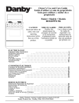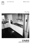
1
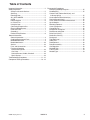
R
Service
This manual is to be used by qualified appliance
technicians only. Maytag does not assume any
responsibility for property damage or personal
injury for improper service procedures done by
an unqualified person.
Freestanding
Gas Ranges
This Base Manual covers general information
Refer to individual Technical Sheet
for information on specific models
This manual includes, but is
not limited to the following:
DGRSC and
RJGR
Models
16023219
December 2004
Important Information
Important Notices for Servicers and Consumers
Maytag will not be responsible for personal injury or property damage from improper service procedures. Pride and
workmanship go into every product to provide our customers with quality products. It is possible, however, that during
its lifetime a product may require service. Products should be serviced only by a qualified service technician who is
familiar with the safety procedures required in the repair and who is equipped with the proper tools, parts, testing
instruments and the appropriate service information. IT IS THE TECHNICIANS RESPONSIBILITY TO REVIEW ALL
APPROPRIATE SERVICE INFORMATION BEFORE BEGINNING REPAIRS.
!
WARNING
To avoid risk of severe personal injury or death, disconnect power before working/servicing on appliance to avoid
electrical shock.
To locate an authorized servicer, please call (866) 820-9401 or contact the dealer from whom you purchased this
product. For further assistance, please contact:
Customer Service Support Center
CAIR Center
Web Site
Telephone Number
WWW.MAYTAG.COM ............................................. 1-866-820-9401
CAIR Center in Canada ........................................... 1-800-688-2002
Amana Canada Product ........................................... 1-866-587-2002
Recognize Safety Symbols, Words, and Labels
! DANGER
DANGER—Immediate hazards which WILL result in severe personal injury or death.
!
WARNING
WARNING—Hazards or unsafe practices which COULD result in severe personal injury or death.
!
CAUTION
CAUTION—Hazards or unsafe practices which COULD result in minor personal injury, product or property
damage.
2
16023219
©2004 Maytag Services
Table of Contents
Important Information .................................................... 2
Safety Information
Safety Practices for Servicer .................................... 5
Servicing .................................................................. 5
Receiving Oven ........................................................ 5
ALL APPLIANCES ................................................... 5
OVEN ...................................................................... 5
Delayed Ignition ....................................................... 6
In Case of Fire .......................................................... 6
Using the Oven ........................................................ 6
Connecting Range to Gas ........................................ 7
Electrical Requirements ........................................... 7
Extension Cord ........................................................ 7
Grounding ................................................................ 7
Product Safety Devices ............................................ 8
General Information
General Information .................................................. 9
Ordering Replacement Parts .................................... 9
Model Nomenclature ................................................ 9
Model Identification ................................................. 10
Service .................................................................... 10
Parts and Accessories ............................................ 10
Functional Operation
Bake or Broil Ignitors ............................................. 10
Gas Valve .............................................................. 10
Surface Burners, Griddle, Charbroil ....................... 10
Spark System ....................................................... 10
Troubleshooting Procedures ................................. 11 - 12
Component Testing Procedures ............................ 13 - 14
©2004 Maytag Services
16023219
Disassembly Procedures
Removing and Replacing Unit.................................. 15
Knob Bezel(s) ......................................................... 15
Control Panel, Rocker Switch(es), and
Indicator Light(s) ................................................... 15
Surface Burner Micro Switch(es) ............................. 15
Surface Burner Valve(s) ........................................... 15
Oven and Surface Broiler Infinite Switch .................. 15
Spark Module .......................................................... 16
Module(s) Removal .................................................. 16
Oven Light Socket ................................................... 16
Convection Fan ....................................................... 16
Bake Burner and Ignitor ........................................... 16
Broil Burner and Ignitor ............................................ 17
Bake Gas Valve(s) .................................................. 17
Broiler Gas Valve(s) ................................................ 17
Backguard .............................................................. 17
Top Side Panel ....................................................... 17
Side Panel .............................................................. 17
Door Removal .......................................................... 18
Door Disassembly ................................................... 18
Gas Regulator ......................................................... 18
Manifold Pipe .......................................................... 18
Front Facade .......................................................... 19
Module Type ........................................................... 19
3
Safety Information
As with all appliances, there are certain rules to follow for
safe operation. Verify everyone who operates the oven is
familiar with the operations and with these precautions.
Use appliance only for its intended purpose as described.
Pay close attention to the safety sections of this manual.
Recognize the safety section by looking for the symbol
or the word safety.
Recognize this symbol as a safety precaution.
This gas appliance contains or produces a chemical or
chemicals which are known to the state of California to
cause cancer, birth defects or other reproductive harm.
To reduce the risk from substances in the fuel or from
fuel combustion make sure this appliance is installed,
operated, and maintained according to the instructions
in this manual.
Due to the nature of cooking, fires can occur as a
result of overcooking or excessive grease. Although a
fire is unlikely, if one occurs proceed as follows:
!
If the information in this manual is not followed exactly,
a fire or explosion may result causing property
damage, personal injury or death.
Do not store or use gasoline or other flammable vapors
or liquids in the vicinity of this or any other appliance.
WHAT TO DO IF YOU SMELL GAS
• Extinguish any open flame.
• Do not try to light any appliance.
• Do not touch any electrical switch; do not use any
phone in your building.
• Immediately call your gas supplier from a neighbor’s
phone. Follow the gas supplier’s instructions.
• If you cannot reach your gas supplier, call the fire
department.
Installation and service must be performed by an
authorized installer, service agency or gas supplier.
Oven Fires
1. Do not open the oven door.
2. Turn all controls to the OFF position.
3. As an added precaution turn off the electricity at
the main circuit breaker or fuse box and the gas
at the main supply valve.
4. Allow the food or grease to burn itself out in the
oven.
If smoke or fire persist call the local fire department.
To avoid risk of property damage or personal injury do
not obstruct the flow of combustion or ventilation air to
the oven.
To avoid risk of electrical shock, serious personal injury
or death: Verify the oven has been properly grounded
and always disconnect the electrical supply before
servicing this unit.
NOTE: The maximum gas supply pressure for these
models must not exceed 14 inches W.C.P.
To avoid risk of electrical shock, property damage,
personal injury or death; verify wiring is correct, if
components were replaced. Verify proper and
complete operation of unit after servicing.
4
16023219
©2004 Maytag Services
Safety Information
Safety Practices for Servicer
Safe and satisfactory operation of gas ranges depends
upon its design and proper installation. However, there is
one more area of safety to be considered:
Servicing
Listed below are some general precautions and safety
practices which should be followed in order to protect the
service technician and consumer during service and after
service has been completed.
1. Gas smell—Extinguish any and all open flames and
open windows.
2. Turn gas off—Service range with gas turned off
unless testing requires it.
3. Checking for gas leaks—Never check for leaks
with any kind of open flame. Soap and water solution
should be used for this purpose. Apply solution to
suspected area and watch for air bubbles which
indicates a leak. Correct leaks by tightening fittings,
screws, connections, applying approved compound,
or installing new parts.
4. Using lights—Use a hand flashlight when servicing
ranges or checking for gas leaks. Electric switches
should not be operated where leaks are suspected.
This will avoid creating arcing or sparks which could
ignite the gas. If electric lights are already turned on,
they should not be turned off.
5. Do not smoke—Never smoke while servicing gas
ranges, especially when working on piping that
contains or has contained gas.
6. Check range when service is completed—After
servicing, make visual checks on electrical
connection, and check for gas leaks. Inform
consumer of the condition of range before leaving.
7. Adhere to all local regulations and codes when
performing service.
Receiving Oven
• Installer needs to show consumer location of the
range gas shut-off valve and how to shut it off.
• Authorized servicer must install the range, in
accordance with the Installation Instructions.
Adjustments and service should be performed only by
authorized servicer.
• Plug range into a 120–volt grounded outlet only. Do
not remove round grounding prong from the plug. If in
doubt about grounding of the home electrical system,
it is consumers responsibility and obligation to have an
ungrounded outlet replaced with a properly grounded
three-prong outlet in accordance with the National
Electrical Code. Do not use an extension cord with
this appliance.
• Insure all packing materials are removed from the
range before operating it, to prevent fire or smoke
damage should the packing material ignite.
©2004 Maytag Services
16023219
• Ensure range is correctly adjusted by a qualified
service technician or installer for the type of gas
(Natural or LP). Some ranges can be converted for
use with Natural or LP gas.
• With prolonged use of a range, high floor temperatures
could result. Many floor coverings will not be able to
withstand this kind of use. Never install range over vinyl
tile or linoleum that cannot withstand high
temperatures. Never install range directly over
carpeting.
ALL APPLIANCES
1. Proper Installation—Be sure your appliance is
properly installed and grounded by a qualified
technician.
2. Never Use Appliance for Warming or Heating the
Room.
3. Do Not Leave Children Alone—Children should not be
alone or unattended in the area where the appliance
is in use. They should never be allowed to sit or stand
on any part of the appliance.
4. Wear Proper Apparel—Loose fitting or hanging
garments should never be worn while using appliance.
5. User Servicing—Do not repair or replace any part of
the appliance unless specifically recommended in the
manual. All other servicing should be referred to a
qualified technician.
6. Storage in or on Appliance—Flammable materials
should not be stored in oven.
7. Do Not Use Water on Grease Fires—Smother fire or
flame, or use dry chemical or foam-type extinguisher.
8. Use Only Dry Potholders—Moist or damp potholders
on hot surfaces may result in burns from steam. Do
not let potholder touch burners. Do not use a towel or
other bulky cloth.
OVEN
1. Use Care When Opening Door—Let hot air or steam
escape before removing or replacing food.
2. Do Not Heat Unopened Food Containers—Build-up of
pressure may cause container to burst and result in
injury.
3. Keep Oven Vents Ducts Unobstructed.
4. Placement of Oven Racks—Always place oven racks
in desired location while oven is cool. If rack is
removed while oven is hot, do not let potholder
contact hot heating element in oven.
5
Safety Information
Delayed Ignition
Bake Burner Flame
Allow no more than 40–60 seconds before burner ignites
and heat is felt. To check for heat, open oven door to first
stop and place hand over oven door. If heat is not felt,
cancel bake funtion. If burner repeatedly fails to ignite,
contact an authorized servicer.
Broiler Flame
Allow no more than 40–60 seconds before burner ignites
and flame is seen. If burner does not ignite cancel broil
function. If burner repeatedly fails to ignite within 40–60
seconds contact an authorized servicer.
Radiant screen style broiler flame should appear hazy or
fuzzy. Haze should be no more than 3/8–inch thick. The
radiant screen should begin to glow red within 1–2
minutes.
In Case of Fire
Fires can occur as a result of over cooking or excessive
grease. Though a fire is unlikely, if one occurs, proceed
as follows:
Oven Fires
1. If you see smoke from oven, do not open oven door.
2. Turn oven control to OFF.
3. As an added precaution, turn off gas supply and
power at main circuit breaker or fuse box.
4. Turn on vent to remove smoke.
5. Allow food or grease to burn itself out in oven.
6. If smoke and fire persist, call fire department.
7. If there is any damage to components, call repair
service before using oven.
If smoke or fire persist call the local fire department.
To avoid the risk of property damage or personal injury do
not obstruct the flow of combustion or ventilation air to
the oven.
To avoid the risk of electrical shock, serious personal
injury or death: Make sure your oven has been properly
grounded and always disconnect the electrical supply
before servicing this unit.
Using the Oven
• Do not leave children alone or unattended where a
range is hot or in operation. They could be seriously
burned.
• Do not allow anyone to climb, stand or hang on the
door. They could damage the range and cause severe
personal injury.
• Wear proper apparel. Loose fitting or hanging garments
should never be worn when using oven. Flammable
material could ignite if brought in contact with flame or
hot oven surfaces which may cause severe burns.
• Never use range for warming or heating a room. This
6
16023219
may cause burns, injuries, or a fire.
• Do not use water on grease fires.
• Do not let grease or other flammable materials collect
in or around range.
• Do not repair or replace any part of range unless it is
recommended in this manual.
• Use only dry potholders. Moist or damp potholders
used on hot surfaces may result in a burn from steam.
Do not let a potholder touch the flame. Do not use a
towel or a bulky cloth as a potholder.
• Never leave range unattended while cooking. Boilovers
can cause smoking and may ignite.
• Only certain types of glass/ceramic, earthenware, or
other glazed utensils are suitable for use in gas ovens.
Unsuitable utensils may break due to sudden
temperature change.
• Use care when opening oven door. Let hot air or steam
escape before removing or replacing food.
• Do not heat unopened food containers in oven.
Build-up of pressure may cause a container to burst
and result in injury.
• Keep range vent ducts unobstructed.
• Place oven racks in desired location while oven is cool.
If a rack must be moved while oven is hot, use a dry
potholder.
• Do not use aluminum foil to line oven bottom or racks.
Aluminum foil can cause a fire and will seriously affect
baking results, and damage to porcelain surface's.
• Do not touch interior surfaces of oven during or
immediately after use. Do not let clothing or other
flammable materials come in contact with bake or broil
burners.
• Other areas of the oven can become hot enough to
cause burns, such as vent openings, window, oven
door and oven racks.
• To avoid steam burns, do not use a wet sponge or
cloth to wipe up spills on hot cooking area.
• Do not store combustible or flammable materials, such
as gasoline or other flammable vapors and liquids near
or in oven.
• Do not clean oven door gasket located on back of the
door. Gasket is necessary to seal the oven and can be
damaged as a result of rubbing or being moved.
• Do not drape towels or any materials on oven door
handles. These items may ignite causing a fire.
!
CAUTION
Do not store items of interest to children in cabinets
above range. Children may climb on oven to reach
these items and become seriously injured.
©2004 Maytag Services
Safety Information
Connecting Range to Gas
Install manual shut-off valve in gas line for easy
accessibility outside range. Be aware of the location of
the shut-off valve.
Electrical Requirements
120-volt, 60 Hertz, 15 amp, individual circuit which is
properly grounded, polarized and protected by a circuit
breaker or fuse.
Extension Cord
Due to possible pinching during installation, extension
cords should not be used on products.
Extension cords will adversely affect the performance of
spark system.
Grounding
NOTE: This appliance must be properly grounded, for
personal safety.
Power cord on this appliance is equipped with a threeprong grounding plug. This matches standard threeprong grounding wall receptacle to prevent possibility of
electric shock from this appliance.
Consumer should have wall receptacle and circuit
checked by qualified electrician to verify receptacle is
properly grounded.
!
WARNING
Attaching adapter ground terminal to wall receptacle
cover screw does not ground appliance unless the
cover screw is metal and not insulated, and wall
receptacle is grounded through the house wiring.
Consumer should have circuit checked by a qualified
electrician to verify receptacle is properly grounded.
When disconnecting power cord from adapter, always
hold adapter with one hand. If this is not done, adapter
ground terminal is very likely to break with repeated use.
Should this happen, DO NOT USE appliance until a
proper ground has been established.
Neutral Wire
Ground
Where standard two-prong wall receptacle is
encountered, it is consumers responsibility and
obligation to have it replaced with a properly grounded
three-prong wall receptacle.
DO NOT, UNDER ANY CIRCUMSTANCES, CUT OR
REMOVE THE THIRD (GROUND) PRONG FROM
POWER CORD.
Hot Line
NOTE: Circuit tester can be use to verify voltage is
present at the outlet, connect one lead to hot
line and the other lead to ground, circuit tester
should light.
For 15 amp circuits only. Do not use an adapter on 20
amp. circuit. Where local codes permit, a TEMPORARY
CONNECTION may be made to properly grounded twoprong wall receptacle by the use of a UL listed adapter
available at most hardware stores.
Larger slot on adapter must be aligned with larger slot in
the wall receptacle to provide proper polarity.
©2004 Maytag Services
16023219
7
Safety Information
Product Safety Devices
Safety devices and features have been engineered into the product to protect consumer and servicer. Safety devices
must never be removed, bypassed, or altered in such a manner as to defeat the purpose for which they were intended.
Listed below are various safety devices together with the reason each device is incorporated in the gas ranges.
Pressure Regulator
Maintains proper and steady gas pressure for operation of oven controls. Regulator
must be set for the type of gas being used Natural or LP. After servicing regulator,
make certain it is set properly before completing service.
Gas Burner Orifices
Universal orifices are used on most valves. They must be adjusted or set for the
type of gas being used Natural or LP.
After servicing a valve or orifice verify it is adjusted properly before completing
service.
Oven Safety Valve
Oven valve is designed to be a safety valve. Two basic designs are used in gas
ranges.
Hydraulic type valve
Electric type valve
Both types are safety valves because they are indirectly operated by the oven
thermostat, which controls a pilot flame or electric ignitor, to open and close the
oven valve.
Grounded Oven Frame
Ground prong on power cord is connected to the frame, usually a green lead
fastened by a screw. In addition, any part or component capable of conducting an
electric current is grounded by its mounting.
If any ground wire, screw, strap, nut, etc. is removed for service, or any reason, it
must be reconnected to its original position with original fastener before the
appliance is put into operation again.
Failure to do so can create a possible shock hazard.
8
16023219
©2004 Maytag Services
General Information
General Information
This manual provides basic instructions and suggestions for handling, installing and servicing gas ranges.
The directions, information, and warnings in this manual are developed from experience with, and careful testing of
the product. If the unit is installed according to the Installation Instructions, it will operate properly and will require
minimal servicing. A unit in proper operating order ensures the consumer all the benefits provided by clean, modern
gas cooking.
This manual contains information needed by authorized service technicians to install and service gas ranges. There
may be, however, some parts which need further explanation. Refer to individual technical sheets or the toll-free
technical support line to answer questions from authorized service technicians.
Ordering Replacement Parts
Model numbers are recorded on the rating label. Rating label is located inside the burner box area. Before ordering
parts, write down the correct model and serial number from rating label. This avoids incorrect shipments and delays.
Please refer to parts reference material when ordering replacement parts.
DGRSC
48
4
GCB
Model Width
30"
36"
48"
60"
Model Type
DGRSC – Shallow depth
range with
convection oven
DCT –
Cooktops
DVH –
Ventilation Hoods
(Other markings
unique for hoods)
Open Burner
4 thru 9
Top Sections
G–
Griddle
CB – Char-broiler
WOK – Wok with adapter
SSB
GT
Accent Option
GT – Gold Trim
If not unit will be trimmed in Stainless
and Chrome.
Gas Type
LP – Liquid Propane
If not unit will be set for Natural Gas
LP
©2004 Maytag Services
Outside Finishes
Black
White
Hunter Green
Stainless Steel Front,
(black sides)
SSB – Stainless Steel Body
(front & Sides
B W HG SSF –
16023219
9
General Information
Model Identification
Gas Valve
Complete registration card and promptly return. If
registration card is missing:
Bake and broil dual gas valves supply gas to the bake
and broil burners. Valves contain a bimetal arms
attached to the valve seats. These arms are wrapped
with a small electric heater coil. When current range of
approximately 3.3 to 3.6 amper flows through the bake
or broil circuit, the bimetal arm is heated. Heating
causes the arm to bend, allowing gas to flow and be
ignited by the burner ignitor.
• For Jade product call 1-866-820-9401 or visit the Web
Site at www.jadeappliances.com
When contacting provide product information located on
rating plate. Record the following:
Model Number:
Manufacturing Number:
Serial or S/N Number:
Date of purchase:
Dealer’s name and address:
___________________
___________________
___________________
___________________
___________________
Service
Keep a copy of sales receipt for future reference or in
case warranty service is required. To locate an
authorized servicer:
• For Jade product call 1-866-820-9401 or visit the Web
Site at www.jadeappliances.com
Warranty service must be performed by an authorized
servicer. We also recommend contacting an authorized
servicer, if service is required after warranty expires.
One spark ignitor is used for each pair of burners. The
ignitor is located between the flash tubes covered by a
metal bracket to provide a grounding surface for ignition.
The surface burners have standard typical valves with a
micro switch, which slides onto the shaft of the valve.
When turning the surface valve to lite position, the
internal shaft of the valve rotates and turns the micro
switch on.
NOTE: If any surface valve is turned to lite position all
electrodes will spark.
Spark System
Parts and Accessories
Purchase replacement parts and accessories over the
phone. To order accessories for your product call:
• For Jade product call 1-866-820-9401 or visit the Web
Site at www.jadeappliances.com
Functional Operation
Bake or Broil Ignitors
Bake and broil ignitors are mounted to the bake and
broil burners. They ignite the gas flowing into the burner.
During bake or broil operations, current flows through
the ignitor, gas valve, and thermostat to neutral. As the
ignitor heats up and starts glowing, it’s internal
resistance decreases. This allows more current to flow
through the bake or broil circuit.
When ciruit current reaches approximately 3.3 to 3.6
ampers. The bimetal arm in the gas valve flexes,
opening the valve and allowing gas to flow to the burner,
where it is ignited by the glowing ignitor. Ignitors glow
anytime bake or broil burners are operating and cycle on
and off with the thermostat cycling contacts.
10
Surface Burners, Griddle, Charbroil
16023219
The spark ignition system consists of a solid state
module, spark ignitors, and micro switches.
By turning a surface burner knob to LITE postion. The
spark module sends approximately 2 sparks per second
to the spark ignitors. This is achieved by turnning the
burner knob, which rotates the micro switch located on
the valve stem. Which causes a demand for spark from
the spark module containing an electronic circuit which
produces high voltage pulses.
NOTE: When any surface burner is turned to the “ON”
position all surface burners on that circuit will
spark.
By turning a oven burner knob to LITE postion. The
spark module sends approximately 2 sparks per second
to the spark ignitors. This is achieved by turnning the
burner knob, which rotates the micro switch located on
the valve stem. Which causes a demand for spark from
the spark module containning an electronic circuit which
produces high voltage pulses.
©2004 Maytag Services
Troubleshooting Procedures
!
WARNING
To avoid risk of electrical shock, personal injury or death; disconnect power and shut off gas to unit before
servicing, unless testing requires power.
Problem
Burners will not ignite; no
spark at top burner.
Possible Cause
Poor ground at ignitor..................................
Weak or failed spark module.......................
Low gas pressure ........................................
No 120 VAC to range ..................................
Micro switch contacts not closing................
Burner will not ignite. No
spark to burner ignitors
when burner knob is rotated
to “LITE” position.
Faulty wiring. Bad connection at burner
electrode and electrode socket ...................
Inoperative spark module............................
Electrode dirty .............................................
Cracked or broken electrode, electrode
wire or electrode socket ..............................
No spark or only random
spark at one ignitor.
Check for cracked ignitor or pinched ignitor
wire .............................................................
Poor continuity to ignitor..............................
Bad ground connection or lack of continuity
to ground or ignitor ......................................
Cracked or broken ignitor extension lead ...
Shorted valve switch/harness .....................
Unit continues to spark after
knob is turned to OFF
position.
©2004 Maytag Services
Switch has slipped off the valve ..................
16023219
Correction
• Verify spark.
• Replace spark module.
• Verify pressure 4” WCP for
natural, 10” WCP for LP.
• Verify voltage at wall outlet.
• Check wiring against appropriate
wiring diagram, Verify all
terminals and connections are
correct and tight. Check micro
switch contacts.
• Check wiring against appropriate
wiring diagram. Verify all
terminals and connections are
correct and tight.
• Check module according to
testing procedures information.
• Clean electrode.
• Replace electrode.
• Replace ignitor lead or electrode.
• Verify spark.
• Tighten ground connection and
correct any breaks in ground path
from ignitor path to unit ground
path.
• Replace ignitor lead.
• Replace switch/harness. If
shorting is caused by excessive
spillovers, customer education is
advised.
• Carefully reposition switch on
valve and rotate from OFF to
high, several times to verify
switch is not broken.
11
Troubleshooting Procedures
!
WARNING
To avoid risk of electrical shock, personal injury or death; disconnect power and shut off gas to unit before
servicing, unless testing requires power.
Problem
Possible Cause
No voltage to control. ..................................
No oven operation in bake or
broil.
Loose wire connection or broken wire.........
•
•
Failed ignitor. ...............................................
•
Gas pressure too high .................................
•
Failed gas valve ..........................................
Loose wire connection or broken wire.........
•
•
Ignitor positioned too far from burner ..........
•
Dirt or grease in orifice or burner ................
Insufficient gas pressure .............................
•
•
No gas flows to burner.
Ignitor glows red.
Gas flows to bake/broil
burner, but burner does not
light.
Power outage ..............................................
•
•
Oven light does not operate.
Failed oven lamp .........................................
•
Failed wiring ................................................
•
Failed light socket........................................
Failed light plunger ......................................
Normal .........................................................
•
•
•
Oven smokes/odor first few
times of usage
•
No power to fan motor.................................
•
Failed fan motor or winding or frozen shaft.
•
Fan motor does not operate.
12
16023219
Correction
Check for 120 VAC at control. If
no voltage is present, Replace
control.
Verify all connections are clean
and tight, replace broken wire.
Check ignitor current draw.
Replace ignitor if it fails test.
Check for correct gas pressure.
Natural gas pressure should be
4" WCP and LP gas pressure
should be 10" WCP.
Check gas valve for continuity
Verify all connections are clean
and tight, replace broken wire.
Reposition ignitor closer to
bake/broil burner.
Clean orifice or burner.
Check for correct gas pressure.
Natural gas pressure should be
4" WCP and LP gas pressure
should be 10" WCP.
Verify power is present at unit.
Verify that the circuit breaker is
not tripped.
Replace household fuse, but do
not fuse capacity.
Check lamp and replace is
necessary.
Check for broken, loose or dirty
connections.
Check light socket for continuity.
Check plunger for continuity.
Minor smoking or order is normal
the first few times of oven usage.
Ventilate area well and perform
self-clean cycle.
Check for 120 VAC supplied at
fan motor. If no voltage is
present, check for broken or
loose wiring between fan motor
and relay board. If voltage is
present at fan motor, go to the
next step.
Check motor winding for
continuity. Check for a frozen
motor shaft. Check for broken
wiring between motor and neutral
terminal block.
©2004 Maytag Services
Component Testing Procedures
!
WARNING
To avoid risk of electrical shock, personal injury or death; disconnect power and shut off gas to unit before
servicing, unless testing requires power.
Illustration
Component
Oven light housing
Rocker switch
Convection motor fan
Controls
Test Procedure
Results
Disconnect connector and test
resistance of terminals......................
Verify bulb is plugged in properly.
Indicates continuity with bulb installed.
Measure voltage at oven light...........
12 VAC, see wiring diagram for
terminal identification.
If no voltage is present at oven light,
check wiring or light switches.
Measure continuity of switch positions:
Closed ..............................................
Open ................................................
Continuity
Infinite
Verify supply voltage..........................
120 VAC
Check continuity of terminals, and
verify terminals are not shorted to
chassis...............................................
Approximately 80 Ω
Verify proper operation.
Open at 225°F, Closes at 165°F
GND
Griddle thermostat
Verify supply voltage..........................
120 VAC
Oven thermostat
Verify supply voltage..........................
120 VAC
Pressure regulator
Verify gas pressure (WCP).
Spark module
4+0
If on LP service, verify proper gas
supply conversion.
Test for voltage at terminals
L and N...........................................
Polarity and ground ........................
Input
L or N
Holder orifice
5" Natural
10" LP/Propane
120 VAC
Not subject to polarity
Verify gas pressure (WCP).
5" Natural
10" LP/Propane
Spark ignition
electrode
©2004 Maytag Services
Check orifice for debris.
Test for resistance of spark lead ..........
Clean as needed.
Continuity
Test ignitor to chassis ..........................
No continuity from ignitor to chassis.
16023219
13
Component Testing Procedures
!
WARNING
To avoid risk of electrical shock, personal injury or death; disconnect power and shut off gas to unit before
servicing, unless testing requires power.
Illustration
Component
270° valve
Test Procedure
Verify gas is supplied.
Results
Orifice adjusted for
Natural or LP.
Spark 270° switch
Top surface burner
Adjust set screw for simmer control.
Unplug switch harness at rear of
range. Test for continuity at wire
terminals.
Switch in LITE position.......................
Switch in any other position ...............
Verify gas is supplied ..........................
See conversion section.
120 VAC
Continuity
Infinite
Check for obstructions in burner ports.
Verify burner cap is positioned
correctly.
14
16023219
©2004 Maytag Services
Disassembly Procedures
!
To avoid the risk of electrical shock, personal injury or
death; disconnect power to oven and shut off gas
supply before following any disassembly procedure.
WARNING
Removing and Replacing Unit
Surface Burner Micro Switch(es)
1. Turn off gas and power supply to the oven.
1. Turn off gas and power supply to the oven.
2. Release control panel cover, see "Control Panel"
procedure, steps 1 through 5.
3. Disconnect and label wire terminals from micro
switch located on the burner valve.
4. Remove micro switch from burner valve, by pulling
switch from burner valve.
5. Replace component and reverse procedure to
reassemble.
NOTE: To avoid property damage, place a protective
covering on the floor.
2. Slide unit forward, out of the installation position.
3. Disconnect or unplug the power cord leading from
unit to junction box or outlet depending on
connection.
4. Turn off gas supply and disconnect from main gas
line.
5. Reinstall oven, using Installation Instructions.
Knob Bezel(s)
1. Turn off gas and power supply to the oven.
2. Remove surface burner knobs from control panel, by
pulling knobs straight off.
3. Remove oven control knobs from control panel.
• Rotating knob to gain access to set screw.
• Loosen set screw on knob.
• Rotate knob to "OFF" position and remove.
4. Remove screws securing knob bezel to control
panel.
5. Replace component and reverse procedures to
reassemble.
Control Panel, Rocker Switch(es), and
Indicator Light(s)
1. Turn off gas and power supply to the oven.
2. Remove surface burner knobs from control panel, by
pulling knobs straight off.
3. Remove oven control knobs from control panel.
• Rotating knob to gain access to set screw.
• Loosen set screw on knob.
• Rotate knob to "OFF" position and remove.
4. Remove screws securing control panel cover to
chassis.
5. Roll top portion of control panel cover downward to
gain access to components.
6. Disconnect and label wire terminals from rocker
switches.
7. Slide indicator lights to the side to release from
holders.
Surface Burner Valve(s)
1. Release control panel cover, see "Control Panel"
procedure, steps 1 through 5.
2. Remove micro switch from burner valve.
3. Disconnect gas line from surface valve.
4. Unscrew burner valve from manifold pipe.
NOTE: Some additional components maybe required to
be disconnected or removed. This will allow
access for valve to be unscrewed from manifold
pipe.
5. Replace component and reverse procedure to
reassemble.
NOTE: When installing valve, use pipe dope
compound. Perform gas leak test to ensure unit
will not leak and unit operates properly.
Oven and Surface Broiler Infinite Switch
1. Turn off gas and power supply to the oven.
2. Release control panel cover, see "Control Panel"
procedure, steps 1 through 5.
3. Disconnect clips securing sensor bulb.
4. Remove screws securing switch to mounting
bracket.
5. Disconnect and label wire terminals from switch.
6. Slowly guide sensor bulb from unit.
7. Replace component and reverse procedures to
reassemble.
NOTE: Perform gas leak test to ensure unit will not leak
and unit operates properly.
NOTE: Once an indicator light is released from the
holder the front lens will fall out.
©2004 Maytag Services
16023219
15
Disassembly Procedures
!
To avoid the risk of electrical shock, personal injury or
death; disconnect power to oven and shut off gas
supply before following any disassembly procedure.
WARNING
Spark Module
Convection Fan
1. Turn off gas and power supply to the oven.
2. Release control panel cover, see "Control Panel"
procedure, steps 1 through 5.
3. Locate spark module, looking through control panel
inside the burner box area at the rear of the unit.
4. Remove surface module located on top of spark
module, to gain access to spark module.
1. Open oven door and remove oven racks from the
oven cavity.
2. Remove screws securing convection fan cover to the
rear of the oven cavity.
3. Raise upward on convection fan cover to release
from supporting bracket.
4. Remove bolts securing convection fan to mounting
bracket.
5. Pull convection fan into oven cavity area and place to
the side.
6. Reach through convection fan hole located in the
rear of the oven cavity, following the wires.
7. Locate the terminal wire plug, sqeeze the side of the
terminal plug and pull to release.
8. Remove convection fan from the oven cavity.
9. Loosen set screw securing the fan blade to the
convection fan shaft and remove fan blade.
10.Remove nuts securing convection fan to the
mounting bracket.
11. Replace component and reverse procedures to
reassemble.
NOTE: Disconnect gas line at the surface valve for
module removal.
5. Remove screws securing spark module mounting
bracket to back of unit. Allow mounting bracket to fall
into burner box area.
6. Disconnect and label wire terminals from spark
module.
7. Release plastic tabs securing spark module to
mounting bracket.
8. Replace component and reverse procedures to
reassemble.
NOTE: Perform gas leak test to ensure unit will not leak
and unit operates properly.
Module(s) Removal
1.
2.
3.
4.
Remove top assembly pieces from module.
Disconnect and label wire terminals from module.
Disconnect gas line from the surface valve.
Raise upward on the rear of the module and side
back slightly to release module from orifice and
place to the side.
5. Reverse procedure to reassemble.
Oven Light Socket
1. Turn off gas and power supply to the oven.
2. Identify location of failed oven light.
• If located on an outside oven wall, remove
appropriate side panel, to gain access to oven
light, see "Side Panel" procedure.
• If located on oven interior wall,
3. Disconnect and label wire terminals from light
socket.
4. Open oven door and remove light lens cover from
light socket.
5. Release metal tabs on light socket and allow light
socket to release into the oven cavity area.
6. Replace component and reverse prodceure to
assemble.
16
16023219
NOTE: When securing fan blade to the new convection
fan shaft allow approximately 1/4" from the
mounting bracket. Spin fan blade to ensure
blade spins freely.
Bake Burner and Ignitor
1. Shut off power and gas supply to unit.
2. Remove kick plate from under oven needing
servicing.
3. Disconnect and label wire terminals from gas valve.
4. Remove items and oven racks from oven cavity.
5. Grasp front corners of oven bottom, lift and pull
forward to remove from oven cavity.
6. Remove screw securing bake burner to oven
chassis, located at the rear of oven cavity.
7. Grasp burner and slide to the rear, while
maneuvering burner to either side to release from
burner orifice.
8. Remove screws and nuts securing ignitor to bake
burner.
9. Replace component and reverse procedure to
reassemble.
©2004 Maytag Services
Disassembly Procedures
!
To avoid the risk of electrical shock, personal injury or
death; disconnect power to oven and shut off gas
supply before following any disassembly procedure.
WARNING
Broil Burner and Ignitor
Backgaurd
1. Shut off power and gas supply to unit.
2. Release control panel cover, see "Control Panel"
procedure, steps 1 through 5.
3. Remove surface modules located over broiler.
4. Remove screws securing heat reflector.
5. Disconnect gas line from broiler.
6. Remove screws securing broiler ignitor to oven
cavity.
7. Remove screws securing broiler to oven cavity.
8. Loosen screws securing rear broiler gaurds to oven
cavity.
9. Remove screws securing front of broiler gaurds to
oven cavity.
10.Slide front portion of broiler gaurds outward to gain
access to broiler.
11. Remove broiler from oven cavity.
12.Replace component and reverse procedure to
reassemble.
NOTE: This procedure requires removal of unit from
installation position.
Bake Gas Valve(s)
NOTE: Located behind kick plate area.
1. Shut off power and gas supply to unit.
2. Remove kick plate from under oven needing
servicing.
3. Disconnect and label wire terminals from gas valve.
4. Disconnect fuel lines connected to gas valve.
5. Remove screws securing gas valve bracket to unit
chassis.
6. Replace component and reverse procedure to
reassemble.
•
Remove screws securing panel to backgaurd,
located on the back of the unit.
Top Side Panel
1. Remove top portion of module from unit, located next
to the side needing replaces.
2. Remove screws securing top side panel to the
chassis.
3. Replace component and reverse procedure to
reassemble.
Side Panel
NOTE: This procedure requires removal of unit from
installation position.
1. Remove top side panel, see "Top Side Panel"
procedure.
2. Remove screws securing top, bottom, and rear of
side panel to the chassis.
3. Pull outward on the back of the side panel and slide
panel to the rear to release side panel from the
chassis.
4. Replace component and reverse procedures to
reassemble.
NOTE: Perform gas leak test to ensure unit will not leak
and unit operates properly.
Broiler Gas Valve(s)
NOTE: Located in the surface burner box area.
1. Shut off power and gas supply to unit.
2. Release control panel cover, see "Control Panel"
procedure, steps 1 through 5.
3. Remove surface module top portion from surface
module to gain access to gas valve.
4. Disconnect and label wire terminals from gas valve.
5. Disconnect gas lines connected to gas valve.
6. Remove screws securing gas valve bracket to unit
chassis.
7. Replace component and reverse procedure to
reassemble.
NOTE: Perform gas leak test to ensure unit will not leak
and unit operates properly.
©2004 Maytag Services
16023219
17
Disassembly Procedures
!
To avoid the risk of electrical shock, personal injury or
death; disconnect power to oven and shut off gas
supply before following any disassembly procedure.
WARNING
Door Removal
Gas Regulator
1. Remove bottom kick plate.
• Pull outward on bottom portion of the kick plate to
release.
• Push upward on kick plate to release and remove
from unit.
2. Release tension spring on door hinge, by completely
removing nut from eyebolt.
3. Remove eyebolt from hinge hanger.
4. Remove hinge hanger from door hinge.
1. Turn off gas and power supply to the oven.
2. Remove surface module, located on the right side of
unit. See module type for removal procedures.
NOTE: Once hinge bolts are removed, oven door will
fall. Secure oven door before removing hinge
bolts.
NOTE: When installing, use pipe dope compound.
Perform gas leak test to ensure unit will not leak
and unit operates properly.
5. Remove bolts securing door hinge to chassis.
• Located behind oven door hinges is a metal
spacer.
6. Remove door from unit.
Door Disassembly
1. Remove oven door, see "Door Removal" procedure.
2. Place door on a protected surface to prevent
damaging the oven door.
3. Remove screws securing the bottom and sides of the
door.
NOTE: Located on the side screws is a nut used a
spacer between outer shell and inner door
assembly.
4. Carefully pry the bottom corners outward on outer
shell to allow outer shell to bypass door hinges.
5. Remove screws securing door handle and replace if
necessary.
6. Remove screws securing outer door glass and
replace if necessary.
7. Remove screws securing inner door glass brackets
and replace glass if necessary.
8. remove nuts securing inner door wrapper to inner
door.
9. Remove insulation to gain access to inner window
assembly.
10.Remove nuts securing inner window assembly and
replace if necessary.
11. Replace component and reverse procedures to
reassemble.
18
16023219
NOTE: Complete disassembly of module may not be
required to gain access to gas regulator.
3. Disconnect all gas lines from gas regulator.
4. Replace component and reverse procedure to
reassemble.
Manifold Pipe
1. Turn off gas and power supply to the oven.
2. Release control panel cover, see "Control Panel"
procedure, steps 1 through 5.
3. Remove micro switches from all surface valves.
4. Cut plastic ties securing wiring to manifold pipe.
5. Disconnect gas lines, at the union from manifold
pipe.
6. Remove bolts securing gas manifold to burner box.
7. Remove surface valves from manifold pipe.
8. Replace component and reverse procedure to
reassemble.
NOTE: When installing valve, use pipe dope
compound. Perform gas leak test to ensure unit
will not leak and unit operates properly.
©2004 Maytag Services
Disassembly Procedures
!
To avoid the risk of electrical shock, personal injury or
death; disconnect power to oven and shut off gas
supply before following any disassembly procedure.
WARNING
Front Facade
This piece is spot welded into place, so it is not
replacible.
Module Type
Surface Burner
1. Turn off gas and power supply to the oven.
2. Remove grates and burner caps from module.
3. Remove screw securing burner assembly to the
mounting bracket.
4. Remove screw securing ignitor to burner mounting
bracket.
5. Disconnect wire terminal from ignitor.
6 Replace component and reverse procedure to
reassemble.
Charboil
1. Turn off gas and power supply to the oven.
2. Remove grates from module.
3. Release control panel cover, see "Control Panel"
procedure, steps 1 through 5.
4. Disconnect gas lines from surface valve.
5. Disconnect and label wire terminals from gas valve.
6. Remove screws securing gas module to mounting
bracket.
7. Remove screws securing ignitor to module.
8. Remove nuts securing burner mounting bracket to
module.
9. Remove burner from module.
10.Replace component and reverse procedure to
reassemble.
Griddle
1. Turn off gas and power supply to the oven.
2. Remove griddle from module.
3. Remove screws securing ignitor to module.
4. Remove screw securing burner to module.
5. Remove burner from module.
6. Replace component and reverse procedure to
reassemble.
©2004 Maytag Services
16023219
19
Disassembly Procedures
!
WARNING
To avoid the risk of electrical shock, personal injury or
death; disconnect power to oven and shut off gas
supply before following any disassembly procedure.
This page is intentionally left
blank.
20
16023219
©2004 Maytag Services