1
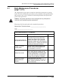
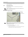
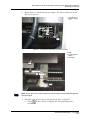
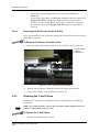
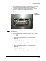
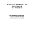
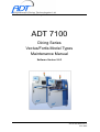
Your Resource for Advanced Dicing Solutions
ADT 7100
Dicing Series
Vectus/Fortis Model Types
Maintenance Manual
Software Version 5.6.3
P/N 97100-9005-000-14
June 2005
Customer Support
Advanced Dicing Technologies Ltd.
Advanced Technology Center
Haifa, Israel 31905
Telephone: (+972)-4-8545222
Fax: (+972)-4-8550007
Confidential
This information is the property of Advanced Dicing Technologies Ltd..
Any reproduction, publication or distribution to a third party is strictly forbidden
unless written permission is given by an authorized agent of Advanced Dicing Technologies.
ADT Model 7100 Semi-Automatic Dicing System Maintenance Manual
Periodic Maintenance
3
PERIODIC MAINTENANCE
Regular and timely maintenance is essential to keep the Model 7100 in
good operating condition. To achieve reliable performance, the
maintenance procedures listed in this chapter must be performed at the
specified intervals.
Periodic maintenance procedures include the following:
•
Examining the status of air pressure and water supplies to the System
and inside the System.
•
Inspecting the condition and performance of System assemblies and
components.
•
Performing accuracy measurements.
•
Greasing the moving assemblies and components in the System.
•
Backing up the Database at regular intervals (see Chapter 11).
Note: The schedule for backing up the Database (daily, monthly, etc.) will
depend on the user’s requirements.
This chapter contains Periodic Maintenance Tables that detail the list of
maintenance procedures to be performed, including tolerance levels, as
well as details regarding greasing procedures.
Note: The Periodic Maintenance Tables are printed single-sided for your
convenience. Photocopy and file them after completing the procedures listed.
This chapter includes the following sections:
•
Daily Maintenance Procedures (page 1 of 3), section 3.1
•
Monthly Maintenance Procedures (page 1 of 2), section 3.2
•
Quarterly Maintenance Procedures (page 1 of 3), section 3.3
•
Greasing Procedures, section 3.4
P/N 97100-9005-000-14
Ver 06/05
3-1
Periodic Maintenance
Advanced Dicing Technologies Ltd.
3-2
ADT Model 7100 Semi-Automatic Dicing System Maintenance Manual
Daily Maintenance Procedures (page 1 of 3)
3.1
Daily Maintenance Procedures
(page 1 of 3)
The maintenance procedures in this list should be performed on a daily
basis. The list includes the procedures to be performed, the specifications
that must be met, and a column for indicating whether the System has
passed each procedure.
Caution: All System operations must be stopped and any Workpieces
removed, before performing these procedures.
Photocopy this list and mark each completed procedure.
Maintenance Technician Name: ________________________
Date: ________________________
Daily Maintenance Procedures
Examine
Procedure & Specifications
Passed
Read the Air Pressure Gauge on the
Pneumatic Panel at the rear of the
System (see Figure 10-2). If the air
Level of air pressure in
pressure is below 72 psi, adjust the
the Spindle and X-Axis
Regulator located above the Gauge by
pulling the ring up, rotating the dial and
pushing the ring back into place.
Supply of Spindle
cooling water
Stop the flow of cooling water to the
Spindle. Verify that the appropriate
Error Message is received.
Water flow control
Feed cooling water onto the Cooling
Block. Verify that the reading in the
Setup & Diagnostics Workbook meets
process specifications. Verify that the
flow of water from the Cooling Block
Nozzles onto the Blade is constant.
Presence of water
leaks outside the
System
Inspect the floor in the area
surrounding the System for traces of
water. Inspect all external Tube and
hose connections.
P/N 97100-9005-000-14
Ver 06/05
3.1-1
Daily Maintenance Procedures (page 1 of 3)
Daily Maintenance Procedures
(page 2 of 3)
Maintenance Technician Name: ________________________
Date: ________________________
Daily Maintenance Procedures
Examine
Procedure & Specifications
Water leaks inside the
System
Open the Front Door and remove the
Front Bottom Cover to inspect the
Electronic Bench and the X Casting
gutter for signs of leakage. Inspect the
X Casting gutter for signs of blockage
or for a kink in the Drainage Tube.
Remove the Rear Side Lower Left
Panel and inspect the area of the
Pneumatic Panel for signs of leakage.
Cleaning Dicer
Remove all waste material that has
collected on the X Bellows.
Clean the collecting waste filter pan.
Use a sponge and clean water (DI
water recommended) to remove
sediment from:
•
X Protector
•
Cooling Block (metal parts)
•
Internal Covers
•
Wheel Mount
Cleaning Microscope
Lens
Clean the Microscope lens with a
cotton swab and isopropyl alcohol.
Height Device
For Systems with an optical,
Non-Contact Height Device:
Clean the internal vertical prism
surfaces with a cotton swab and
isopropyl alcohol and water. Clean
only the internal vertical surfaces that
face each other. Do not clean the two
external angled surfaces.
For Systems with a Mechanical Button:
Clean the surface of the Button with a
cotton swab, isopropyl alcohol and
water.
Advanced Dicing Technologies Ltd.
3.1-2
Passed
ADT Model 7100 Semi-Automatic Dicing System Maintenance Manual
Daily Maintenance Procedures (page 1 of 3)
Daily Maintenance Procedures
(page 3 of 3)
Maintenance Technician Name: ________________________
Date: ________________________
Daily Maintenance Procedures
Examine
Procedure & Specifications
Passed
Clean the LED and Sensor with a
cotton swab and isopropyl alcohol or
Broken Blade Detector
water. Tune the BBD, as described in
Chapter 7.
Hinged Covers
Clean the inside of the front
transparent covers with a clean rag and
water.
P/N 97100-9005-000-14
Ver 06/05
3.1-3
Daily Maintenance Procedures (page 1 of 3)
Advanced Dicing Technologies Ltd.
3.1-4
ADT Model 7100 Semi-Automatic Dicing System Maintenance Manual
Monthly Maintenance Procedures (page 1 of 2)
3.2
Monthly Maintenance Procedures
(page 1 of 2)
The maintenance procedures in this list should be performed on a monthly
basis after performing the daily maintenance procedures. The list includes
the procedures to be performed, the specifications that must be met, and a
column for indicating whether the System has passed each procedure.
Caution: All System operations must be stopped and any Workpieces
removed, before performing these procedures.
Photocopy this list and mark each completed procedure.
Maintenance Technician Name: ________________________
Date: ________________________
Monthly Maintenance Procedures
Examine
Procedure & Specifications
Perform Daily
Maintenance
Procedures
See section 3.1.
Clean the X Axis
Power down the System (without
turning off Air), detach the X Bellows
from the X Carriage, and clean the
surface of the X Axis with a lint-free
cloth and methanol.
Grease the X, Y & Z
Axes
See section 3.4.
Extent of Wheel Mount
Front Surface Runout
Wheel Mount Front Surface Runout
should not be greater than 2.5 microns.
(See Chapter 5 for details.)
Up and down
movements of the
MHS (for Systems
equipped with the Auto
Loader option only)
Operate the up/down movement of the
Pick-Up Arms on the MHS from the
Setup & Diagnostics Workbook.
Switch to Unprotected Mode and use
the software to manually raise and
lower the Pick-Up Arms.
Verify that each Arm moves up and
down smoothly.
Passed
Monthly Maintenance Procedures
(page 2 of 2)
Maintenance Technician Name: ________________________
P/N 97100-9005-000-14
Ver 06/05
3.2-1
Monthly Maintenance Procedures (page 1 of 2)
Date: ________________________
Monthly Maintenance Procedures
Examine
Procedure & Specifications
Condition of the
Suction Cups on the
Cutting Chuck and the
MHS (for Systems
equipped with the Auto
Loader option only)
Inspect the Suction Cups for cracks
and replace, if necessary.
Ensure that the Suction Cups are
clean. When necessary, clean the
Suction Cups with lint-free swabs and
water.
Inspecting the Spindle
Brushes
Check the amount of graphite left in
each Spindle Brush. If the length of
either Spindle Brush is 3-4mm or less,
replace both Spindle Brushes, as
described in Chapter 5.
Checking the correct
operation of the
overflow sensor
Turn on the cutting water. Then, very
carefully, move the float of the sensor
upwards. Expected results: An error
message should appear, all water in
the system should stop, the simulated
LED in the Setup & Diagnostics screen
should turn red. (see more details in
Chapter 2 of the Operation Manual).
Advanced Dicing Technologies Ltd.
3.2-2
Passed
ADT Model 7100 Semi-Automatic Dicing System Maintenance Manual
Quarterly Maintenance Procedures (page 1 of 3)
3.3
Quarterly Maintenance Procedures
(page 1 of 3)
The maintenance procedures in this list should be performed on a
quarterly basis after performing the daily and monthly maintenance
procedures. The list includes the procedures to be performed, the
specifications that must be met, and a column for indicating whether the
System has passed each procedure.
Caution: All System operations must be stopped and any Workpieces
removed, before performing these procedures.
Photocopy this list and mark each completed procedure.
Maintenance Technician Name: ________________________
Date: ________________________
Quarterly Maintenance Procedures
Examine
Procedure & Specifications
Perform Daily
Maintenance
Procedures
See section 3.1.
Perform Monthly
Maintenance
Procedures
See section 3.2.
Remove old grease
from X, Y and Z Axes
See section 3.4.
Operation of the Main
Circuit Breaker switch
and the Emergency
Stop button
Level of air pressure in
the System
•
While the System is powered on,
turn off the Main Circuit Breaker at
the right side of the System. Verify
that System operation stops
immediately.
•
While the System is operating,
push the Emergency Stop button.
Verify that System operation stops
immediately.
Passed
Read the Air Pressure Gauge on the
Pneumatic Panel (see Figure 10-2). If
the air pressure is below 4-5atm, adjust
the Regulator located on the left behind
the Rear Side Lower Left Panel by
pulling the ring up, rotating the dial and
pushing the ring back into place.
P/N 97100-9005-000-14
Ver 06/05
3.3-1
Quarterly Maintenance Procedures (page 1 of 3)
Quarterly Maintenance Procedures
(page 2 of 3)
Maintenance Technician Name: ________________________
Date: ________________________
Quarterly Maintenance Procedures
Examine
Cutting Chuck
Flatness
Procedure & Specifications
See Chapter 5.
The specifications are:
•
6 inch (150 mm) Chuck - 7 microns
•
8 inch (200 mm) Chuck 10 microns
•
12 inch (300 mm) Chuck 15 microns
Inspect the condition of the Cutting
Chuck. Clean the Chuck:
•
when dirt is apparent on the Chuck
or the underside of the Tape.
•
Condition of the
Cutting Chuck
when error messages associated
with the Cutting Chuck appear,
and other potential causes have
been ruled out.
Use ultrasonic cleaning equipment and
purified water for cleaning. Use an
Arkansas Stone to finely abrade the
surface and remove small protrusions.
Clean the underside of the Chuck by
blowing an alcohol-air mixture, then
blow with dry air until the Chuck is
completely dry.
Parallelism of the
Spindle to the X Axis
See Chapter 5.
The specification is 5 microns.
Spindle Runout (radial
& axial)
See Chapter 5.
The specification is 1 micron.
Advanced Dicing Technologies Ltd.
3.3-2
Passed
ADT Model 7100 Semi-Automatic Dicing System Maintenance Manual
Quarterly Maintenance Procedures (page 1 of 3)
Quarterly Maintenance Procedures
(page 3 of 3)
Maintenance Technician Name: ________________________
Date: ________________________
Quarterly Maintenance Procedures
Examine
Procedure & Specifications
Straightness of the
X Axis (horizontal &
vertical)
See Chapter 2.
The specification is 1 micron for a
415 mm stroke.
Accuracy of Y Axis
positioning
Place a Workpiece with a known index
on the Cutting Chuck. Perform Auto
Alignment, then measure the distance
between the first and last streets to
calculate the Index.
Cleaning the Y Axis
Linear Encoder
If a problem occurs with the Y Axis,
open the Front Cover, remove the
Y Bellows, and clean the Linear
Encoder with a cotton swab and
methanol (not isopropyl alcohol).
Z Axis Repeatability
See Chapter 6.
The specification is 1.0 micron.
Passed
Verify and Adjust
Finger Belt Tension
(for Systems equipped
with the Auto Loader
option only)
P/N 97100-9005-000-14
Ver 06/05
3.3-3
Quarterly Maintenance Procedures (page 1 of 3)
Advanced Dicing Technologies Ltd.
3.3-4
ADT Model 7100 Semi-Automatic Dicing System Maintenance Manual
Greasing Procedures
3.4
Greasing Procedures
This section describes the greasing procedures for Axes and Leadscrews on
the Model 7100. These components must be properly greased to ensure
reliable System operation, otherwise they can wear down and cause
inaccuracies.
Note: Greasing requires basic knowledge of System operation. Please refer to
the ADT Model 7100 Semi-Automatic Operations Manual for the relevant
operation procedures, as well as the safety precautions in the Safety First
section at the front of this manual, before starting the greasing procedures.
The following components should be greased every month:
•
X Axis
•
Y and Z Axis
3.4.1
Greasing Equipment
3.4.1.1
Grease Gun
Advanced Dicing Technologies recommends the Model KH-120 Grease Gun
(P/N 27795-0501-000). The Grease Gun is manufactured to meet the
JISB9808-Grease Gun-L100 standard.
Note: Any Grease Gun that meets the JISB9808 standard may be used. The
Grease Nipples on the Model 7100 meet the JISB1575 standard.
The Grease Gun may have either a press or pull-type lever for applying
grease.
3.4.1.2
Grease Type
Use ISOFLEX NBU15 grease (P/N 39087-0016-000). Contact ADT
Customer Support for purchasing information.
Note: If the Model KH-120 Grease Gun is ordered from ADT, it is delivered
greased with ISOFLEX NBU15 grease.
Caution: The Leadscrews and Linear Guides are greased before shipment of
the System to the Customer. ADT uses long-life grease that exhibits minimal
liquid-oil separation. If a different type of grease is used, there may be changes
in the greasing interval requirements, as well as chemical reactions between
the new grease and the remaining ISOFLEX NBU15 grease. It is therefore
essential to use the correct grease.
3.4.1.3
Waste Cloth
Make sure that there is a sufficient supply of waste cloth available during
greasing. Waste cloth is used for wiping off old grease or excess grease that
P/N 97100-9005-000-14
Ver 06/05
3.4-1
Greasing Procedures
is ejected during greasing. If greasing is done in clean-room conditions, use
dust-free waste cloth.
3.4.2
Greasing the X Axis
Grease the X Axis Leadscrew on a monthly basis by performing the
following procedure.
Note: On a quarterly basis, remove the old grease before applying the new
grease, as described in section 3.4.2.1.
To Grease the X Axis:
1
Open the Left Side Panel by removing the two securing screws.
1 Securing
Screws
2 Left Side Panel
1
2
Figure 3-1: Left Side Panel
Note: At this point, the user may want to disconnect the pipes that
supply water and air to the water and air gun. The water and air supply
to the System must be closed.
2
Move the X Axis to the Home position, as follows:
a.
Open the Video Workspace.
b.
Using the left group of arrows, move the X Axis left till the X Axis
grease nipple is easily accessible for the grease gun.
Advanced Dicing Technologies Ltd.
3.4-2
ADT Model 7100 Semi-Automatic Dicing System Maintenance Manual
Greasing Procedures
3
Apply grease to the X Axis grease nipple. Use waste cloth to wipe off
any excess grease.
1 Area Shown in
Detail in Figure
3-3
1
Figure 3-2: Left Side of System with Left Cover Removed
1 Bath
2 X Axis Grease
Nipple
3 X Casting
1
2
3
Figure 3-3: X Axis Grease Nipple
Note: Press the lever of the Grease Gun three times to feed sufficient grease
into the nipple.
4
Initialize and operate the newly greased X Axis, as follows:
a.
Click
in the toolbar to display the Setup & Diagnostics
workbook.
P/N 97100-9005-000-14
Ver 06/05
3.4-3
Greasing Procedures
3.4.2.1
b.
From the Setup & Diagnostics tree, select saw > Dicer >
Axes > X.
c.
In the lower right pane, click Init to initialize the axis, then click
Toggle Self Test. The X Axis begins moving automatically
between its two limits. Allow the X Axis to continue moving for
one minute, then click Toggle Self Test again to turn off the
self-test.
Removing the Old Grease from the X Axis
On a quarterly basis, the old grease should be removed from X Axis before
applying new grease.
To Remove Old Grease from the X Axis:
1
Open the Front Door of the System to reveal the X Axis Leadscrew.
1 X Axis Grease
Nipple
2 Leadscrew
1
2
Figure 3-4: Left X Leadscrew and Grease Nipple
3.4.3
2
Remove the old grease from the Leadscrew using waste paper.
3
Grease the X Axis, as described in section 3.4.2.
Greasing the Y and Z Axes
Grease the Y and Z Axes simultaneously, by performing the following
procedure.
Note: On a quarterly basis, remove the old grease before applying the new
grease, as described in section 3.4.2.
To Grease the Y and Z Axes:
1
Remove the Maintenance Panel.
Advanced Dicing Technologies Ltd.
3.4-4
ADT Model 7100 Semi-Automatic Dicing System Maintenance Manual
Greasing Procedures
2
Remove the four screws securing the Z Casting Access Panel to the
Z Casting Cover, and remove the Z Casting Access Panel.
3
In the Video Workspace use the left group of arrows to align the
Z Casting Access Panel with the Maintenance Panel.
4
Apply grease to the six grease nipples, three on each side of the
Z Casting. Use waste cloth to wipe off any excess grease.
1 Z Casting
2 Grease Nipples
1
2
Figure 3-5: Z Casting Grease Nipples
Note: Press the lever of the Grease Gun three times to feed sufficient grease
into the nipples.
5
Initialize and operate the newly greased Y and Z Axis, as follows:
a.
Click
in the toolbar to display the Setup & Diagnostics
workbook.
b.
From the Setup & Diagnostics tree, select saw > Dicer >
Axes > Y.
c.
In the lower right pane, click Init to initialize the axis, then click
Toggle Self Test. The Y Axis begins moving automatically
between its two limits. Allow the Y Axis to continue moving for
one minute, then click Toggle Self Test again to turn off the
self-test.
d.
From the Setup & Diagnostics tree, select saw > Dicer >
Axes > Z.
e.
In the lower right pane, click Init to initialize the axis, then click
Toggle Self Test. The Z Axis begins moving automatically
between its two limits. Allow the Z Axis to continue moving for
one minute, then click Toggle Self Test again to turn off the
self-test.
P/N 97100-9005-000-14
Ver 06/05
3.4-5
Greasing Procedures
3.4.3.1
Removing the Old Grease from the Y and Z Axes
On a quarterly basis, the old grease should be removed from the Y and
Z Axes before applying new grease.
To Remove the Old Grease from the Y and Z Axes:
1
In the Video Workspace, click and hold the down arrow (in the group of
arrows on the right of the Workspace) until the Z Axis reaches its
lowest position.
2
Open the Front Clear Cover.
3
Remove the eight screws (2 on front, 4 on top, 2 on back) that secure
the Z Casting Cover and remove the Cover.
1 Screws on Z
Cover (6 of 8)
2 Y Bellows Cover
3 Camera Cover
1
2
1
3
Figure 3-6: Z Casting Cover
4
Remove the four Y Bellows Cover screws and move the Bellows to one
side.
5
Remove the old grease from the Leadscrew using waste paper.
6
Grease the Y and Z Axes, as described in section 3.4.3.
7
Re-attach the Y Bellows to the Y Bellows Cover, using the screws
previously removed.
8
Re-attach the Z Casting Cover, using the eight screws previously
removed.
9
Close the hinged Spindle Cover.
Advanced Dicing Technologies Ltd.
3.4-6